US1057504A - Door-securing device. - Google Patents
Door-securing device. Download PDFInfo
- Publication number
- US1057504A US1057504A US1911619357A US1057504A US 1057504 A US1057504 A US 1057504A US 1911619357 A US1911619357 A US 1911619357A US 1057504 A US1057504 A US 1057504A
- Authority
- US
- United States
- Prior art keywords
- lever
- door
- locking element
- securing
- free end
- Prior art date
- Legal status (The legal status is an assumption and is not a legal conclusion. Google has not performed a legal analysis and makes no representation as to the accuracy of the status listed.)
- Expired - Lifetime
Links
- 210000003128 head Anatomy 0.000 description 15
- 210000001331 nose Anatomy 0.000 description 8
- 239000011435 rock Substances 0.000 description 2
- 229910001208 Crucible steel Inorganic materials 0.000 description 1
- 230000004075 alteration Effects 0.000 description 1
- 229910052729 chemical element Inorganic materials 0.000 description 1
- 230000000717 retained effect Effects 0.000 description 1
Images
Classifications
-
- E—FIXED CONSTRUCTIONS
- E05—LOCKS; KEYS; WINDOW OR DOOR FITTINGS; SAFES
- E05C—BOLTS OR FASTENING DEVICES FOR WINGS, SPECIALLY FOR DOORS OR WINDOWS
- E05C17/00—Devices for holding wings open; Devices for limiting opening of wings or for holding wings open by a movable member extending between frame and wing; Braking devices, stops or buffers, combined therewith
- E05C17/02—Devices for holding wings open; Devices for limiting opening of wings or for holding wings open by a movable member extending between frame and wing; Braking devices, stops or buffers, combined therewith by mechanical means
- E05C17/04—Devices for holding wings open; Devices for limiting opening of wings or for holding wings open by a movable member extending between frame and wing; Braking devices, stops or buffers, combined therewith by mechanical means with a movable bar or equivalent member extending between frame and wing
- E05C17/12—Devices for holding wings open; Devices for limiting opening of wings or for holding wings open by a movable member extending between frame and wing; Braking devices, stops or buffers, combined therewith by mechanical means with a movable bar or equivalent member extending between frame and wing consisting of a single rod
- E05C17/24—Devices for holding wings open; Devices for limiting opening of wings or for holding wings open by a movable member extending between frame and wing; Braking devices, stops or buffers, combined therewith by mechanical means with a movable bar or equivalent member extending between frame and wing consisting of a single rod pivoted at one end, and with the other end running along a guide member
- E05C17/28—Devices for holding wings open; Devices for limiting opening of wings or for holding wings open by a movable member extending between frame and wing; Braking devices, stops or buffers, combined therewith by mechanical means with a movable bar or equivalent member extending between frame and wing consisting of a single rod pivoted at one end, and with the other end running along a guide member with braking, clamping or securing means at the connection to the guide member
-
- Y—GENERAL TAGGING OF NEW TECHNOLOGICAL DEVELOPMENTS; GENERAL TAGGING OF CROSS-SECTIONAL TECHNOLOGIES SPANNING OVER SEVERAL SECTIONS OF THE IPC; TECHNICAL SUBJECTS COVERED BY FORMER USPC CROSS-REFERENCE ART COLLECTIONS [XRACs] AND DIGESTS
- Y10—TECHNICAL SUBJECTS COVERED BY FORMER USPC
- Y10T—TECHNICAL SUBJECTS COVERED BY FORMER US CLASSIFICATION
- Y10T292/00—Closure fasteners
- Y10T292/28—Extension link
- Y10T292/2935—Slotted or notched keeper
- Y10T292/294—Sliding catch
-
- Y—GENERAL TAGGING OF NEW TECHNOLOGICAL DEVELOPMENTS; GENERAL TAGGING OF CROSS-SECTIONAL TECHNOLOGIES SPANNING OVER SEVERAL SECTIONS OF THE IPC; TECHNICAL SUBJECTS COVERED BY FORMER USPC CROSS-REFERENCE ART COLLECTIONS [XRACs] AND DIGESTS
- Y10—TECHNICAL SUBJECTS COVERED BY FORMER USPC
- Y10T—TECHNICAL SUBJECTS COVERED BY FORMER US CLASSIFICATION
- Y10T292/00—Closure fasteners
- Y10T292/28—Extension link
- Y10T292/299—Slotted keeper
Definitions
- This invention relates to an automatic securing device for doors and the like, of the kind which can be released from the inside and the outside and which comprise on the one hand a flat angular securing lever provided with a head and on the other hand a catch plate or barrel provided with an inclined surface, a slot, and a rectangular space or chamber, said catch plate or barrel being so secured to the door frame or to the fixed door leaf, that on the closing of the door proper the head of the lever can slide up the inclined surface and fall into the space, and on the opening of the door it can slide or work in the space or chamber to the extent permitted by the same.
- the securing device of the present invention differs from known arrangements of this kind in that the securing lever is somounted on the door to be opened, that it can be turned about a vertical pivot against the action of a spring, and can also be turned about a horizontal pivot against the action of its own weight, and only be lifted out of the catch plate or barrel by raising it when the door is entirely closed and by then opening the door while the lever is raised; the lever can be raised from the inside direct, and from the outside by turning a rotatable eccentric by means of a key.
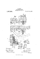
- Figure 1 shows a door provided with the door securing device, seen from inside.
- Fig. 2 is a corresponding plan, in section on A-A
- Fig. 3 is a side elevation in section on BB
- Fig. 1 is a plan of the arm that carries the securing lever, in section on CC
- Fig. 5 is a cross section through the catch plate or barrel for the lever, and which is secured to the door frame or to the fixed door leaf the section being taken on D-D
- Fig. 6 is a cross section through the said holder on line E-E, Fig. 1.
- the securing lever Z is a flat angularly formed lever of cast steel or the like, which is so secured upon a horizontal arm 0, and a supporting disk 0 that it can be turned with a pin Z1 in the arm 0 against the action of a spring 6 in the direction of the arrow I in Fig. 2.
- the spring Z2 tends to turn the lever Z) around in the opposite direction to the arrow 1, until it comes against a cylindrical pin 0 mounted in the arm 0.
- the pin 0 works in a box 0 and at its upper end has two grooves into which a spring ring mounted in a groove turned in the box 0 can snap. By this means the pin 0 is held somewhat firmly in its position.
- the cylindrical pin 0 is turned somewhat thinner for the portion lying between the two turned grooves, so that it can be moved from the one end position, in which the spring wire ring engages in the one groove, into the other end position, in which this ring. engages in the other groove.
- the pin is drawn down into the lower position it is broughtout of the path of the lever, so that the lever Z) can be turned farther around by the action of the spring 6 or by hand in the opposite direction to the arrow 1.
- the box 0 also serves as a point for fixing the one end of the spring 6 Owing to the pivoting of the lever b about the pin 5 the lever b can be turned from the relative position of the door a and lever Z) shown in full lines in Fig. 2, into the relative posit-ion of the two parts shown in dotted lines in 2. Besides turning about the vertical pin 6 the lever b can turn with the arm 0 that carries it, about the pivot d mounted between the front and rear walls of a casing e screwed to the inside of the door a.
- the horizontal arm 0 is normally rigidly connected by two pins 0 o to a lever f rotatably mounted on the pivot (Z. One of these pins 0 is attached to a chain c and can be readily taken out.
- the weight of the securing lever 6 tends to turn it on the pivot cl in the direction of the arrow 11, shown in Fig. 1. This rotation is limited by a lever 9 attached to the lever f and which is likewise mounted to turn on the pivot d.
- the lever g is forked and works against a double eccentric h disposed between the two limbs of the fork and held against a stop If by a spring h (see Fig. 1). l Vhen the lever g is against the eccentric h, as shown in Fig. 1, the securing lever Z) is in the horizontal position Fig. 1.
- the securing lever b at its outer end has a downwardly projecting nose 6 and an upwardly projecting nose o
- a catch plate or barrel into which the outer end of the securing lever snaps on the shutting of the door, and which allows the said forward end to have a certain sliding motion but prevents the lever from being lifted out of the catch plate when the lever is even only partially slid.
- the catch plate 7 has a form similar to that of the catch plates or barrels used for door chains. It has an interior space or chamber (Fig.
- the catch plate is to be fixed at the left of the door (as shown) or at the right of the door, the right hand opening above 70 or the left hand opening above 16 must be closed. Otherwise for example with the arrangement illustrated it would be possible, when the lever b has reached the dotted position shown in Fig. 2, to raise it from outside to such an extent as to allow the head of the lever to come out of the opening above 7%,
- an angle plate is screwed under the upper part of the catch plate is, this angle plate being of such length that it can only leave one of the two openings free, either that above k or that above 73
- the angle plate 70 is slid to the left before the catch plate is screwec in place.
- two further holes k and 70 are provided in the angle plate. If the angle plate is slid fully to the left, the fixing screws k and 70 can be passed through the holes 7,6 and 70 and so secure the angle plate 70 in its other end position.
- the lever Z can be raised from the inside to such an extent that in opening the door its head 6 b can come out of the opening above k so that the door can be entirely opened.
- the lever Z) can also be raised from out side by turning the eccentric h by means of the proper key.
- the key must be inserted through the keyhole m in an escutcheon m and the door into the lock it and turned.
- the lock a is provided with followers or tumblers adapted to be put out of engagement by the proper key, so that only by the proper key can the eccentric h be turned in the direction of the arrow III against the action of the spring 71 so that the fork g, lever f attached thereto and the arm 0 carrying the lever b and connected to lever f, can be turned about the pivot d. If the securing lever Z2 is to be put out of action, the pin 0 is drawn down, so that the lever b can be swung around on the pivot 6 up to the door a. Then the pin 0 is drawn out and the arm 0 with the partsv mounted on it is turned on the pin 0 into the dotted position shown in Fig.
- the rigid connection between the levers f and g is effected by a screw 0 (see Figs. 1 and 3) inserted through a plain hole in the lever f and screwed up into a threaded hole in the lever 9.
- a screw 0 see Figs. 1 and 3
- a second plain hole f in the lever f and a second threaded hole 9 in the lever g. If the screw 0 is screwed out, the lever 6 held in its horizontal position with the parts connected to it, arm 0 and lever j, and fork 9 turned to the right until the left hand limb of the fork lies against the eccentric it, the holesf and g coincide, and the levers f and 1 can be rigidly connected together in this relative position by screwing in the screw 0.
- the lever Z By turning the eccentric h in the direction of the arrow III, the lever Z) can then again be lifted.
- the screw 0 is accessible through an opening 0 in the rear wall of the casing 6, so that the reversal from left hand fitting to right hand fitting can be accomplished in a few seconds and without opening the casing e.
- the spring 5 must also be turned around, so that it acts on the lever b in the opposite direction of rotation.
- An apparatus of the character described comprising an angular lever mounted on one member, and having a head, a locking element mounted on a second memher, said angular lever adapted to be rocked to bring its free end into engagement with said locking element and in the direction of the relative movement of the two members and having a movement to carry its free end in a direction substantially perpendicular to said rocking movement, said locking element adapted to lock the lever when said members are moving away from each other, and inclined surfaces adapted to move the head of said lever into position for locking engagement, and means accessible from the side of such members opposite to said lever and locking element to move said lever into non-locking position.
- An apparatus of the character described comprising an angular lever mounted on one member, a locking element mounted on a second member, said angular lever being adapted to be rocked to bring its free end into engagement with said locking ele ment and in the direction of the relative movement of the two members and having a movement to carry its free end in a direction substantially perpendicular to said rocking movement, said lever having a projecting nose at its free end, said locking element having a slot in its front wall in the plane of movement of the lever and said slot having at the end away from the lever, a branch at substantially a right angle to the slot and to the rocking movement of the lever, and an inclined shoulder located in said branch in the path of the free end of the lever and adapted to guide said lever into locking engagement in said slot, and means accessible from the side of said members opposite to said lever and locking element to move said lever into non-locking position from the side opposite from that to which it is secured.
- An apparatus of the character described comprising an angular lever mounted on one member, a locking element mounted on a second member, said angular lever being adapted to be rocked to bring its free end into engagement with said locking element and in the direction of the relative movement of the two members and having a movement to carry its free end in a direction substantially perpendicular to said rocking movement, said lever having a head and said locking element having an inclined surface adapted to engage the head and move the lever into position for locking engagement, a cam adapted when rocked to move said lever to carry its free end in a direction perpendicular to the rocking movement of the lever and means accessible from the side of said members opposite to said lever and locking element to rock said cam.
- An apparatus of the character described comprising an angular lever mounted on one member, a locking element mounted on a second member, said angular lever being adapted to be rocked to bring its free end into engagement with said locking element and in the direction of the relative movement of the two members and having a movement to carry its free end in a direction substantially perpendicular to said rocking movement, said lever being adapted to be mounted on its member to project in either of two direct-ions, and having a head, and said locking element having a cooperating inclined surface adapted to engage the head to move the lever into locking engagement, a forked member adapted to be secured to said lever in either of two positions, a cam located between the fork prongs of said member having two operative surfaces and adapted when rocked to act on one of the fork prongs to move said lever to carry its free end in a direction perpendicular to the rocking movement of the lever, and means accessible from the side of said members opposite to said lever and locking element to rock said cam.
- An apparatus of the character described comprising an angular lever mounted on one member, a locking element mounted on a second member, said angular lever being adapted to be rocked to bring its free end into engagement with said locking element and in the direction of the relative movement of the two members and having a movement to carry its free end in a direction substantially perpendicular to said rocking movement, said lever having a proj eeting nose at its free end, said locking element having a slot in its outer wall and said slot having at both ends branches substantially perpendicular to the slot and to the rocking movement of the lever, and an inclined shoulder located in the path of the free end of the lever and adapted to move said lever into locking engagement With said In itness whereof I have hereunto set my slot, means on said element to close either of hand 1n presence of two Witnesses.
Landscapes
- Engineering & Computer Science (AREA)
- Mechanical Engineering (AREA)
- Control Of Vending Devices And Auxiliary Devices For Vending Devices (AREA)
Description
L. SGHIFF.
DOOR SECURING DEVICE.
APPLICATION FILED APR. 6, 1911.
Patented Apr. 1,1913
@mps
COLUMBIA PLANOIJRAPH c0.. WASHINGTON, D. c.
earner.
UNTE STES LUDWIG SCHIFF, 0F BERLIN, GERMANY, ASSIGNOR TO FRITZ VOGELSANG, OF CHARLOTTENBURG, GERMANY.
DOOR-SECURING DEVICE.
To all whom it may concern:
Be it known that I, Lunwlo Sor-nrr, a citizen of the German Empire, residing at Berlin, in the Kingdom of Prussia, German Empire, have invented new and useful 1mprovements in Door-Securing Devices, of which the following is a specification.
This invention relates to an automatic securing device for doors and the like, of the kind which can be released from the inside and the outside and which comprise on the one hand a flat angular securing lever provided with a head and on the other hand a catch plate or barrel provided with an inclined surface, a slot, and a rectangular space or chamber, said catch plate or barrel being so secured to the door frame or to the fixed door leaf, that on the closing of the door proper the head of the lever can slide up the inclined surface and fall into the space, and on the opening of the door it can slide or work in the space or chamber to the extent permitted by the same.
The securing device of the present invention differs from known arrangements of this kind in that the securing lever is somounted on the door to be opened, that it can be turned about a vertical pivot against the action of a spring, and can also be turned about a horizontal pivot against the action of its own weight, and only be lifted out of the catch plate or barrel by raising it when the door is entirely closed and by then opening the door while the lever is raised; the lever can be raised from the inside direct, and from the outside by turning a rotatable eccentric by means of a key.
The invention is illustrated in one constructional form in the drawings.
Figure 1 shows a door provided with the door securing device, seen from inside. Fig. 2 is a corresponding plan, in section on A-A, Fig. 3. Fig. 3 is a side elevation in section on BB, Fig. 1. Fig. 1 is a plan of the arm that carries the securing lever, in section on CC, Fig. 3. Fig. 5 is a cross section through the catch plate or barrel for the lever, and which is secured to the door frame or to the fixed door leaf the section being taken on D-D, Fig. 1. Fig. 6 is a cross section through the said holder on line E-E, Fig. 1.
Specification of Letters Patent.
Patented Apr. 1, 1913.
Application filed. April 6, 1911. Serial No. 619,357.
In the example shown, after the securing lever has been automatically engaged on the closing of the door, the door a can only open to the position shown in dotted lines in Fig. 2. The securing lever Z), is a flat angularly formed lever of cast steel or the like, which is so secured upon a horizontal arm 0, and a supporting disk 0 that it can be turned with a pin Z1 in the arm 0 against the action of a spring 6 in the direction of the arrow I in Fig. 2. The spring Z2 tends to turn the lever Z) around in the opposite direction to the arrow 1, until it comes against a cylindrical pin 0 mounted in the arm 0. The pin 0 works in a box 0 and at its upper end has two grooves into which a spring ring mounted in a groove turned in the box 0 can snap. By this means the pin 0 is held somewhat firmly in its position. The cylindrical pin 0 is turned somewhat thinner for the portion lying between the two turned grooves, so that it can be moved from the one end position, in which the spring wire ring engages in the one groove, into the other end position, in which this ring. engages in the other groove. When the pin is drawn down into the lower position it is broughtout of the path of the lever, so that the lever Z) can be turned farther around by the action of the spring 6 or by hand in the opposite direction to the arrow 1. The box 0 also serves as a point for fixing the one end of the spring 6 Owing to the pivoting of the lever b about the pin 5 the lever b can be turned from the relative position of the door a and lever Z) shown in full lines in Fig. 2, into the relative posit-ion of the two parts shown in dotted lines in 2. Besides turning about the vertical pin 6 the lever b can turn with the arm 0 that carries it, about the pivot d mounted between the front and rear walls of a casing e screwed to the inside of the door a. The horizontal arm 0 is normally rigidly connected by two pins 0 o to a lever f rotatably mounted on the pivot (Z. One of these pins 0 is attached to a chain c and can be readily taken out.
The weight of the securing lever 6 tends to turn it on the pivot cl in the direction of the arrow 11, shown in Fig. 1. This rotation is limited by a lever 9 attached to the lever f and which is likewise mounted to turn on the pivot d. The lever g is forked and works against a double eccentric h disposed between the two limbs of the fork and held against a stop If by a spring h (see Fig. 1). l Vhen the lever g is against the eccentric h, as shown in Fig. 1, the securing lever Z) is in the horizontal position Fig. 1. The securing lever b at its outer end has a downwardly projecting nose 6 and an upwardly projecting nose o To the door frame or to the stationary door leaf is screwed a catch plate or barrel into which the outer end of the securing lever snaps on the shutting of the door, and which allows the said forward end to have a certain sliding motion but prevents the lever from being lifted out of the catch plate when the lever is even only partially slid.
In the example illustrated the catch plate 7: has a form similar to that of the catch plates or barrels used for door chains. It has an interior space or chamber (Fig.
6) of parallelopiped form, which allows of the longitudinal sliding of the head formed by the projections b and b of the lever, and a longitudinal slot 7% at the front, in which the flat lever Z) can itself slide. At the point where the head of the lever b is to enter, (in the present case at the left) an inclined surface k is provided (see Figs. 1, 2, 5). Above this inclined surface an opening is left for the entrance of the head of the lever Z2. On the closing of the door a the nose 6 at the outer end of the lever Z) slides up the inclined surface 70 and consequently the lever b is raised against the action of its weight, 2'. 6. turns on the pivot (Z. When the door is entirely closed, the nose 6 slips over the highest point of the inclined plane 7"? and drops behind the vertical wall of the catch plate 7: (see Figs. 1 and 5). If the door a is now opened, the two noses b and b are retained by the vertical walls of the catch plate so that the noses cannot come out of the catch plate. In the opening of the door the head of the lever 6 slides and turns the lever into the dotted position shown in Fig. 2. To enable the catch plate or barrel to be used for doors that open in the opposite direction and with which it has therefore to be fixed at the right and not the left, of the door to be opened, I provide at the right of the catch plate an inclined surface 70* (corresponding to the inclined surface 70 and above the said surface 76 an opening for the entrance of the head Z9 6* of the securing lever. According as the catch plate is to be fixed at the left of the door (as shown) or at the right of the door, the right hand opening above 70 or the left hand opening above 16 must be closed. Otherwise for example with the arrangement illustrated it would be possible, when the lever b has reached the dotted position shown in Fig. 2, to raise it from outside to such an extent as to allow the head of the lever to come out of the opening above 7%,
and the door could then be fully opened. In
order to prevent this, an angle plate is is screwed under the upper part of the catch plate is, this angle plate being of such length that it can only leave one of the two openings free, either that above k or that above 73 If the catch plate is is not to be screwed at the left of the door, as shoWn, but at the right, the angle plate 70 is slid to the left before the catch plate is screwec in place. For this purpose in addition to the two holes through which the two fixing screws 70 and 7c are passed in the position shown, two further holes k and 70 are provided in the angle plate. If the angle plate is slid fully to the left, the fixing screws k and 70 can be passed through the holes 7,6 and 70 and so secure the angle plate 70 in its other end position. Assuming the door to be quite closed, and the securing lever Z; therefore in the position shown in Figs. 1 and 2, the lever can be raised from the inside to such an extent that in opening the door its head 6 b can come out of the opening above k so that the door can be entirely opened. But the lever Z) can also be raised from out side by turning the eccentric h by means of the proper key. For this purpose the key must be inserted through the keyhole m in an escutcheon m and the door into the lock it and turned. The lock a is provided with followers or tumblers adapted to be put out of engagement by the proper key, so that only by the proper key can the eccentric h be turned in the direction of the arrow III against the action of the spring 71 so that the fork g, lever f attached thereto and the arm 0 carrying the lever b and connected to lever f, can be turned about the pivot d. If the securing lever Z2 is to be put out of action, the pin 0 is drawn down, so that the lever b can be swung around on the pivot 6 up to the door a. Then the pin 0 is drawn out and the arm 0 with the partsv mounted on it is turned on the pin 0 into the dotted position shown in Fig. 3, in which the lever b hangs down parallel to the door. To use the lever for doors opening in the opposite direction it is unscrewed from the pivot 5 turned into the position shown in dash-dotted lines in Fig. 2 and again fixed in place, without alteration of the position of the lever f, arm 0 and securing lever b, the left arm of the fork 9 must now come against the double eccentric 71..
The rigid connection between the levers f and g is effected by a screw 0 (see Figs. 1 and 3) inserted through a plain hole in the lever f and screwed up into a threaded hole in the lever 9. There are also provided (see Fig. 1) a second plain hole f in the lever f and a second threaded hole 9 in the lever g. If the screw 0 is screwed out, the lever 6 held in its horizontal position with the parts connected to it, arm 0 and lever j, and fork 9 turned to the right until the left hand limb of the fork lies against the eccentric it, the holesf and g coincide, and the levers f and 1 can be rigidly connected together in this relative position by screwing in the screw 0. By turning the eccentric h in the direction of the arrow III, the lever Z) can then again be lifted. The screw 0 is accessible through an opening 0 in the rear wall of the casing 6, so that the reversal from left hand fitting to right hand fitting can be accomplished in a few seconds and without opening the casing e. The spring 5 must also be turned around, so that it acts on the lever b in the opposite direction of rotation.
I claim:
1. An apparatus of the character described comprising an angular lever mounted on one member, and having a head, a locking element mounted on a second memher, said angular lever adapted to be rocked to bring its free end into engagement with said locking element and in the direction of the relative movement of the two members and having a movement to carry its free end in a direction substantially perpendicular to said rocking movement, said locking element adapted to lock the lever when said members are moving away from each other, and inclined surfaces adapted to move the head of said lever into position for locking engagement, and means accessible from the side of such members opposite to said lever and locking element to move said lever into non-locking position.
2. An apparatus of the character described comprising an angular lever mounted on one member, a locking element mounted on a second member, said angular lever being adapted to be rocked to bring its free end into engagement with said locking ele ment and in the direction of the relative movement of the two members and having a movement to carry its free end in a direction substantially perpendicular to said rocking movement, said lever having a projecting nose at its free end, said locking element having a slot in its front wall in the plane of movement of the lever and said slot having at the end away from the lever, a branch at substantially a right angle to the slot and to the rocking movement of the lever, and an inclined shoulder located in said branch in the path of the free end of the lever and adapted to guide said lever into locking engagement in said slot, and means accessible from the side of said members opposite to said lever and locking element to move said lever into non-locking position from the side opposite from that to which it is secured.
3. An apparatus of the character described comprising an angular lever mounted on one member, a locking element mounted on a second member, said angular lever being adapted to be rocked to bring its free end into engagement with said locking element and in the direction of the relative movement of the two members and having a movement to carry its free end in a direction substantially perpendicular to said rocking movement, said lever having a head and said locking element having an inclined surface adapted to engage the head and move the lever into position for locking engagement, a cam adapted when rocked to move said lever to carry its free end in a direction perpendicular to the rocking movement of the lever and means accessible from the side of said members opposite to said lever and locking element to rock said cam.
4. An apparatus of the character described comprising an angular lever mounted on one member, a locking element mounted on a second member, said angular lever being adapted to be rocked to bring its free end into engagement with said locking element and in the direction of the relative movement of the two members and having a movement to carry its free end in a direction substantially perpendicular to said rocking movement, said lever being adapted to be mounted on its member to project in either of two direct-ions, and having a head, and said locking element having a cooperating inclined surface adapted to engage the head to move the lever into locking engagement, a forked member adapted to be secured to said lever in either of two positions, a cam located between the fork prongs of said member having two operative surfaces and adapted when rocked to act on one of the fork prongs to move said lever to carry its free end in a direction perpendicular to the rocking movement of the lever, and means accessible from the side of said members opposite to said lever and locking element to rock said cam.
5. An apparatus of the character described comprising an angular lever mounted on one member, a locking element mounted on a second member, said angular lever being adapted to be rocked to bring its free end into engagement with said locking element and in the direction of the relative movement of the two members and having a movement to carry its free end in a direction substantially perpendicular to said rocking movement, said lever having a proj eeting nose at its free end, said locking element having a slot in its outer wall and said slot having at both ends branches substantially perpendicular to the slot and to the rocking movement of the lever, and an inclined shoulder located in the path of the free end of the lever and adapted to move said lever into locking engagement With said In itness whereof I have hereunto set my slot, means on said element to close either of hand 1n presence of two Witnesses.
said erpendicular branches of the slot, and mean accessible from the side of said mem- LUDWIG SGHIFF' bers opposite to said lever and locking ele- Witnesses:
ment to move said lever into non-locking HENRY HASPER,
position. WOLDEMAR HAUPT.
Copies of this patent may be obtained for five cents each, by addressing the Commissioner of Patents, Washington, D. G.
Priority Applications (1)
| Application Number | Priority Date | Filing Date | Title |
|---|---|---|---|
| US1911619357 US1057504A (en) | 1911-04-06 | 1911-04-06 | Door-securing device. |
Applications Claiming Priority (1)
| Application Number | Priority Date | Filing Date | Title |
|---|---|---|---|
| US1911619357 US1057504A (en) | 1911-04-06 | 1911-04-06 | Door-securing device. |
Publications (1)
| Publication Number | Publication Date |
|---|---|
| US1057504A true US1057504A (en) | 1913-04-01 |
Family
ID=3125757
Family Applications (1)
| Application Number | Title | Priority Date | Filing Date |
|---|---|---|---|
| US1911619357 Expired - Lifetime US1057504A (en) | 1911-04-06 | 1911-04-06 | Door-securing device. |
Country Status (1)
| Country | Link |
|---|---|
| US (1) | US1057504A (en) |
-
1911
- 1911-04-06 US US1911619357 patent/US1057504A/en not_active Expired - Lifetime
Similar Documents
| Publication | Publication Date | Title |
|---|---|---|
| KR101756565B1 (en) | Improved rotary blocking device | |
| US8256806B2 (en) | Dual cam magnetic latch system | |
| US20160244995A1 (en) | Universal lock with sliding blocking mechanism | |
| US832420A (en) | Door-check. | |
| US1057504A (en) | Door-securing device. | |
| US1377061A (en) | Electric door-lock | |
| US1238152A (en) | Barn-door lock. | |
| US1324381A (en) | Door-bolt | |
| US1158845A (en) | Lock. | |
| US2334426A (en) | Latch | |
| US970661A (en) | Latch. | |
| US962792A (en) | Lock. | |
| US2963897A (en) | Door lock | |
| EP3262257A1 (en) | Universal lock with sliding blocking mechanism | |
| GB789224A (en) | Cabinets having combined door latching and hinging means | |
| US2205973A (en) | Latch mechanism | |
| RU5201U1 (en) | THE PADLOCK | |
| US1188346A (en) | Lock and latch mechanism. | |
| US1068235A (en) | Lock. | |
| US316760A (en) | diehlmao | |
| US1221703A (en) | Door-lock. | |
| US801907A (en) | Hasp-lock. | |
| SU972022A1 (en) | Lock | |
| US938545A (en) | Safe-door cam. | |
| US978554A (en) | Lock. |