US10568630B2 - Modular magnetic devices for use in creating tissue anastomosis - Google Patents
Modular magnetic devices for use in creating tissue anastomosis Download PDFInfo
- Publication number
- US10568630B2 US10568630B2 US14/237,521 US201214237521A US10568630B2 US 10568630 B2 US10568630 B2 US 10568630B2 US 201214237521 A US201214237521 A US 201214237521A US 10568630 B2 US10568630 B2 US 10568630B2
- Authority
- US
- United States
- Prior art keywords
- modular
- magnets
- anastomosis
- magnet assembly
- magnet
- Prior art date
- Legal status (The legal status is an assumption and is not a legal conclusion. Google has not performed a legal analysis and makes no representation as to the accuracy of the status listed.)
- Active
Links
- 230000003872 anastomosis Effects 0.000 title claims abstract description 36
- 230000005291 magnetic effect Effects 0.000 title abstract description 41
- 210000000056 organ Anatomy 0.000 claims abstract description 7
- 239000000463 material Substances 0.000 claims description 10
- 238000001839 endoscopy Methods 0.000 claims description 4
- 238000000034 method Methods 0.000 abstract description 10
- 210000001835 viscera Anatomy 0.000 abstract description 5
- 238000001356 surgical procedure Methods 0.000 abstract description 4
- 230000001079 digestive effect Effects 0.000 abstract description 2
- 239000012858 resilient material Substances 0.000 description 14
- 238000000429 assembly Methods 0.000 description 8
- 230000000712 assembly Effects 0.000 description 8
- 239000000560 biocompatible material Substances 0.000 description 6
- 230000006835 compression Effects 0.000 description 5
- 238000007906 compression Methods 0.000 description 5
- 230000008901 benefit Effects 0.000 description 4
- XUIMIQQOPSSXEZ-UHFFFAOYSA-N Silicon Chemical compound [Si] XUIMIQQOPSSXEZ-UHFFFAOYSA-N 0.000 description 3
- 230000002496 gastric effect Effects 0.000 description 3
- 239000012781 shape memory material Substances 0.000 description 3
- 229910052710 silicon Inorganic materials 0.000 description 3
- 239000010703 silicon Substances 0.000 description 3
- 230000007704 transition Effects 0.000 description 3
- 238000002357 laparoscopic surgery Methods 0.000 description 2
- 230000017074 necrotic cell death Effects 0.000 description 2
- 230000008520 organization Effects 0.000 description 2
- -1 polyethylene Polymers 0.000 description 2
- 229920001343 polytetrafluoroethylene Polymers 0.000 description 2
- 239000004810 polytetrafluoroethylene Substances 0.000 description 2
- 238000001338 self-assembly Methods 0.000 description 2
- 208000004998 Abdominal Pain Diseases 0.000 description 1
- 208000002881 Colic Diseases 0.000 description 1
- 208000031481 Pathologic Constriction Diseases 0.000 description 1
- 239000004698 Polyethylene Substances 0.000 description 1
- 229920006362 Teflon® Polymers 0.000 description 1
- HZEWFHLRYVTOIW-UHFFFAOYSA-N [Ti].[Ni] Chemical compound [Ti].[Ni] HZEWFHLRYVTOIW-UHFFFAOYSA-N 0.000 description 1
- 230000006978 adaptation Effects 0.000 description 1
- 229910045601 alloy Inorganic materials 0.000 description 1
- 239000000956 alloy Substances 0.000 description 1
- 238000013459 approach Methods 0.000 description 1
- 229920000249 biocompatible polymer Polymers 0.000 description 1
- 239000003364 biologic glue Substances 0.000 description 1
- 210000001072 colon Anatomy 0.000 description 1
- 239000002131 composite material Substances 0.000 description 1
- 230000001010 compromised effect Effects 0.000 description 1
- 230000023753 dehiscence Effects 0.000 description 1
- 238000011161 development Methods 0.000 description 1
- 210000003238 esophagus Anatomy 0.000 description 1
- 239000003302 ferromagnetic material Substances 0.000 description 1
- 210000001035 gastrointestinal tract Anatomy 0.000 description 1
- 230000036541 health Effects 0.000 description 1
- 238000010348 incorporation Methods 0.000 description 1
- 208000028867 ischemia Diseases 0.000 description 1
- 230000000302 ischemic effect Effects 0.000 description 1
- 229910052751 metal Inorganic materials 0.000 description 1
- 239000002184 metal Substances 0.000 description 1
- 238000002324 minimally invasive surgery Methods 0.000 description 1
- 210000000214 mouth Anatomy 0.000 description 1
- 229910001000 nickel titanium Inorganic materials 0.000 description 1
- 229920000573 polyethylene Polymers 0.000 description 1
- 229920000642 polymer Polymers 0.000 description 1
- 239000004800 polyvinyl chloride Substances 0.000 description 1
- 230000008569 process Effects 0.000 description 1
- 230000000750 progressive effect Effects 0.000 description 1
- 230000002035 prolonged effect Effects 0.000 description 1
- 210000000664 rectum Anatomy 0.000 description 1
- 238000011160 research Methods 0.000 description 1
- 238000002271 resection Methods 0.000 description 1
- 210000002151 serous membrane Anatomy 0.000 description 1
- RYMZZMVNJRMUDD-HGQWONQESA-N simvastatin Chemical compound C([C@H]1[C@@H](C)C=CC2=C[C@H](C)C[C@@H]([C@H]12)OC(=O)C(C)(C)CC)C[C@@H]1C[C@@H](O)CC(=O)O1 RYMZZMVNJRMUDD-HGQWONQESA-N 0.000 description 1
- 239000010935 stainless steel Substances 0.000 description 1
- 229910001220 stainless steel Inorganic materials 0.000 description 1
- 208000037804 stenosis Diseases 0.000 description 1
- 230000036262 stenosis Effects 0.000 description 1
- 210000002784 stomach Anatomy 0.000 description 1
- 210000001519 tissue Anatomy 0.000 description 1
Images


Classifications
-
- A—HUMAN NECESSITIES
- A61—MEDICAL OR VETERINARY SCIENCE; HYGIENE
- A61B—DIAGNOSIS; SURGERY; IDENTIFICATION
- A61B17/00—Surgical instruments, devices or methods
- A61B17/11—Surgical instruments, devices or methods for performing anastomosis; Buttons for anastomosis
- A61B17/1114—Surgical instruments, devices or methods for performing anastomosis; Buttons for anastomosis of the digestive tract, e.g. bowels or oesophagus
-
- A—HUMAN NECESSITIES
- A61—MEDICAL OR VETERINARY SCIENCE; HYGIENE
- A61B—DIAGNOSIS; SURGERY; IDENTIFICATION
- A61B17/00—Surgical instruments, devices or methods
- A61B17/11—Surgical instruments, devices or methods for performing anastomosis; Buttons for anastomosis
-
- A—HUMAN NECESSITIES
- A61—MEDICAL OR VETERINARY SCIENCE; HYGIENE
- A61B—DIAGNOSIS; SURGERY; IDENTIFICATION
- A61B17/00—Surgical instruments, devices or methods
- A61B17/00234—Surgical instruments, devices or methods for minimally invasive surgery
- A61B2017/00292—Surgical instruments, devices or methods for minimally invasive surgery mounted on or guided by flexible, e.g. catheter-like, means
-
- A—HUMAN NECESSITIES
- A61—MEDICAL OR VETERINARY SCIENCE; HYGIENE
- A61B—DIAGNOSIS; SURGERY; IDENTIFICATION
- A61B17/00—Surgical instruments, devices or methods
- A61B2017/00743—Type of operation; Specification of treatment sites
- A61B2017/00818—Treatment of the gastro-intestinal system
- A61B2017/00827—Treatment of gastro-esophageal reflux
-
- A—HUMAN NECESSITIES
- A61—MEDICAL OR VETERINARY SCIENCE; HYGIENE
- A61B—DIAGNOSIS; SURGERY; IDENTIFICATION
- A61B17/00—Surgical instruments, devices or methods
- A61B2017/00831—Material properties
- A61B2017/00862—Material properties elastic or resilient
-
- A—HUMAN NECESSITIES
- A61—MEDICAL OR VETERINARY SCIENCE; HYGIENE
- A61B—DIAGNOSIS; SURGERY; IDENTIFICATION
- A61B17/00—Surgical instruments, devices or methods
- A61B2017/00831—Material properties
- A61B2017/00867—Material properties shape memory effect
-
- A—HUMAN NECESSITIES
- A61—MEDICAL OR VETERINARY SCIENCE; HYGIENE
- A61B—DIAGNOSIS; SURGERY; IDENTIFICATION
- A61B17/00—Surgical instruments, devices or methods
- A61B2017/00831—Material properties
- A61B2017/00876—Material properties magnetic
-
- A—HUMAN NECESSITIES
- A61—MEDICAL OR VETERINARY SCIENCE; HYGIENE
- A61B—DIAGNOSIS; SURGERY; IDENTIFICATION
- A61B17/00—Surgical instruments, devices or methods
- A61B17/11—Surgical instruments, devices or methods for performing anastomosis; Buttons for anastomosis
- A61B17/1114—Surgical instruments, devices or methods for performing anastomosis; Buttons for anastomosis of the digestive tract, e.g. bowels or oesophagus
- A61B2017/1117—Surgical instruments, devices or methods for performing anastomosis; Buttons for anastomosis of the digestive tract, e.g. bowels or oesophagus adapted for discharge after necrotisation, e.g. by evacuation, expulsion or excretion
-
- A—HUMAN NECESSITIES
- A61—MEDICAL OR VETERINARY SCIENCE; HYGIENE
- A61B—DIAGNOSIS; SURGERY; IDENTIFICATION
- A61B17/00—Surgical instruments, devices or methods
- A61B17/11—Surgical instruments, devices or methods for performing anastomosis; Buttons for anastomosis
- A61B2017/1132—End-to-end connections
-
- A—HUMAN NECESSITIES
- A61—MEDICAL OR VETERINARY SCIENCE; HYGIENE
- A61B—DIAGNOSIS; SURGERY; IDENTIFICATION
- A61B17/00—Surgical instruments, devices or methods
- A61B17/11—Surgical instruments, devices or methods for performing anastomosis; Buttons for anastomosis
- A61B2017/1135—End-to-side connections, e.g. T- or Y-connections
-
- A—HUMAN NECESSITIES
- A61—MEDICAL OR VETERINARY SCIENCE; HYGIENE
- A61B—DIAGNOSIS; SURGERY; IDENTIFICATION
- A61B17/00—Surgical instruments, devices or methods
- A61B17/11—Surgical instruments, devices or methods for performing anastomosis; Buttons for anastomosis
- A61B2017/1139—Side-to-side connections, e.g. shunt or X-connections
Definitions
- the present invention relates to a modular magnetic anastomosis device for a gastro-intestinal procedure or circumstance where anastomosis between two hollow organs is required in a minimally invasive surgery procedure.
- the present invention extends this concept by means of implementing a modular magnetic anastomosis device that can be implemented in digestive surgery or in any circumstance of anastomosis between adjacent organs or two hollow viscera.
- the modular magnetic assembly possesses the non-deployed configuration and can be placed in a small sized channel and can be used in laparoscopy and endoscopy known to the person skilled in the art.
- the modular magnetic assembly takes the deployed form at its implementation position.
- the modular assembly anastomosis device is flexible and the modular aspect of the device allows it to be available in different sizes by addition of magnetic elements and adapts to the anatomical shape of the structure in which it is to be implemented.
- the anastomosis device is linear.
- anastomosis device in another embodiment can be U-shaped in its deployed configuration.
- anastomosis device can be S-shaped in its deployed configuration.
- the device has a circular deployed configuration.
- the modular magnetic anastomosis device is a set of magnetic components, the two sets form the device used for forming an anastomosis between two bodily walls.
- the modular magnetic set is enveloped in a jacket of resilient material.
- the modular magnetic component is enveloped in a jacket of biodegradable material.
- the magnets are embedded in a biodegradable material.
- self assembly in a connected chain of magnetic components in this modular device is based on an even number of magnetic dipoles with alternate North-South/South-North orientation.
- alternate geometrical flexible materials are connected to the magnet and allow for mechanical articulation of the magnets.
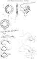
- FIG. 1 depicts how each set is formed of a chain of magnets ( 3 ), a neck comprised of flexible material ( 2 ), the resilient material ( 2 ) allows to the chain of the magnets to adopt a round structure after deployment and a jacket made of resilient material with a low friction coefficient allowing the easy movement of the device during an operation.
- FIG. 2 is a cross sectional view of the magnet chain of example 1.
- FIG. 3 illustrates the deployed form of the magnet with wire guides.
- FIG. 4 shows a variant of the magnet set.
- FIG. 5 to FIG. 9 illustrate the transition from the non-deployed linear form to the deployed circular structure of the device.
- FIG. 10 is the transition of the non deployed form of the magnet with the wire guide.
- FIG. 11 is the magnet in deployed form with the wire guides.
- FIG. 12 is a representation of the encapsulated shell attached to a flexible band of example 2.
- FIG. 13 illustrates detailed cross-representation of the assembled shell of the device of example 2.
- FIG. 14 depicts a cross-sectional view of the magnet assembly for the device of example 2.
- FIG. 15 illustrates the deployed structure of the magnet assembly.
- FIG. 16 illustrates the structure of a set of the modular magnet assembly for a device of example 3.
- FIG. 17 is a presentation of simple magnets and external jacket.
- FIG. 18 is a profile view of the set of the magnets of example 3.
- FIG. 19 illustrates the non-deployed form of the magnet assembly of example 4.
- FIG. 20 describes the deployed form of example 4.
- FIG. 21 illustrates the ring shaped modular magnetic anastomosis device in the deployed configuration of example 5.
- FIG. 22 shows a profile view of the device.
- FIG. 23 is a cross-sectional view of the magnet assemblies.
- FIG. 24 illustrates the linear non deployed configuration
- FIG. 25 describes different components of the magnet.
- FIG. 26 presents different geometrical structure of magnet and resilient material jacket.
- the circular stapler allows to perform complex procedures such as colic resections or gastric bypasses via a minimally invasive approach (laparoscopic).
- the rigid structure of circular stapler does not allow anastomosis beyond the rectum.
- using the circular stapler during a gastric bypass needs an enlarged incision through one of the operating trocars.
- Anastomosis through compression is a concept initially described by Denan in 1826 and was later popularized by Murphy in 1892 with the “Murphy Button”. It is a surgical procedure that needs introduction of two metallic rings, screwed one against the other in order to generate a constant compression force on intercalated tissues. This procedure induces secondary health issues after the anastomosis trough the ischemia ⁇ necrosis ⁇ cicatrizing cycle.
- ValtracTM a set of biofragmentable rings (Covidien, Norwalk Conn.) which are composed of two rings made of absorbable material, this device eliminate manual or mechanic suture while maintaining a comparable dehiscence and stenosis rate.
- a device called MAGNAMOSISTM, is composed of 2 magnetic rings, auto-oriented, producing a compression force with a progressive internal-external gradient. This device has been developed by the research group of Prof. Harrison from the University of San Francisco (California).
- the present invention comprises a modular magnetic device that is minimally invasive, easily and quickly delivered and is accurately positioned via laparoscopy or endoscopy, without the use of the staples.
- a magnetic anastomosis device used for forming an anastomosis between two bodily walls includes a first magnet assembly and a second magnet assembly configured to be magnetically coupled to compress the two bodily walls therebetween to form the anastomosis.
- the magnet assembly of the present invention is a modular magnetic structure with variable geometry.
- the articulated flexible modular device is composed of a network of magnetic elements placed and maintained in place by a flexible material made of resilient, biocompatible material and shape memory material or a material coated with a biocompatible material, known to a person skilled in the art.
- Suitable resilient materials include metal (e.g. stainless steel), alloys (e.g. nickel titanium) or polymers (e.g. polyethylene, polytetrafluoroethylene (PTFE) including Teflon®, polyvinyl chloride (PVC), and composites.
- the elongate modular magnet assemblies of the present invention are capable of being delivered with the same small delivery configuration as prior art, but also provide the advantage of reducing the probability of the anastomosis being closed over time and eliminating the need to intervene the patient for a second procedure to place a stent in the anastomosis to prevent closure thereof.
- those skilled in the art will recognize the centering and alignment advantages of having two magnets disposed within each of the respective magnet assemblies.
- the modular magnetic assembly with a smaller delivery configuration may be easily located within the body for accurate delivery using laparoscopic trocars through single skin incision.
- the catheter made of non-ferromagnetic material can deliver the two sets of magnets.
- the placing step preferably includes introducing the first set of modular anastomosis device into one of the viscera and positioning the set of magnet assemblies with the wire guide that help the device acquire the deployed configuration. After delivery of first set of the magnets to the location to be deployed by retracting the wire guide, the delivery portion of the catheter can then be positioned and deliver the second set of the magnet assembly to the second deployment position and the wire guide can be retracted.
- the excising step includes introducing a cutting instrument into one of the viscera and manipulating the cutting instrument.
- the two sets of magnet assemblies can be maneuvered to mate one another; once mated, the ischemic necrosis process can begin on the walls of the two viscera being treated.
- the set of the magnets may also be implanted non-surgically using endoscopy where one or more catheters are introduced into the stomach cavity via the patient's mouth and esophagus and colon.
- modular magnet assemblies can pass through the body naturally or can be removed by means such as laparoscopic removal, endoscopic removal or other procedure.
- the modular magnetic assembly in its non-deployed form can be linear. This particularity allows the use of a small sized channel for implementation of the modular magnetic device.
- the modular magnetic assembly possesses the advantage to be deployed in an open structure, thus permitting adaptation of the anastomosis device to anatomical features.
- the modular magnet assembly in the deployed configuration can take different shapes; such as circular, elongated, U shape and S shape
- the concept of magnet self assembly in a connected chain of magnetic components in this modular device is based on an even number of magnetic dipoles with alternate North-South/South-North orientation.
- One example of this alternate orientation is shown in FIG. 17 where a first magnet has a North ( 5 A)-South ( 5 (B) orientation and a second adjacent magnet has a South ( 5 C)-North ( 5 D) orientation.
- This alternate orientation of the magnets confers stability of the magnets and global magnetic inertia in the magnetic chain.
- the magnetic inertia of one part of the modular anastomosis device in presence of each other the set of the magnets auto-orient and form the anastomosis set.
- FIG. 1 to FIG. 11 describe this example
- each set is formed of a chain of individual magnets ( 3 ), a neck comprised of flexible material ( 2 ), the resilient material ( 2 ) allows to the chain of the magnets to adopt a round structure after deployment and a jacket made of resilient material with a low friction coefficient allowing the easy movement of the device during an operation.
- the variant in FIG. 4 has the same structural feature with a more flexible jacket enveloping the magnets.
- FIG. 5 to FIG. 9 show the transition from a non-deployed linear to one of deployed circular form.
- FIGS. 10 and 11 describe the passage of the non-deployed to circular deployed form of the wire guide assembly of the magnet after delivery to the organ where it is to be implemented.
- the wire-guide ( 4 ) and ( 6 ) positions the magnetic chain and brings the terminal parts of the magnetic chain into proximity and aids, by mutual attraction of the magnets, in the closure of the ring; the deployed form and ( 5 ) is the central crossing ring for the wire guide.
- FIG. 12 to FIG. 15 illustrate the modular magnetic assembly as a chain formed from separate encapsulated magnets and FIGS. 12 and 15 include all of the features illustrated by FIGS. 10, 11, and 23 .
- Every magnet ( 3 ) is separately enveloped in a shell of a resilient or biocompatible material ( 2 ) and affixed to a flexible band that can adopt its deployed shape after being deployed in the organ to where it is to be implemented.
- a passageway created between shells formed by a plurality of ring structures ( 12 ) allows the attachment of a first wire guide ( 4 ), the first wire guide ( 4 ) having a first end ( 15 ) and a second end ( 16 ).
- FIG. 12 to FIG. 14 presents the organization of such a modular magnetic assembly.
- FIG. 12 to FIG. 14 presents the organization of such a modular magnetic assembly.
- first and second wire guides ( 4 ) and ( 6 ) enter the central ring ( 5 ) and close the device to its deployed form.
- the second wire guide ( 6 ) couples the central ring ( 5 ) to the modular magnetic assembly.
- FIG. 14 and FIG. 15 illustrate the biconvex structure of the magnet set.
- the biconvex structure refines the quality of the magnetic compression anastomosis.
- FIG. 16, 17, 18 describe the device of Example 3.
- the magnet network is embedded in layers of resilient material.
- This laminated structure is compromised of a silicon layer ( 1 ) around the magnet ( 3 ) and a rubber layer ( 18 ) covering the silicon.
- the magnet assembly In its delivery form the magnet assembly is in a linear structure.
- the chain of the magnet can be enveloped in a jacket of resilient and biocompatible material.
- FIGS. 16 and 17 illustrate the structure of one set of the magnets.
- FIG. 17 is a presentation of simple magnets and external jacket.
- FIG. 18 is a profile view of the set of the magnets, where ( 2 ) is the magnet, ( 1 ) the silicon layer and ( 18 ) the biocompatible polymer.
- FIG. 19 and FIG. 20 describe the non-deployed and deployed form of the magnet assembly representing another example of this invention compromises a set of magnets encapsulated in a resilient or biocompatible material which may also be a shape memory material allowing the delivery of magnets in a flattened configuration.
- a spring ( 20 ) of resilient or biocompatible material is on either side of the device in the non-deployed configuration. When it is delivered the magnet assembly will automatically assume its deployed configuration.
- the biodegradable resilient material ( 2 ) envelopes magnets ( 3 ) and the shape memory material ( 14 ).
- the central circular ring ( 5 ) holds the wire guides ( 6 ).
- FIG. 21 to FIG. 25 describe different elements of the modular magnetic assembly of example 5.
- the modular magnet assembly is composed of a chain of ring-shaped magnetic elements formed from a plurality of individual magnets ( 3 ) linked to each other by a network of articulate mechanic elements ( 1 and 2 ).
- the ring-shaped magnets are enveloped with a network of sheets that allows the device to pass from a non-deployed structure to the deployed structure. Alternate and specific geometry of the sheets is designed for the ease of the articulation between magnets in the chain.
- the individual magnets and the sheets are linked together through a centralized axis ( 22 ).
- FIG. 21 illustrates the ring shaped modular magnetic anastomosis device in the deployed configuration.
- FIG. 22 shows a profile view of the device.
- FIG. 23 is a cross-sectional view of the magnet assemblies; illustrate the passageway formed with the ring structure ( 12 ) for the wire guide ( 4 ).
- the central ring (( 5 ) is used for the wire guide ( 6 ).
- FIG. 24 illustrates the linear non deployed configuration
- FIG. 25 describes different components of the magnet, flexible structured sheets in the various geometries ( 1 and 2 ); the magnet ( 3 ) and the component forming the central axis linking the sheets and the magnetized rings.
Landscapes
- Health & Medical Sciences (AREA)
- Life Sciences & Earth Sciences (AREA)
- Surgery (AREA)
- Molecular Biology (AREA)
- Engineering & Computer Science (AREA)
- Biomedical Technology (AREA)
- Heart & Thoracic Surgery (AREA)
- Medical Informatics (AREA)
- Nuclear Medicine, Radiotherapy & Molecular Imaging (AREA)
- Animal Behavior & Ethology (AREA)
- General Health & Medical Sciences (AREA)
- Public Health (AREA)
- Veterinary Medicine (AREA)
- Physiology (AREA)
- Surgical Instruments (AREA)
- Prostheses (AREA)
Abstract
Description
Claims (8)
Priority Applications (1)
| Application Number | Priority Date | Filing Date | Title |
|---|---|---|---|
| US14/237,521 US10568630B2 (en) | 2011-07-12 | 2012-07-11 | Modular magnetic devices for use in creating tissue anastomosis |
Applications Claiming Priority (3)
| Application Number | Priority Date | Filing Date | Title |
|---|---|---|---|
| US201161506710P | 2011-07-12 | 2011-07-12 | |
| PCT/US2012/046272 WO2013009886A1 (en) | 2011-07-12 | 2012-07-11 | Modular magnetic anastomosis device |
| US14/237,521 US10568630B2 (en) | 2011-07-12 | 2012-07-11 | Modular magnetic devices for use in creating tissue anastomosis |
Related Parent Applications (1)
| Application Number | Title | Priority Date | Filing Date |
|---|---|---|---|
| PCT/US2012/046272 A-371-Of-International WO2013009886A1 (en) | 2011-07-12 | 2012-07-11 | Modular magnetic anastomosis device |
Related Child Applications (1)
| Application Number | Title | Priority Date | Filing Date |
|---|---|---|---|
| US16/717,915 Continuation US11344308B2 (en) | 2011-07-12 | 2019-12-17 | Modular magnetic devices for use in creating tissue anastomosis |
Publications (2)
| Publication Number | Publication Date |
|---|---|
| US20150164508A1 US20150164508A1 (en) | 2015-06-18 |
| US10568630B2 true US10568630B2 (en) | 2020-02-25 |
Family
ID=47506500
Family Applications (4)
| Application Number | Title | Priority Date | Filing Date |
|---|---|---|---|
| US14/237,521 Active US10568630B2 (en) | 2011-07-12 | 2012-07-11 | Modular magnetic devices for use in creating tissue anastomosis |
| US16/717,915 Active 2032-09-09 US11344308B2 (en) | 2011-07-12 | 2019-12-17 | Modular magnetic devices for use in creating tissue anastomosis |
| US17/727,595 Active US11974749B2 (en) | 2011-07-12 | 2022-04-22 | Modular magnetic devices for use in creating tissue anastomosis |
| US18/624,487 Active US12251108B2 (en) | 2011-07-12 | 2024-04-02 | Modular magnetic devices for use in creating tissue anastomosis |
Family Applications After (3)
| Application Number | Title | Priority Date | Filing Date |
|---|---|---|---|
| US16/717,915 Active 2032-09-09 US11344308B2 (en) | 2011-07-12 | 2019-12-17 | Modular magnetic devices for use in creating tissue anastomosis |
| US17/727,595 Active US11974749B2 (en) | 2011-07-12 | 2022-04-22 | Modular magnetic devices for use in creating tissue anastomosis |
| US18/624,487 Active US12251108B2 (en) | 2011-07-12 | 2024-04-02 | Modular magnetic devices for use in creating tissue anastomosis |
Country Status (6)
| Country | Link |
|---|---|
| US (4) | US10568630B2 (en) |
| EP (3) | EP4039200A1 (en) |
| CN (2) | CN103930049B (en) |
| BR (1) | BR112014000655B1 (en) |
| HK (1) | HK1248085A1 (en) |
| WO (1) | WO2013009886A1 (en) |
Cited By (19)
| Publication number | Priority date | Publication date | Assignee | Title |
|---|---|---|---|---|
| US11207173B2 (en) * | 2018-09-11 | 2021-12-28 | Lucian Popescu | Adaptive lower esophagus sphincter augmentation |
| US11311298B2 (en) | 2009-07-15 | 2022-04-26 | Gt Metabolic Solutions, Inc. | Incisionless gastric bypass system |
| US11534171B2 (en) | 2020-12-18 | 2022-12-27 | Gt Metabolic Solutions, Inc. | Devices and methods for assisting magnetic compression anastomosis |
| US11576676B2 (en) | 2020-09-18 | 2023-02-14 | Gt Metabolic Solutions, Inc. | Anastomosis formation with magnetic devices having temporary retention member |
| US11583280B2 (en) | 2021-04-30 | 2023-02-21 | Gt Metabolic Solutions, Inc. | Anastomosis formation with magnetic devices having bioresorbable retention member |
| US11712245B2 (en) | 2020-10-20 | 2023-08-01 | Myka Labs, Inc. | Accelerated patency magnamosis |
| US11751877B2 (en) | 2018-06-02 | 2023-09-12 | G.I. Windows, Inc. | Systems, devices, and methods for forming anastomoses |
| US11864767B2 (en) | 2010-01-05 | 2024-01-09 | G.I. Windows, Inc. | Self-assembling magnetic anastomosis device having an exoskeleton |
| US11864764B2 (en) | 2021-04-20 | 2024-01-09 | G.I. Windows, Inc. | Systems, devices, and methods for endoscope or laparoscopic magnetic navigation |
| US11974749B2 (en) | 2011-07-12 | 2024-05-07 | Ircad | Modular magnetic devices for use in creating tissue anastomosis |
| US11998207B2 (en) | 2010-01-05 | 2024-06-04 | G.I. Windows, Inc. | Methods and apparatus for magnet-induced compression anastomosis between adjacent organs |
| US12053181B2 (en) | 2022-09-02 | 2024-08-06 | G.I. Windows, Inc. | Systems, devices, and methods for endoscope or laparoscope magnetic navigation |
| US12070217B2 (en) | 2022-09-01 | 2024-08-27 | G.I. Windows, Inc. | Pressure profile magnetic compression anastomosis devices |
| US12161339B2 (en) | 2012-12-21 | 2024-12-10 | Ircad | Applicators for modular magnetic anastomosis device |
| US12201300B2 (en) | 2022-08-05 | 2025-01-21 | G.I. Windows, Inc. | Magnetic compression anastomosis device with multipiece vertebra |
| US12256932B2 (en) | 2015-03-12 | 2025-03-25 | G.I. Windows, Inc. | Magnetic anastomosis devices with varying magnetic force at a distance |
| USD1081998S1 (en) | 2022-03-17 | 2025-07-01 | Gt Metabolic Solutions, Inc. | Anastomosis formation device |
| US12471922B2 (en) * | 2023-06-21 | 2025-11-18 | Gt Metabolic Solutions, Inc. | Magnetic implants having through-holes for forming an anastomosis |
| US12502174B2 (en) | 2021-05-20 | 2025-12-23 | G.I. Windows, Inc. | Systems, devices, and methods for forming anastomoses |
Families Citing this family (28)
| Publication number | Priority date | Publication date | Assignee | Title |
|---|---|---|---|---|
| US11033272B2 (en) | 2013-04-16 | 2021-06-15 | Ethicon Endo-Surgery, Inc. | Methods for partial diversion of the intestinal tract |
| EP2839796A1 (en) * | 2013-08-23 | 2015-02-25 | Cook Medical Technologies LLC | Endovascular delivery system for magnetic compression vascular anastomosis |
| CN106999188B (en) * | 2014-07-23 | 2020-03-10 | Gi视窗公司 | Magnetic anastomosis device and delivery method |
| US10376400B2 (en) * | 2014-10-10 | 2019-08-13 | Rex Medical, L.P. | Gastric bypass system and method |
| JP2018515221A (en) | 2015-05-08 | 2018-06-14 | ジーアイ ウィンドウズ, インコーポレイテッド | System, device, and method for forming an anastomosis |
| CN105496487B (en) * | 2016-01-15 | 2018-06-08 | 江苏特普优微创医疗科技有限公司 | Stomach and intestine invasive anastomat and the minimally invasive identical method of stomach and intestine |
| CN109069156A (en) * | 2016-03-16 | 2018-12-21 | Gi视窗公司 | For providing the targeted system accurately placed for magnetic anastomosis apparatus |
| US11304698B2 (en) | 2016-07-25 | 2022-04-19 | Virender K. Sharma | Cardiac shunt device and delivery system |
| WO2018022180A1 (en) * | 2016-07-25 | 2018-02-01 | Sharma Virender K | Magnetic anastomosis device delivery system |
| US12364480B2 (en) | 2016-07-25 | 2025-07-22 | Virender K. Sharma | Magnetic anastomosis device with opposing coil directionality |
| FR3055793B1 (en) | 2016-09-09 | 2018-08-31 | Institut Hospitalo-Universitaire De Chirurgie Mini-Invasive Guidee Par L'image | ENDOSCOPIC NEEDLE HOLDER |
| WO2018132549A1 (en) | 2017-01-11 | 2018-07-19 | Sharma Virender K | Cardiac shunt device and delivery system |
| CN111031934B (en) * | 2017-06-30 | 2024-02-20 | 加利福尼亚大学董事会 | Magnetic devices, systems and methods |
| US20190183507A1 (en) * | 2017-12-18 | 2019-06-20 | Spiration, Inc. D/B/A Olympus Respiratory America | Tissue fastening tool |
| CN108309384B (en) * | 2018-02-10 | 2019-08-06 | 四川大学华西医院 | Magnet for treatment under endoscope |
| CN109223129B (en) * | 2018-10-09 | 2020-11-10 | 西安交通大学医学院第一附属医院 | A magnetic anchoring puncture assembly for endoscopic digestive tract anastomosis |
| US12396874B2 (en) * | 2020-04-17 | 2025-08-26 | Gt Metabolic Solutions, Inc. | Magnetic devices for digestive tract partitioning |
| US11559385B2 (en) | 2020-04-24 | 2023-01-24 | Jt Godfrey, Llc | Device for use with body tissue sphincters |
| US11628052B2 (en) | 2020-05-13 | 2023-04-18 | Jt Godfrey, Llc | Device for use with body tissue sphincters |
| EP3964141A1 (en) * | 2020-09-02 | 2022-03-09 | Technische Universität München | Implant and implant applicator for surgical anastomosis |
| US20240024152A1 (en) * | 2020-11-20 | 2024-01-25 | Touchstone International Medical Science Co., Ltd. | Anastomosis protection device |
| CN112754581B (en) * | 2021-01-06 | 2022-04-29 | 张铂虎 | Magnetic anastomosis ring forming system and ring forming method thereof |
| CA3207535A1 (en) * | 2021-02-12 | 2022-08-18 | Stephen JOHNSON BARKER | A compression anastomosis system, and use thereof |
| WO2022265724A1 (en) * | 2021-06-16 | 2022-12-22 | G.I. Windows, Inc. | Magnetic anastomosis devices with varying magnetic force at a distance |
| US12213675B2 (en) * | 2021-12-16 | 2025-02-04 | Cilag Gmbh International | Implantable sphincter assistance device with holding, aligning or clamping features integrated into housing |
| JP2025528422A (en) * | 2022-08-25 | 2025-08-28 | ジーアイ ウィンドウズ, インコーポレイテッド | Magnetic compression anastomosis device with multiple internal vertebral support structures |
| EP4626340A1 (en) * | 2022-12-01 | 2025-10-08 | TVA Medical, Inc. | Catheters and systems for endovascular treatment of a blood vessel |
| CN115844478A (en) * | 2022-12-07 | 2023-03-28 | 西安交通大学医学院第一附属医院 | Magnetic anastomat for treating rectal stenosis under single transanal passage |
Citations (18)
| Publication number | Priority date | Publication date | Assignee | Title |
|---|---|---|---|---|
| US4197840A (en) | 1975-11-06 | 1980-04-15 | Bbc Brown Boveri & Company, Limited | Permanent magnet device for implantation |
| WO1998002099A1 (en) | 1996-07-16 | 1998-01-22 | Heartport, Inc. | Coronary shunt and method of use |
| US5891159A (en) | 1997-05-02 | 1999-04-06 | Cardiothoratic Systems, Inc. | Automatic purse string suture device |
| US6352543B1 (en) | 2000-04-29 | 2002-03-05 | Ventrica, Inc. | Methods for forming anastomoses using magnetic force |
| US20020147385A1 (en) | 2001-03-08 | 2002-10-10 | John Butler | Colonic overtube |
| US20050283235A1 (en) | 2002-04-26 | 2005-12-22 | Torax Medical, Inc. | Methods and apparatus for treating body tissue sphincters and the like |
| JP2006271832A (en) | 2005-03-30 | 2006-10-12 | Olympus Medical Systems Corp | Indwelling device placed in body cavity |
| US20070276378A1 (en) | 2004-09-29 | 2007-11-29 | The Regents Of The University Of California | Apparatus and methods for magnetic alteration of anatomical features |
| US20080161644A1 (en) | 2006-12-29 | 2008-07-03 | Ghabrial Ragae M | Method of and apparatus for attaching an instrument to an organ wall |
| WO2009048954A1 (en) | 2007-10-09 | 2009-04-16 | Wilson-Cook Medical, Inc. | Magnetic anastomosis device having improved delivery |
| US20110160752A1 (en) | 2009-12-30 | 2011-06-30 | Wilson-Cook Medical Inc. | Elongate magnet for a magnetic anastomosis device |
| US20110295285A1 (en) * | 2010-01-05 | 2011-12-01 | Boston Endoscopic Engineering Corporation | Methods and apparatus for magnet-induced compression anastomosis between adjacent organs |
| US8092378B2 (en) * | 2004-11-17 | 2012-01-10 | Ethicon Endo-Surgery, Inc. | Remote tissue retraction device |
| US20120197062A1 (en) | 2010-12-30 | 2012-08-02 | Jay Anthony Requarth | Ureter to ileal conduit anastomosis using magnetic compression and related delivery devices and methods |
| US20130253550A1 (en) * | 2010-01-05 | 2013-09-26 | G. I. Windows, Inc. | Self-assembling magnetic anastomosis device having an exoskeleton |
| WO2014102621A2 (en) | 2012-12-21 | 2014-07-03 | Ircad | Applicators for modular magnetic anastomosis device |
| US20160022266A1 (en) * | 2014-07-23 | 2016-01-28 | GI Windows, Inc. | Magnetic anastomosis devices and methods of delivery |
| US20160262761A1 (en) * | 2015-03-12 | 2016-09-15 | GI Windows, Inc. | Magnetic anastomosis devices with varying magnetic force at a distance |
Family Cites Families (8)
| Publication number | Priority date | Publication date | Assignee | Title |
|---|---|---|---|---|
| SU736966A1 (en) * | 1978-10-16 | 1980-05-30 | Предприятие П/Я Р-6927 | Method of treating short esophageal structures |
| US20040197304A1 (en) | 2003-04-01 | 2004-10-07 | The Procter & Gamble Company And Alimentary Health, Ltd. | Methods of determining efficacy of treatments of inflammatory diseases of the bowel |
| WO2004096013A2 (en) * | 2003-04-26 | 2004-11-11 | Ventrica, Inc. | Methods and devices for temporarily sealing a blood vessel during an anastomosis |
| CN1297237C (en) * | 2004-06-03 | 2007-01-31 | 西安交通大学 | Auxiliary ring for surgical anastomosis |
| JP5179507B2 (en) * | 2006-11-10 | 2013-04-10 | クック メディカル テクノロジーズ エルエルシー | Ring magnet for surgical procedure |
| US20080200933A1 (en) | 2007-02-15 | 2008-08-21 | Bakos Gregory J | Surgical devices and methods for forming an anastomosis between organs by gaining access thereto through a natural orifice in the body |
| BR112014000655B1 (en) | 2011-07-12 | 2020-10-27 | Ircad | modular magnetic anastomosis device |
| WO2018057613A2 (en) * | 2016-09-20 | 2018-03-29 | Neurotronic, Inc. | Magnetic anastomosis devices |
-
2012
- 2012-07-11 BR BR112014000655-5A patent/BR112014000655B1/en active IP Right Grant
- 2012-07-11 EP EP22150340.2A patent/EP4039200A1/en not_active Withdrawn
- 2012-07-11 EP EP12811240.6A patent/EP2731511B8/en active Active
- 2012-07-11 EP EP19174351.7A patent/EP3549534B1/en active Active
- 2012-07-11 WO PCT/US2012/046272 patent/WO2013009886A1/en not_active Ceased
- 2012-07-11 CN CN201280040553.9A patent/CN103930049B/en active Active
- 2012-07-11 CN CN201710585049.1A patent/CN107468300A/en active Pending
- 2012-07-11 US US14/237,521 patent/US10568630B2/en active Active
-
2015
- 2015-01-16 HK HK18107729.3A patent/HK1248085A1/en unknown
-
2019
- 2019-12-17 US US16/717,915 patent/US11344308B2/en active Active
-
2022
- 2022-04-22 US US17/727,595 patent/US11974749B2/en active Active
-
2024
- 2024-04-02 US US18/624,487 patent/US12251108B2/en active Active
Patent Citations (23)
| Publication number | Priority date | Publication date | Assignee | Title |
|---|---|---|---|---|
| US4197840A (en) | 1975-11-06 | 1980-04-15 | Bbc Brown Boveri & Company, Limited | Permanent magnet device for implantation |
| US6110187A (en) | 1995-02-24 | 2000-08-29 | Heartport, Inc. | Device and method for minimizing heart displacements during a beating heart surgical procedure |
| WO1998002099A1 (en) | 1996-07-16 | 1998-01-22 | Heartport, Inc. | Coronary shunt and method of use |
| US5891159A (en) | 1997-05-02 | 1999-04-06 | Cardiothoratic Systems, Inc. | Automatic purse string suture device |
| US6352543B1 (en) | 2000-04-29 | 2002-03-05 | Ventrica, Inc. | Methods for forming anastomoses using magnetic force |
| US20020147385A1 (en) | 2001-03-08 | 2002-10-10 | John Butler | Colonic overtube |
| US20100076573A1 (en) | 2002-04-26 | 2010-03-25 | Kugler Chad J | Methods and apparatus for treating body tissue sphincters and the like |
| US20050283235A1 (en) | 2002-04-26 | 2005-12-22 | Torax Medical, Inc. | Methods and apparatus for treating body tissue sphincters and the like |
| US20070276378A1 (en) | 2004-09-29 | 2007-11-29 | The Regents Of The University Of California | Apparatus and methods for magnetic alteration of anatomical features |
| US8092378B2 (en) * | 2004-11-17 | 2012-01-10 | Ethicon Endo-Surgery, Inc. | Remote tissue retraction device |
| JP2006271832A (en) | 2005-03-30 | 2006-10-12 | Olympus Medical Systems Corp | Indwelling device placed in body cavity |
| US20080161644A1 (en) | 2006-12-29 | 2008-07-03 | Ghabrial Ragae M | Method of and apparatus for attaching an instrument to an organ wall |
| US20090125042A1 (en) | 2007-10-09 | 2009-05-14 | Wilson-Cook Medical Inc. | Magnetic anastomosis device having improved delivery |
| WO2009048954A1 (en) | 2007-10-09 | 2009-04-16 | Wilson-Cook Medical, Inc. | Magnetic anastomosis device having improved delivery |
| US20110160752A1 (en) | 2009-12-30 | 2011-06-30 | Wilson-Cook Medical Inc. | Elongate magnet for a magnetic anastomosis device |
| US20130253550A1 (en) * | 2010-01-05 | 2013-09-26 | G. I. Windows, Inc. | Self-assembling magnetic anastomosis device having an exoskeleton |
| US20110295285A1 (en) * | 2010-01-05 | 2011-12-01 | Boston Endoscopic Engineering Corporation | Methods and apparatus for magnet-induced compression anastomosis between adjacent organs |
| US20120197062A1 (en) | 2010-12-30 | 2012-08-02 | Jay Anthony Requarth | Ureter to ileal conduit anastomosis using magnetic compression and related delivery devices and methods |
| WO2014102621A2 (en) | 2012-12-21 | 2014-07-03 | Ircad | Applicators for modular magnetic anastomosis device |
| EP2934347A2 (en) | 2012-12-21 | 2015-10-28 | Ircad | Applicators for modular magnetic anastomosis device |
| US20150342608A1 (en) | 2012-12-21 | 2015-12-03 | Ircad | Applications for modular magnetic anastomosis device |
| US20160022266A1 (en) * | 2014-07-23 | 2016-01-28 | GI Windows, Inc. | Magnetic anastomosis devices and methods of delivery |
| US20160262761A1 (en) * | 2015-03-12 | 2016-09-15 | GI Windows, Inc. | Magnetic anastomosis devices with varying magnetic force at a distance |
Non-Patent Citations (10)
| Title |
|---|
| Chinese Patent Application No. 201280040553.9 Office Action dated Oct. 29, 2015. |
| Chinese Patent Application No. 201280040553.9 Second Office Action dated Sep. 20, 2016. (In Chinese; cumulative to U.S. Appl. No. 14/237,521). |
| EP Patent Application No. 12811240.6 Extended European Search Report dated Jun. 9, 2015. |
| International Search Report and Written Opinion for PCT Patent Application No. PCT/US2012/046272 dated Oct. 1, 2012. |
| Jamshidi et al., Magnamosis: Magnetic compression anastomosis with comparison to suture and staple techniques. J.Pediatr. Surg., 44(1):222-228 (2009). |
| PCT/IB2013/003246 International Preliminary Report on Patentability dated Jul. 2, 2015. |
| PCT/IB2013/003246 International Search Report and Written Opinion dated Feb. 5, 2015. |
| ROC (Taiwan) Patent Application No. 102147684 Office Action and Search Report dated Nov. 18, 2015. |
| Taiwan Patent Application No. 105126839 Office Action dated May 1, 2017. |
| U.S. Appl. No. 14/654,643 Office Action dated Jan. 17, 2017. |
Cited By (27)
| Publication number | Priority date | Publication date | Assignee | Title |
|---|---|---|---|---|
| US11612398B2 (en) | 2009-07-15 | 2023-03-28 | Gt Metabolic Solutions, Inc. | Incisionless gastric bypass system |
| US11311298B2 (en) | 2009-07-15 | 2022-04-26 | Gt Metabolic Solutions, Inc. | Incisionless gastric bypass system |
| US11642132B2 (en) | 2009-07-15 | 2023-05-09 | Gt Metabolic Solutions, Inc. | Incisionless gastric bypass system |
| US11998207B2 (en) | 2010-01-05 | 2024-06-04 | G.I. Windows, Inc. | Methods and apparatus for magnet-induced compression anastomosis between adjacent organs |
| US11864767B2 (en) | 2010-01-05 | 2024-01-09 | G.I. Windows, Inc. | Self-assembling magnetic anastomosis device having an exoskeleton |
| US11974749B2 (en) | 2011-07-12 | 2024-05-07 | Ircad | Modular magnetic devices for use in creating tissue anastomosis |
| US12251108B2 (en) | 2011-07-12 | 2025-03-18 | Ircad | Modular magnetic devices for use in creating tissue anastomosis |
| US12161339B2 (en) | 2012-12-21 | 2024-12-10 | Ircad | Applicators for modular magnetic anastomosis device |
| US12256932B2 (en) | 2015-03-12 | 2025-03-25 | G.I. Windows, Inc. | Magnetic anastomosis devices with varying magnetic force at a distance |
| US11751877B2 (en) | 2018-06-02 | 2023-09-12 | G.I. Windows, Inc. | Systems, devices, and methods for forming anastomoses |
| US12426884B2 (en) | 2018-06-02 | 2025-09-30 | G.I. Windows, Inc. | Systems, devices, and methods for forming anastomoses |
| US11207173B2 (en) * | 2018-09-11 | 2021-12-28 | Lucian Popescu | Adaptive lower esophagus sphincter augmentation |
| US11576676B2 (en) | 2020-09-18 | 2023-02-14 | Gt Metabolic Solutions, Inc. | Anastomosis formation with magnetic devices having temporary retention member |
| US12349914B2 (en) | 2020-09-18 | 2025-07-08 | Gt Metabolic Solutions, Inc. | Anastomosis formation with magnetic devices having temporary retention member |
| US11712245B2 (en) | 2020-10-20 | 2023-08-01 | Myka Labs, Inc. | Accelerated patency magnamosis |
| US11832820B2 (en) | 2020-12-18 | 2023-12-05 | Gt Metabolic Solutions, Inc. | Devices and methods for assisting magnetic compression anastomosis |
| US11534171B2 (en) | 2020-12-18 | 2022-12-27 | Gt Metabolic Solutions, Inc. | Devices and methods for assisting magnetic compression anastomosis |
| US12070212B2 (en) | 2021-04-20 | 2024-08-27 | G.I. Windows, Inc. | Systems, devices, and methods for endoscope or laparoscopic magnetic navigation |
| US11864764B2 (en) | 2021-04-20 | 2024-01-09 | G.I. Windows, Inc. | Systems, devices, and methods for endoscope or laparoscopic magnetic navigation |
| US11583280B2 (en) | 2021-04-30 | 2023-02-21 | Gt Metabolic Solutions, Inc. | Anastomosis formation with magnetic devices having bioresorbable retention member |
| US12408920B2 (en) | 2021-04-30 | 2025-09-09 | Gt Metabolic Solutions, Inc. | Anastomosis formation with magnetic devices having bioresorbable retention member |
| US12502174B2 (en) | 2021-05-20 | 2025-12-23 | G.I. Windows, Inc. | Systems, devices, and methods for forming anastomoses |
| USD1081998S1 (en) | 2022-03-17 | 2025-07-01 | Gt Metabolic Solutions, Inc. | Anastomosis formation device |
| US12201300B2 (en) | 2022-08-05 | 2025-01-21 | G.I. Windows, Inc. | Magnetic compression anastomosis device with multipiece vertebra |
| US12070217B2 (en) | 2022-09-01 | 2024-08-27 | G.I. Windows, Inc. | Pressure profile magnetic compression anastomosis devices |
| US12053181B2 (en) | 2022-09-02 | 2024-08-06 | G.I. Windows, Inc. | Systems, devices, and methods for endoscope or laparoscope magnetic navigation |
| US12471922B2 (en) * | 2023-06-21 | 2025-11-18 | Gt Metabolic Solutions, Inc. | Magnetic implants having through-holes for forming an anastomosis |
Also Published As
| Publication number | Publication date |
|---|---|
| EP2731511A1 (en) | 2014-05-21 |
| CN103930049A (en) | 2014-07-16 |
| WO2013009886A1 (en) | 2013-01-17 |
| EP2731511B1 (en) | 2019-05-15 |
| EP3549534B1 (en) | 2022-01-12 |
| HK1200074A1 (en) | 2015-07-31 |
| EP3549534A1 (en) | 2019-10-09 |
| US20200187947A1 (en) | 2020-06-18 |
| CN103930049B (en) | 2017-08-11 |
| US20220401100A1 (en) | 2022-12-22 |
| US12251108B2 (en) | 2025-03-18 |
| CN107468300A (en) | 2017-12-15 |
| EP2731511B8 (en) | 2019-07-17 |
| BR112014000655B1 (en) | 2020-10-27 |
| HK1248085A1 (en) | 2018-10-12 |
| EP2731511A4 (en) | 2015-07-08 |
| BR112014000655A2 (en) | 2017-02-14 |
| US20240245404A1 (en) | 2024-07-25 |
| US20150164508A1 (en) | 2015-06-18 |
| US11344308B2 (en) | 2022-05-31 |
| EP4039200A1 (en) | 2022-08-10 |
| US11974749B2 (en) | 2024-05-07 |
Similar Documents
| Publication | Publication Date | Title |
|---|---|---|
| US11974749B2 (en) | Modular magnetic devices for use in creating tissue anastomosis | |
| US11596408B2 (en) | Magnetic anastomosis devices and methods of delivery | |
| JP7236752B2 (en) | Magnetic anastomosis device with variable magnetic force at a distance | |
| US10779831B2 (en) | Systems, devices, and methods for forming anastomoses | |
| CN104619269B (en) | Magnetic compression stapling apparatus | |
| US20180263627A1 (en) | Self-assembling magnetic anastomosis device having an exoskeleton | |
| CN109925046A (en) | Organize fastening tool and tissue fastening system | |
| WO2013176993A1 (en) | Self-assembling magnetic anastomosis device having an exoskeleton | |
| HK40078319A (en) | Modular magnetic anastomosis device | |
| HK1200074B (en) | Modular magnetic anastomosis device | |
| US20240215981A1 (en) | Magnetic anastomosis devices with varying magnetic force at a distance | |
| EP2849655A1 (en) | Self-assembling magnetic anastomosis device having an exoskeleton | |
| CN121752204A (en) | Systems and methods for positioning magnetic implants to form anastomoses at target locations in the digestive tract. |
Legal Events
| Date | Code | Title | Description |
|---|---|---|---|
| AS | Assignment |
Owner name: IRCAD, FRANCE Free format text: ASSIGNMENT OF ASSIGNORS INTEREST;ASSIGNORS:HERNANDEZ, JUAN;DIANA, MICHELE;WALL, JAMES KENNEDY;SIGNING DATES FROM 20140603 TO 20140606;REEL/FRAME:033108/0240 |
|
| STPP | Information on status: patent application and granting procedure in general |
Free format text: FINAL REJECTION MAILED |
|
| STPP | Information on status: patent application and granting procedure in general |
Free format text: DOCKETED NEW CASE - READY FOR EXAMINATION |
|
| STPP | Information on status: patent application and granting procedure in general |
Free format text: NOTICE OF ALLOWANCE MAILED -- APPLICATION RECEIVED IN OFFICE OF PUBLICATIONS |
|
| STPP | Information on status: patent application and granting procedure in general |
Free format text: AWAITING TC RESP, ISSUE FEE PAYMENT VERIFIED |
|
| STPP | Information on status: patent application and granting procedure in general |
Free format text: PUBLICATIONS -- ISSUE FEE PAYMENT VERIFIED |
|
| STCF | Information on status: patent grant |
Free format text: PATENTED CASE |
|
| MAFP | Maintenance fee payment |
Free format text: PAYMENT OF MAINTENANCE FEE, 4TH YR, SMALL ENTITY (ORIGINAL EVENT CODE: M2551); ENTITY STATUS OF PATENT OWNER: SMALL ENTITY Year of fee payment: 4 |