US10568614B2 - Systems and methods for facilitating closure of bodily openings - Google Patents
Systems and methods for facilitating closure of bodily openings Download PDFInfo
- Publication number
- US10568614B2 US10568614B2 US15/099,068 US201615099068A US10568614B2 US 10568614 B2 US10568614 B2 US 10568614B2 US 201615099068 A US201615099068 A US 201615099068A US 10568614 B2 US10568614 B2 US 10568614B2
- Authority
- US
- United States
- Prior art keywords
- anchor
- supporting framework
- graft member
- opening
- width
- Prior art date
- Legal status (The legal status is an assumption and is not a legal conclusion. Google has not performed a legal analysis and makes no representation as to the accuracy of the status listed.)
- Active, expires
Links
Images


Classifications
-
- A—HUMAN NECESSITIES
- A61—MEDICAL OR VETERINARY SCIENCE; HYGIENE
- A61B—DIAGNOSIS; SURGERY; IDENTIFICATION
- A61B17/00—Surgical instruments, devices or methods
- A61B17/0057—Implements for plugging an opening in the wall of a hollow or tubular organ, e.g. for sealing a vessel puncture or closing a cardiac septal defect
-
- A—HUMAN NECESSITIES
- A61—MEDICAL OR VETERINARY SCIENCE; HYGIENE
- A61F—FILTERS IMPLANTABLE INTO BLOOD VESSELS; PROSTHESES; DEVICES PROVIDING PATENCY TO, OR PREVENTING COLLAPSING OF, TUBULAR STRUCTURES OF THE BODY, e.g. STENTS; ORTHOPAEDIC, NURSING OR CONTRACEPTIVE DEVICES; FOMENTATION; TREATMENT OR PROTECTION OF EYES OR EARS; BANDAGES, DRESSINGS OR ABSORBENT PADS; FIRST-AID KITS
- A61F2/00—Filters implantable into blood vessels; Prostheses, i.e. artificial substitutes or replacements for parts of the body; Appliances for connecting them with the body; Devices providing patency to, or preventing collapsing of, tubular structures of the body, e.g. stents
- A61F2/0063—Implantable repair or support meshes, e.g. hernia meshes
-
- A—HUMAN NECESSITIES
- A61—MEDICAL OR VETERINARY SCIENCE; HYGIENE
- A61B—DIAGNOSIS; SURGERY; IDENTIFICATION
- A61B17/00—Surgical instruments, devices or methods
- A61B17/04—Surgical instruments, devices or methods for suturing wounds; Holders or packages for needles or suture materials
- A61B17/0487—Suture clamps, clips or locks, e.g. for replacing suture knots; Instruments for applying or removing suture clamps, clips or locks
-
- A—HUMAN NECESSITIES
- A61—MEDICAL OR VETERINARY SCIENCE; HYGIENE
- A61B—DIAGNOSIS; SURGERY; IDENTIFICATION
- A61B17/00—Surgical instruments, devices or methods
- A61B2017/00004—(bio)absorbable, (bio)resorbable or resorptive
-
- A—HUMAN NECESSITIES
- A61—MEDICAL OR VETERINARY SCIENCE; HYGIENE
- A61B—DIAGNOSIS; SURGERY; IDENTIFICATION
- A61B17/00—Surgical instruments, devices or methods
- A61B17/0057—Implements for plugging an opening in the wall of a hollow or tubular organ, e.g. for sealing a vessel puncture or closing a cardiac septal defect
- A61B2017/00575—Implements for plugging an opening in the wall of a hollow or tubular organ, e.g. for sealing a vessel puncture or closing a cardiac septal defect for closure at remote site, e.g. closing atrial septum defects
- A61B2017/00579—Barbed implements
-
- A—HUMAN NECESSITIES
- A61—MEDICAL OR VETERINARY SCIENCE; HYGIENE
- A61B—DIAGNOSIS; SURGERY; IDENTIFICATION
- A61B17/00—Surgical instruments, devices or methods
- A61B17/0057—Implements for plugging an opening in the wall of a hollow or tubular organ, e.g. for sealing a vessel puncture or closing a cardiac septal defect
- A61B2017/00575—Implements for plugging an opening in the wall of a hollow or tubular organ, e.g. for sealing a vessel puncture or closing a cardiac septal defect for closure at remote site, e.g. closing atrial septum defects
- A61B2017/00592—Elastic or resilient implements
-
- A—HUMAN NECESSITIES
- A61—MEDICAL OR VETERINARY SCIENCE; HYGIENE
- A61B—DIAGNOSIS; SURGERY; IDENTIFICATION
- A61B17/00—Surgical instruments, devices or methods
- A61B17/0057—Implements for plugging an opening in the wall of a hollow or tubular organ, e.g. for sealing a vessel puncture or closing a cardiac septal defect
- A61B2017/00575—Implements for plugging an opening in the wall of a hollow or tubular organ, e.g. for sealing a vessel puncture or closing a cardiac septal defect for closure at remote site, e.g. closing atrial septum defects
- A61B2017/00597—Implements comprising a membrane
-
- A—HUMAN NECESSITIES
- A61—MEDICAL OR VETERINARY SCIENCE; HYGIENE
- A61B—DIAGNOSIS; SURGERY; IDENTIFICATION
- A61B17/00—Surgical instruments, devices or methods
- A61B17/0057—Implements for plugging an opening in the wall of a hollow or tubular organ, e.g. for sealing a vessel puncture or closing a cardiac septal defect
- A61B2017/00575—Implements for plugging an opening in the wall of a hollow or tubular organ, e.g. for sealing a vessel puncture or closing a cardiac septal defect for closure at remote site, e.g. closing atrial septum defects
- A61B2017/00601—Implements entirely comprised between the two sides of the opening
-
- A—HUMAN NECESSITIES
- A61—MEDICAL OR VETERINARY SCIENCE; HYGIENE
- A61B—DIAGNOSIS; SURGERY; IDENTIFICATION
- A61B17/00—Surgical instruments, devices or methods
- A61B17/0057—Implements for plugging an opening in the wall of a hollow or tubular organ, e.g. for sealing a vessel puncture or closing a cardiac septal defect
- A61B2017/00575—Implements for plugging an opening in the wall of a hollow or tubular organ, e.g. for sealing a vessel puncture or closing a cardiac septal defect for closure at remote site, e.g. closing atrial septum defects
- A61B2017/00606—Implements H-shaped in cross-section, i.e. with occluders on both sides of the opening
-
- A—HUMAN NECESSITIES
- A61—MEDICAL OR VETERINARY SCIENCE; HYGIENE
- A61B—DIAGNOSIS; SURGERY; IDENTIFICATION
- A61B17/00—Surgical instruments, devices or methods
- A61B17/0057—Implements for plugging an opening in the wall of a hollow or tubular organ, e.g. for sealing a vessel puncture or closing a cardiac septal defect
- A61B2017/00575—Implements for plugging an opening in the wall of a hollow or tubular organ, e.g. for sealing a vessel puncture or closing a cardiac septal defect for closure at remote site, e.g. closing atrial septum defects
- A61B2017/00615—Implements with an occluder on one side of the opening and holding means therefor on the other
-
- A—HUMAN NECESSITIES
- A61—MEDICAL OR VETERINARY SCIENCE; HYGIENE
- A61B—DIAGNOSIS; SURGERY; IDENTIFICATION
- A61B17/00—Surgical instruments, devices or methods
- A61B17/0057—Implements for plugging an opening in the wall of a hollow or tubular organ, e.g. for sealing a vessel puncture or closing a cardiac septal defect
- A61B2017/00575—Implements for plugging an opening in the wall of a hollow or tubular organ, e.g. for sealing a vessel puncture or closing a cardiac septal defect for closure at remote site, e.g. closing atrial septum defects
- A61B2017/00619—Locking means for locking the implement in expanded state
-
- A—HUMAN NECESSITIES
- A61—MEDICAL OR VETERINARY SCIENCE; HYGIENE
- A61B—DIAGNOSIS; SURGERY; IDENTIFICATION
- A61B17/00—Surgical instruments, devices or methods
- A61B17/0057—Implements for plugging an opening in the wall of a hollow or tubular organ, e.g. for sealing a vessel puncture or closing a cardiac septal defect
- A61B2017/00575—Implements for plugging an opening in the wall of a hollow or tubular organ, e.g. for sealing a vessel puncture or closing a cardiac septal defect for closure at remote site, e.g. closing atrial septum defects
- A61B2017/00623—Introducing or retrieving devices therefor
-
- A—HUMAN NECESSITIES
- A61—MEDICAL OR VETERINARY SCIENCE; HYGIENE
- A61B—DIAGNOSIS; SURGERY; IDENTIFICATION
- A61B17/00—Surgical instruments, devices or methods
- A61B17/0057—Implements for plugging an opening in the wall of a hollow or tubular organ, e.g. for sealing a vessel puncture or closing a cardiac septal defect
- A61B2017/00637—Implements for plugging an opening in the wall of a hollow or tubular organ, e.g. for sealing a vessel puncture or closing a cardiac septal defect for sealing trocar wounds through abdominal wall
-
- A—HUMAN NECESSITIES
- A61—MEDICAL OR VETERINARY SCIENCE; HYGIENE
- A61B—DIAGNOSIS; SURGERY; IDENTIFICATION
- A61B17/00—Surgical instruments, devices or methods
- A61B17/0057—Implements for plugging an opening in the wall of a hollow or tubular organ, e.g. for sealing a vessel puncture or closing a cardiac septal defect
- A61B2017/00676—Implements for plugging an opening in the wall of a hollow or tubular organ, e.g. for sealing a vessel puncture or closing a cardiac septal defect promotion of self-sealing of the puncture
-
- A—HUMAN NECESSITIES
- A61—MEDICAL OR VETERINARY SCIENCE; HYGIENE
- A61B—DIAGNOSIS; SURGERY; IDENTIFICATION
- A61B17/00—Surgical instruments, devices or methods
- A61B2017/00831—Material properties
- A61B2017/00867—Material properties shape memory effect
-
- A—HUMAN NECESSITIES
- A61—MEDICAL OR VETERINARY SCIENCE; HYGIENE
- A61B—DIAGNOSIS; SURGERY; IDENTIFICATION
- A61B17/00—Surgical instruments, devices or methods
- A61B2017/00831—Material properties
- A61B2017/00876—Material properties magnetic
-
- A—HUMAN NECESSITIES
- A61—MEDICAL OR VETERINARY SCIENCE; HYGIENE
- A61B—DIAGNOSIS; SURGERY; IDENTIFICATION
- A61B17/00—Surgical instruments, devices or methods
- A61B17/04—Surgical instruments, devices or methods for suturing wounds; Holders or packages for needles or suture materials
- A61B2017/0496—Surgical instruments, devices or methods for suturing wounds; Holders or packages for needles or suture materials for tensioning sutures
-
- A—HUMAN NECESSITIES
- A61—MEDICAL OR VETERINARY SCIENCE; HYGIENE
- A61F—FILTERS IMPLANTABLE INTO BLOOD VESSELS; PROSTHESES; DEVICES PROVIDING PATENCY TO, OR PREVENTING COLLAPSING OF, TUBULAR STRUCTURES OF THE BODY, e.g. STENTS; ORTHOPAEDIC, NURSING OR CONTRACEPTIVE DEVICES; FOMENTATION; TREATMENT OR PROTECTION OF EYES OR EARS; BANDAGES, DRESSINGS OR ABSORBENT PADS; FIRST-AID KITS
- A61F2/00—Filters implantable into blood vessels; Prostheses, i.e. artificial substitutes or replacements for parts of the body; Appliances for connecting them with the body; Devices providing patency to, or preventing collapsing of, tubular structures of the body, e.g. stents
- A61F2/0063—Implantable repair or support meshes, e.g. hernia meshes
- A61F2002/0072—Delivery tools therefor
Definitions
- the present embodiments relate generally to medical devices, and more particularly, to systems and methods for closure of bodily openings.
- Perforations in tissue or bodily walls may be formed intentionally or unintentionally.
- an unintentional abdominal hernia may be formed in the abdominal wall due to heavy lifting, coughing, strain imposed during a bowel movement or urination, fluid in the abdominal cavity, or other reasons.
- Intentional perforations may be formed, for example, during surgical procedures such as translumenal procedures.
- one or more instruments such as an endoscope, may be inserted through a visceral wall, such as the stomach wall.
- a closure instrument may be used to close the perforation in the visceral wall.
- a graft material such as a mesh or patch may be disposed to cover the perforation.
- the graft material may completely overlap with the perforation, and the edges of the graft material may at least partially overlap with tissue surrounding the perforation.
- the graft material then may be secured to the surrounding tissue in an attempt to effectively cover and seal the perforation.
- sutures In order to secure the graft material to the surrounding tissue, sutures commonly are manually threaded through the full thickness of the surrounding tissue. In the case of an abdominal hernia, the sutures may be threaded through the thickness of the abdominal wall, then tied down and knotted.
- manual suturing techniques may be time consuming and/or difficult to perform.
- hernia repair method commonly referred to as a “mesh plug” or “plug and patch” repair technique, in which a surgeon uses a mesh plug to fill the perforation.
- Potential advantages include fewer sutures and less tissue dissection.
- a mesh plug alone may not effectively cover the entire area of the perforation, or alternatively, the mesh plug may shrink, become loose, or poke into the bladder or intestines.
- the present embodiments provide a system for facilitating closure of a bodily opening.
- the system comprises an anchor having a deployed state dimensioned for engaging tissue surrounding the opening, a first tether coupled to the anchor and extending proximally therefrom, and a graft member comprising a first bore disposed therein.
- the anchor may comprise a width that is larger than a width of the opening such that the anchor is disposed securely within or distal to the opening.
- the first tether is dimensioned to be disposed through the first bore in the graft member, such that the graft member can be advanced distally over the first tether.
- the graft member then may be secured to the anchor.
- the anchor comprises a plug of material including a plurality of filaments.
- the plug of material may comprise a diamond shape in a pre-deployment state, and a deployed state having an increased width relative to the pre-deployment state.
- the anchor comprises a plurality of deployable members that are biased radially outward in the deployed state.
- system may further comprise a supporting framework coupled to the graft member, wherein the supporting framework comprises a plurality of deployable members.
- the supporting framework may comprise a plurality of eyelets, and the graft member may be sutured to the supporting framework around at least one of the eyelets.
- the system may comprise a second tether coupled to the anchor, where the first tether is disposed through the first bore in the graft member and the second tether is disposed through a second bore in the graft member.
- the graft member may be advanced over the first and second tethers toward the anchor, and the first and second tethers are tied together to secure the graft member to the anchor.
- an enhanced anchor and graft member attachment may be achieved to better treat the opening.
- the anchor is capable of expanding to securely engage the opening.
- the expanded anchor is secured to the graft member in a manner that may reduce the rate of migration of the anchor.
- FIGS. 1-5 are side-sectional views illustrating exemplary method steps that may be used to facilitate closure of an opening using a system according to a first embodiment comprising an anchor and a graft member.
- FIG. 6 is an elevated perspective view of an alternative anchor.
- FIG. 7 is a top view illustrating use of the alternative anchor of FIG. 6 .
- FIG. 8 is top view of a further alternative anchor.
- FIG. 9 is a top view illustrating use of the alternative anchor of FIG. 8 .
- FIG. 10 is bottom view of a graft member and a supporting framework.
- FIG. 11 is a top view illustrating use of the graft member and the supporting framework of FIG. 10 .
- FIGS. 12-13 illustrate an alternative anchor in two different states.
- proximal refers to a direction that is generally towards a physician during a medical procedure
- distal refers to a direction that is generally towards a target site within a patent's anatomy during a medical procedure.
- proximal and distal portions of a device or bodily region may depend on the point of entry for the procedure (e.g., percutaneously versus laparoscopically or endoscopically).
- the system comprises an anchor 20 , which has pre-deployment and deployed states.
- the anchor 20 comprises a generally diamond shape having a proximal region 22 , a distal region 24 , and side regions 26 and 28 , and further comprising a height h and a width w, as shown in FIG. 1 .
- the anchor 20 may be formed of a plug of material, such as a plurality of filaments 21 that are woven together in a manner that allows compression of the filaments with respect to each other when a sufficient force is applied.
- the height h between the proximal and distal regions 22 and 24 may be about the same or greater than the width w between the side regions 26 and 28 .
- the width w of the anchor 20 in the pre-deployment state is greater than a width w O of an opening 75 formed in tissue 74 .
- the width w of the anchor 20 may be further increased in the deployed state using an actuator 40 , as explained further in FIG. 3 below, to further enhance the frictional engagement with the tissue 74 surrounding the opening 75 .
- the anchor 20 can be fashioned from absorbable and non-absorbable mesh or biologic implant with or without spars of absorbable or non-absorbable material to help it retain its shape and anchorage.
- the mesh can be shaped like an umbrella or diamond.
- the deployed expanded shape can be maintained with suture material or a locking mechanism or through the inherent shape and orientation of the spars.
- the anchor 20 can be fashioned out of absorbable or non-absorbable spars or a metallic material (e.g., nitinol, stainless steel etc.) shaped as an umbrella, diamond or any shape that expands in diameter after deployment which can be deformed and compressed when placed into the deployment instrument and will then return to its expanded shape after deployment in the defect.
- legs of the anchor 20 can have small hooks or tines at the ends to catch on the surrounding tissue.
- the anchor can be made in multiple sizes for different depth and/or diameter defects.
- the system further comprises a first tether 30 coupled to the anchor 20 and extending proximally therefrom, as shown in FIGS. 1-5 .
- the first tether 30 is sized to be disposed through a first bore 81 in a graft member 80 , thereby enabling distal advancement of the graft member 80 over the first tether 30 towards the anchor 20 after the anchor 20 has been deployed within the opening 75 , as explained further in FIGS. 4-5 below.
- a second tether 32 similarly may be coupled to the anchor 20 , and disposed through a second bore 82 in the graft member 80 .
- the first and second tethers 30 and 32 may be tied, thereby securing the graft member 80 in place relative to the anchor 20 , as explained further in FIG. 5 below.
- the first and second tethers 30 and 32 each comprise monofilament sutures, though they can comprise single fibers or woven fibers, may be biodegradable, and have other suitable characteristics to perform the functions herein.
- the system may comprise an actuator 40 for laterally expanding the anchor 20 between the pre-deployment and the deployed states.
- the actuator 40 comprises a suture 42 having a distal region comprising a loop member 44 , which may extend around the distal region 24 of the anchor 20 as shown in FIG. 1 .
- the loop member 44 is coupled to a tensioning member 46 that is disposed adjacent to the proximal region 22 of the anchor 20 .
- the tensioning member 46 may be advanced distally over the suture 42 to reduce the overall diameter of the loop member 44 , thereby moving the proximal region 22 towards the distal region 24 to reduce the height h, while increasing the width w between the side regions 26 and 28 , as explained further in FIG. 3 below.
- the opening 75 is a hernia located in the tissue 74 of the abdominal wall. While treatment of a hernia is shown for illustrative purposes, it will be apparent that the systems described herein may be used in a wide range of medical procedures, including but not limited to any exemplary procedures described herein.
- the initial stages of the hernia repair may be performed using various techniques, for example, an open technique, a laparoscopic technique, an endoscopic technique, or a percutaneous technique.
- an open technique an incision may be made in the abdominal wall and the hernia may be repaired using generally known principles.
- a laparoscopic technique two or three smaller incisions may be made to access the hernia site.
- a laparoscope may be inserted into one incision, and surgical instruments may be inserted into the other incision(s) and the hernia may be repaired in a similar fashion as the open procedure.
- an endoscope is used instead of the laparoscopic devices, and no visible incisions may be made on the skin of the patient.
- the endoscope may be advanced through a bodily lumen such as the alimentary canal, with an access hole being created through the alimentary canal, to obtain peritoneal access to the hernia.
- One or more components such as an insertion tool, may be advanced through a working lumen of the endoscope.
- the distal end of the insertion tool may be viewed via optical elements of the endoscope, which may comprise fiber optic components for illuminating and capturing an image distal to the endoscope.
- the percutaneous approach is similar to the laparoscopic approach, however, in the percutaneous approach an insertion tool may be advanced directly through a patient's abdominal skin.
- the insertion tool is advanced directly through the abdominal skin, through the tissue, and may be advanced just distal to the opening and into the peritoneum.
- a laparoscopic viewing device may be positioned in the peritoneum, or an endoscope may be translumenally advanced in proximity to the target site, as noted above.
- the insertion tool and markers disposed thereon may be viewed using fluoroscopy of other suitable techniques.
- an insertion tool 70 such as a catheter or a needle, may be used to delivery one or more of the components of the system.
- a needle may be an endoscopic ultrasound (EUS) or echogenic needle, such as the EchoTip® Ultrasound Needle, or the EchoTip® Ultra Endoscopic Ultrasound Needle, both manufactured by Cook Endoscopy of Winston-Salem, N.C.
- the anchor 20 is disposed within a lumen of the insertion tool 70 , as illustrated in the dashed delivery state 20 ′ of the anchor, shown in FIG. 1 .
- the anchor may be advanced within the lumen of the insertion tool 70 , e.g., using a stylet, and then is ejected from a distal end of the insertion tool 70 .
- the anchor 20 assumes its pre-deployment state, as shown in FIG. 1 .
- the first and second tethers 30 and 32 along with the suture 42 of the actuator 40 , each extend proximally through the lumen of the insertion tool 70 for manipulation by a physician.
- the anchor 20 is advanced distally by a suitable device, such as a pusher tube, insertion tool, forceps or other grasping instrument.
- the anchor 20 is positioned within the opening 75 , as shown in FIG. 2 .
- the anchor 20 is diamond-shaped in the pre-deployment state, such that the distal region 24 is tapered to facilitate entry into the opening 75 .
- the width w of the anchor 20 preferably is greater than the width w O of the opening 75 in the pre-deployment state, a force may be applied, e.g., using the pusher tube, insertion tool, forceps or other grasping instrument, to urge the anchor 20 in place so that at least the side regions 26 and 28 securely engage the tissue 74 surrounding the opening 75 , as shown in FIG. 2 .
- the anchor 20 may be deployed distal to the opening 75 , in which case the anchor can assume a diameter larger than the opening 75 and provide anchoring functionality just distal to the tissue 74 with the same method steps otherwise being performed as shown herein.
- the actuator 40 is actuated to laterally expand the anchor 20 , thereby further securing the anchor 20 within the opening 75 and/or distal to the opening 75 .
- the tensioning member 46 is advanced distally over the suture 42 to reduce the overall diameter of the loop member 44 , thereby moving the proximal region 22 towards the distal region 24 to reduce the height h, while increasing the width w between the side regions 26 and 28 of the anchor 20 to enhance a secure fit between the side regions 26 and 28 of the anchor 20 and the tissue 74 surrounding the opening 75 .
- An increased width w of the anchor 20 in the deployed state of FIG. 3 may provide an increased frictional engagement with tissue disposed within the opening 75 .
- the tensioning member 46 comprises a one-way movement feature, such as a cinching or ratcheting mechanism, to prevent proximal movement of the tensioning member 46 relative to the anchor 20 after deployment.
- the tensioning member 46 may comprise a rubber disc or beaded member, which may frictionally engage an exterior surface of the suture 42 , but may be advanced distally over the suture 40 with a suitable external force. After actuating the actuator 40 , the suture 42 may be cut by a suitable device, such as laparoscopic scissors, leaving the anchor 40 in place as shown in FIG. 3 .
- the graft member 80 may be advanced distally over the first and second tethers 30 and 32 towards the anchor 20 .
- the graft member 80 comprises first and second bores 81 and 82 , as noted above, which are sized to permit advancement of the graft member 80 over the first and second tethers 30 and 32 , respectively.
- proximal ends of the first and second tethers 30 and 32 are disposed through the first and second bores 81 and 82 of the graft member 80 outside of the patient, and the graft member 80 is advanced distally relative to the first and second tethers 30 and 32 .
- the graft member 80 may be delivered through the insertion tool 70 , as depicted by the dashed lines of a graft member 80 ′ in the delivery state in FIG. 4 .
- the graft member 80 may be delivered directly through a trocar, e.g., a 5 mm trocar.
- the graft member 80 When ejected from the insertion tool 70 or the trocar, the graft member 80 then is positioned in place relative to the tissue 74 using a suitable grasping device, or a pusher tube or the insertion tool 70 itself, such that the graft member 80 is adjacent to the tissue 74 and covering the opening 75 , as shown in FIG. 4 .
- a suture tying device may be used to tie the first and second tethers 30 and 32 together in a manner that secures the graft member 80 adjacent to the tissue 74 and the anchor 20 .
- a suture tying device is disclosed in U.S. patent application Ser. No. 12/125,525, filed May 22, 2008, the disclosure of which is hereby incorporated by reference in its entirety.
- Another suitable suture tying device is disclosed in U.S. patent application Ser. No. 12/191,001, filed Aug. 13, 2008, the disclosure of which is hereby incorporated by reference in its entirety.
- the first and second tethers 30 and 32 may be cut by a suitable device, such as laparoscopic scissors, leaving the anchor 40 and the graft member 80 in place as shown in FIG. 5 .
- an enhanced anchor and graft member attachment may be achieved to comprehensively treat the opening 75 .
- the anchor 20 is capable of expanding to fill the opening 75 , potentially resulting in better tissue ingrowth and lower rates of recurrence.
- the anchor 20 is secured within the opening 75 in an expanded, secure manner that may reduce anchor migration.
- the coupling of the anchor 20 to the graft member 80 provides an enhanced seal relative to a plug alone, and the secure attachment of the anchor 20 to the graft member 80 may further reduce the rate of migration of the anchor 20 .
- the graft member 80 may comprise any suitable material for covering the opening 75 and substantially or entirely inhibiting the protrusion of abdominal matter.
- the graft member 80 may comprise small intestinal submucosa (SIS), such as BIODESIGN® SURGISIS® Tissue Graft, available from Cook Biotech, Inc., West Lafayette, Ind., which provides smart tissue remodeling through its three-dimensional extracellular matrix (ECM) that is colonized by host tissue cells and blood vessels, and provides a scaffold for connective and epithelial tissue growth and differentiation along with the ECM components.
- SIS small intestinal submucosa
- BIODESIGN® SURGISIS® Tissue Graft available from Cook Biotech, Inc., West Lafayette, Ind.
- ECM extracellular matrix
- the graft member 80 may be lyophilized, or may comprise a vacuum pressed graft that is not lyophilized.
- the graft member 80 would be a one to four layer lyophilized soft tissue graft made from any number of tissue engineered products.
- Reconstituted or naturally-derived collagenous materials can be used, and such materials that are at least bioresorbable will provide an advantage, with materials that are bioremodelable and promote cellular invasion and ingrowth providing particular advantage.
- Suitable bioremodelable materials can be provided by collagenous ECMs possessing biotropic properties, including in certain forms angiogenic collagenous extracellular matrix materials.
- suitable collagenous materials include ECMs such as submucosa, renal capsule membrane, dermal collagen, dura mater, pericardium, fascia lata, serosa, peritoneum or basement membrane layers, including liver basement membrane.
- Suitable submucosa materials for these purposes include, for instance, intestinal submucosa, including small intestinal submucosa, stomach submucosa, urinary bladder submucosa, and uterine submucosa.
- the graft member 80 may also comprise a composite of a biomaterial and a biodegradable polymer. Additional details may be found in U.S. Pat. No. 6,206,931 to Cook et al., the disclosure of which is incorporated herein by reference in its entirety.
- the anchor 120 comprises a plurality of deployable members 122 a - 122 d , each having a proximal end 123 and a distal end 124 .
- One or more barbs 155 may be provided on one or multiple deployable members 122 a - 122 d , and in the example of FIG. 6 , a single barb 155 is formed near the distal ends 123 of each deployable member 122 a - 122 d .
- the plurality of deployable members 122 a - 122 d extend distally from a retaining member 130 .
- One or more tethers such as first and second tethers 30 and 32 of FIGS. 1-5 , may be coupled to the anchor 120 , e.g., directly around the retaining member 130 or attached to an eyelet 134 at the proximal end of the anchor 120 .
- the anchor 120 comprises a delivery state in which the anchor 120 may be delivered through a suitable insertion tool 170 , such as a catheter or needle, as described above.
- a suitable insertion tool 170 such as a catheter or needle, as described above.
- the plurality of deployable members 122 a - 122 d are generally parallel to one another, with the distal ends 124 being closer together and facing distally within the insertion tool 170 .
- each of the plurality of deployable members 122 a - 122 d the anchor 20 comprises a shape-memory material, such as a nickel-titanium alloy (nitinol). If a shape-memory material such as nitinol is employed, the plurality of deployable members 122 a - 122 d may be manufactured such that they can assume the preconfigured expanded state shown in FIG. 6 upon application of a certain cold or hot medium. More specifically, a shape-memory material may undergo a substantially reversible phase transformation that allows it to “remember” and return to a previous shape or configuration.
- a shape-memory material such as a nickel-titanium alloy (nitinol).
- a transformation between an austenitic phase and a martensitic phase may occur by cooling and/or heating (shape memory effect) or by isothermally applying and/or removing stress (superelastic effect).
- Austenite is characteristically the stronger phase and martensite is the more easily deformable phase.
- a nickel-titanium alloy having an initial configuration in the austenitic phase may be cooled below a transformation temperature (M f ) to the martensitic phase and then deformed to a second configuration.
- M f transformation temperature
- a f transformation temperature
- the material may spontaneously return to its initial, predetermined configuration, as shown in FIG. 6 .
- the memory effect is one-way, which means that the spontaneous change from one configuration to another occurs only upon heating.
- the plurality of deployable members 122 a - 122 d may be made from other metals and alloys that are biased, such that they may be restrained prior to deployment, but are inclined to return to their relaxed, expanded configuration upon deployment.
- the plurality of deployable members 122 a - 122 d may comprise other materials such as stainless steel, cobalt-chrome alloys, amorphous metals, tantalum, platinum, gold and titanium, or may be made from non-metallic materials, such as thermoplastics and other polymers.
- the anchor 120 is disposed within a lumen 172 of the insertion tool 170 in the delivery state, i.e., with the plurality of deployable members 122 a - 122 d being generally parallel to one another.
- the distal ends 124 of each of the plurality of deployable members 122 a - 122 d are positioned proximal to the distal end of the insertion tool 170 .
- the plurality of deployable members 122 a - 122 d are generally parallel to one another, with the distal ends 124 being closer together.
- the distal ends 124 of the anchor 120 preferably face distally within the insertion tool 170 in the delivery state.
- the insertion tool 170 is positioned such that its distal end is within the opening 75 .
- the distal tip of the insertion tool 170 must be inserted within the opening 75 to properly deploy the self-expanding anchor 120 therein.
- the insertion tool 170 may comprise a flexible distal tip feature, such as a spring coil that may be flexed by retracting a stylet coupled to it, to maneuver the distal tip of the insertion tool 170 into an angle suitable for insertion into the opening 75 .
- the anchor 120 and the insertion tool 170 are translated relative to one another to eject the anchor 120 from the insertion tool 170 .
- a suitable device such as a stylet, torque cable or spring coil, may be disposed for longitudinal movement within the lumen 172 of the insertion tool 170 to permit translation of the anchor 120 relative to the insertion tool 170 .
- the retaining member 130 may comprise a notch 132 or other feature for engaging the stylet, torque cable or spring coil within the lumen 172 prior to ejection of the anchor 120 .
- the plurality of deployable members 122 a - 122 d assume the expanded deployed shape, in which each deployable member 122 a - 122 d engages the tissue 74 surrounding the opening 75 , as shown in FIG. 7 .
- the plurality of deployable members 122 a - 122 d are oversized relative to the opening 75 to ensure a secure engagement with the tissue 74 .
- an overall width of the anchor 120 in the expanded state measured as the longitudinal distance between the distal end 124 of the deployable member 122 a and the distal end 124 of the opposing deployable member 122 c , is greater than the width w O of the opening 75 .
- the barbs 155 on each of the deployable members 122 a - 122 d may promote a secure attachment to the tissue 74 .
- the graft member 80 is advanced distally over the first and second tethers 30 and 32 towards the anchor 120 , as generally described above in FIGS. 4-5 .
- a suture tying device may be used to tie the first and second tethers 30 and 32 together in a manner that holds the graft member 80 adjacent to the tissue 74 and the anchor 120 , as explained above.
- the first and second tethers 30 and 32 may be cut off, leaving the anchor 120 and the graft member 80 in place.
- the anchor 120 does not plug the entire opening 75 , but rather is intended to provide a secure anchor into the tissue 74 that may be used in conjunction with the graft member 80 . Since the deployable members 122 a - 122 d are oversized relative to the opening 75 , anchor migration may be reduced.
- the anchor 220 comprises a plurality of deployable members 222 a - 222 d , each having a proximal end 223 and a distal end 224 .
- the anchor 220 may be formed of a single wire 221 , or a plurality of wires, that are bent in the configuration shown in FIG. 8 , whereby the plurality of deployable members 222 a - 222 d extend distally from a central portion 230 .
- each of the distal ends 224 of the plurality of deployable members 222 a - 222 d comprises generally curved apices.
- each of the distal ends 224 of the plurality of deployable members 222 a - 222 d may comprise an overlap region 225 where the wire crosses over itself, as shown in FIG. 8 .
- One or more tethers such as first and second tethers 30 and 32 of FIGS. 1-5 , may be coupled to the anchor 220 , preferably tied around the central portion 230 of the wire 221 .
- the anchor 220 comprises a delivery state in which the anchor 220 may be delivered through the insertion tool 170 described in FIG. 6 above.
- the plurality of deployable members 222 a - 222 d are generally parallel to one another, with the distal ends 224 being closer together.
- the distal ends 224 of the anchor 220 preferably face distally within the insertion tool 170 in the delivery state.
- each of the plurality of deployable members 222 a - 222 d of the anchor 220 comprises a shape-memory material, such as a nickel-titanium alloy (nitinol), or alternatively other metals and alloys that are biased, such that they may be restrained prior to deployment, but are inclined to return to their relaxed, expanded configuration upon deployment.
- a shape-memory material such as a nickel-titanium alloy (nitinol)
- nitinol nickel-titanium alloy
- the insertion tool 170 is positioned such that its distal end is within the opening 75 , as described above.
- the anchor 220 is disposed within the lumen 172 of the insertion tool 170 in the delivery state, with the plurality of deployable members 222 a - 222 d being generally parallel to one another, and the distal ends 224 of each of the plurality of deployable members 222 a - 222 d proximal to the distal end of the insertion tool 170 . Then, the insertion tool 170 and the anchor 220 are translated relative to one another to eject the anchor 220 from the insertion tool.
- the plurality of deployable members 222 a - 222 d assume the expanded deployed shape, in which each deployable member 222 a - 222 d engages the tissue 74 surrounding the opening 75 , as shown in FIG. 9 .
- the plurality of deployable members 222 a - 222 d are oversized relative to the opening 75 to ensure a secure engagement with the tissue 74 .
- an overall width of the anchor 220 in the expanded state measured as the longitudinal distance between the distal end 224 of the deployable member 222 a and the distal end 224 of the opposing deployable member 222 c , is greater than the width w O of the opening 75 .
- the graft member 80 is advanced distally over the first and second tethers 30 and 32 towards the anchor 220 , as generally described above in FIGS. 4-5 and FIGS. 5-6 above, and a suture tying device may be used to tie the first and second tethers 30 and 32 together in a manner that holds the graft member 80 adjacent to the tissue 74 and the anchor 220 .
- the anchor 220 does not plug the entire opening 75 , but rather is intended to provide a secure anchor into the tissue 74 that may be used in conjunction with the graft member 80 .
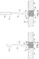
- the supporting framework 350 comprises a plurality of deployable members 352 a - 352 d , each having a proximal end with first and second segments 353 a and 353 b , and a distal end 354 .
- the supporting framework 350 may be formed of a single wire 351 , or a plurality of wires, that are bent in the configuration shown in FIG. 10 , whereby the plurality of deployable members 352 a - 352 d extend distally from a central portion 365 .
- each of the distal ends 354 comprises an eyelet 357 , which may be formed where the wire 351 loops over itself.
- an eyelet 363 may be formed in a region where the deployable member 352 a transitions into the deployable member 352 d , as shown in FIG. 10 .
- the graft member 80 is coupled to the supporting framework 350 using sutures 359 , which preferably are looped around each of the eyelets 357 of the deployable members 352 a - 352 d , as well as the eyelet 363 .
- the supporting framework 350 comprises a delivery state, in which the supporting framework 350 may be delivered through the insertion tool 170 as described above, or alternatively, directly though a trocar.
- the plurality of deployable members 352 a - 352 d are generally parallel to one another.
- each of the plurality of deployable members 352 a - 352 d comprises a shape-memory material, such as a nickel-titanium alloy (nitinol), or alternatively other metals and alloys that are biased, such that they may be restrained prior to deployment, but are inclined to return to their relaxed, expanded configuration upon deployment, as described above.
- one of the anchors 20 , 120 or 220 is positioned and deployed securely within the opening 75 , as described in detail above.
- the first and second tethers 32 and 34 extend away from the anchor that is deployed within the opening 75 .
- the graft member 80 comprises first and second bores 381 and 382 , which permit advancement of the graft member 80 over the first and second tethers 30 and 32 , as described above.
- the graft member 80 is advanced over the first and second tethers 30 and 32 with each of the plurality of deployable members 352 a - 352 d of the supporting framework 350 in the compressed delivery state.
- the plurality of deployable members 352 a - 352 d are generally parallel to one another, preferably with the distal ends 354 of each of the plurality of deployable members 352 a - 352 d facing proximally.
- the selected anchor 20 , 120 or 220 is ejected from the insertion tool, allowing the plurality of deployable members 352 a - 352 d to assume the expanded deployed shape, as shown in FIG. 11 .
- the plurality of deployable members 352 a - 352 d are sized such that an overall width of the supporting framework 350 in the expanded state, measured as the longitudinal distance between the distal end 354 of the deployable member 352 a and the distal end 354 of the opposing deployable member 352 c , is about 2-4 times greater than the diameter of the opening 75 , thereby ensuring that the graft member 80 sufficiently covers the opening 75 .
- a suture tying device may be used to tie the first and second tethers 30 and 32 together in a manner that holds the graft member 80 adjacent to the tissue 74 and the selected anchor 20 , 120 or 220 .
- the anchor 420 comprises a plurality of deployable members 422 a - 422 d , each having a proximal end 423 and a distal end 424 .
- the distal ends 424 of the plurality of deployable members 422 a - 422 d may be joined at a base 428 .
- One or more tethers such as first and second tethers 30 and 32 of FIGS. 1-5 (illustrated as one tether 430 in FIG. 12 ) may be coupled to the anchor 420 , e.g., attached to the base 428 and extending proximally therefrom.
- the anchor 420 comprises a delivery state in which the anchor 420 may be delivered through a suitable insertion tool, as generally described above with regard to the embodiment of FIGS. 6-7 .
- the anchor 420 when deployed from the insertion tool, may assume the configuration shown in FIG. 12 .
- an expansion member such as exemplary balloon 450 , may be used to radially expand the plurality of deployable members 422 a - 422 d into engagement with tissue 74 surrounding the opening 75 .
- the plurality of deployable members 422 a - 422 d then assume an expanded deployed state as shown in FIG. 13 , where the plurality of deployable members 422 a - 422 d securely engage tissue.
- Barbs 455 may be provided near each of the proximal ends 423 , as shown in FIGS. 12-13 , to promote a secure attachment.
- the graft member 80 above is advanced distally over the tethers towards the anchor 420 , as generally described above with regard to the method of FIGS. 4-5 and FIGS. 6-7 .
- the anchors and/or supporting frameworks may comprise a bioresorbable material, such as L-lactide/caprolactone copolymers-PLC 8516 (85/15 L-Lactide/caprolactone) as well as PLC 7015 (70/30 L-Lactide/caprolactone), which are supplied by Purac Biomaterials, Gorinchem, Netherlands.
- Other potential bioresorbable polymers include PLGA, PLA, PGA, PLLA, and the like.
- the anchors and supporting frameworks may comprise non-resorbable materials, including but not limited to materials disclosed herein.
- the graft member 80 may comprise a material that can be integrated with the surrounding tissue.
- the graft member 80 may comprise an adhesion barrier to facilitate coupling to tissue.
- a magnetic arrangement may be used, with one magnet coupled to the graft member 80 and an opposing magnet coupled to the anchor to hold the graft member 80 and the anchor in proximity to each other.
- any of the anchors described herein may be deployed distal to the opening 75 , in which case the anchors can assume a diameter larger than the opening 75 and provide anchoring functionality just distal to the tissue 74 with the same method steps otherwise being performed as shown herein.
- an anchor may be disposed at least partially within the opening 75 and simultaneously at least partially distal to the opening 75 in any of the embodiments shown.
- the systems disclosed herein may be useful in many other procedures. Solely by way of example, the systems may be used to treat perforations in a visceral wall, such as the stomach wall. Further, the systems 20 may be used to secure a graft member to tissue for reconstructing local tissue, and the like.
Landscapes
- Health & Medical Sciences (AREA)
- Life Sciences & Earth Sciences (AREA)
- Public Health (AREA)
- Cardiology (AREA)
- Veterinary Medicine (AREA)
- Engineering & Computer Science (AREA)
- Biomedical Technology (AREA)
- Heart & Thoracic Surgery (AREA)
- Surgery (AREA)
- General Health & Medical Sciences (AREA)
- Animal Behavior & Ethology (AREA)
- Molecular Biology (AREA)
- Medical Informatics (AREA)
- Nuclear Medicine, Radiotherapy & Molecular Imaging (AREA)
- Oral & Maxillofacial Surgery (AREA)
- Transplantation (AREA)
- Vascular Medicine (AREA)
- Surgical Instruments (AREA)
Abstract
Description
Claims (20)
Priority Applications (2)
| Application Number | Priority Date | Filing Date | Title |
|---|---|---|---|
| US15/099,068 US10568614B2 (en) | 2010-04-29 | 2016-04-14 | Systems and methods for facilitating closure of bodily openings |
| US15/800,437 US20180049731A1 (en) | 2010-04-29 | 2017-11-01 | Closing device for tissue openings |
Applications Claiming Priority (4)
| Application Number | Priority Date | Filing Date | Title |
|---|---|---|---|
| US34343510P | 2010-04-29 | 2010-04-29 | |
| US37924310P | 2010-09-01 | 2010-09-01 | |
| US13/096,433 US20120016409A1 (en) | 2010-04-29 | 2011-04-28 | Systems and methods for facilitating closure of bodily openings |
| US15/099,068 US10568614B2 (en) | 2010-04-29 | 2016-04-14 | Systems and methods for facilitating closure of bodily openings |
Related Parent Applications (2)
| Application Number | Title | Priority Date | Filing Date |
|---|---|---|---|
| US13/096,433 Division US20120016409A1 (en) | 2010-04-29 | 2011-04-28 | Systems and methods for facilitating closure of bodily openings |
| US13/096,433 Continuation US20120016409A1 (en) | 2010-04-29 | 2011-04-28 | Systems and methods for facilitating closure of bodily openings |
Related Child Applications (1)
| Application Number | Title | Priority Date | Filing Date |
|---|---|---|---|
| PCT/US2015/037378 Continuation-In-Part WO2016003722A1 (en) | 2010-04-29 | 2015-06-24 | Expandable mesh with locking feature |
Publications (2)
| Publication Number | Publication Date |
|---|---|
| US20160228110A1 US20160228110A1 (en) | 2016-08-11 |
| US10568614B2 true US10568614B2 (en) | 2020-02-25 |
Family
ID=44211038
Family Applications (2)
| Application Number | Title | Priority Date | Filing Date |
|---|---|---|---|
| US13/096,433 Abandoned US20120016409A1 (en) | 2010-04-29 | 2011-04-28 | Systems and methods for facilitating closure of bodily openings |
| US15/099,068 Active 2033-02-24 US10568614B2 (en) | 2010-04-29 | 2016-04-14 | Systems and methods for facilitating closure of bodily openings |
Family Applications Before (1)
| Application Number | Title | Priority Date | Filing Date |
|---|---|---|---|
| US13/096,433 Abandoned US20120016409A1 (en) | 2010-04-29 | 2011-04-28 | Systems and methods for facilitating closure of bodily openings |
Country Status (3)
| Country | Link |
|---|---|
| US (2) | US20120016409A1 (en) |
| EP (1) | EP2563231A1 (en) |
| WO (1) | WO2011137224A1 (en) |
Families Citing this family (28)
| Publication number | Priority date | Publication date | Assignee | Title |
|---|---|---|---|---|
| CN101242785B (en) | 2005-06-20 | 2010-11-03 | 苏图诺有限公司 | Device for applying knots to sutures |
| US8246636B2 (en) | 2007-03-29 | 2012-08-21 | Nobles Medical Technologies, Inc. | Suturing devices and methods for closing a patent foramen ovale |
| JP5848125B2 (en) | 2008-05-09 | 2016-01-27 | ノーブルズ メディカル テクノロジーズ、インコーポレイテッド | Suture device and method for suturing anatomic valves |
| US10568628B2 (en) | 2017-05-23 | 2020-02-25 | Muffin Incorporated | Closing device for tissue openings |
| CN103889345B (en) | 2011-04-15 | 2016-10-19 | 心脏缝合有限公司 | Suturing device and method for suturing anatomical flaps |
| US9339365B2 (en) | 2011-07-07 | 2016-05-17 | David D. Park | Device and method for delivering grafts |
| EP3597115B1 (en) | 2012-05-11 | 2025-01-15 | Heartstitch, Inc. | Suturing devices for suturing an anatomic structure |
| US9445797B2 (en) * | 2012-09-13 | 2016-09-20 | Medtronic, Inc. | Percutaneous atrial and ventricular septal defect closure device |
| WO2014152750A1 (en) * | 2013-03-15 | 2014-09-25 | Avon Products, Inc | Compositions with enhanced depth of color |
| CN203169800U (en) * | 2013-04-25 | 2013-09-04 | 潘湘斌 | Treatment guide device |
| US10828022B2 (en) | 2013-07-02 | 2020-11-10 | Med-Venture Investments, Llc | Suturing devices and methods for suturing an anatomic structure |
| US10512458B2 (en) | 2013-12-06 | 2019-12-24 | Med-Venture Investments, Llc | Suturing methods and apparatuses |
| ES2896177T3 (en) | 2014-03-06 | 2022-02-24 | Bard Inc C R | hernia repair patch |
| EP3160362B1 (en) * | 2014-06-30 | 2023-01-04 | Cook Medical Technologies LLC | Expandable mesh with locking feature |
| US10178993B2 (en) | 2014-07-11 | 2019-01-15 | Cardio Medical Solutions, Inc. | Device and method for assisting end-to-side anastomosis |
| US10172700B2 (en) * | 2014-12-01 | 2019-01-08 | C.R. Bard, Inc. | Prosthesis for repairing a hernia defect |
| EP3799830B1 (en) | 2015-12-28 | 2023-08-02 | C. R. Bard, Inc. | Prosthesis for repairing a hernia defect |
| US10687801B2 (en) | 2016-04-11 | 2020-06-23 | Nobles Medical Technologies Ii, Inc. | Suture spools for tissue suturing device |
| EP3300669A1 (en) * | 2016-09-29 | 2018-04-04 | Universität Zürich | Device and method for sealing a membrane |
| WO2018236822A1 (en) | 2017-06-19 | 2018-12-27 | Heartstitch, Inc. | SUTURE DEVICES AND METHODS OF SUTURING OPENING IN HEART APEX |
| EP4115818B1 (en) | 2017-06-19 | 2026-02-04 | Heartstitch, Inc. | Suturing systems for suturing body tissue |
| EP3648677B1 (en) | 2017-07-06 | 2025-02-26 | Park Surgical Innovations, Llc | Device for delivering grafts at a surgical site |
| US11090145B2 (en) | 2017-07-06 | 2021-08-17 | Park Surgical Innovations, Llc | Device for delivering grafts at a surgical site and method |
| WO2019035095A1 (en) | 2017-08-18 | 2019-02-21 | Nobles Medical Technologies Ii, Inc. | Apparatus for applying a knot to a suture |
| US10624729B2 (en) * | 2017-10-12 | 2020-04-21 | C.R. Bard, Inc. | Repair prosthetic curl mitigation |
| CN108030570B (en) * | 2017-12-20 | 2020-03-24 | 南方医科大学南方医院 | Patch placer |
| US11642206B1 (en) * | 2022-11-17 | 2023-05-09 | King Faisal University | System and method for laparoscopic repair of abdominal wall hernia using umbrella mesh |
| CA3271330A1 (en) * | 2024-04-26 | 2025-11-29 | Morning Lily Surgical Innovations Inc. | Fabric-like hernia plug |
Citations (35)
| Publication number | Priority date | Publication date | Assignee | Title |
|---|---|---|---|---|
| US3416534A (en) | 1966-04-11 | 1968-12-17 | Gen Electric | Body organ electrode |
| US4368730A (en) | 1981-02-12 | 1983-01-18 | Nigel Sharrock | Intravenous catheter |
| US4907598A (en) | 1987-05-05 | 1990-03-13 | Alberto Bauer | Guillotine biopsy needle provided with flexible stylus and cannula |
| US5081997A (en) | 1989-03-09 | 1992-01-21 | Vance Products Incorporated | Echogenic devices, material and method |
| US5116357A (en) | 1990-10-11 | 1992-05-26 | Eberbach Mark A | Hernia plug and introducer apparatus |
| US5122155A (en) | 1990-10-11 | 1992-06-16 | Eberbach Mark A | Hernia repair apparatus and method of use |
| US5228451A (en) | 1990-05-10 | 1993-07-20 | Symbiosis Corporation | Biopsy forceps device having stiff distal end |
| US5258000A (en) | 1991-11-25 | 1993-11-02 | Cook Incorporated | Tissue aperture repair device |
| US5308324A (en) | 1989-01-09 | 1994-05-03 | Pilot Cardiovascular Systems, Inc. | Steerable medical device |
| US5312435A (en) | 1993-05-17 | 1994-05-17 | Kensey Nash Corporation | Fail predictable, reinforced anchor for hemostatic puncture closure |
| US5366460A (en) | 1990-10-11 | 1994-11-22 | Cook Incorporated | Apparatus and method for laparoscope hernia repair |
| US5372587A (en) | 1989-01-09 | 1994-12-13 | Pilot Cariovascular Systems, Inc. | Steerable medical device |
| US5397331A (en) | 1991-11-25 | 1995-03-14 | Cook Incorporated | Supporting device and apparatus for inserting the device |
| US5545178A (en) | 1994-04-29 | 1996-08-13 | Kensey Nash Corporation | System for closing a percutaneous puncture formed by a trocar to prevent tissue at the puncture from herniating |
| US5549633A (en) | 1994-08-24 | 1996-08-27 | Kensey Nash Corporation | Apparatus and methods of use for preventing blood seepage at a percutaneous puncture site |
| US5607407A (en) | 1994-05-09 | 1997-03-04 | Tolkoff; Marc J. | Catheter assembly |
| US5662681A (en) | 1996-04-23 | 1997-09-02 | Kensey Nash Corporation | Self locking closure for sealing percutaneous punctures |
| US5700277A (en) | 1993-06-04 | 1997-12-23 | Kensey Nash Corporation | Hemostatic vessel puncture closure with filament lock |
| US5743891A (en) | 1996-10-25 | 1998-04-28 | Act Medical, Inc. | Subcutaneous safety catheter assembly |
| JPH1176403A (en) | 1997-07-11 | 1999-03-23 | Olympus Optical Co Ltd | Surgical treatment instrument |
| US5906594A (en) | 1997-01-08 | 1999-05-25 | Symbiosis Corporation | Endoscopic infusion needle having dual distal stops |
| US6210377B1 (en) | 1996-07-09 | 2001-04-03 | Asahi Kogaku Kogyo Kabushiki Kaisha | Treatment accessory for an endoscope |
| US6456874B1 (en) | 2000-03-13 | 2002-09-24 | Arrow International Inc. | Instrument for delivery of anaesthetic drug |
| US20030004579A1 (en) | 2001-06-28 | 2003-01-02 | Ethicon, Inc. | Hernia repair prosthesis and methods for making same |
| US6689122B2 (en) | 2000-05-17 | 2004-02-10 | Olympus Corporation | Endoscopic instrument |
| US20040049231A1 (en) | 2000-03-13 | 2004-03-11 | Fred Hafer | Instrument and method for delivery of anaesthetic drugs |
| US20040098044A1 (en) | 1989-05-29 | 2004-05-20 | Van De Moer Wouter Matthijs Muijs | Sealing device |
| US20050070948A1 (en) | 2003-09-26 | 2005-03-31 | Kirsteins Andrew E. | Subcutaneous insertion devices and methods for stimulating subcutaneous regions of patients |
| US7488347B1 (en) | 2005-01-06 | 2009-02-10 | Medicine Lodge, Inc. | Transosseous graft retention system and method |
| US20090062844A1 (en) | 2007-08-27 | 2009-03-05 | Cook Incorporated | Spider pfo closure device |
| US20090204133A1 (en) | 2006-04-27 | 2009-08-13 | Biophan Europe Gmbh | Occluder |
| US20090204130A1 (en) | 2008-02-13 | 2009-08-13 | Sergey Veniaminovich Kantsevoy | Method of Performing Transgastric Ventral Hernia Repair and Tissue Anchors and Deployment Devices Therefor |
| US20090287229A1 (en) | 2008-05-19 | 2009-11-19 | Ams Research Corporation | Collapsible Tissue Anchor Device and Method |
| US7897167B2 (en) | 2005-06-21 | 2011-03-01 | Cook Incorporated | Implantable graft to close a fistula |
| US8277481B2 (en) | 2003-12-26 | 2012-10-02 | Terumo Kabushiki Kaisha | Tissue closure and tissue closing device |
Family Cites Families (2)
| Publication number | Priority date | Publication date | Assignee | Title |
|---|---|---|---|---|
| SK22499A3 (en) | 1996-08-23 | 1999-10-08 | Cook Biotech Inc | Graft prosthesis, materials and methods |
| GB2595848B (en) | 2020-06-01 | 2023-04-19 | Altro Ltd | Improvements in or relating to organic material |
-
2011
- 2011-04-28 EP EP11718857A patent/EP2563231A1/en not_active Withdrawn
- 2011-04-28 US US13/096,433 patent/US20120016409A1/en not_active Abandoned
- 2011-04-28 WO PCT/US2011/034285 patent/WO2011137224A1/en not_active Ceased
-
2016
- 2016-04-14 US US15/099,068 patent/US10568614B2/en active Active
Patent Citations (37)
| Publication number | Priority date | Publication date | Assignee | Title |
|---|---|---|---|---|
| US3416534A (en) | 1966-04-11 | 1968-12-17 | Gen Electric | Body organ electrode |
| US4368730A (en) | 1981-02-12 | 1983-01-18 | Nigel Sharrock | Intravenous catheter |
| US4907598A (en) | 1987-05-05 | 1990-03-13 | Alberto Bauer | Guillotine biopsy needle provided with flexible stylus and cannula |
| US5308324A (en) | 1989-01-09 | 1994-05-03 | Pilot Cardiovascular Systems, Inc. | Steerable medical device |
| US5372587A (en) | 1989-01-09 | 1994-12-13 | Pilot Cariovascular Systems, Inc. | Steerable medical device |
| US5081997A (en) | 1989-03-09 | 1992-01-21 | Vance Products Incorporated | Echogenic devices, material and method |
| US20040098044A1 (en) | 1989-05-29 | 2004-05-20 | Van De Moer Wouter Matthijs Muijs | Sealing device |
| US5228451A (en) | 1990-05-10 | 1993-07-20 | Symbiosis Corporation | Biopsy forceps device having stiff distal end |
| US5116357A (en) | 1990-10-11 | 1992-05-26 | Eberbach Mark A | Hernia plug and introducer apparatus |
| US5366460A (en) | 1990-10-11 | 1994-11-22 | Cook Incorporated | Apparatus and method for laparoscope hernia repair |
| US5122155A (en) | 1990-10-11 | 1992-06-16 | Eberbach Mark A | Hernia repair apparatus and method of use |
| US5258000A (en) | 1991-11-25 | 1993-11-02 | Cook Incorporated | Tissue aperture repair device |
| US5397331A (en) | 1991-11-25 | 1995-03-14 | Cook Incorporated | Supporting device and apparatus for inserting the device |
| US5312435A (en) | 1993-05-17 | 1994-05-17 | Kensey Nash Corporation | Fail predictable, reinforced anchor for hemostatic puncture closure |
| US5700277A (en) | 1993-06-04 | 1997-12-23 | Kensey Nash Corporation | Hemostatic vessel puncture closure with filament lock |
| US5545178A (en) | 1994-04-29 | 1996-08-13 | Kensey Nash Corporation | System for closing a percutaneous puncture formed by a trocar to prevent tissue at the puncture from herniating |
| US5607407A (en) | 1994-05-09 | 1997-03-04 | Tolkoff; Marc J. | Catheter assembly |
| US5728114A (en) | 1994-08-24 | 1998-03-17 | Kensey Nash Corporation | Apparatus and methods of use for preventing blood seepage at a percutaneous puncture site |
| US5549633A (en) | 1994-08-24 | 1996-08-27 | Kensey Nash Corporation | Apparatus and methods of use for preventing blood seepage at a percutaneous puncture site |
| US5662681A (en) | 1996-04-23 | 1997-09-02 | Kensey Nash Corporation | Self locking closure for sealing percutaneous punctures |
| US6210377B1 (en) | 1996-07-09 | 2001-04-03 | Asahi Kogaku Kogyo Kabushiki Kaisha | Treatment accessory for an endoscope |
| US5743891A (en) | 1996-10-25 | 1998-04-28 | Act Medical, Inc. | Subcutaneous safety catheter assembly |
| US5906594A (en) | 1997-01-08 | 1999-05-25 | Symbiosis Corporation | Endoscopic infusion needle having dual distal stops |
| JPH1176403A (en) | 1997-07-11 | 1999-03-23 | Olympus Optical Co Ltd | Surgical treatment instrument |
| US6126633A (en) | 1997-07-11 | 2000-10-03 | Olympus Optical Co., Ltd. | Surgical instrument |
| US20040049231A1 (en) | 2000-03-13 | 2004-03-11 | Fred Hafer | Instrument and method for delivery of anaesthetic drugs |
| US6456874B1 (en) | 2000-03-13 | 2002-09-24 | Arrow International Inc. | Instrument for delivery of anaesthetic drug |
| US6689122B2 (en) | 2000-05-17 | 2004-02-10 | Olympus Corporation | Endoscopic instrument |
| US20030004579A1 (en) | 2001-06-28 | 2003-01-02 | Ethicon, Inc. | Hernia repair prosthesis and methods for making same |
| US20050070948A1 (en) | 2003-09-26 | 2005-03-31 | Kirsteins Andrew E. | Subcutaneous insertion devices and methods for stimulating subcutaneous regions of patients |
| US8277481B2 (en) | 2003-12-26 | 2012-10-02 | Terumo Kabushiki Kaisha | Tissue closure and tissue closing device |
| US7488347B1 (en) | 2005-01-06 | 2009-02-10 | Medicine Lodge, Inc. | Transosseous graft retention system and method |
| US7897167B2 (en) | 2005-06-21 | 2011-03-01 | Cook Incorporated | Implantable graft to close a fistula |
| US20090204133A1 (en) | 2006-04-27 | 2009-08-13 | Biophan Europe Gmbh | Occluder |
| US20090062844A1 (en) | 2007-08-27 | 2009-03-05 | Cook Incorporated | Spider pfo closure device |
| US20090204130A1 (en) | 2008-02-13 | 2009-08-13 | Sergey Veniaminovich Kantsevoy | Method of Performing Transgastric Ventral Hernia Repair and Tissue Anchors and Deployment Devices Therefor |
| US20090287229A1 (en) | 2008-05-19 | 2009-11-19 | Ams Research Corporation | Collapsible Tissue Anchor Device and Method |
Non-Patent Citations (5)
| Title |
|---|
| Communication pursuant to Rules 161(1) and 162EPC for European Patent Application No. 11718857.3 dated Jan. 7, 2013 (2 pgs). |
| International Preliminary Report on Patentability for PCT/US2011/034285 dated Oct. 30, 2012 (8 pgs). |
| International Search Report for PCT/US2011/034285 dated Jul. 8, 2011 (6 pgs). |
| Response to Communication pursuant to Rules (161(1) and 162 EPC for European Patent Application No. 11718857.3 dated Jul. 16, 2013 (15 pgs). |
| Written Opinion for PCT/US2011/034285 (6 pgs). |
Also Published As
| Publication number | Publication date |
|---|---|
| US20160228110A1 (en) | 2016-08-11 |
| US20120016409A1 (en) | 2012-01-19 |
| EP2563231A1 (en) | 2013-03-06 |
| WO2011137224A1 (en) | 2011-11-03 |
Similar Documents
| Publication | Publication Date | Title |
|---|---|---|
| US10568614B2 (en) | Systems and methods for facilitating closure of bodily openings | |
| US8500760B2 (en) | Retractable tacking device | |
| AU2009335902B2 (en) | Variable thickness tacking devices and methods of delivery and deployment | |
| US8192461B2 (en) | Methods for facilitating closure of a bodily opening using one or more tacking devices | |
| US20180049731A1 (en) | Closing device for tissue openings | |
| US20240138970A1 (en) | Expandable mesh with locking feature | |
| US20110245851A1 (en) | Removable medical device having at least one patch member | |
| US20120209322A1 (en) | Tacking device | |
| US20100069924A1 (en) | Methods for achieving serosa-to-serosa closure of a bodily opening using one or more tacking devices | |
| US9345476B2 (en) | Tacking device and methods of deployment |
Legal Events
| Date | Code | Title | Description |
|---|---|---|---|
| AS | Assignment |
Owner name: COOK MEDICAL TECHNOLOGIES LLC, INDIANA Free format text: ASSIGNMENT OF ASSIGNORS INTEREST;ASSIGNOR:WILSON-COOK MEDICAL;REEL/FRAME:038567/0375 Effective date: 20110915 Owner name: COOK MEDICAL TECHNOLOGIES LLC, INDIANA Free format text: ASSIGNMENT OF ASSIGNORS INTEREST;ASSIGNOR:SHERWINTER, DANNY AZRIEL;REEL/FRAME:038567/0540 Effective date: 20110919 Owner name: WILSON-COOK MEDICAL, INC., NORTH CAROLINA Free format text: ASSIGNMENT OF ASSIGNORS INTEREST;ASSIGNORS:SIGMON, JOHN CROWDER, JR.;SURTI, VIHAR C.;REEL/FRAME:038567/0275 Effective date: 20110913 |
|
| STPP | Information on status: patent application and granting procedure in general |
Free format text: RESPONSE TO NON-FINAL OFFICE ACTION ENTERED AND FORWARDED TO EXAMINER |
|
| STPP | Information on status: patent application and granting procedure in general |
Free format text: FINAL REJECTION MAILED |
|
| STPP | Information on status: patent application and granting procedure in general |
Free format text: RESPONSE AFTER FINAL ACTION FORWARDED TO EXAMINER |
|
| STPP | Information on status: patent application and granting procedure in general |
Free format text: ADVISORY ACTION MAILED |
|
| STPP | Information on status: patent application and granting procedure in general |
Free format text: DOCKETED NEW CASE - READY FOR EXAMINATION |
|
| STPP | Information on status: patent application and granting procedure in general |
Free format text: NOTICE OF ALLOWANCE MAILED -- APPLICATION RECEIVED IN OFFICE OF PUBLICATIONS |
|
| STPP | Information on status: patent application and granting procedure in general |
Free format text: PUBLICATIONS -- ISSUE FEE PAYMENT VERIFIED |
|
| STCF | Information on status: patent grant |
Free format text: PATENTED CASE |
|
| MAFP | Maintenance fee payment |
Free format text: PAYMENT OF MAINTENANCE FEE, 4TH YEAR, LARGE ENTITY (ORIGINAL EVENT CODE: M1551); ENTITY STATUS OF PATENT OWNER: LARGE ENTITY Year of fee payment: 4 |
|
| AS | Assignment |
Owner name: WILMINGTON TRUST, NATIONAL ASSOCIATION, AS COLLATERAL AGENT, DELAWARE Free format text: SECURITY INTEREST;ASSIGNOR:COOK MEDICAL TECHNOLOGIES LLC;REEL/FRAME:066700/0277 Effective date: 20240227 |