US10566634B2 - Fuel cell unit and fuel cell array - Google Patents
Fuel cell unit and fuel cell array Download PDFInfo
- Publication number
- US10566634B2 US10566634B2 US15/894,627 US201815894627A US10566634B2 US 10566634 B2 US10566634 B2 US 10566634B2 US 201815894627 A US201815894627 A US 201815894627A US 10566634 B2 US10566634 B2 US 10566634B2
- Authority
- US
- United States
- Prior art keywords
- fuel cell
- fuel
- electrode layer
- layer
- solid electrolyte
- Prior art date
- Legal status (The legal status is an assumption and is not a legal conclusion. Google has not performed a legal analysis and makes no representation as to the accuracy of the status listed.)
- Active, expires
Links
Images


Classifications
-
- H—ELECTRICITY
- H01—ELECTRIC ELEMENTS
- H01M—PROCESSES OR MEANS, e.g. BATTERIES, FOR THE DIRECT CONVERSION OF CHEMICAL ENERGY INTO ELECTRICAL ENERGY
- H01M8/00—Fuel cells; Manufacture thereof
- H01M8/002—Shape, form of a fuel cell
- H01M8/004—Cylindrical, tubular or wound
-
- H—ELECTRICITY
- H01—ELECTRIC ELEMENTS
- H01M—PROCESSES OR MEANS, e.g. BATTERIES, FOR THE DIRECT CONVERSION OF CHEMICAL ENERGY INTO ELECTRICAL ENERGY
- H01M8/00—Fuel cells; Manufacture thereof
- H01M8/02—Details
- H01M8/0202—Collectors; Separators, e.g. bipolar separators; Interconnectors
-
- H—ELECTRICITY
- H01—ELECTRIC ELEMENTS
- H01M—PROCESSES OR MEANS, e.g. BATTERIES, FOR THE DIRECT CONVERSION OF CHEMICAL ENERGY INTO ELECTRICAL ENERGY
- H01M8/00—Fuel cells; Manufacture thereof
- H01M8/02—Details
- H01M8/0202—Collectors; Separators, e.g. bipolar separators; Interconnectors
- H01M8/0204—Non-porous and characterised by the material
- H01M8/0206—Metals or alloys
- H01M8/0208—Alloys
- H01M8/021—Alloys based on iron
-
- H—ELECTRICITY
- H01—ELECTRIC ELEMENTS
- H01M—PROCESSES OR MEANS, e.g. BATTERIES, FOR THE DIRECT CONVERSION OF CHEMICAL ENERGY INTO ELECTRICAL ENERGY
- H01M8/00—Fuel cells; Manufacture thereof
- H01M8/02—Details
- H01M8/0202—Collectors; Separators, e.g. bipolar separators; Interconnectors
- H01M8/0247—Collectors; Separators, e.g. bipolar separators; Interconnectors characterised by the form
- H01M8/0252—Collectors; Separators, e.g. bipolar separators; Interconnectors characterised by the form tubular
-
- H—ELECTRICITY
- H01—ELECTRIC ELEMENTS
- H01M—PROCESSES OR MEANS, e.g. BATTERIES, FOR THE DIRECT CONVERSION OF CHEMICAL ENERGY INTO ELECTRICAL ENERGY
- H01M8/00—Fuel cells; Manufacture thereof
- H01M8/02—Details
- H01M8/0271—Sealing or supporting means around electrodes, matrices or membranes
- H01M8/028—Sealing means characterised by their material
- H01M8/0282—Inorganic material
-
- H—ELECTRICITY
- H01—ELECTRIC ELEMENTS
- H01M—PROCESSES OR MEANS, e.g. BATTERIES, FOR THE DIRECT CONVERSION OF CHEMICAL ENERGY INTO ELECTRICAL ENERGY
- H01M8/00—Fuel cells; Manufacture thereof
- H01M8/02—Details
- H01M8/0271—Sealing or supporting means around electrodes, matrices or membranes
- H01M8/028—Sealing means characterised by their material
- H01M8/0284—Organic resins; Organic polymers
-
- H—ELECTRICITY
- H01—ELECTRIC ELEMENTS
- H01M—PROCESSES OR MEANS, e.g. BATTERIES, FOR THE DIRECT CONVERSION OF CHEMICAL ENERGY INTO ELECTRICAL ENERGY
- H01M8/00—Fuel cells; Manufacture thereof
- H01M8/10—Fuel cells with solid electrolytes
- H01M8/1007—Fuel cells with solid electrolytes with both reactants being gaseous or vaporised
-
- H—ELECTRICITY
- H01—ELECTRIC ELEMENTS
- H01M—PROCESSES OR MEANS, e.g. BATTERIES, FOR THE DIRECT CONVERSION OF CHEMICAL ENERGY INTO ELECTRICAL ENERGY
- H01M8/00—Fuel cells; Manufacture thereof
- H01M8/10—Fuel cells with solid electrolytes
- H01M8/12—Fuel cells with solid electrolytes operating at high temperature, e.g. with stabilised ZrO2 electrolyte
-
- H—ELECTRICITY
- H01—ELECTRIC ELEMENTS
- H01M—PROCESSES OR MEANS, e.g. BATTERIES, FOR THE DIRECT CONVERSION OF CHEMICAL ENERGY INTO ELECTRICAL ENERGY
- H01M8/00—Fuel cells; Manufacture thereof
- H01M8/24—Grouping of fuel cells, e.g. stacking of fuel cells
- H01M8/241—Grouping of fuel cells, e.g. stacking of fuel cells with solid or matrix-supported electrolytes
- H01M8/2425—High-temperature cells with solid electrolytes
- H01M8/243—Grouping of unit cells of tubular or cylindrical configuration
-
- H—ELECTRICITY
- H01—ELECTRIC ELEMENTS
- H01M—PROCESSES OR MEANS, e.g. BATTERIES, FOR THE DIRECT CONVERSION OF CHEMICAL ENERGY INTO ELECTRICAL ENERGY
- H01M8/00—Fuel cells; Manufacture thereof
- H01M8/10—Fuel cells with solid electrolytes
- H01M8/12—Fuel cells with solid electrolytes operating at high temperature, e.g. with stabilised ZrO2 electrolyte
- H01M2008/1293—Fuel cells with solid oxide electrolytes
-
- H—ELECTRICITY
- H01—ELECTRIC ELEMENTS
- H01M—PROCESSES OR MEANS, e.g. BATTERIES, FOR THE DIRECT CONVERSION OF CHEMICAL ENERGY INTO ELECTRICAL ENERGY
- H01M8/00—Fuel cells; Manufacture thereof
- H01M8/06—Combination of fuel cells with means for production of reactants or for treatment of residues
- H01M8/0606—Combination of fuel cells with means for production of reactants or for treatment of residues with means for production of gaseous reactants
- H01M8/0612—Combination of fuel cells with means for production of reactants or for treatment of residues with means for production of gaseous reactants from carbon-containing material
- H01M8/0625—Combination of fuel cells with means for production of reactants or for treatment of residues with means for production of gaseous reactants from carbon-containing material in a modular combined reactor/fuel cell structure
- H01M8/0631—Reactor construction specially adapted for combination reactor/fuel cell
-
- Y—GENERAL TAGGING OF NEW TECHNOLOGICAL DEVELOPMENTS; GENERAL TAGGING OF CROSS-SECTIONAL TECHNOLOGIES SPANNING OVER SEVERAL SECTIONS OF THE IPC; TECHNICAL SUBJECTS COVERED BY FORMER USPC CROSS-REFERENCE ART COLLECTIONS [XRACs] AND DIGESTS
- Y02—TECHNOLOGIES OR APPLICATIONS FOR MITIGATION OR ADAPTATION AGAINST CLIMATE CHANGE
- Y02E—REDUCTION OF GREENHOUSE GAS [GHG] EMISSIONS, RELATED TO ENERGY GENERATION, TRANSMISSION OR DISTRIBUTION
- Y02E60/00—Enabling technologies; Technologies with a potential or indirect contribution to GHG emissions mitigation
- Y02E60/30—Hydrogen technology
- Y02E60/50—Fuel cells
Definitions
- the present invention relates to a fuel cell unit and a fuel cell array.
- the present invention relates to a fuel cell unit that uses a solid oxide fuel cell to generate electricity by reforming a starting material gas to obtain a fuel gas and then by reacting the fuel gas with an oxidant gas, as well as to a fuel cell array that uses the fuel cell units.
- a solid oxide fuel cell (SOFC) device is an electricity-generating device that employs an oxide ion conducting solid electrolyte layer that serves as an electrolyte.
- a plurality of fuel cells with electrodes attached to both sides of these layers are arranged inside a module, and a fuel gas is supplied to one of the electrodes (fuel electrode) of the fuel cell, while an oxidant gas (air, oxygen, or the like) is supplied to the other electrode (air electrode), causing an electricity-generating reaction, thereby extracting electrical power generated by electricity-generating reaction.
- solid oxide fuel cells operate at relatively high temperature on the order of 700-1,000° C.
- a gas seal is typically provided in such a solid oxide fuel cell device in order to isolate the channel for supplying the fuel gas to the fuel electrodes from the channel for supplying the oxidant gas to the air electrodes.
- a solid oxide fuel cell device according to Patent Reference 1 wherein a plurality of cylindrical fuel cells (also referred to as a tubular fuel cells) are arranged and electrically connected, conductive caps are attached to the top ends and to the bottom ends of the fuel cells, and the device is structured so that electrical current is extracted from the fuel electrode layers of the fuel cells to outside of the fuel cells via these caps.
- the fuel gas is supplied to an internal flow channel of each of the fuel cells from the fuel gas flow-through ports of the caps attached to the bottom ends of the fuel cells.
- Patent Reference 1 The end structure of the tubular fuel cell of Patent Reference 1 had a problem in that if the fuel gas leaks to the outside, without passing through the fuel gas flow-through port of the cap, hydrogen in the leaked fuel gas reduces the air electrode located on the outside of the fuel cell, causing a degradation of performance. Therefore, in Patent Reference 1, in order to prevent leakage of fuel gas (hydrogen) to the air electrode side, an air-tight seal is formed using a dense material (glass) in addition to a silver seal for providing a conductive connection between the fuel cell and the cap.
- a dense material glass
- Patent Reference 1 WO2013/047667
- Patent Reference 2 Japanese Patent Application Kokai Publication No. 2011-99159
- the above-described solid oxide fuel cell device operates in high-temperature environments on the order of 700-1,000° C., it is difficult to avoid using silver or conductive materials having silver as the primary constituent, from the standpoint of conductive performance in conductive connections between the fuel cells and the caps, as well as from the overall standpoints of thermal resistance, oxidative resistance, flexibility, strength, and the like.
- a dense material such as glass
- the oxygen also passes through the silver material, and reacts with the hydrogen that passes from the fuel gas into the silver material, resulting in forming water vapor in the silver material. Formation of this water vapor causes the silver material to become porous and expand.
- coefficients of linear expansion of components of the fuel cell device are made close to each other as much as possible to suppress the creation of thermal stress that could occur due to differences in the coefficients of linear expansion.
- the connecting structure of the fuel cells which is the heart of the fuel cell device, and the collectors (caps) that extract electrical power from the fuel cells
- differences in the coefficients of thermal expansion occur in the silver materials that connect the fuel cells and the collectors. Accordingly, membrane peeling and the like occur because of the resulting thermal stress, and there is a risk of failure of the fuel cells.
- the present invention provides a highly durable fuel cell unit using a tubular fuel cell that employs a silver material to support a structure for extracting electrical current at elevated temperatures, and that suppress leakage of fuel gas that could be caused by using the silver material.
- the fuel cell unit comprises a tubular fuel cell that generates electricity by means of a fuel gas and an oxidant gas, and tubular caps each having an opening for covering an end portion of the fuel cell, a flow-through port for the fuel gas formed in a top surface or a bottom surface of the cap.
- the fuel cell has a fuel electrode layer provided with an internal flow channel that permits the fuel gas to flow in the longitudinal axial direction of the fuel cell, a solid electrolyte layer disposed on the outer side of the fuel electrode layer, and an air electrode layer disposed on the outer side of the solid electrolyte layer.
- a terminal layer having silver as its primary component, on the outer side of an area of the solid electrolyte layer that is not covered by the air electrode layer.
- the cap has an anchoring portion, around the entire side surface circumference of the fuel cell, immobilized by a glass on the terminal layer.
- the terminal layer has a fuel electrode layer connection zone defined within cap being into electrical contact with an area of the fuel electrode layer that is not covered by the solid electrolyte layer and located further inside the cap than the anchoring portion.
- the terminal layer has an electrical current extraction zone that extends to the outside beyond the opening of the cap.
- a silver material such as a silver wax or a silver paste is embedded between the cap and the fuel cell, in order to electrically connect the caps and the electrodes positioned on the side surface of the fuel cell.
- the silver material allows oxygen present outside of the fuel cell and hydrogen present inside the cap to infiltrate, water vapor forms inside the silver material, so the glass forms an air-tight seal in the vicinity of the opening of the cap, so as to prevent the penetration of oxygen into the silver material.
- the present inventors have departed from the prior art collector structure depending on a cap and adopted an entirely new collector structure not depending on a cap by employing a novel thin-film silver terminal layer that exhibits very low pore-forming effect. This made it possible for the present inventors to achieve a fuel cell unit having high durability, while using silver to ensure conductivity.
- a “tubular fuel cell” is a fuel cell having a three-dimensional shape elongated in one direction (a longitudinal axial direction), and which includes a configuration provided with an internal flow channel that allows a fuel gas to flow through it in the longitudinal axial direction.
- This includes, for example, three-dimensional shapes such as a cylinder, a flattened cylinder, or the like.
- a plurality of internal gas flow channels may be provided.
- “having silver as the primary constituent” means containing silver to an extent that will impart a conductive function at least to the terminal layers, and excludes unintended admixtures of impurity levels. Alloys such as AgPd (silver-palladium) are included, for example, and pure silver that is substantially only silver, is also included.
- AgPd silver-palladium
- a “fuel electrode layer” not only includes a fuel electrode catalyst layer that forms hydrogen ions from the supplied fuel gas containing hydrogen, by using a metallic catalyst containing Ni or the like, but also includes a supporting member for forming a functional layer such as the fuel electrode catalyst layer.
- a “fuel electrode layer connection zone” refers to a zone defined within the cap where the terminal layer is brought into electrical contact with the fuel electrode layer that is not covered by the solid electrolyte layer that is located further inside in the cap than the anchoring portion. This zone may be a side surface of a fuel cell, or it may be an end surface (top or bottom) of the fuel cell.
- a “fuel cell unit” includes a single fuel cell with parts such caps being attached integrally.
- the terminal layer has a film thickness preferably thinner than that of the glass.
- the terminal layer having silver as the primary constituent is made thin enough, it is possible to minimize the risk of leakage of fuel gas to the air electrode side when the formation of a large number of pores occurs, and this also makes it possible to enhance the durability of the fuel cell unit.
- the terminal layer it is advantageous for the terminal layer to contain chemical elements that mutually diffuse into the solid electrolyte layer.
- the adhesion between the terminal layer and the solid electrolyte layer is improved and thus they are prevented from peeling apart.
- At least the fuel electrode connection zone of the terminal layer it is advantageous for at least the fuel electrode connection zone of the terminal layer to contain chemical elements that mutually diffuse into the fuel electrode layer.
- the adhesion between the terminal layer and the fuel electrode layer is improved and thus they are prevented from peeling apart.
- a peeling prevention layer preferably has glass as its primary constituent.
- the peeling prevention layer is made of glass which has the coefficient of linear expansion close in value to silver and functions as an insulating material, peeling of the silver material from the solid electrolyte layer can be prevented.
- the peeling prevention layer it is advantageous for the peeling prevention layer to extend to outside from the electrical current extraction zone of the terminal layer in the longitudinal axial direction of the fuel cell, so that the peeling prevention layer has an end portion not covered by terminal layer.
- the fuel cell unit is electrically connected to an air electrode layer of an adjacent fuel cell unit, via a connector member that is electrically connected to a current extraction zone.
- a “connector member” is a conductive member used to electrically connect the fuel electrode layer of one fuel cell unit with the air electrode layer of another adjacent fuel cell unit, and thus differs from the terminal layer described above.
- the connector member is not necessarily a single member (1 part), and it may be formed from a plurality of members, as long as it fulfills the function of electrical connection described above. It may also separately serve other functions, as long as it electrically connects the air electrode layer to the electrical current extraction zone (fuel electrode collection zone).
- a “fuel cell array” is an assembly of a plurality of fuel cells that are physically anchored by at least a connecting and anchoring means such as a collector and a sealing material.
- a connecting and anchoring means such as a collector and a sealing material.
- such an assembly can include the entirety of a plurality of fuel cells that are arrayed and anchored on a fuel gas manifold for temporarily storing and then distributing and supplying a fuel gas to the fuel cells.
- Patent Reference 1 discloses a plurality of serially connected fuel cells, wherein cup-shaped (cylinders with bottoms) caps (also known as collector caps or conductive caps) are attached respectively to parts that expose the fuel electrode layers of both ends of the tubular fuel cells, and the caps are electrically connected to air electrode layers of adjacent fuel cells.
- cup-shaped (cylinders with bottoms) caps also known as collector caps or conductive caps
- the inventors employed materials for the caps, such as Cr (chromium)-containing ferritic stainless steel (an alloy having as its primary constituents at least Fe and Cr; also referred to as SUS) for high-temperature oxidation resistance.
- Cr chromium
- the cup containing, as a substrate, stainless steel containing Cr tends to develop what is known of as the problem of Cr contamination of the air electrodes, in which a chromia (Cr 2 O 3 ) layer is formed on a surface of the caps, and as Cr evaporates from the chromia layer, oxides such as LSCF (La—Sr—Co—Fe perovskite composite oxide) adhere to a surface of the air electrode layers, thereby inducing degradation of the catalytic performance of the air electrodes.
- LSCF La—Sr—Co—Fe perovskite composite oxide
- Patent Reference 2 discloses the coating of surfaces of SUS interconnectors with MnCo 2 O 4 to inhibit Cr contamination of air electrodes.
- MnCo oxides it is very difficult to form MnCo oxides in a dense form, and even if a MnCo oxide film is formed, it is difficult to completely prevent Cr from evaporating unless the MnCo oxide film is formed in a sufficiently dense form. Accordingly, means were sought for increasing the density of MnCo oxides, or in the alternative, to sufficiently inhibit Cr evaporation.
- An embodiment of a fuel cell unit comprises a tubular fuel cell that generates electricity by reacting a fuel gas and an oxidant gas, and a cylindrical cap with a bottom covering at least one end of the fuel cell.
- the fuel cell unit has a power-generating element formed from a fuel electrode layer provided with an internal flow channel that permits the fuel gas to flow in the longitudinal axial direction of the fuel cell, a solid electrolyte layer disposed on an outer side of the fuel electrode layer, and an air electrode layer laminated on an outer side of the solid electrolyte layer.
- the cap is formed from stainless steel containing aluminum with an insulating film formed on its surface.
- a fuel electrode collector zone capable of electrically connecting to the fuel electrode layer is provided in the longitudinal axial direction of the fuel cell around the entire side circumference of the fuel cell between the power-generating element and one end of the fuel cell covered by the cap.
- the fuel cell formed in a cylindrical shape has a circular cross-section perpendicular to the central axis, when a starting material gas is supplied to the inside or outside of the fuel cell, not only is it possible to achieve a uniform electricity-generating reaction at the entire side surface, but also, expansion and contraction occur isotropically, so the shape is comparatively superior to other shapes from the standpoint of durability.
- the caps function to anchor the lower end of the fuel cells on a manifold, and they also function to regulate the amount of off-gas discharge when combustion is carried out in a combustion chamber above the caps. For that reason, it is difficult to build a fuel cell array without caps.
- the inventors first conceived of using stainless steel containing aluminum (Al) in addition to Cr in the substrate of the cap. As discussed later, it was experimentally confirmed that it is possible to greatly lower the amount of Cr evaporated from the substrate of the caps, because stainless steel containing Al forms a passive state film containing Al (Al 2 O 3 ) on the surface. On the other hand, because passive state films containing Al have high insulation properties if stainless steel containing Al is used in the cap substrates, it becomes difficult to adopt a prior art collector structure of a fuel cell that relies on a conductive cap.
- the inventors devised the collector structure according to the present invention in which a cap is formed of stainless steel containing aluminum having a passive state film capable of significantly lowering Cr evaporation to inhibit the formation of Cr contamination while forming a terminal layer on the fuel electrode layer, not relying on the insulated caps.
- the embodiment of the present invention eliminates the problem of Cr contamination of the air electrode layers caused by Cr evaporation from the caps, and at the same time makes it possible to extract electrical current from the fuel electrode layers without utilizing insulated caps. Moreover, because the collector structure according to the present invention has a fuel electrode collection zone disposed between the caps and the exposed air electrode layers serving as a power-generating element, this structure separates the caps from the air electrode layers. Thus, even if a minute quantity of Cr were to pass through the stainless steel containing aluminum, it can be prevented from reaching the air electrode layers.
- this embodiment of the present invention is able to provide a highly durable fuel cell unit, which is achieved by completely eliminating the effects of Cr contamination by securing a route for electricity collection.
- the insulating film it is advantageous for the insulating film to be formed on the entire surface of the cap.
- an insulating film is formed on the entire surface of the cap, it is possible to ensure an inhibiting effect on Cr evaporation on the entire surface of the cap.
- the insulating film that is formed on the surface of the cap can be a passive state film containing Al formed by natural occurrence in the manufacturing process.
- the insulating film can be an insulating film formed at a target film thickness in such a manner that after the passive state film containing Al is removed, it is heated through a heating process employed in an oxygen environment.
- “entire surface of the cap” means the entire surface containing the outer side surface and the inner side surface of the bottomed cylindrical cap.
- the film thickness of the insulating film is preferably 0.1 ⁇ m or greater.
- the film thickness of a passive state film formed naturally in air is very thin, typically several nm to several 10 nm.
- the caps are covered with an insulating film of a specified thickness, thereby making it possible to reduce the amount of Cr evaporating from the cap material to an extremely low level.
- the fuel cell array is formed by electrically connecting the fuel cell unit to the air electrode layer of an adjacent fuel cell unit, via a connector member connected to the fuel electrode collector zone.
- the fuel cell unit can be electrically connected only with the terminal layer, without relying on the prior art caps, connection-resisting components that are caused by using caps can be eliminated, thus making it possible to enhance the efficiency in extracting electrical current.
- short-circuiting due to contact among the caps no longer occur between the fuel cells, thus making it possible to narrow the intervals between adjacent fuel cell units so as to achieve a higher level of integration.
- FIG. 1 is a partial sectional view of a fuel cell unit in an embodiment of the present invention.
- FIG. 2 is a partial sectional view of an end portion in an embodiment of the present invention.
- FIG. 3 is a partial sectional view of an end portion in an embodiment of the present invention.
- FIG. 4 is a partial sectional view of an end portion in an embodiment of the present invention.
- FIG. 5 is a whole view of the configuration of a solid oxide fuel cell device (SOFC) housing a fuel cell array according to a working example of the present invention.
- SOFC solid oxide fuel cell device
- FIG. 6 is a lateral sectional view of a fuel cell module having a fuel cell array according to a working example of the present invention.
- FIG. 7 is a sectional view of a fuel cell module taken along the line in FIG. 6 .
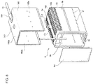
- FIG. 8 is an exploded oblique view of an air ventilation cover and a module case housing a fuel cell array according to an embodiment of the present invention.
- FIG. 9 is partial sectional view of a fuel cell unit according to an embodiment of the present invention.
- FIG. 10 is a side view of a fuel cell unit according to a working example of the present invention.
- FIGS. 11A and 11B present graphs illustrating the amount of Cr vapor emitted from caps in an embodiment of the present invention.
- FIG. 12 is a graph illustrates degradation characteristics over time of a cell when caps are used in an embodiment of the present invention.
- FIG. 1 is a partial sectional view illustrating the over-all configuration of a fuel cell unit according to an embodiment of the present invention.
- a fuel cell unit 1100 has a fuel cell and a cap 1104 provided respectively at the upper end and the lower end of the fuel cell.
- the cap 1104 may be constructed to be provided at only one end of the fuel cell unit 1100 .
- the fuel cell has a tubular construction extending in a vertical orientation (a longitudinal axial direction), and is formed in a cylindrical shape with a circular horizontal cross-section.
- a fuel electrode layer 1101 inside the tubular fuel cell has an internal flow channel 1110 that allows a fuel gas to flow through in a longitudinal axial direction.
- the tubular may be such that the contour in a horizontal cross-section is elliptical or rectangular having R at angular portions.
- the internal flow channel 1110 is not limited to one, and there may be a plurality thereof.
- the fuel cell has at least the fuel electrode layer 1101 , a solid electrolyte layer 1102 disposed on an outer side of the fuel electrode layer, and an air electrode layer 1111 disposed on an outer side of the solid electrolyte layer. There is also provided a highly conductive collector layer 1112 on an outer surface of the air electrode layer 1111 , and moreover, the air electrode layer 1111 is not provided in both end portions of the fuel cell, and a highly conductive terminal layer 1103 is formed on exposed outer surfaces of the fuel electrode layer 1101 and the solid electrolyte layer 1102 .
- the fuel electrode layer 1101 can be formed from at least one of (i) a mixture of zirconia doped with at least one species selected from Ni, Ca and Y, and a rare-earth element such as Y, Sc, or the like, (ii) a mixture of ceria doped with at least one species selected from Ni and a rare-earth element, and (iii) a mixture of lanthanum gallate doped with Ni and at least one species selected from Sr, Mg, Co, Fe, and Cu.
- the fuel electrode layer 1101 may be Ni/YSZ.
- the fuel electrode layer 1101 of this specification as described above shall be considered to include a fuel electrode catalyst layer and a supporting member.
- the fuel electrode layer 1101 may be a laminated member consisting of a conductive supporting member and a fuel electrode catalyst layer formed on the outer surface thereof, and it may also be a laminated member consisting of an insulating supporting member and a fuel electrode catalyst layer formed on the outer surface thereof. It may also have a laminate structure that includes a separately provided intermediate layer and a concentration gradient layer to enhance functionality and durability of the fuel electrode.
- the solid electrolyte layer 1102 and the air electrode layer 1111 may also have a laminate structure that includes a separately provided intermediate layer and a concentration gradient layer to enhance the functionality and durability thereof.
- the solid electrolyte layer 1102 is formed across the entire outer circumference surface of the fuel electrode layer 1101 .
- the lower end of the solid electrolyte layer 1102 terminates so as to fall short of the lower end of the fuel electrode layer 1101
- the upper end of the solid electrolyte layer 1102 terminates so as to fall short of the upper end of the fuel electrode layer 1101 .
- the solid electrolyte layer 1102 can be formed from at least one of zirconia doped with at least one rare-earth element such as Y, Sc, or the like, (ii) ceria doped with at least one species selected from the rare-earth elements, and (iii) lanthanum gallate doped with at least one species selected from Sr and Mg, for example.
- the air electrode layer 1111 is formed across the entire outer circumference surface of the solid electrolyte layer 1102 .
- the lower end of the air electrode layer 1111 terminates so as to fall short of the lower end of the solid electrolyte layer 1111
- the upper end of the air electrode layer 1111 terminates so as to fall short of the upper end of the solid electrolyte layer 1101 .
- the air electrode layer 1111 can be formed from at least one of (i) a lanthanum manganite doped with at least one species selected from Sr and Ca, (ii) a lanthanum ferrite doped with at least one species selected from Sr, Co, Ni, and Cu, (iii) a lanthanum cobaltite doped with at least one species selected from Sr, Fe, Ni, and Cu, or silver, for example.
- the fuel electrode layer 1101 functions as a ( ⁇ ) electrode for the fuel gas to flow through to the above-mentioned internal flow channel
- the air electrode layer 1111 functions as a (+) electrode that makes contact with the air (oxidant gas) supplied from the outside of the fuel cell unit 1100 (see the arrows in FIG. 1 ).
- the air electrode layer 1111 and the collector layer 1112 on the outer surface thereof extend from the center across toward the end portions in the axial orientation of the fuel cell, while terminating at a predetermined distance from an end portion of the fuel cell at both ends of the fuel cell.
- the zone in which the air electrode layer 1111 is formed functions as a power-generating element 1115 having the fuel electrode layer 1101 and the solid electrolyte layer 1102 laminated on the inner side thereof.
- the terminal layer 1103 is provided on an outer surface of the fuel electrode layer 1101 and the solid electrolyte layer 1102 in both end portions of a fuel cell in which the air electrode layer 1111 and the collector layer 1112 above it are not formed.
- the terminal layer 1103 is a thin film formed from a conductive material having silver as its primary constituent.
- the film thickness may be suitably designed for the current extraction efficiency of the fuel cell unit 1100 , with the resistance components of the conductive pathway taken into consideration.
- the terminal layer 1103 should be thin in order to reduce this effect as much as possible.
- the terminal layer 1103 is advantageously at least thinner than a glass 1105 that anchors the cap 1104 and the fuel cell, and specifically, its thickness should be at least 1 ⁇ m and no greater than 100 ⁇ m.
- the terminal layer 1103 may be pure silver, but it may be a material containing other elements, such as an alloy layer such as an AgPd film. Moreover, the terminal layer 1103 may contain elements that mutually diffuse into the solid electrolyte layer 1102 , or elements (such as Ni) that mutually diffuse into the fuel electrode layer 1101 . By containing elements that mutually diffuse into other layers, it becomes possible to enhance the bonding strength with other layers.
- the terminal layer 1103 in a site where the terminal layer 1103 is formed from a single layer, and the terminal layer 1103 connects to the fuel electrode layer 1101 (the fuel electrode connection zone 1108 shown in FIG. 2 ), it may have a laminate structure with another layer containing silver as the primary constituent and containing other elements that mutually diffuse into the fuel electrode layer 1101 , or in the site, the terminal layer 1103 may have another single layer structure having silver as the primary constituent containing elements that mutually diffuse into the fuel electrode layer 1101 .
- the collector layer 1112 and the terminal layer 1103 are separated at a predetermined distance L 0 in the longitudinal axial direction of the fuel cell, they are electrically insulated and isolated from each other.
- the separation distance is set equal to the predetermined distance L 0 in both upper end and lower end portions of the fuel cell, but the separation distance may be set different from each other in the upper and lower end portions, from the standpoint of design such as the attaching configuration of the collectors or adjusting the resistance values of the conductive pathway.
- the collector layer 1112 connected to the outer surface of the air electrode layer 1111 and the terminal layer 1103 connected to the outer surface of the fuel electrode layer 1101 form a collector structure that electrically connects to an adjacent fuel cell unit 1100 by electrically connecting to respective collector materials.
- the collector layer 1112 that is connected to the outer surface of the air electrode layer 1111 is connected via the connector member to the terminal layer that is connected to the outer surface of the fuel electrode layer of an adjacent fuel cell unit.
- the terminal layer 1103 that is connected to the outer surface of the fuel electrode layer 1101 is electrically connected to the terminal layer that is connected to the outer surface of the air electrode layer of another adjacent fuel cell unit.
- connection configuration of the fuel cell unit 1100 according to this embodiment of the present invention is not limited thereto, and the connector members may be used to connect a plurality of fuel cell units 1100 in parallel. It is also possible to structure any desired collector configuration by combining serial and parallel connections.
- the zone where the air electrode layer 1111 is provided functions as the power-generating element 1115 that generates power by an electricity-generating reaction, and both ends thereof function as an electrical current extraction section (a fuel electrode collector zone 1109 ) on the fuel electrode layer side for exposing as the outermost surface an electrical connection terminal of the fuel electrode layer 1101 that is positioned internally.
- the electrical connection terminal for the fuel cell layer 1101 and the air electrode layer 1111 on the outermost surface of the fuel cell, thus making it possible to achieve an electrical current extraction structure that does not operate via the cap 1104 .
- the fuel electrode collector zone 1109 may have its length set at 1 mm or more in the longitudinal axial direction of the fuel cell unit 1100 , and preferably at 2 mm or more. Providing a sufficient length makes it possible to secure a margin for arranging the electrical connection terminal.
- the fuel cell unit 1100 has the cap 1104 attached at both ends thereof.
- the cap 1104 has a cylindrical shape covering both ends of the tubular fuel cell. It has a hollow structure having a side surface and a top surface or a bottom surface, and having an opening at an end opposite to the top surface or the bottom surface.
- a flow-through port for the passage of fuel gas is provided on the side surface or bottom surface of the cap 1104 .
- the port functions as a fuel gas inlet port in the cap 1104 installed at the lower end of the fuel cell, and functions as an off-gas exhaust port in the cap 1104 installed at the upper end of the fuel cell.
- fuel gas containing hydrogen is supplied to the internal flow channel 1110 via the flow-through port of the cap 1104 provided at the lower end of the fuel cell unit 1100 .
- the fuel gas containing hydrogen is supplied to the fuel electrode layer 1101 via the internal flow channel 1110 , and is consumed in an electricity-generating reaction with an oxidant gas supplied to the air electrode layer 1111 from the outside of the fuel cell unit 1100 .
- Residual fuel gas that is not used in the electricity-generating reaction and off-gas such as water vapor and CO (carbon monoxide) generated by the electricity-generating reaction rise in the internal flow channel 1110 , and are discharged to the outside from the upper end of the fuel cell unit 1100 via a flow-through port of the cap 1104 disposed at the upper end of the fuel cell unit 1100 .
- the cap 1104 has a main body formed from ferritic stainless steel or austenitic stainless steel with the inner circumferential surface and the outer circumferential surface coated with a chromium oxide (Cr 2 O 3 in this embodiment), and the outer circumferential surface can further be coated with MnCo 2 O 4 in order to prevent the evaporation of chromium to the outside of the fuel cell unit 1100 .
- a chromium oxide Cr 2 O 3 in this embodiment
- stainless steel containing aluminum with an insulating film formed on the surface thereof is used in a material of the cap 1104 .
- the fuel electrode collector zone 1109 is formed to separate the cap 1104 and the air electrode layer 1111 to thereby make it possible to further suppress contamination of the air electrode layer 1111 by Cr in the cap.
- the outer diameter on the end side facing the opening is made small.
- it is designed with a shape having a small diameter (cap small diameter part) so the cap diameter reduces.
- the cap 1104 positioned at the lower end of the fuel cell unit 1100 makes it possible to ensure good anchoring and attachment to a fuel gas manifold for anchoring the fuel cell unit 1100 , as well as to equalize the flow amounts of fuel gas supplied to the internal flow channel 1110 .
- the cap 1104 positioned at the upper end of the fuel cell unit 1100 enables equalization of the flow amounts of the off-gas, so that a plurality of fuel cell units 1100 can be arranged to stabilize combustion in the combustion units for burning off-gas at the upper portion.
- FIG. 2 is a partial sectional view of the structure of an end portion of the fuel cell unit 1100 in an embodiment of the present invention.
- FIG. 2 is a drawing illustrating the lower end portion of the fuel cell unit 1100 , but the structure of the upper end portion is identical.
- a fuel cell formed from the fuel electrode layer 1101 , the solid electrolyte layer 1102 , and the air electrode layer 1111 is covered by the cap 1104 at the lower end thereof.
- the air electrode layer 1111 is not provided at the lower end of the fuel cell, and the solid electrolyte layer 1102 is exposed.
- the solid electrolyte layer 1102 is not disposed in a zone at a predetermined distance from the end portion of the fuel cell, so the fuel electrode layer 1101 is exposed.
- the terminal layer 1103 is provided to cover the outer surface of the exposed fuel electrode layer 1101 and the solid electrolyte layer 1102 .
- the terminal layer 1103 is provided on the surface of the fuel electrode layer 1101 and the solid electrolyte layer 1102 , in other words, on the side surface of the fuel cell.
- the embodiment is not limited thereto, and the terminal layer 1103 may extend to the bottom surface of the fuel cell and connect to the fuel electrode layer 1101 and the terminal layer 1103 at the bottom surface of the fuel cell.
- the fuel electrode layer 1101 and the terminal layer 1103 are connected at the bottom surface as well as the side surface of the fuel cell, it enhances the conductivity that accompanies the increased connection surface area, and contributes to enhanced adhesion.
- the fuel electrode layer 1101 is electrically connected to the terminal layer 1103 in a fuel electrode layer connection zone 1108 at an end portion of the of the exposed fuel cell, where the solid electrolyte layer 1102 is not disposed.
- the terminal layer 1103 is electrically connected to the fuel electrode layer 1101 in the vicinity of the end of the fuel cell in the fuel electrode layer connection zone 1108 , and also extends outwardly from an opening 1104 e of the cap 1104 toward the central side in the longitudinal axial direction of the fuel cell.
- the fuel cell and the cap 1104 are anchored by the glass 1105 .
- the glass 1105 is disposed in such a manner that it makes contact with a cap inner wall surface 1104 c and an outer surface of the collector 1103 , thereby anchoring both of them.
- this anchoring zone is referred to as the anchoring portion 1107 .
- the anchoring portion 1107 is disposed only on the inner wall surface of the cap inner wall surface 1104 c , but the glass 1105 may extend to the outside, beyond the opening 1104 e of the cap 1104 , and it may be arranged so as to encircle the upper portion of the cap 1104 .
- the anchoring portion 1107 in which the glass is arranged is disposed in such a manner that it does not overlap with the fuel electrode connection zone 1108 in the longitudinal axial direction of the fuel cell, but if these zones are arranged so as to overlap, that would make it possible to save space in the longitudinal axial direction of the fuel cell, and that would also contribute to reducing the size of the fuel cell unit 1100 in the longitudinal axial direction.
- the terminal layer 1103 that extends in the longitudinal axial direction toward the longitudinal center of the fuel cell facing the cap opening 1104 ee and the glass 1105 forms an electrical current extraction zone (fuel electrode collection zone) 1109 on a side surface of the fuel cell unit 1100 .
- an electrical current extraction structure extracting electrical current from the fuel electrode layer 1101 can be formed. That is to say, as illustrated in FIG. 3 , electrons (e) formed by the electricity-generating reaction migrate to the terminal layer 1103 through the fuel electrode layer connection zone 1108 , and then migrate to outside of the fuel cell unit 1100 through the electrical current extraction zone (fuel electrode collection zone) 1109 .
- the fuel gas leaks to outside of the fuel cell unit 1100 via the interior space 1106 , the fuel gas rises due to an oxidant gas the blows upward from the lower outer portion of the fuel cell unit 1100 , and hydrogen in the fuel gas passes through the collector layer 1112 , causing reduction and degradation of the air electrode layer 1111 . For that reason, it is important to use the glass 1105 to completely shield the outside of the fuel cell unit 1100 and the interior space 1106 from each other.
- a silver material such as silver wax or silver paste was embedded in the internal space of the cap, in order to connect the fuel electrode layer and the cap, but a large quantity of water vapor is formed in the reaction of oxygen and hydrogen that passed through the silver material, causing a large number of pores to be formed in the silver material, resulting in expansion of the silver material, and the formation of a fuel gas leakage pathway.
- the terminal layer 1103 that can be formed as a thin film forms a silver material used for a conductive connection and replaces the silver material of the prior art.
- the amount that passes through is minute, and even if formation of a large number of pores progresses due to the resulting water vapor, there is very little expansion, because it is a thin film. It is therefore possible to suppress leakage of fuel gas to outside of the fuel cell unit 1100 .
- the fuel cell unit 1100 employs a collector film having silver as its primary constituent, instead of the prior art collector structure employing a cap as an electricity-collection pathway, although the collector structure still employs silver, it is possible to reduce the risk of forming a harmful fuel gas leakage pathway, thus making it possible to increase the air-tight sealing of the fuel gas.
- the collector structure since it is possible to reduce the amount of costly silver that is used, it is advantageous in that it can reduce the cost of the product.
- the cap 1104 is formed from a cap substrate 1104 f formed from a cap-forming material, and an insulating film 1104 g formed so as to cover the surface of the cap substrate 1104 f.
- the cap substrate 1104 f is formed from stainless steel (SUS) containing aluminum. Because stainless steel typically contains iron (Fe) and chromium (Cr) as its primary constituents, the cap substrate itself causes Cr contamination of the air electrode. In the present invention, the stainless steel contains aluminum. For example, a ferritic stainless steel (SUS 405) may be used that contains 11.5-14.5% Cr and 0.1-0.3% Al. A commercially available stainless steel containing aluminum may be used, such as the Nisshin Steel ferritic stainless steel NCA-1 (18Cr-3Al—Ti), the Shin-Nittetsu Sumikin ferritic stainless steel NSSC-21M (18Cr-2Al-0.5Si—Ti), or the like.
- the insulating film 1104 g is provided across the entire surface of the cap substrate 1104 f , including the outer wall surface and the inner wall surface.
- the insulating film 1104 g is a dense passive state film (an oxide film formed from Al 2 O 3 ) formed by an oxidation reaction of aluminum in the cap substrate 1104 f on the surface of the cap substrate 1104 f .
- FIGS. 11A and 11B shows the results of evaluation of amounts of Cr evaporated under elevated temperatures in stainless steel containing aluminum.
- FIG. 11A and FIG. 11B show the amounts of Cr evaporated from stainless steel containing aluminum, where the horizontal axis gives the evaluation time, and the vertical axis gives the amount of evaporated Cr.
- the method of evaluating the amount of evaporated Cr involves setting up a stainless steel specimen containing aluminum in a small draft muffle furnace surrounded by an alumina cylinder, and using an x-ray fluorescence (XRF) analyzer to measure the surface of a magnesia adsorption plate installed as a top plate of the muffle furnace. Measurements were also made in cases where no specimens were set up, in order to assess the measurement environment.
- XRF x-ray fluorescence
- FIG. 11A shows cases where the temperature within the muffle furnace was set at 600° C.
- FIG. 11B shows cases where the temperature within the muffle furnace was set at 700° C. In both cases, the temperatures were set close to the electricity-generating operating temperatures of the solid oxide fuel cell.
- the black circles in the drawing represent the amounts of Cr evaporation from stainless steel containing aluminum, while the white circles represent the amounts of Cr evaporation resulting from measurements taken to assess the measurement environment when no specimens are present.
- FIG. 12 shows the results of evaluation of durability of a fuel cell unit with a cap stainless steel containing aluminum.
- FIG. 12 shows results for a fuel cell unit with a cap stainless steel containing aluminum, and for the sake of comparison, for fuel cell unit with a prior art stainless steel cap.
- FIG. 12 shows results for electrode reaction overvoltage, obtained under electricity-generating operating conditions, when measurements of alternating current impedance are taken over time (operating time) using a frequency response analyzer.
- the horizontal axis gives the operating time (unit: Hours), and the vertical axis gives the amount of change in activation overvoltage (Unit: V).
- the surface of the cap 1104 is insulated with the insulating film 1104 g , it is extremely difficult to form an electricity-collecting structure via the cap, as in the prior art.
- a collector structure that extracts electrical current directly, without passing through the cap 1104 , to the outside from the fuel electrode collector zone 1109 disposed at the end portion of the fuel cell, it is possible to realize a viable collector structure.
- evaporated Cr is prevented from adhering to the air electrode layer 1111 , thereby very significantly reducing Cr contamination in the air electrode layer, thus making it possible to achieve a highly durable fuel cell unit.
- the cap had to be made longer by a specified length in the longitudinal axial direction, in order to secure a connection zone.
- the tubular portion of the cap can be kept to a minimum length required for an air-tight sealing structure for air-tightly sealing the fuel gas. This also makes it possible to reduce the cost of the collector member.
- the second embodiment differs from the first embodiment only in having an intermediate layer 1113 disposed between the solid electrolyte layer 1102 and the terminal layer 1103 .
- the remaining structures of the two embodiments are shared, so a description of those shared portions is omitted.
- the terminal layer 1103 was provided on the outer surface of the solid electrolyte layer 1102 .
- the physical adhesion strength of a dense ceramic material such as LSGM and a conductive layer is not necessarily strong.
- the intermediate layer 1113 is disposed between the solid electrolyte layer 1102 and the terminal layer 1103 .
- the intermediate layer 1113 forms a bonding layer (peeling prevention layer) that enhances the adhesion strength thereof.
- An insulating material such as glass can be used as the intermediate layer 1113 to prevent peeling of the solid electrolyte layer 1102 and the terminal layer 1103 from each other.
- the intermediate layer 1113 can be disposed having its lower end positioned above the lower end of the solid electrolyte layer 1102 , and having its upper end positioned above the upper end of the terminal layer 1103 .
- the intermediate layer 1113 serves as a countermeasure against migration between terminal layers, but according to a third embodiment shown in FIG. 9 , a structure that differs from the second embodiment can suppress migration that occurs between the terminal layers.
- FIG. 9 illustrates the fuel cell unit 1100 according to the first embodiment to which is further provided a glass 1114 .
- the other components are shared.
- a ring-shaped glass 1114 is provided around the entire circumference of the side surface of the fuel cell unit 1100 , covering an end portion extending outward from the cap 1104 of the terminal layer 1103 on the fuel electrode layer 1101 . Accordingly, even if a difference in potential arises between the terminal layer 1103 that electrically connects to the fuel electrode layer 1101 , and the collector layer 1112 that electrically connects to the air electrode layer 1111 , the glass 1114 prevents the migration of silver, thus making it possible to prevent short-circuiting caused by migration.
- FIG. 9 illustrates a configuration in which the end portion of the terminal layer 1103 is covered by the glass 1114 , the same effect can be achieved by covering the end portion of the collector layer 1112 with the glass 1114 . It is therefore possible to prevent short-circuiting caused by migration, by covering the terminal layer end portion by the glass 1114 . Accordingly, the distance between the terminal layers can be shortened, and this, in turn, is advantageous for reducing the length of the fuel cell unit.
- FIG. 5 is a view showing the entire configuration of a solid oxide fuel cell (SOFC) housing fuel cell units according to one of the embodiments of the present invention.
- a solid oxide fuel cell device 1 SOFC
- the fuel cell module 2 has a housing 6 , and within this housing 6 there is a metallic module case 8 , and between them is interposed a thermal insulator 7 .
- an electricity generation chamber 10 which is the lower portion of the module case 8 which is a sealed space, there is installed a fuel cell array 14 in which an electricity-generating reaction occurs between the fuel gas and the oxidant gas (referred to below for convenience as “electricity-generating air” or “air”).
- the fuel cell array 14 has a plurality of serially connected fuel cells 16 .
- a combustion chamber 18 is formed as a combustion unit.
- this combustion chamber 18 residual fuel gas that was not used in the electricity-generating reaction and residual air are burned, forming an exhaust gas (i.e., a combustion gas).
- the module case 8 is surrounded by the thermal insulator 7 , which inhibits the heat within the fuel cell module 2 from escaping to the outside.
- a reformer unit 120 that reforms the fuel gas, and the combustion heat of the residual gas heats the reformer unit 120 to a temperature that makes a reforming reaction possible.
- an evaporator 140 is provided within the thermal insulator 7 .
- the evaporator 140 vaporizes water to form water vapor by implementing heat exchange between supplied water and the exhaust gas.
- a gas mixture containing the water vapor and the starting material gas (referred to below as “fuel gas”) is supplied to the reformer unit 120 inside the module case 8 .
- An auxiliary unit 4 has a purified water tank 26 for storing purified water resulting from the condensation and filtration of water contained in exhaust gas from the fuel cell module 2 , and a water flow volume control unit 28 (such as a “water pump” driven by a motor) that regulates the volume of water supplied from a storage tank.
- the auxiliary unit 4 has a gas cut-off valve 32 that cuts off fuel such as city gas supplied by a fuel supply source 30 , a desulfurizer 36 for removing sulfur from the fuel gas, a fuel flow volume control unit 38 (such as a “fuel pump” driven by a motor) that regulates the flow volume of the fuel gas, and a valve 39 that cuts off fuel gas from flowing from a fuel flow volume control unit 38 when the power is lost.
- the auxiliary unit 4 also has an electromagnetic valve 42 that cuts off air supplied from an air supply source 40 , a reforming air flow volume control unit 44 that regulates the flow volume of air and an electricity-generating air flow volume control unit 45 (with a motor-driven “air blower”), a first heater 46 that heats the reforming air supplied to the reformer unit 120 , and a second heater 48 that heats the electricity-generating air supplied to the electricity-generating chamber.
- the first heater 46 and the second heater 48 are provided to efficiently raise the temperature when starting, but they may be omitted.
- the embodiment may be configured such that within the reformer unit 120 when the device is started, first only a PDX step consisting of a partial oxidation reforming reaction (PDX) takes place, followed by an ATR step consisting of an auto-thermal reforming reaction (ATR) that combines a partial oxidation reforming reaction (PDX) and a steam reforming reaction (SR), then followed by an SR step in which only a steam reforming reaction takes place.
- the PDX step may be omitted and the process may proceed from the ATR step to the SR step.
- Both PDX step and ATR step may be omitted, so that only the SR step takes place. In cases where only the SR step tales place, the reforming air flow volume control unit 44 is not needed.
- a hot water making device 50 that is supplied with the exhaust gas is connected to the fuel cell module 2 .
- Tap water is supplied from a water supply source 24 to the hot water making device 50 .
- the tap water is heated by the heat of the exhaust gas, and supplied to a hot water storage tank of an external hot water supply device that is not pictured.
- a control box 52 is attached to the fuel cell module 2 for controlling the supply amount of fuel gas.
- an inverter 54 that serves as a power extractor (power converter) for supplying power generated by the fuel cell module to the outside is connected to the fuel cell module 2 .
- FIG. 6 is a lateral sectional view of a fuel cell module of a solid oxide fuel cell device
- FIG. 7 is a sectional view of a fuel cell module taken along the line in FIG. 6
- FIG. 8 is an exploded oblique view of a module case and a ventilation cover.
- the fuel cell module 2 has the fuel cell array 14 and the reformer unit 120 disposed within the module case 8 surrounded by the thermal insulator 7 , as well as the evaporator 140 disposed outside of the module case 8 and inside the thermal insulator 7 .
- the module case 8 is formed from a tubular body formed from a substantially rectangular top plate 8 a , a bottom plate 8 c , and a pair of opposing side plates 8 b connecting the sides of the plates 8 a and 8 c extending in the longitudinal direction (the horizontal direction in FIG. 6 ), as well as closed side plates 8 d and 8 e connecting the sides of the top and bottom plates 8 a and 8 c extending in the width-wise direction (the horizontal direction in FIG. 7 ) to close the opposing openings located at the longitudinal ends of the tubular body.
- the top plate 8 a and the side plate 8 b are covered by an air ventilation cover 160 .
- the air ventilation cover 160 has a top plate 160 a and a pair of opposing side plates 160 b .
- An open portion 167 for an exhaust pipe 171 to pass through is provided in approximately the center portion of the top plate 160 a . Separation at a specified distance is provided between the top plate 160 a and the top plate 8 a , and between the side plate 160 b and the side plate 8 b .
- air ventilation channels 161 a and 161 b are formed as oxidant gas supply channels between the outer side of the module case 8 and the heat insulator 7 , and specifically, between the top plate 8 a and the side plate 8 b of the nodule case 8 , and the top plate 160 a and the side plate 160 b of the air ventilation cover 160 (see FIG. 7 ).
- a blow-off port 8 f which has a plurality of through-holes (see FIG. 8 ).
- the electricity-generating air is supplied to inside the air ventilation channel 161 a via a flow-channel direction regulator 164 from an electricity-generating air inlet pipe 74 provided at approximately the center portion on the closed side plate 8 e side of the module case 8 (see FIG. 6 and FIG. 8 ).
- the electricity-generating air flows through the air ventilation channels 161 a and 161 b and is blown into the electricity generation chamber 10 from the blow-off port 8 f toward the fuel cell array 14 (see FIG. 7 and FIG. 8 ).
- plate fins 162 and 163 are provided to function as thermal exchange promoting members (see FIG. 7 ).
- the plate fin 162 is disposed horizontally so as to extend longitudinally and laterally between the top plate 8 a and the air ventilation cover 160 of the module case 8
- the plate fin 163 is disposed so as to extend longitudinally and vertically at a position above the fuel cell 16 .
- the electricity-generating air that flows through the air ventilation channels 161 a and 161 b undergoes thermal exchange with the exhaust gas that passes through the module case 8 (specifically, an exhaust gas channel disposed along the top plate 8 a and the side plate 8 b ) on the inner side of the plate fins 162 and 163 , particularly when passing through the plate fins 162 and 163 .
- the portion where the plate fins 162 and 163 are provided in the air ventilation channels 161 a and 161 b functions as a heat-exchanger (thermal exchange unit).
- the portion where the plate fin 162 is provided serves as the primary thermal exchange unit, while the portion where the plate fin 163 is disposed serves as a secondary thermal exchange unit.
- the evaporator 140 is affixed in such a manner as to extend horizontally above the top plate 8 a of the module case 8 .
- a portion 7 a of the insulator 7 is arranged so as to fill in the space between the evaporator 140 and the module case 8 (see FIG. 6 and FIG. 7 ).
- a fuel supply pipe 63 that supplies water and fuel starting material gas (it may contain reforming air) and an exhaust gas discharge pipe 82 (see FIG. 7 ) for discharging exhaust gas
- an exhaust pipe 171 is connected on the other end side of the evaporator 140 in the longitudinal direction.
- the exhaust pipe 171 extends downward, passing through an opening 167 formed in the top plate 160 a of the air ventilation cover 160 , and is connected to an exhaust port 111 .
- the exhaust port 111 is an opening for discharging exhaust gas formed in the combustion chamber 18 inside the module case 8 to the outside of the module case 8 , and it is formed in approximately the center of the top plate 8 a formed in a substantially rectangular shape as viewed from above the module case 8 .
- the evaporator 140 has a substantially rectangular evaporator case 141 as viewed from above.
- the evaporator case 141 is formed from an upper side case 142 and a lower side case 143 which are two low-profile bottomed rectangular tubes, and between these there is inserted an intermediate plate 144 that connects them.
- the evaporator case 141 has a two-tiered structure in the vertical orientation, with the lower tier having an exhaust channel portion 140 A through which passes the exhaust gas supplied from the exhaust pipe 171 , and with the upper tier having an evaporation portion 140 B that evaporates water supplied from the fuel supply pipe 63 to produce water vapor, and a mixing portion 140 C that mixes the water vapor produced by the evaporation portion 140 B and the starting material gas supplied from the fuel supply pipe 63 .
- the evaporation portion 140 B and the mixing portion 140 C are formed as partitioned spaces in the evaporator 140 , partitioned by means of a partitioning plate 145 formed with a plurality of communicating holes (slits) 145 a .
- the evaporation portion 140 B is filled with alumina balls (not pictured).
- the exhaust channel portion 140 A is partitioned into three spaces from the upstream side across to the downstream side of the exhaust gas by means of two partitioning plates 146 and 147 that likewise have a plurality of communicating holes.
- the second space is filled with a combustion catalyst (not pictured). That is to say, in this embodiment, the evaporator 140 includes a combustion catalyst unit in the lower tier of the vertical two-tiered structure.
- heat exchange is carried out between the water in the evaporation portion 140 B and the exhaust gas passing through the exhaust gas channel portion 140 A, with the heat of the exhaust gas causing the water in the evaporation portion 140 B to vaporize, resulting in water vapor.
- Heat exchange is also carried out between the gas mixture in the mixing portion 140 C and the exhaust gas passing through the exhaust channel portion 140 A, so the temperature of the gas mixture is raised by the heat of the exhaust gas.
- a gas mixture supply pipe 112 for supplying the mixed gas to the reformer unit 120 is connected to the mixing portion 140 C.
- the gas mixture supply pipe 112 is arranged so as to pass through the exhaust pipe 171 , with one end being connected to an opening 144 a formed in the intermediate plate 144 , while the other end is connected to a gas mixture supply port 120 a formed on a top surface of the reformer unit 120 .
- the gas mixture supply pipe 112 passes through the inside of the exhaust gas channel portion 140 A and inside the exhaust pipe 171 , and extends downward in the vertical direction down to the inside of the module case 8 , where it bends about 90° and extends horizontally along the top plate 8 a , and then bends downwards about 90° and is connected to the reformer unit 120 .
- the reformer unit 120 is disposed above the combustion chamber 18 and extends horizontally along the longitudinal direction of the module case 8 , and is anchored to the top plate 8 a .
- the reformer unit 120 has an approximately rectangular shape as viewed from above, but in its center portion there is formed a through-hole 120 b that makes the reformer unit 120 ring-shaped, and it has a casing that is formed by joining an upper side case 121 and a lower side case 122 .
- the through-hole 120 b is positioned in such a manner that, when viewed from above, it overlaps with the exhaust port 111 formed in the top plate 8 a .
- the exhaust port 111 is formed in the central position of the through hole 120 b.
- the gas mixture supply pipe 112 is connected to the gas mixture supply port 120 a disposed at the upper side case 121 , and at the other end (the closed side plate 8 d side), a fuel gas supply pipe 64 is connected to the lower side case 122 , and a hydrogen extraction pipe 65 for a hydrodesulfurizer that extends to the desulfurizer 36 is connected to the upper side case 121 .
- the reformer unit 120 is constructed such that it receives the gas mixture (i.e., the starting material gas mixed with water vapor (it may contain reforming air)) from the gas mixture supply pipe 112 , then reforms the gas mixture internally, and then discharges the gas after reforming (i.e., the fuel gas) from the fuel gas supply pipe 64 and the hydrogen extraction pipe 65 for the hydrodesulfurizer.
- the gas mixture i.e., the starting material gas mixed with water vapor (it may contain reforming air)
- the gas after reforming i.e., the fuel gas
- internal space of the reformer unit 120 is partitioned into three spaces by two partitioning plates 123 a and 123 b , it is formed from a gas mixture receiving part 120 A that receives the gas mixture from the gas mixture supply pipe 112 , a reforming part 120 B filled with a reforming catalyst (not pictured) for reforming the gas mixture, and a gas discharge part 120 C that discharges the gas that has passed through the reforming part 120 B (see FIG. 6 ).
- the reforming part 120 B is a space inserted between the partitioning plates 123 a and 123 b , and the reforming catalyst is held in this space.
- the gas mixture and the fuel gas after reforming are able to migrate by passing through a plurality of communicating holes (slits) provided in the partitioning plates 123 a and 123 b .
- the reforming catalyst may be an alumina with nickel added to its spherical surface or an alumina with ruthenium added to its spherical surface.
- the gas mixture supplied from the evaporator 140 via the gas mixture supply pipe 112 is injected through the gas mixture supply port 12 a into the gas mixture receiving part 120 A.
- This gas mixture expands inside the gas mixture receiving part 120 A and the injection velocity falls, and the gas mixture is supplied to the reforming part 120 B, passing through the partitioning plate 123 a .
- the reforming part 120 B the gas mixture that migrates at a reduced velocity is reformed to a fuel gas by a reforming catalyst.
- This fuel gas passes through the partitioning plate 123 b and is supplied to the gas discharge part 120 C.
- the fuel gas is discharged to the fuel gas supply pipe 64 and to the hydrogen extraction pipe 65 for the hydrodesulfurizer.
- the fuel gas supply pipe 64 serving as a fuel gas supply channel extends downward along the closed side plate 8 d within the module case 8 , then bends about 90° and extends horizontally to enter a manifold 66 formed below the fuel cell array 14 , and then extends horizontally again up to the vicinity of the closed plate 8 e on the opposite side.
- a plurality of fuel supply holes 64 b are formed on a lower surface of a horizontal portion 64 a of the fuel gas supply pipe 64 , and the fuel gas is supplied to the manifold 66 from the fuel supply holes 64 b .
- a lower support plate 68 having through-holes to support the fuel array 14 is attached above the manifold 66 , and the fuel gas inside the manifold 66 is supplied to inside the fuel cells 16 .
- An ignition device 83 for initiating combustion of the fuel gas and air is provided to the combustion chamber 18 .
- the reformer unit 120 is disposed so as to be at a specified distance in a horizontal direction from the side plate 8 b of the module
- FIG. 10 is a lateral sectional view illustrating a portion of a fuel cell array according to this working example.
- the fuel cell array has a plurality of arranged fuel cell units 1100 .
- the fuel cell units 1100 are each supported by a rectangular metallic lower support plate at its lower end. These lower support plates form a top surface of the manifold 66 , and through-holes are formed to allow fuel gas to flow into an internal flow channel 1110 of each fuel cell unit 1100 .
- a substantially cylindrical ceramic spacer (not pictured) is disposed between a cap 1104 on a lower end side of each fuel cell unit 1100 and the lower support plate. Insulation properties are ensured by setting the cap 1104 and the lower support plate at a distance from each other.
- a connector member 102 that electrically connects one fuel cell unit 1100 to an adjacent fuel cell unit 1100 is attached to each fuel cell unit 1100 .
- the connector member 102 is arranged so as to electrically connect a terminal layer 1103 that is electrically connected to a fuel electrode layer to a collector layer 1112 connected to an air electrode layer of the adjacent fuel cell unit 1100 .
- each connector member 102 is attached to the upper end and the lower end of each fuel cell unit, the fuel cell unit 1100 adjacent to one fuel cell unit 1100 is electrically connected by two connector members 102 (these two connector members 102 are in parallel). Accordingly, all of the fuel cell units 1100 forming the fuel cell array are electrically connected in series by each connector member 102 .
- the connector member 102 is attached to the upper end and the lower end, in order to connect the fuel cell units to each other, but this working example is not limited thereto.
- a structure attaching only to the upper end, or a structure attaching only to the lower end, or a structure attaching to the center portion of the fuel cell unit 1100 can be suitably designed, with consideration given to the electricity-generating performance, electrical current extracting performance, and durability of the fuel cell unit.
Abstract
Description
Claims (11)
Applications Claiming Priority (4)
| Application Number | Priority Date | Filing Date | Title |
|---|---|---|---|
| JP2017-022869 | 2017-02-10 | ||
| JP2017022868A JP2018129245A (en) | 2017-02-10 | 2017-02-10 | Fuel cell unit and fuel cell stack |
| JP2017-022868 | 2017-02-10 | ||
| JP2017022869A JP2018129246A (en) | 2017-02-10 | 2017-02-10 | Fuel cell unit and fuel cell stack |
Publications (2)
| Publication Number | Publication Date |
|---|---|
| US20180301715A1 US20180301715A1 (en) | 2018-10-18 |
| US10566634B2 true US10566634B2 (en) | 2020-02-18 |
Family
ID=63790324
Family Applications (1)
| Application Number | Title | Priority Date | Filing Date |
|---|---|---|---|
| US15/894,627 Active 2038-06-01 US10566634B2 (en) | 2017-02-10 | 2018-02-12 | Fuel cell unit and fuel cell array |
Country Status (1)
| Country | Link |
|---|---|
| US (1) | US10566634B2 (en) |
Citations (4)
| Publication number | Priority date | Publication date | Assignee | Title |
|---|---|---|---|---|
| US20100086824A1 (en) * | 2008-09-03 | 2010-04-08 | Michael Homel | Assemblies of hollow electrode electrochemical devices |
| US20110287339A1 (en) * | 2010-05-19 | 2011-11-24 | Jun-Won Suh | Fuel cell and method of manufacturing the same |
| US20140227623A1 (en) * | 2011-09-30 | 2014-08-14 | Toto Ltd. | Solid oxide fuel cell device |
| US10115985B2 (en) * | 2012-03-23 | 2018-10-30 | Toto Ltd. | Solid oxide fuel cell system |
-
2018
- 2018-02-12 US US15/894,627 patent/US10566634B2/en active Active
Patent Citations (4)
| Publication number | Priority date | Publication date | Assignee | Title |
|---|---|---|---|---|
| US20100086824A1 (en) * | 2008-09-03 | 2010-04-08 | Michael Homel | Assemblies of hollow electrode electrochemical devices |
| US20110287339A1 (en) * | 2010-05-19 | 2011-11-24 | Jun-Won Suh | Fuel cell and method of manufacturing the same |
| US20140227623A1 (en) * | 2011-09-30 | 2014-08-14 | Toto Ltd. | Solid oxide fuel cell device |
| US10115985B2 (en) * | 2012-03-23 | 2018-10-30 | Toto Ltd. | Solid oxide fuel cell system |
Also Published As
| Publication number | Publication date |
|---|---|
| US20180301715A1 (en) | 2018-10-18 |
Similar Documents
| Publication | Publication Date | Title |
|---|---|---|
| JP4587659B2 (en) | Manufacturing method of fuel cell stack | |
| CN107431231B (en) | Unit stacking apparatus, module, and module housing apparatus | |
| KR20060045974A (en) | Solid electrolyte fuel cell configuration | |
| JP7002900B2 (en) | Fuel cell cell stack device | |
| CN105765776B (en) | Unit stacking apparatus, module, and module housing apparatus | |
| JP5471008B2 (en) | Fuel cell | |
| JP4405196B2 (en) | Solid electrolyte fuel cell | |
| US7470480B2 (en) | Solid electrolyte fuel-cell device | |
| EP3547428A1 (en) | Electro-chemical reaction unit, electro-chemical reaction cell stack, and electro-chemical reaction unit production method | |
| US10566634B2 (en) | Fuel cell unit and fuel cell array | |
| JP2009087672A (en) | Fuel cell device and electronic device | |
| JP4475861B2 (en) | Solid oxide fuel cell unit | |
| JP6976876B2 (en) | Fuel cell cell unit | |
| JP5179153B2 (en) | Horizontally-striped fuel cell, cell stack, and fuel cell | |
| EP3407411A1 (en) | Fuel cell device | |
| US20100310966A1 (en) | Coaxial fuel cell or electrolyser module with ball interconnectors | |
| JP6277808B2 (en) | Solid oxide fuel cell stack, solid oxide fuel cell module, and solid oxide fuel cell system | |
| JP6369081B2 (en) | Solid oxide fuel cell stack, solid oxide fuel cell module, and solid oxide fuel cell system | |
| JP2018195496A (en) | Power collection structure for fuel battery cell, and manufacturing method thereof | |
| JP6013006B2 (en) | Fuel cell | |
| JP2018129246A (en) | Fuel cell unit and fuel cell stack | |
| JP6324601B1 (en) | Manifold | |
| JP2018129245A (en) | Fuel cell unit and fuel cell stack | |
| JP2018181483A (en) | Attachment structure of cap | |
| JP2018163831A (en) | Current collection structure for fuel battery cell |
Legal Events
| Date | Code | Title | Description |
|---|---|---|---|
| FEPP | Fee payment procedure |
Free format text: ENTITY STATUS SET TO UNDISCOUNTED (ORIGINAL EVENT CODE: BIG.); ENTITY STATUS OF PATENT OWNER: LARGE ENTITY |
|
| AS | Assignment |
Owner name: TOTO LTD., JAPAN Free format text: ASSIGNMENT OF ASSIGNORS INTEREST;ASSIGNORS:TAKAHASHI, YUYA;SHIRAHAMA, HIROSHI;YAMADA, MASAYUKI;AND OTHERS;SIGNING DATES FROM 20180201 TO 20180207;REEL/FRAME:044979/0592 |
|
| STPP | Information on status: patent application and granting procedure in general |
Free format text: DOCKETED NEW CASE - READY FOR EXAMINATION |
|
| STPP | Information on status: patent application and granting procedure in general |
Free format text: NON FINAL ACTION MAILED |
|
| STPP | Information on status: patent application and granting procedure in general |
Free format text: NOTICE OF ALLOWANCE MAILED -- APPLICATION RECEIVED IN OFFICE OF PUBLICATIONS |
|
| STPP | Information on status: patent application and granting procedure in general |
Free format text: PUBLICATIONS -- ISSUE FEE PAYMENT RECEIVED |
|
| AS | Assignment |
Owner name: MORIMURA SOFC TECHNOLOGY CO., LTD., JAPAN Free format text: ASSIGNMENT OF ASSIGNORS INTEREST;ASSIGNOR:TOTO LTD.;REEL/FRAME:051439/0300 Effective date: 20191211 |
|
| STCF | Information on status: patent grant |
Free format text: PATENTED CASE |
|
| MAFP | Maintenance fee payment |
Free format text: PAYMENT OF MAINTENANCE FEE, 4TH YEAR, LARGE ENTITY (ORIGINAL EVENT CODE: M1551); ENTITY STATUS OF PATENT OWNER: LARGE ENTITY Year of fee payment: 4 |