US10566162B2 - Leakage protective plug - Google Patents
Leakage protective plug Download PDFInfo
- Publication number
- US10566162B2 US10566162B2 US15/832,796 US201715832796A US10566162B2 US 10566162 B2 US10566162 B2 US 10566162B2 US 201715832796 A US201715832796 A US 201715832796A US 10566162 B2 US10566162 B2 US 10566162B2
- Authority
- US
- United States
- Prior art keywords
- pressing arm
- tripping
- reset button
- snap fitting
- leakage protective
- Prior art date
- Legal status (The legal status is an assumption and is not a legal conclusion. Google has not performed a legal analysis and makes no representation as to the accuracy of the status listed.)
- Expired - Fee Related, expires
Links
- 230000001681 protective effect Effects 0.000 title claims abstract description 34
- XEEYBQQBJWHFJM-UHFFFAOYSA-N Iron Chemical group [Fe] XEEYBQQBJWHFJM-UHFFFAOYSA-N 0.000 claims abstract description 24
- 239000002994 raw material Substances 0.000 description 2
- 230000005611 electricity Effects 0.000 description 1
Images


Classifications
-
- H—ELECTRICITY
- H01—ELECTRIC ELEMENTS
- H01H—ELECTRIC SWITCHES; RELAYS; SELECTORS; EMERGENCY PROTECTIVE DEVICES
- H01H50/00—Details of electromagnetic relays
- H01H50/16—Magnetic circuit arrangements
- H01H50/18—Movable parts of magnetic circuits, e.g. armature
- H01H50/32—Latching movable parts mechanically
- H01H50/326—Latching movable parts mechanically with manual intervention, e.g. for testing, resetting or mode selection
-
- H—ELECTRICITY
- H01—ELECTRIC ELEMENTS
- H01H—ELECTRIC SWITCHES; RELAYS; SELECTORS; EMERGENCY PROTECTIVE DEVICES
- H01H50/00—Details of electromagnetic relays
- H01H50/02—Bases; Casings; Covers
- H01H50/021—Bases; Casings; Covers structurally combining a relay and an electronic component, e.g. varistor, RC circuit
-
- H—ELECTRICITY
- H01—ELECTRIC ELEMENTS
- H01H—ELECTRIC SWITCHES; RELAYS; SELECTORS; EMERGENCY PROTECTIVE DEVICES
- H01H50/00—Details of electromagnetic relays
- H01H50/16—Magnetic circuit arrangements
- H01H50/18—Movable parts of magnetic circuits, e.g. armature
- H01H50/20—Movable parts of magnetic circuits, e.g. armature movable inside coil and substantially lengthwise with respect to axis thereof; movable coaxially with respect to coil
-
- H—ELECTRICITY
- H01—ELECTRIC ELEMENTS
- H01R—ELECTRICALLY-CONDUCTIVE CONNECTIONS; STRUCTURAL ASSOCIATIONS OF A PLURALITY OF MUTUALLY-INSULATED ELECTRICAL CONNECTING ELEMENTS; COUPLING DEVICES; CURRENT COLLECTORS
- H01R13/00—Details of coupling devices of the kinds covered by groups H01R12/70 or H01R24/00 - H01R33/00
- H01R13/66—Structural association with built-in electrical component
- H01R13/70—Structural association with built-in electrical component with built-in switch
- H01R13/713—Structural association with built-in electrical component with built-in switch the switch being a safety switch
-
- H—ELECTRICITY
- H01—ELECTRIC ELEMENTS
- H01R—ELECTRICALLY-CONDUCTIVE CONNECTIONS; STRUCTURAL ASSOCIATIONS OF A PLURALITY OF MUTUALLY-INSULATED ELECTRICAL CONNECTING ELEMENTS; COUPLING DEVICES; CURRENT COLLECTORS
- H01R24/00—Two-part coupling devices, or either of their cooperating parts, characterised by their overall structure
- H01R24/28—Coupling parts carrying pins, blades or analogous contacts and secured only to wire or cable
-
- H—ELECTRICITY
- H01—ELECTRIC ELEMENTS
- H01H—ELECTRIC SWITCHES; RELAYS; SELECTORS; EMERGENCY PROTECTIVE DEVICES
- H01H2235/00—Springs
- H01H2235/01—Spiral spring
-
- H—ELECTRICITY
- H01—ELECTRIC ELEMENTS
- H01R—ELECTRICALLY-CONDUCTIVE CONNECTIONS; STRUCTURAL ASSOCIATIONS OF A PLURALITY OF MUTUALLY-INSULATED ELECTRICAL CONNECTING ELEMENTS; COUPLING DEVICES; CURRENT COLLECTORS
- H01R2103/00—Two poles
-
- H—ELECTRICITY
- H01—ELECTRIC ELEMENTS
- H01R—ELECTRICALLY-CONDUCTIVE CONNECTIONS; STRUCTURAL ASSOCIATIONS OF A PLURALITY OF MUTUALLY-INSULATED ELECTRICAL CONNECTING ELEMENTS; COUPLING DEVICES; CURRENT COLLECTORS
- H01R24/00—Two-part coupling devices, or either of their cooperating parts, characterised by their overall structure
- H01R24/66—Two-part coupling devices, or either of their cooperating parts, characterised by their overall structure with pins, blades or analogous contacts and secured to apparatus or structure, e.g. to a wall
- H01R24/68—Two-part coupling devices, or either of their cooperating parts, characterised by their overall structure with pins, blades or analogous contacts and secured to apparatus or structure, e.g. to a wall mounted on directly pluggable apparatus
Definitions
- the present invention relates to the field of plugs, more particularly to a leakage protective plug and a tripping mechanism thereof.
- existing leakage protective plugs usually includes a tripping mechanism.
- FIG. 1 illustrates a utility model application No. 200820099570.0, titled as plug having electricity leakage protection function and previously filed by same applicant as the present invention.
- a tripping mechanism comprises a pressing bar 2 , and a pressing arm 14 and a big reset spring 11 which are sleeved on the pressing bar 2 , wherein the pressing arm 14 is upwardly and downwardly movable in relative to the pressing bar 2 , a slot 142 is arranged in the middle of the pressing arm 14 , an opening of a tripping plate 9 is positioned in the slot of the pressing arm and may be snapped into a retaining groove 21 of the pressing bar 2 so as to integrate a reset button 1 with the pressing arm 14 , wherein an iron core 8 may be moved forwardly by the tripping plate 9 under the spring force of a small spring 5 .
- a high-intensity magnetic field is generated by an electromagnetic coil 6 , which enables the tripping plate 9 to be quickly pulled by the iron core 8 and meanwhile the small reset spring 5 may be compressed by the tripping plate 9 , so that the tripping plate 9 may get away from the retaining groove 21 . Then, the pressing bar 2 is moved upwards quickly under the force of the big reset spring 11 , whereby cutting off conducting structure and thus shutting off power.
- leakage protection plug as mentioned in the above patent application is complicated that potential security risks usually exist.
- the deformation of the tripping plate which is easily caused by the movement of the iron core during tripping or other external forces, results in technical problems including poor contact of supply circuit and failure of power leakage protecting functions due to un-complete tripping.
- such leakage protection plug has a low safety coefficient.
- the present invention aims to provide a leakage protective plug and a tripping mechanism thereof which overcome the existing technical problems.
- the present invention provides a leakage protective plug, comprising a housing, and a tripping mechanism and a conducting structure which are arranged within the housing, wherein the tripping mechanism comprises a restorable reset button, a tripping bracket, and a tripping coil and a pressing arm which are arranged in the tripping bracket, wherein the reset button is sleeved in the pressing arm in which a snap fitting mechanism is positioned such that the pressing arm and the reset button may be snapped together, and the pressing arm and the reset button may be disengaged from each other under the control of the tripping coil.
- the snap fitting mechanism of the pressing arm comprises a snap fitting sliding groove arranged in the pressing arm and a snap fitting part arranged in the snap fitting sliding groove, and the reset button is upwardly and downwardly slidable in the snap fitting sliding groove and is snap fitted with the snap fitting part.
- the pressing arm may be rotated an angle under the control of the tripping coil, so as to disengage the reset button from the pressing arm.
- a slope for allowing the pressing arm to rotate an angle is provided at an end portion on the underside of the pressing arm away from the snap fitting mechanism.
- an iron core and a spring are arranged within the tripping coil
- the pressing arm is provided with a retaining sliding groove on the other side opposite to the snap fitting mechanism
- a head part of the iron core is snap fitted in the retaining sliding groove of the pressing arm and is upwardly and downwardly slidable along the inside wall thereof.
- the reset button may be restored by a reset spring arranged below the reset button.
- a pressing bar is arranged below the reset button, a reset spring is sleeved on the pressing bar, a retaining groove is arranged on the pressing bar, and the retaining groove and the snap fitting mechanism of the pressing arm may be snapped together.
- the pressing arm is provided with arms on two sides, respectively, the tripping bracket is provided with opening sliding grooves, and two arms of the pressing arm are positioned in the longitudinal opening sliding grooves.
- the housing comprises an upper housing and a lower housing which enclose a closed space in which the tripping mechanism and the conducting structure are arranged.
- the conducting structure comprises a circuit board, movable contact springs for zero connection and fire wire connection, pins for zero connection and fire wire connection, and an cutting sleeve for output lines, wherein the heads of the movable contact springs for zero connection and fire wire connection are movable contacts, the upper ends of the pins for zero connection and fire wire connection are stationary contacts, and the stationary contacts and the movable contacts correspond with each other and are contactable with each other.
- rear parts of the movable contact springs for zero connection and fire wire connection away from the movable contacts are respectively installed on two sides of the tripping bracket, and the parts with which the movable contacts are connected respectively press against the two arms of the pressing arm.
- the pins for zero connection and fire wire connection are fixed on the tripping bracket, with two pins protruding from the lower housing.
- the cutting sleeve for output lines is fixed inside the lower housing through a snap joint.
- the present invention also provide a tripping mechanism of a leakage protective plug, characterized in that: the tripping mechanism comprises a restorable reset button, a tripping bracket, and a tripping coil and a pressing arm which are arranged in the tripping bracket, wherein the reset button is sleeved in the pressing arm and a snap fitting mechanism is positioned in the pressing arm such that the pressing arm and the reset button are snapped together, and the pressing arm and the reset button are disengageable under the control of the tripping coil.
- the snap fitting mechanism of the pressing arm comprises a snap fitting sliding groove arranged in the pressing arm and a snap fitting part arranged in the snap fitting sliding groove, and the reset button is upwardly and downwardly slidable in the snap fitting sliding groove and is snap fitted with the snap fitting part.
- the pressing arm may be rotated an angle under the control of the tripping coil, so as to disengage the reset button from the pressing arm.
- a space is provided in the opening of the tripping bracket accommodating the pressing arm so as to allow the pressing arm to be rotated an angle.
- a slope for allowing the pressing arm to rotate an angle is provided at an end portion on the underside of the snap fitting mechanism.
- an iron core and a spring are arranged within the tripping coil
- the pressing arm is provided with a retaining sliding groove on the other side opposite to the snap fitting mechanism
- a head part of the iron core is snap fitted in the retaining sliding groove of the pressing arm and is upwardly and downwardly slidable along the inside wall.
- the reset button may be restored by a reset spring arranged below the reset button.
- a pressing bar is arranged below the reset button, a reset spring is sleeved on the pressing bar, the pressing bar is arranged with a retaining groove, and the retaining groove and the snap fitting mechanism of the pressing arm may be snapped together.
- the pressing arm is provided with arms on two sides, respectively, the tripping bracket is provided with opening sliding grooves, and two arms of the pressing arm are positioned in the longitudinal opening sliding grooves.
- the present invention simplify the structure of the tripping mechanism of the leakage protective plug, involves less components by providing a snap fitting mechanism in the pressing arm instead of a tripping plate and saves raw materials. It also achieves advantages including tripping function and leakage protection for plug. It has a simple and reliable tripping mechanism, and avoids technical problems including poor contact of supply circuit and failure of power leakage protecting functions due to un-complete tripping which are resulted from the deformation of the tripping plate caused by the movement of the tripping iron core and by other external forces. In addition, it extends service life for the leakage protective plug.
- FIG. 1 is an exploded view of a structure according to patent application No. 200820099570.0;
- FIG. 2 is an exploded view of a leakage protective plug according to an embodiment of the present invention
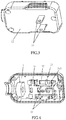
- FIG. 3 is a schematic view of an assembled leakage protective plug according to an embodiment of the present invention.
- FIG. 4 is a schematic view of the leakage protective plug as shown in FIG. 3 according to the present invention, with the upper housing being removed;
- FIG. 5 is a schematic view of a tripping mechanism of a leakage protective plug (in a conducting state) according to an embodiment of the present invention, with the tripping bracket being removed;
- FIG. 6 is a schematic view of a tripping mechanism of a leakage protective plug (in a tripping state) according to an embodiment of the present invention, with the tripping bracket being removed;
- FIG. 7 is a schematic view of a pressing arm of a leakage protective plug according to an embodiment of the present invention.
- FIG. 8 is another schematic view of the pressing arm of the leakage protective plug according to the embodiment of the present invention.
- a leakage protective plug comprises: a housing, and a tripping mechanism and a conducting structure which are arranged within the housing.
- the housing comprises an upper housing 11 and a lower housing 12 , wherein the upper housing 11 comprises a test button 111 , a test bridge 112 , and a test spring 113 , which are arranged within the upper housing 11 .
- the tripping mechanism comprises a reset button 21 , a reset spring 22 , a tripping coil 23 , a pressing arm 24 and a tripping bracket 25 , wherein a pressing bar 210 is arranged below the reset button 21 , a retaining groove 211 is arranged on the pressing bar 210 , and the tripping coil 23 comprises an iron core 231 and a spring 232 .
- the conducting structure comprises a circuit board 31 , movable contact springs 32 for zero connection and fire wire connection, pins 33 for zero connection and fire wire connection, an cutting sleeve 34 for output lines, wherein the movable contact springs 32 for zero connection and fire wire connection comprise movable contacts 321 respectively arranged at a head on one end thereof, and in this embodiment two movable contacts 321 are provided.
- the pins 33 for zero connection and fire wire connection comprise stationary contacts 331 respectively arranged at a part on an upper end thereof away from the pins, and in this embodiment two stationary contacts 331 are provided.
- the cutting sleeve 34 for output lines is fixed inside the lower housing through a snap joint 341 .
- the parts of the structure are connected in such a way that:
- the upper housing 11 and the lower housing 12 are fixedly connected by screw thread or snap fitting so as to enclose a closed space in which the tripping mechanism and the conducting structure are arranged;
- the reset button 21 is arranged in the upper housing 11 and is upwardly and downwardly movable along a vertical axis, the reset button 21 has an upper end crossing through the circuit board 31 and protruding from the upper housing 11 to form a press part; the reset spring 22 is sleeved on the pressing bar 210 of the reset button 21 , with an upper end pressing against the underside of the top of the reset button 21 and a lower end pressing against the circuit board 31 ;
- the iron core 231 and the spring 232 are arranged in a core of the tripping coil 23 , wherein the iron core 231 is movable along a horizontal axis in the core of the tripping coil 23 , the spring 232 has one end pressing against the rear part inside the core of the tripping coil 23 and the other end pressing against the head part of the iron core 231 ; furthermore, the head part of the iron core 231 is snap fitted in a retaining sliding groove 241 of the pressing arm 24 and is upwardly and downwardly slidable along the inside wall of the retaining sliding groove.
- the other side of the pressing arm 24 which is opposite to the retaining sliding groove 241 , is snap fitted with the retaining groove 211 of the reset button 21 .
- the pressing arm 24 is provided with a snap fitting mechanism 242 corresponding to the retaining groove 211 , and the snap fitting mechanism 242 of the pressing arm comprises a snap fitting sliding groove 2421 arranged in the pressing arm and a snap fitting part 2422 arranged in the snap fitting sliding groove.
- the reset button 21 is upwardly and downwardly movable in the snap fitting sliding groove 2421 and is snap fitted with the snap fitting part.
- the pressing arm 24 is upwardly and downwardly movable and is rotatable in relative to the reset button 21 .
- the pressing arm 24 is axially rotated and is displaced forwardly in relative to the reset button 21 , so as to enable the retaining groove 211 of the reset button 21 and the snap fitting mechanism 242 of the pressing arm 24 to be snapped together.
- the pressing arm 24 is further provided with arms 243 , which are respectively arranged on two sides adjacent to the retaining sliding groove 241 .
- the tripping bracket 25 is mounted on the circuit board 31 , particularly by snap joint in this embodiment.
- the tripping coil 23 is installed in the opening of the tripping bracket 25 . Opening sliding grooves are longitudinally arranged on two sides of the tripping bracket 25 .
- the pressing arm 24 is arranged in the opening of the tripping bracket 25 , at a side of the tripping coil 23 .
- Two arms 243 of the pressing arm 24 are positioned in the longitudinal opening sliding grooves, and are upwardly and downwardly moveable and are axially rotatable in a small range.
- a space is provided so as to allow the pressing arm to be rotated by a certain angle.
- a slope 244 for allowing the pressing arm to be rotated by a certain angle is provided at an end portion on the underside of the pressing arm away from the snap fitting mechanism.
- Rear parts of the movable contact springs 32 for zero connection and fire wire connection away from the movable contacts 321 are respectively installed on two sides of the tripping bracket 25 .
- the pins 33 for zero connection and fire wire connection are fixed on the tripping bracket 25 , with two pins protruding from the housing 12 .
- the pins 33 for zero connection and fire wire connection are provided with stationary contacts 331 which correspond to the movable contacts 321 and may come into contact with the movable contacts 321 so as to realize an electrical connection.
- the user may press down the press part formed on the upper end of the reset button 21 .
- the head part of the iron core 231 abuts against the retaining sliding groove 241 of the pressing arm 24 .
- the reset button 21 is pressed down, the retaining groove 211 of the reset button 21 and the snap fitting part 2422 of the snap fitting mechanism 242 are snapped together.
- the iron core 231 abuts the pressing arm 24 against the reset button 21 so that the engagement between the pressing arm 24 and the reset button 21 may be maintained.
- the pressing arm 24 is pulled by the reset button 21 and moved a short distance upwards under the force of the reset spring 22 , so that the two arms 243 on the left and right sides of the pressing arm 24 drives the movable contacts 321 positioned at the heads of the movable contact springs 32 for zero connection and fire wire connection to move upwards simultaneously, thereby enabling a contact between the movable contacts 321 and the stationary contacts 331 and establishing an electric connection.
- the tripping mechanism provided in the present embodiment omits some components such as the tripping plate of the existing plug, and meanwhile achieves leakage protection by tripping. It not only simplifies the structure and greatly saves raw materials, but also avoids technical problems including poor contact of supply circuit and failure of power leakage protecting functions due to un-complete tripping which are resulted from the deformation of the tripping plate caused by external forces.
Landscapes
- Physics & Mathematics (AREA)
- Electromagnetism (AREA)
- Breakers (AREA)
Abstract
Description
- 11. upper housing; 111. test button; 112. test bridge; 113. test spring; 12. lower housing;
- 21. reset button; 211. retaining groove; 22. reset spring; 23. tripping coil; 231. iron core; 232. spring; 24. pressing arm; 241. retaining sliding groove; 242. snap fitting mechanism; 2421. snap fitting sliding groove; 2422. snap fitting part; 243. arms; 244. slope; 25. tripping bracket;
- 31. circuit board; 32. movable contact springs for zero connection and fire wire connection; 321. movable contacts; 33. pins for zero connection and fire wire connection; 331. stationary contacts; 34. cutting sleeve for output lines; 341. snap joint.
Claims (17)
Applications Claiming Priority (6)
| Application Number | Priority Date | Filing Date | Title |
|---|---|---|---|
| CN201611110384 | 2016-12-06 | ||
| CN201621332892.6U CN206602240U (en) | 2016-12-06 | 2016-12-06 | A kind of leakage protecting plug |
| CN201611110384.8 | 2016-12-06 | ||
| CN201611110384.8A CN106953212A (en) | 2016-12-06 | 2016-12-06 | A kind of leakage protecting plug |
| CN201621332892U | 2016-12-06 | ||
| CN201621332892.6 | 2016-12-06 |
Publications (2)
| Publication Number | Publication Date |
|---|---|
| US20180158636A1 US20180158636A1 (en) | 2018-06-07 |
| US10566162B2 true US10566162B2 (en) | 2020-02-18 |
Family
ID=62244128
Family Applications (1)
| Application Number | Title | Priority Date | Filing Date |
|---|---|---|---|
| US15/832,796 Expired - Fee Related US10566162B2 (en) | 2016-12-06 | 2017-12-06 | Leakage protective plug |
Country Status (1)
| Country | Link |
|---|---|
| US (1) | US10566162B2 (en) |
Cited By (1)
| Publication number | Priority date | Publication date | Assignee | Title |
|---|---|---|---|---|
| US11757240B1 (en) * | 2021-09-08 | 2023-09-12 | Camco Manufacturing, Llc | Variable spacing electrical adapter |
Families Citing this family (7)
| Publication number | Priority date | Publication date | Assignee | Title |
|---|---|---|---|---|
| CN109357411A (en) * | 2018-11-16 | 2019-02-19 | 湖北上科电气有限公司 | A leakage protector for wall-mounted heating furnace |
| CN110491743A (en) * | 2019-09-19 | 2019-11-22 | 中山市开普电器有限公司 | A kind of breaker manual operation power cutoff mechanism |
| CN212848270U (en) * | 2020-08-14 | 2021-03-30 | 余姚市嘉荣电子电器有限公司 | A new type of maintenance leakage protector |
| CN112467483B (en) * | 2020-12-30 | 2024-11-12 | 余姚市中建电器有限公司 | Leakage protection plug |
| CN112888248A (en) * | 2021-01-11 | 2021-06-01 | 李相杰 | Network machine room high-temperature early warning power-off device |
| CN113367417B (en) * | 2021-07-05 | 2023-03-28 | 北京格雷时尚科技有限公司 | Intelligent garment with wear-resistant and electric shock-proof structural function |
| TWI799043B (en) * | 2021-12-29 | 2023-04-11 | 飛宏科技股份有限公司 | Power plug device |
Citations (4)
| Publication number | Priority date | Publication date | Assignee | Title |
|---|---|---|---|---|
| CN201230073Y (en) * | 2008-07-22 | 2009-04-29 | 佛山市顺德区信辉达电子有限公司 | Plug having electricity leakage protection function |
| US20120052702A1 (en) * | 2009-05-27 | 2012-03-01 | Zhongshan Kaper Electrical Co., Ltd. | Power plug with cable leakage protective function |
| US20130045628A1 (en) * | 2010-04-23 | 2013-02-21 | Zhongshan Kaper Electrical Co., Ltd | Electric plug |
| US20180166833A1 (en) * | 2016-12-14 | 2018-06-14 | Chengli Li | Leakage current protection device for power plug |
-
2017
- 2017-12-06 US US15/832,796 patent/US10566162B2/en not_active Expired - Fee Related
Patent Citations (4)
| Publication number | Priority date | Publication date | Assignee | Title |
|---|---|---|---|---|
| CN201230073Y (en) * | 2008-07-22 | 2009-04-29 | 佛山市顺德区信辉达电子有限公司 | Plug having electricity leakage protection function |
| US20120052702A1 (en) * | 2009-05-27 | 2012-03-01 | Zhongshan Kaper Electrical Co., Ltd. | Power plug with cable leakage protective function |
| US20130045628A1 (en) * | 2010-04-23 | 2013-02-21 | Zhongshan Kaper Electrical Co., Ltd | Electric plug |
| US20180166833A1 (en) * | 2016-12-14 | 2018-06-14 | Chengli Li | Leakage current protection device for power plug |
Cited By (1)
| Publication number | Priority date | Publication date | Assignee | Title |
|---|---|---|---|---|
| US11757240B1 (en) * | 2021-09-08 | 2023-09-12 | Camco Manufacturing, Llc | Variable spacing electrical adapter |
Also Published As
| Publication number | Publication date |
|---|---|
| US20180158636A1 (en) | 2018-06-07 |
Similar Documents
| Publication | Publication Date | Title |
|---|---|---|
| US10566162B2 (en) | Leakage protective plug | |
| US9728951B2 (en) | Leakage protection socket with reverse connection protection | |
| US10348034B1 (en) | Electrical connector assembly | |
| US12125655B2 (en) | Plug-in circuit breaker | |
| CN106025721A (en) | Three-pole power-off and leakage protection plug | |
| AU2017352603A1 (en) | Earth-leakage circuit breaker capable of being forwardly and reversely wired | |
| CN208142393U (en) | Three pole on-off leakage protecting plugs | |
| CN212848269U (en) | Maintenance type earth leakage protector | |
| CN205693086U (en) | Three extremely break leakage protecting plug | |
| CN102709125A (en) | Operating mechanism of small circuit breaker | |
| JP2020009739A (en) | Overheating destructive power disconnecting method for switch or facility using electricity | |
| CN206602240U (en) | A kind of leakage protecting plug | |
| CN104409292A (en) | Residual current circuit breaker | |
| CN109659201B (en) | Small-sized breaker for driving contact state indication | |
| CN216749757U (en) | Tripping mechanism of leakage switch | |
| CN107359089B (en) | Wall switch with overcurrent protection function | |
| CN214672452U (en) | Novel overload protection device | |
| CN212750774U (en) | Arc fault circuit breaker | |
| CN210182252U (en) | Sliding block clamping structure of moving contact system of translational isolating switch | |
| CN203377460U (en) | A new type of travel adapter | |
| CN202026133U (en) | Dual-power automatic transfer switch | |
| CN113113250A (en) | Overload protector with built-in power-off indication function | |
| WO2021093132A1 (en) | Improved structure of ground fault circuit breaker | |
| CN205723393U (en) | A kind of electromagnetic trip miniature circuit breaker | |
| CN114156134B (en) | A tripping mechanism of leakage switch |
Legal Events
| Date | Code | Title | Description |
|---|---|---|---|
| FEPP | Fee payment procedure |
Free format text: ENTITY STATUS SET TO UNDISCOUNTED (ORIGINAL EVENT CODE: BIG.); ENTITY STATUS OF PATENT OWNER: SMALL ENTITY |
|
| AS | Assignment |
Owner name: FOSHAN SHUNDE DISTRICT XINHUIDA ELECTRONICS CO., LTD., CHINA Free format text: ASSIGNMENT OF ASSIGNORS INTEREST;ASSIGNORS:LONG, HUANXIANG;GUO, QI;REEL/FRAME:044324/0805 Effective date: 20171205 Owner name: FOSHAN SHUNDE DISTRICT XINHUIDA ELECTRONICS CO., L Free format text: ASSIGNMENT OF ASSIGNORS INTEREST;ASSIGNORS:LONG, HUANXIANG;GUO, QI;REEL/FRAME:044324/0805 Effective date: 20171205 |
|
| FEPP | Fee payment procedure |
Free format text: ENTITY STATUS SET TO SMALL (ORIGINAL EVENT CODE: SMAL); ENTITY STATUS OF PATENT OWNER: SMALL ENTITY |
|
| STPP | Information on status: patent application and granting procedure in general |
Free format text: DOCKETED NEW CASE - READY FOR EXAMINATION |
|
| STPP | Information on status: patent application and granting procedure in general |
Free format text: NON FINAL ACTION MAILED |
|
| STPP | Information on status: patent application and granting procedure in general |
Free format text: RESPONSE TO NON-FINAL OFFICE ACTION ENTERED AND FORWARDED TO EXAMINER |
|
| STPP | Information on status: patent application and granting procedure in general |
Free format text: NOTICE OF ALLOWANCE MAILED -- APPLICATION RECEIVED IN OFFICE OF PUBLICATIONS |
|
| STPP | Information on status: patent application and granting procedure in general |
Free format text: PUBLICATIONS -- ISSUE FEE PAYMENT RECEIVED |
|
| STCF | Information on status: patent grant |
Free format text: PATENTED CASE |
|
| FEPP | Fee payment procedure |
Free format text: MAINTENANCE FEE REMINDER MAILED (ORIGINAL EVENT CODE: REM.); ENTITY STATUS OF PATENT OWNER: SMALL ENTITY |
|
| LAPS | Lapse for failure to pay maintenance fees |
Free format text: PATENT EXPIRED FOR FAILURE TO PAY MAINTENANCE FEES (ORIGINAL EVENT CODE: EXP.); ENTITY STATUS OF PATENT OWNER: SMALL ENTITY |
|
| STCH | Information on status: patent discontinuation |
Free format text: PATENT EXPIRED DUE TO NONPAYMENT OF MAINTENANCE FEES UNDER 37 CFR 1.362 |
|
| FP | Lapsed due to failure to pay maintenance fee |
Effective date: 20240218 |