US1056484A - Tool-holder. - Google Patents
Tool-holder. Download PDFInfo
- Publication number
- US1056484A US1056484A US68548012A US1912685480A US1056484A US 1056484 A US1056484 A US 1056484A US 68548012 A US68548012 A US 68548012A US 1912685480 A US1912685480 A US 1912685480A US 1056484 A US1056484 A US 1056484A
- Authority
- US
- United States
- Prior art keywords
- shank
- tool
- holder
- handle
- ille
- Prior art date
- Legal status (The legal status is an assumption and is not a legal conclusion. Google has not performed a legal analysis and makes no representation as to the accuracy of the status listed.)
- Expired - Lifetime
Links
- 230000037431 insertion Effects 0.000 description 4
- 238000003780 insertion Methods 0.000 description 4
- 230000002441 reversible effect Effects 0.000 description 2
- SHXWCVYOXRDMCX-UHFFFAOYSA-N 3,4-methylenedioxymethamphetamine Chemical compound CNC(C)CC1=CC=C2OCOC2=C1 SHXWCVYOXRDMCX-UHFFFAOYSA-N 0.000 description 1
- 241000125205 Anethum Species 0.000 description 1
- 241000110847 Kochia Species 0.000 description 1
- 238000010276 construction Methods 0.000 description 1
- 238000007789 sealing Methods 0.000 description 1
Images
Classifications
-
- B—PERFORMING OPERATIONS; TRANSPORTING
- B23—MACHINE TOOLS; METAL-WORKING NOT OTHERWISE PROVIDED FOR
- B23B—TURNING; BORING
- B23B31/00—Chucks; Expansion mandrels; Adaptations thereof for remote control
- B23B31/02—Chucks
- B23B31/10—Chucks characterised by the retaining or gripping devices or their immediate operating means
- B23B31/113—Retention by bayonet connection
-
- Y—GENERAL TAGGING OF NEW TECHNOLOGICAL DEVELOPMENTS; GENERAL TAGGING OF CROSS-SECTIONAL TECHNOLOGIES SPANNING OVER SEVERAL SECTIONS OF THE IPC; TECHNICAL SUBJECTS COVERED BY FORMER USPC CROSS-REFERENCE ART COLLECTIONS [XRACs] AND DIGESTS
- Y10—TECHNICAL SUBJECTS COVERED BY FORMER USPC
- Y10T—TECHNICAL SUBJECTS COVERED BY FORMER US CLASSIFICATION
- Y10T279/00—Chucks or sockets
- Y10T279/17—Socket type
- Y10T279/17888—Tang offset within socket
Definitions
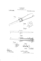
- FIG. 1 is a perspective View of my inventionu showing a. Screw driver locked in posilion for use.
- Fig. 2 is a plan View of lhe shank alone.
- Fig. 3 is a longitudinal sectional View of the holder showing the shank ⁇ ill locked position.
- Fig. 4 isn view laken about on the line 1"4 of Fig. 3, Lrho shank being shown in section.
- Fig. 5 is on enlarged detail View sllo'winjf the locking projections, 'l'orllled on the shank.
- VFig. o is all enlarged view of the end of llle forrllle. allowing more clearly the nolohos in ille edge porl'ion. oli' the opening therein.
- the oli-ler ond ol" 'the lookingflllolllllol' l2 is formed with :l lllllloll l-l lll'ojll'lillg slighlily ironl l'hoy handle l, 'lllo olllward nlol'elllenl ol' ille looking' lllelllllol' l2 is linl- ⁇ itell by means oi' a lll'ojel'lioll ll which is ⁇ adallied 'lo alllll' :lgainsl a sleeve lZl receil'ed in The ond of lllo l'wlsfa l1.
- lll ille ilse ojli' nly illl'olllioll.
- il' is l'zonlelllplal'ed lhal one end ol ille Hllallll' 7.
- locking means- :t'orrned on seid shank the opening of the hollow portion having its edges so formed as to permit of the insertion of the shank when in e predetermined position, and a locking member mounted in thehandle and normally preventing said insertion of the shank and operable to release the letter whereby said shank may be lockingly engaged with the edge of the hollow portion when turned into another predetermined position from that aforesaid.
- n handle having; a hollow body portion, e shank adapted to be received in said hollow portion, looking means formed on the shank, the opening;- of the hollow portion having its edge portion so formed es vto permit of 'the insertion of the shank only when in e predetermined position, and o locking member mounted in the handle and erren ed transversely of the opening in the bo y, said member normally preventing such insertion of the shank and operable to release the saine whereby it may 'lochingly engage with the edge of the hollow portion when partially rotated into another predetermined position from that aforesaid, said locking member then being adapted to hold the shank in tl ⁇ elest' mentioned position.l
- lnY n tool holder the combination of u handle haring n hollow bodyportion, the edge ot the opening of said hollow portion having dillerent sized notches formed therein, n reversible shank having tool elements at its opposite ends and having lugs formell in its edges for engagement in the notches aforesaid, and e spring actuated locking nieniber mounted in' seid handle normally preventing longitudinal :movement olf the shank ond adapted to permit engage-ment of the lugs aforesaid in the notches upon so' tuation of said locking member, seid loelring nieinberengaging with the tool element- .received in the handle to hold the shank in locked position.
- el. ln' a tool holder, the combination of e handle having a. hollow body portion, thel ⁇ edges of the opening of the hollow portion having different sized recesses formed there-- in', ar reversible shank having tool elcnnns at its opposite ends ond having' lugs Lroinied on its edges adopted to be received in the larger oi said recesses, a springlr :rctuzrtcd locking; member mounted in.
- the handle adjacent to the hollow portion and adopted to .non molly prevent longitudinal movement of the tool element received in thc hollow por.ltion ol the bod'ynnnd lookingA prrfmiions 'formed on the lugs aforesaid und adapted to engage in the smaller recesses upon my trnrtion oi the spring actuated locking.; inem ber and partial rotation of the shrink, seid actuated locking; member beingn adopted to hold the shtml; in locked position when released.
Landscapes
- Engineering & Computer Science (AREA)
- Mechanical Engineering (AREA)
- Details Of Spanners, Wrenches, And Screw Drivers And Accessories (AREA)
Description
geen
Ferrini onweer.
l 'ECDL-HOLDER.
Palenlced Har. 13, i913.
1q056,4 84 Specificationy of Letters Patent.
= Application filed March 22, 1912. Serial No. @$5,480. .//l v Specifically, the object olf my invention il to provide an efficient holder in which is adapted to be received il Shank comprising tool elemente, which may loe readily reversed, according to the one desired, and locked in position by partial rolaion oi said shank. the lnllldle being also provided with means whieh, when aeuated. will permit the shank o he engaged with the handle and held in locked position,
For a :lull nl'lderetanding of ille presentinvention, reference is to be had lo ille -ollowing description, and lo the accompanying drawings', in which-Figure l is a perspective View of my inventionu showing a. Screw driver locked in posilion for use. Fig. 2 is a plan View of lhe shank alone. Fig. 3 is a longitudinal sectional View of the holder showing the shank` ill locked position. Fig. 4 isn view laken about on the line 1"4 of Fig. 3, Lrho shank being shown in section. Fig. 5 is on enlarged detail View sllo'winjf the locking projections, 'l'orllled on the shank. VFig. o is all enlarged view of the end of llle forrllle. allowing more clearly the nolohos in ille edge porl'ion. oli' the opening therein.
Throughout ille following; dolailed description and on lhe several figures of ille drawings, sill'lilar parl-e1 are referred lo by like reference characters.
Referring now lo lho drawing" and spociioally describing,r the inl'elllioll. :l holder 'constructed in accordance 'l'.herewith oolnl" denoles :l shankembodying the tool elenlentsl and 8,shown ill this instance as dill'elfenlv sizellew'elv drivers. The edges of the shank are lorlned with laterally projecting lugal 9, said luge' beingr preferably iliade of equal width to the shank 7. ae ole-arly shown ill Fig. 5 of the drawing. Extending longitudinally with .respect lo the shank fl-oni oppoeile sides ol' the lng` l) are formed looking projections l0, the .eine or width of said pl'ojeelions being sllbstantially the saine as the Size of the noli-heel (3 ill the edge ol llle opening of the fel'rllle 3, while the notches 5 therein are silllilar in size to the width of the logel l) on said shank.
in the enlarged end portion of the handle Il isa llannverso lerosw 'll adjarenl lo the end ol lho hollow porlion 2 ol" ille handle` ill which is loealed a spring ael'lll led lool@ inni member l2. having al; one llld lllel'oolt an enlarged head l2 llornlall)v sealing against `J[he olller end ol llle Spil-al spring; 13 lo-oaled in lhe iilllor porlioll ol lllo revenez ll. The oli-ler ond ol" 'the lookingflllolllllol' l2 is formed with :l lllllloll l-l lll'ojll'lillg slighlily ironl l'hoy handle l, 'lllo olllward nlol'elllenl ol' ille looking' lllelllllol' l2 is linl- `itell by means oi' a lll'ojel'lioll ll which is` adallied 'lo alllll' :lgainsl a sleeve lZl receil'ed in The ond of lllo l'wlsfa l1.
lll ille ilse ojli' nly illl'olllioll. il' is l'zonlelllplal'ed lhal one end ol ille Hllallll' 7. wlli'h end cons slilllos a lool olelllenl7 in adapted lo be ineellod ill llle llollow portion 2 ol lllo handle l. ".llle enlarged llolld l2' ol lll(l looking" nlelllllol' l llorlllally lillA olliloeilo Said hollow llol'lion and ill order lo lowli lilo thank .7 ill posilioll, il is lloroosllry lo press ill'llal'dllly on lilo lllllloll ll. llloll lilol'o llllx hij;l ll lhlollo'll lllo larger lloll'll Il ill lllo llrrllle il lllllil lllo looking' llloj-fwlioll ll pasa-or; lllo odge olE lllo l'lpollingw- -l. lil' a .elilg'lll l'o- 'lalioll ol ille shank l. llle lor-hingprojo lio opter of tool element which it is desired to use. f
While l( have illustrated. 'in the drawings diilerent szed screw drivers, it will be nnderstood that the tool elements may be of different characters and other minor changes may be made in the construction and niaterial of which the `holder is composed, without departin from the spirit ot my invention, and within the scope of the claims portion, locking means- :t'orrned on seid shank, the opening of the hollow portion having its edges so formed as to permit of the insertion of the shank when in e predetermined position, and a locking member mounted in thehandle and normally preventing said insertion of the shank and operable to release the letter whereby said shank may be lockingly engaged with the edge of the hollow portion when turned into another predetermined position from that aforesaid.
2. In e tool holder, the combination of n handle having; a hollow body portion, e shank adapted to be received in said hollow portion, looking means formed on the shank, the opening;- of the hollow portion having its edge portion so formed es vto permit of 'the insertion of the shank only when in e predetermined position, and o locking member mounted in the handle and erren ed transversely of the opening in the bo y, said member normally preventing such insertion of the shank and operable to release the saine whereby it may 'lochingly engage with the edge of the hollow portion when partially rotated into another predetermined position from that aforesaid, said locking member then being adapted to hold the shank in tl\elest' mentioned position.l
. 3. lnY n tool holder, the combination of u handle haring n hollow bodyportion, the edge ot the opening of said hollow portion having dillerent sized notches formed therein, n reversible shank having tool elements at its opposite ends and having lugs formell in its edges for engagement in the notches aforesaid, and e spring actuated locking nieniber mounted in' seid handle normally preventing longitudinal :movement olf the shank ond adapted to permit engage-ment of the lugs aforesaid in the notches upon so' tuation of said locking member, seid loelring nieinberengaging with the tool element- .received in the handle to hold the shank in locked position.
el. ln' a tool holder, the combination of e handle having a. hollow body portion, thel `edges of the opening of the hollow portion having different sized recesses formed there-- in', ar reversible shank having tool elcnnns at its opposite ends ond having' lugs Lroinied on its edges adopted to be received in the larger oi said recesses, a springlr :rctuzrtcd locking; member mounted in. the handle adjacent to the hollow portion and adopted to .non molly prevent longitudinal movement of the tool element received in thc hollow por.ltion ol the bod'ynnnd lookingA prrfmiions 'formed on the lugs aforesaid und adapted to engage in the smaller recesses upon my trnrtion oi the spring actuated locking.; inem ber and partial rotation of the shrink, seid actuated locking; member beingn adopted to hold the shtml; in locked position when released.
ln testimony whereof l :rilitr my signature in presence of two witnesses.
PETER ANDERHGLEL llitnesses AN onnw Srnnnnn, 'Yeltsin Lnirvn.
Priority Applications (1)
| Application Number | Priority Date | Filing Date | Title |
|---|---|---|---|
| US68548012A US1056484A (en) | 1912-03-22 | 1912-03-22 | Tool-holder. |
Applications Claiming Priority (1)
| Application Number | Priority Date | Filing Date | Title |
|---|---|---|---|
| US68548012A US1056484A (en) | 1912-03-22 | 1912-03-22 | Tool-holder. |
Publications (1)
| Publication Number | Publication Date |
|---|---|
| US1056484A true US1056484A (en) | 1913-03-18 |
Family
ID=3124738
Family Applications (1)
| Application Number | Title | Priority Date | Filing Date |
|---|---|---|---|
| US68548012A Expired - Lifetime US1056484A (en) | 1912-03-22 | 1912-03-22 | Tool-holder. |
Country Status (1)
| Country | Link |
|---|---|
| US (1) | US1056484A (en) |
Cited By (2)
| Publication number | Priority date | Publication date | Assignee | Title |
|---|---|---|---|---|
| US2855036A (en) * | 1954-08-19 | 1958-10-07 | Orchard Brothers Inc | Joints |
| US3117386A (en) * | 1961-03-07 | 1964-01-14 | Ferwerda Ray | Tooth arrangement for earth digging apparatus |
-
1912
- 1912-03-22 US US68548012A patent/US1056484A/en not_active Expired - Lifetime
Cited By (2)
| Publication number | Priority date | Publication date | Assignee | Title |
|---|---|---|---|---|
| US2855036A (en) * | 1954-08-19 | 1958-10-07 | Orchard Brothers Inc | Joints |
| US3117386A (en) * | 1961-03-07 | 1964-01-14 | Ferwerda Ray | Tooth arrangement for earth digging apparatus |
Similar Documents
| Publication | Publication Date | Title |
|---|---|---|
| US1328430A (en) | Boring and slotting tool | |
| US994804A (en) | Hand-tool. | |
| US386263A (en) | Tool-holder and tools for the same | |
| US1054142A (en) | Spiral tool-driver. | |
| US1153575A (en) | Electric-tool handle. | |
| US958112A (en) | Boring-tool. | |
| US804602A (en) | Detachable head for boring-tools. | |
| US926845A (en) | Drill-socket. | |
| US866361A (en) | Drill attachment. | |
| US1050455A (en) | Cutter-head-knife-adjusting wrench. | |
| US1357042A (en) | Boring-tool | |
| US232369A (en) | Nut-lock | |
| US1033397A (en) | Shim. | |
| US797804A (en) | Tool-holder. | |
| US338652A (en) | weiss | |
| US1011144A (en) | Lathe tool-holder. | |
| US514308A (en) | Riley lenard davis | |
| US744335A (en) | Axle-nut lock. | |
| US188540A (en) | Improvement in convicts shackles | |
| US779289A (en) | Tool-holder. | |
| US790590A (en) | Tool-handle. | |
| US680065A (en) | Screw-driver or kindred tool. | |
| US1213888A (en) | Matcher-head. | |
| US269755A (en) | Weiss | |
| US443675A (en) | Nut-lock |