US10564255B2 - Method and device for operating a radar system of a motor vehicle - Google Patents
Method and device for operating a radar system of a motor vehicle Download PDFInfo
- Publication number
- US10564255B2 US10564255B2 US15/535,140 US201515535140A US10564255B2 US 10564255 B2 US10564255 B2 US 10564255B2 US 201515535140 A US201515535140 A US 201515535140A US 10564255 B2 US10564255 B2 US 10564255B2
- Authority
- US
- United States
- Prior art keywords
- reception signal
- time derivative
- signal
- straight line
- interference
- Prior art date
- Legal status (The legal status is an assumption and is not a legal conclusion. Google has not performed a legal analysis and makes no representation as to the accuracy of the status listed.)
- Active, expires
Links
- 238000000034 method Methods 0.000 title claims abstract description 30
- 230000004044 response Effects 0.000 claims description 25
- 230000004069 differentiation Effects 0.000 claims description 7
- 230000008030 elimination Effects 0.000 claims description 5
- 238000003379 elimination reaction Methods 0.000 claims description 5
- 230000008859 change Effects 0.000 claims description 3
- 230000005540 biological transmission Effects 0.000 description 18
- 238000009795 derivation Methods 0.000 description 16
- 238000001228 spectrum Methods 0.000 description 7
- 238000010586 diagram Methods 0.000 description 5
- 230000000694 effects Effects 0.000 description 5
- 238000001514 detection method Methods 0.000 description 3
- 230000008439 repair process Effects 0.000 description 2
- 230000003111 delayed effect Effects 0.000 description 1
- 230000002452 interceptive effect Effects 0.000 description 1
- 230000010355 oscillation Effects 0.000 description 1
- 230000008569 process Effects 0.000 description 1
- 238000005070 sampling Methods 0.000 description 1
- 238000004088 simulation Methods 0.000 description 1
Images


Classifications
-
- G—PHYSICS
- G01—MEASURING; TESTING
- G01S—RADIO DIRECTION-FINDING; RADIO NAVIGATION; DETERMINING DISTANCE OR VELOCITY BY USE OF RADIO WAVES; LOCATING OR PRESENCE-DETECTING BY USE OF THE REFLECTION OR RERADIATION OF RADIO WAVES; ANALOGOUS ARRANGEMENTS USING OTHER WAVES
- G01S7/00—Details of systems according to groups G01S13/00, G01S15/00, G01S17/00
- G01S7/02—Details of systems according to groups G01S13/00, G01S15/00, G01S17/00 of systems according to group G01S13/00
- G01S7/023—Interference mitigation, e.g. reducing or avoiding non-intentional interference with other HF-transmitters, base station transmitters for mobile communication or other radar systems, e.g. using electro-magnetic interference [EMI] reduction techniques
-
- G—PHYSICS
- G01—MEASURING; TESTING
- G01S—RADIO DIRECTION-FINDING; RADIO NAVIGATION; DETERMINING DISTANCE OR VELOCITY BY USE OF RADIO WAVES; LOCATING OR PRESENCE-DETECTING BY USE OF THE REFLECTION OR RERADIATION OF RADIO WAVES; ANALOGOUS ARRANGEMENTS USING OTHER WAVES
- G01S13/00—Systems using the reflection or reradiation of radio waves, e.g. radar systems; Analogous systems using reflection or reradiation of waves whose nature or wavelength is irrelevant or unspecified
- G01S13/88—Radar or analogous systems specially adapted for specific applications
- G01S13/93—Radar or analogous systems specially adapted for specific applications for anti-collision purposes
- G01S13/931—Radar or analogous systems specially adapted for specific applications for anti-collision purposes of land vehicles
-
- G—PHYSICS
- G01—MEASURING; TESTING
- G01S—RADIO DIRECTION-FINDING; RADIO NAVIGATION; DETERMINING DISTANCE OR VELOCITY BY USE OF RADIO WAVES; LOCATING OR PRESENCE-DETECTING BY USE OF THE REFLECTION OR RERADIATION OF RADIO WAVES; ANALOGOUS ARRANGEMENTS USING OTHER WAVES
- G01S7/00—Details of systems according to groups G01S13/00, G01S15/00, G01S17/00
- G01S7/02—Details of systems according to groups G01S13/00, G01S15/00, G01S17/00 of systems according to group G01S13/00
- G01S7/35—Details of non-pulse systems
- G01S7/352—Receivers
- G01S7/354—Extracting wanted echo-signals
-
- G01S2007/358—
-
- G—PHYSICS
- G01—MEASURING; TESTING
- G01S—RADIO DIRECTION-FINDING; RADIO NAVIGATION; DETERMINING DISTANCE OR VELOCITY BY USE OF RADIO WAVES; LOCATING OR PRESENCE-DETECTING BY USE OF THE REFLECTION OR RERADIATION OF RADIO WAVES; ANALOGOUS ARRANGEMENTS USING OTHER WAVES
- G01S7/00—Details of systems according to groups G01S13/00, G01S15/00, G01S17/00
- G01S7/02—Details of systems according to groups G01S13/00, G01S15/00, G01S17/00 of systems according to group G01S13/00
- G01S7/35—Details of non-pulse systems
- G01S7/352—Receivers
- G01S7/358—Receivers using I/Q processing
Definitions
- the present invention relates to a method and device for operating a radar system of a motor vehicle.
- US 2006/0125682 A1 describes a method, which is said to detect the start and end of an interference via jumps in the time signal or in its derivation.
- a countermeasure in the form of so-called “zero-padding” and subsequent reconstruction of the useful signal by a curve fitting or by using an average value is carried out.
- An object of the present invention is to provide an improved method for operating a radar system of a motor vehicle.
- a method for operating a radar system of a motor vehicle includes the steps of: receiving a reception signal; deriving the reception signal from time; ascertaining parameters of an interference signal from the derived reception signal; reconstructing the interference signal from the parameters; and eliminating the interference signal from the reception signal.
- a device for operating a radar system of a motor vehicle includes: a differentiation device for deriving the reception signal from time; an ascertainment device for ascertaining parameters of the derived reception signal, the parameters representing a measure for a chronological derivation of a phase response of the interference signal; a reconstruction device for reconstructing the interference signal from the parameters; and an elimination device for eliminating the interference signal from the reception signal.
- One advantageous refinement of the method provides that the parameters of the interference signal are ascertained from extreme values of the derived reception signal, a straight line being ascertained from the extreme values, which is a measure for a chronological derivation of a phase response of the interference signal. In this way, a representative image for the interference signal contained in the reception signal may be formed.
- Another advantageous refinement of the method provides that an amplitude of the interference signal is ascertained from average values of the extreme values of the reception signal. In this way, an amplitude of the interference signal can be ascertained by an estimation process.
- Another advantageous refinement of the method provides that a slope and an axis intercept of the straight line are ascertained. In this way, the chronological derivation of the phase response can be ascertained, with the aid of which the interference signal is reconstructed, in order to ascertain therefrom a useful signal from which the disruptive interference signal has been purged.
- the radar system includes an IQ mixer, a differentiation device being used for deriving the reception signal for each path of the IQ mixer, the parameters of the straight line of the chronological derivation of the phase response of the interference signal being ascertained with the aid of an ascertainment device, the portions of the reception signal derived for each path of the IQ mixer being weighted with the chronological derivation of the phase response, and the useful portions of the reception signal being ascertained for each path of the IQ mixer. In this way, it is advantageously unnecessary to determine any zero phase angle of the phase response.
- Another advantageous refinement of the method provides that the ascertainment device is provided for only one signal path of the IQ mixer. In this way, it is advantageously possible to keep the hardware outlay of the radar system to a minimum.
- Another advantageous refinement provides that an ascertainment of a zero phase angle of the phase response of the interference signals is carried out. In this way, it is also possible to carry out a reconstruction of the useful signal even in the absence of an IQ mixer.
- FIG. 1 shows a block diagram of a conventional radar system.
- FIG. 2 shows a depiction of a transmission signal of the radar system including a disruptive signal of another radar system.
- FIG. 3 shows a depiction of interference in a reception signal of the radar system.
- FIG. 4 a shows a block diagram of a device according to a first example embodiment of the present invention.
- FIG. 4 b shows a block diagram of a device according to a second example embodiment of the present invention.
- FIG. 5 shows a basic depiction of a reception signal and of its chronological derivation, according to an example embodiment of the present invention.
- FIG. 6 shows curves of a reception signal over time and of a reconstructed interference signal, according to an example embodiment of the present invention.
- FIG. 7 shows a useful signal purged from an interference signal, according to an example embodiment of the present invention.
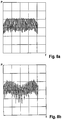
- FIG. 8 a shows a frequency spectrum before the application of the method.
- FIG. 8 b shows a frequency spectrum after the application of the method, according to an example embodiment of the present invention.
- FIG. 1 shows a block diagram of a conventional frequency modulated continuous wave radar system (FMCW).
- a generator 10 is provided, which feeds a transmission signal to a power splitter 20 .
- Half of the signal is fed from power splitter 20 to a transmission antenna 30 and half is fed to a mixer 60 .
- a reception signal reflected by targets is received by a receiving antenna 40 and is fed to a HF preamplifier 50 and subsequently to a mixer 60 .
- the transmission signal and the reception signal are multiplied by each other with the aid of mixer 60 , the result being fed to a filter 70 , for example, in the form of a low-pass, to be filtered.
- a filter 70 for example, in the form of a low-pass
- the filtered signal passes to a baseband amplifier 80 , to an analog-digital converter 90 and subsequently via an interface to a computer (not depicted).
- a baseband amplifier 80 to an analog-digital converter 90 and subsequently via an interface to a computer (not depicted).
- a computer not depicted.
- LFMCW radars linear frequency modulated continuous wave radars
- FIG. 2 shows multiple ramps f ego of the transmission signal in a time-frequency diagram, for example, as a signal having a chirp sequence modulation, which interferes in a defined range with a noise signal or interference signal s int , which is emitted, for example, by a radar system of another motor vehicle.
- a range delimited by dashes to the left and right of the transmission ramps f ego represents a reception bandwidth of the radar system, a signal reflected from a target (not depicted) including a signal curve situated in parallel to transmission ramp f ego within the reception bandwidth, the reflected signal being time delayed relative to transmission ramp f ego .
- Dashed lines to the right and left of each of transmission ramps f ego of the transmission signal illustrate an effect of filter 70 of the radar system of FIG. 1 , so that an interference effect of the transmission signal with interference signal s int only occurs in the areas illustrated by circles.
- the interference in the reception signal of the radar system has a symmetry toward the middle of the interference interval, if the frequency ramps of two RMCW radars intersect.
- a precondition of an interference effect is an at least differing slope of the modulation of the transmitting signal and of the interfering signal.
- the frequency ramp of the disruptive radar signal must lie completely within the reception bandwidth, which is indicated in FIG. 2 by two dashed lines, which is unlikely if the interference occurs at the beginning or toward the end of the useful signal. Then, the interference is not so strongly disruptive regardless, due to the windowing (for example, Henning window) of the measured data, since the values at the edge of the ramp are only weakly weighted.
- phase response ⁇ int (t) of interference signal s int over the entire duration of interference T int which can be represented mathematically as follows:
- ⁇ int (t) is phase response of the interference signal and f ing is frequency of interference signal s int , i.e., viewed over the entire interference time period T int , the phase change adds up to zero.
- Frequency response f int (t) of down-mixed interference signal or noise signal f int results from the difference between interference signal s int and the transmission signal within the reception bandwidth illustrated with circles in FIG. 2 .
- FIG. 3 shows effects of the interference on the time signal of a frequency ramp f ego of the transmission signal of the host radar. It is apparent that a minimal signal in terms of amplitude occurs on a large part of the time axis. In a range of the time axis between approximately 180 and approximately 270 (qualitative time specifications) on the other hand, an increased amplitude curve is apparent, which is caused by an interference effect of the transmission signal on a transmission signal of another radar system.
- s in (t) is the entire reception signal and s N is the useful signal, and thus forms a superposition of useful signals s use and interference signals s int .
- Phase response ⁇ int (t) of interference signal s int results from the difference between the frequency ramps of reception signal s in and interference signal s int according to the following mathematical relationship:
- Useful signals s N can be described as oscillations of constant frequency mathematically as follows: s n,i ⁇ A n,i ⁇ cos(2 ⁇ f beat,I ⁇ t+ ⁇ i ) (5)
- f beat,I is constant frequency of the nth target response after downmixing.
- FIG. 4 a illustrates in a functional manner a first specific embodiment of a device 100 for operating a radar system of a motor vehicle. It is apparent that a Q-portion and an I-portion of reception signal s in for an IQ mixer are fed to device 100 . A chronological derivation of each of the I-portion and of the Q-portion of reception signal s in is undertaken with the aid of a differentiation device 110 .
- ⁇ int (t) is chronological derivation of the phase response of the interference signal and has the form of a straight line, the parameters of which can be determined from derived reception signal s in .
- peak values or extreme values above and below a particular threshold value can be listed, since interference signal s int and its derivation have a higher amplitude than the useful signals.
- the average value thereof before the derivation supplies amplitude A int of interference signal s int .
- the extreme values in derived input signal s in can be utilized to determine the parameters of the straight line and thus to determine ⁇ int (t). In so doing, a straight line is formed by the extreme values for which there are two possible answers, which differ by factor ⁇ 1 (different slopes).
- the “false” straight line i.e., the straight line having the “false” slope results in an increase in the disruption power and can therefore be ignored as implausible. It can be detected, for example, by comparing the extreme values of reconstructed interference signal s int with the measured extreme values in reception signal s in .
- the ascertainment in this case takes place with the aid of an ascertainment device 120 .
- the ascertainment of the parameters must be carried out in each case for only one signal component I, Q, the results of the parameter ascertainment being multiplied in a step 130 by the derived signal component with the aid of a multiplier device 130 .
- the weighted result is totaled with the Q component with the aid of an elimination device 140 (summing unit), and from this useful signal s N is obtained. It is then also checked with the aid of a control device 160 whether the interference portion in reception signal s in is increased or lowered. In the event the interference portion is increased, the false straight line was used, so that the other straight line had to be used to form useful signal s N . The result, therefore, is a repaired input signal, which has been purged of interference portions.
- the approach is the same for the Q-path, a subtractor 141 being used as elimination device 141 .
- the chronological derivation of useful signals s N is very small in undisrupted areas I of reception signal s in as compared to the derivation of a reception signal s in in area II subject to interference.
- interference occurs exclusively in area II.
- the differentiated cosine signal is then weighted in such a way that the interference portion exhibits the same amplitude curve as in the sinus signal.
- the weighted signal is subtracted from the sinus signal.
- reception signal s in was purged of the interference portion or interference signal s int , so that a disruption-free useful signal s N is provided.
- there is also a loss of useful signal s N since the weighted I-component still contains parts of useful signal s N .
- a high degree of accuracy of the parameter estimation is advantageously not absolutely necessary in the case of device 100 of FIG. 4 a in order to superpose the terms in such a way that the amplitudes in the interference portions are cancelled out. Moreover, with this variant it is advantageously not necessary to determine a zero phase angle of the phase response.
- a second specific embodiment of device 100 is schematically depicted in FIG. 4 b .
- no IQ mixer is used in the radar system, interference signal s int being reproduced from the amplitude and the frequency of reception signal s in and being subtracted from reception signal s in .
- Differentiation device 110 is the same as in the specific embodiment of device 100 of FIG. 4 a , as is ascertainment device 120 .
- the zero phase angle of the phase response must also be determined in this case, for example, by ascertaining the phase relation of reception signal s in in the middle of interference duration T int (approximately in the middle of area II of FIG. 5 ).
- a chronological duration of the interference is determined either via the outermost collected peak values during the threshold value detection or via the highest occurring frequency due to the limited reception bandwidth. Since the frequency response of filter 70 has an influence on reception signal s in , previous knowledge of this can be utilized to improve an accuracy of device 100 .
- reception signal s in is represented by a solid line and the interference signal reconstructed from derived reception signal s in is represented by a dashed line.
- the measured reception signal s in and the difference between reception signal s in and reconstructed interference signals s int is represented as useful signal s N .
- the estimation of the parameters should preferably be very precise in order to carry out a meaningful reconstruction.
- FIG. 8 a shows a frequency spectrum of a radar system before the repair with the aid of the method according to the present invention. A higher noise portion in the spectrum is apparent, no close targets being present.
- FIG. 8 b shows the frequency spectrum after the repair. In the center of the spectrum, it is apparent that the noise has dropped by approximately 10 dB, and individual targets are also recognizable as lines. This is to indicate that the noise portion in the reception signal can be reduced by removing the interference portion.
- Device 100 can be advantageously implemented as a software program in the radar system. It is also conceivable, however, to implement device 100 as a software program in one or multiple control units of a motor vehicle.
- example embodiments of the present invention provide a method and a device with which a disruptive interference portion can be eliminated from a reception signal of a radar system. In this way, a detection accuracy can be increased and a signal-to-noise ratio of received signals can be improved.
Landscapes
- Engineering & Computer Science (AREA)
- Radar, Positioning & Navigation (AREA)
- Remote Sensing (AREA)
- Computer Networks & Wireless Communication (AREA)
- Physics & Mathematics (AREA)
- General Physics & Mathematics (AREA)
- Electromagnetism (AREA)
- Radar Systems Or Details Thereof (AREA)
Abstract
Description
S in(t)n =ΣS N +ΣS Int (2)
s int =A int−COS φint(t) (3)
where sint is the interference signal, Aint is amplitude of the interference signal, and φint(T) . . . is phase response of the interference signal.
where the parameters are defined as follows:
s n,i −A n,i×cos(2πf beat,I ×t+φ i) (5)
ΣA i·sin(f,t+φ i)+A int·sin(φint(t)) (9)
ΣA i·sin(f,t+φ i)+A int·sin(φint(t))−(φint(t))−1 ·A intφint(t)·sin(φint(t))=s N (10)
Claims (13)
Applications Claiming Priority (4)
| Application Number | Priority Date | Filing Date | Title |
|---|---|---|---|
| DE102014226073.6A DE102014226073A1 (en) | 2014-12-16 | 2014-12-16 | Method and device for operating a radar system of a motor vehicle |
| DE102014226073.6 | 2014-12-16 | ||
| DE102014226073 | 2014-12-16 | ||
| PCT/EP2015/074791 WO2016096207A1 (en) | 2014-12-16 | 2015-10-27 | Method and device for operating a radar system of a motor vehicle |
Publications (2)
| Publication Number | Publication Date |
|---|---|
| US20170343646A1 US20170343646A1 (en) | 2017-11-30 |
| US10564255B2 true US10564255B2 (en) | 2020-02-18 |
Family
ID=54352473
Family Applications (1)
| Application Number | Title | Priority Date | Filing Date |
|---|---|---|---|
| US15/535,140 Active 2036-09-04 US10564255B2 (en) | 2014-12-16 | 2015-10-27 | Method and device for operating a radar system of a motor vehicle |
Country Status (5)
| Country | Link |
|---|---|
| US (1) | US10564255B2 (en) |
| JP (1) | JP6533293B2 (en) |
| CN (1) | CN107003387B (en) |
| DE (1) | DE102014226073A1 (en) |
| WO (1) | WO2016096207A1 (en) |
Cited By (1)
| Publication number | Priority date | Publication date | Assignee | Title |
|---|---|---|---|---|
| US20220326345A1 (en) * | 2019-12-25 | 2022-10-13 | Huawei Technologies Co., Ltd. | Detection signal transmitting method and apparatus, and storage medium |
Families Citing this family (14)
| Publication number | Priority date | Publication date | Assignee | Title |
|---|---|---|---|---|
| DE102018200763A1 (en) * | 2018-01-18 | 2019-07-18 | Robert Bosch Gmbh | Apparatus and method for processing an input signal and radar apparatus |
| DE102018201303A1 (en) * | 2018-01-29 | 2019-08-01 | Robert Bosch Gmbh | Method and device for operating a plurality of sensors of a vehicle |
| US10482768B1 (en) * | 2018-05-08 | 2019-11-19 | Denso International America, Inc. | Vehicle function impairment detection |
| KR102733511B1 (en) * | 2018-12-04 | 2024-11-25 | 삼성전자주식회사 | Method and device to process radar data |
| JP7288330B2 (en) * | 2019-03-29 | 2023-06-07 | 古河電気工業株式会社 | Radar device and interference estimation method for radar device |
| DE102019114551B4 (en) | 2019-05-29 | 2025-10-30 | Infineon Technologies Ag | DETECTION OF INTERFERENCE-CAUSED DISTURBANCES IN FMCW RADAR SYSTEMS |
| EP3770628A1 (en) * | 2019-07-24 | 2021-01-27 | Veoneer Sweden AB | A method for radar interference mitigation |
| CN112684421A (en) * | 2019-10-17 | 2021-04-20 | 零八一电子集团有限公司 | Coherent calibration source system for linear frequency modulation continuous wave radar |
| CN112034429B (en) * | 2020-01-06 | 2022-09-20 | 中国航天科工集团八五一一研究所 | Self-adaptive digital cancellation method for eliminating interference self-excitation |
| EP4163671A4 (en) * | 2020-06-24 | 2023-08-09 | Huawei Technologies Co., Ltd. | TARGET DETECTION METHOD AND DEVICE, RADAR AND VEHICLE |
| US12130377B2 (en) * | 2021-04-29 | 2024-10-29 | Qualcomm Incorporated | Phase based search procedure for radar detection |
| WO2022269676A1 (en) * | 2021-06-21 | 2022-12-29 | 三菱電機株式会社 | Radar device and interference wave suppression device |
| US20240288532A1 (en) * | 2021-06-25 | 2024-08-29 | Mitsubishi Electric Corporation | Radar apparatus and interference wave avoidance device |
| JP7755557B2 (en) * | 2022-08-16 | 2025-10-16 | 株式会社デンソー | Automotive radar equipment |
Citations (6)
| Publication number | Priority date | Publication date | Assignee | Title |
|---|---|---|---|---|
| US20060125682A1 (en) | 2004-12-15 | 2006-06-15 | Kelly Thomas M Jr | System and method for reducing a radar interference signal |
| JP2006300550A (en) | 2005-04-15 | 2006-11-02 | Denso Corp | FMCW radar interference determination method and FMCW radar |
| JP2008180703A (en) | 2006-12-27 | 2008-08-07 | Denso It Laboratory Inc | Electronic scanning radar equipment |
| JP2009139321A (en) | 2007-12-10 | 2009-06-25 | Japan Radio Co Ltd | Radar signal processing apparatus and method |
| US20100283664A1 (en) | 2004-07-21 | 2010-11-11 | Daniel Alexander Weber | Selective-sampling receiver |
| EP2290396A2 (en) | 2009-08-31 | 2011-03-02 | Kabushiki Kaisha Toshiba | Doppler radar apparatus and method of calculating Doppler velocity |
Family Cites Families (4)
| Publication number | Priority date | Publication date | Assignee | Title |
|---|---|---|---|---|
| US7683827B2 (en) * | 2004-12-15 | 2010-03-23 | Valeo Radar Systems, Inc. | System and method for reducing the effect of a radar interference signal |
| US20130005280A1 (en) * | 2011-06-28 | 2013-01-03 | Hong Kong Applied Science and Technology Research Institute Company Limited | Method for constructing a wireless communication device to achieve motion sensing function |
| JP6080582B2 (en) * | 2013-02-07 | 2017-02-15 | 三菱電機株式会社 | Image radar device |
| CN103543126B (en) * | 2013-10-30 | 2015-12-30 | 北京航天易联科技发展有限公司 | For the signal correction compensation calculation method under the interference of gas-monitoring interference signal |
-
2014
- 2014-12-16 DE DE102014226073.6A patent/DE102014226073A1/en not_active Withdrawn
-
2015
- 2015-10-27 US US15/535,140 patent/US10564255B2/en active Active
- 2015-10-27 JP JP2017531404A patent/JP6533293B2/en active Active
- 2015-10-27 CN CN201580069050.8A patent/CN107003387B/en not_active Expired - Fee Related
- 2015-10-27 WO PCT/EP2015/074791 patent/WO2016096207A1/en not_active Ceased
Patent Citations (9)
| Publication number | Priority date | Publication date | Assignee | Title |
|---|---|---|---|---|
| US20100283664A1 (en) | 2004-07-21 | 2010-11-11 | Daniel Alexander Weber | Selective-sampling receiver |
| US20060125682A1 (en) | 2004-12-15 | 2006-06-15 | Kelly Thomas M Jr | System and method for reducing a radar interference signal |
| JP2006300550A (en) | 2005-04-15 | 2006-11-02 | Denso Corp | FMCW radar interference determination method and FMCW radar |
| JP2008180703A (en) | 2006-12-27 | 2008-08-07 | Denso It Laboratory Inc | Electronic scanning radar equipment |
| US20100019950A1 (en) | 2006-12-27 | 2010-01-28 | Denso Corporation | Electronically scanned radar system |
| JP2009139321A (en) | 2007-12-10 | 2009-06-25 | Japan Radio Co Ltd | Radar signal processing apparatus and method |
| EP2290396A2 (en) | 2009-08-31 | 2011-03-02 | Kabushiki Kaisha Toshiba | Doppler radar apparatus and method of calculating Doppler velocity |
| US20110050486A1 (en) * | 2009-08-31 | 2011-03-03 | Hiroshi Ishizawa | Doppler radar apparatus and method of calculating doppler velocity |
| US8368582B2 (en) * | 2009-08-31 | 2013-02-05 | Kabushiki Kaisha Toshiba | Doppler radar apparatus and method of calculating doppler velocity |
Non-Patent Citations (3)
| Title |
|---|
| International Search Report dated Jan. 21, 2016 of the corresponding International Application PCT/EP2015/074791 filed Oct. 27, 2015. |
| Tranlation of Description of EP2290396, Mar. 2, 2011 (Year: 2011). * |
| Translation of PCT Preliminary Report on Patentability, PCT/EP2015/074791, dated Jun. 20, 2017 (Year: 2017). * |
Cited By (2)
| Publication number | Priority date | Publication date | Assignee | Title |
|---|---|---|---|---|
| US20220326345A1 (en) * | 2019-12-25 | 2022-10-13 | Huawei Technologies Co., Ltd. | Detection signal transmitting method and apparatus, and storage medium |
| US12449505B2 (en) * | 2019-12-25 | 2025-10-21 | Shenzhen Yinwang Intelligent Technologies Co., Ltd. | Detection signal transmitting method and apparatus, and storage medium |
Also Published As
| Publication number | Publication date |
|---|---|
| CN107003387A (en) | 2017-08-01 |
| DE102014226073A1 (en) | 2016-06-16 |
| US20170343646A1 (en) | 2017-11-30 |
| WO2016096207A1 (en) | 2016-06-23 |
| CN107003387B (en) | 2021-05-14 |
| JP2017538121A (en) | 2017-12-21 |
| JP6533293B2 (en) | 2019-06-19 |
Similar Documents
| Publication | Publication Date | Title |
|---|---|---|
| US10564255B2 (en) | Method and device for operating a radar system of a motor vehicle | |
| US11016171B2 (en) | Radar sensing with phase correction | |
| KR102186191B1 (en) | Radar sensing with interference suppression | |
| JP2020067455A (en) | Fmcw radar for suppressing disturbing signal | |
| US11313943B2 (en) | Vehicle radar system arranged for reducing interference | |
| US10234541B2 (en) | FMCW radar device | |
| EP1672379B1 (en) | System and method for reducing a radar interference signal | |
| TWI504916B (en) | Signal processing method and device for frequency-modulated continuous waveform radar system | |
| JP5503961B2 (en) | Observation signal processor | |
| US9632178B2 (en) | Apparatus and method for removing noise of ultrasonic system | |
| US12072433B2 (en) | Radar interference mitigation using signal pattern matching | |
| US20120280854A1 (en) | Signal processing system and method | |
| JP6970307B2 (en) | Methods and equipment for correcting radar signals and radar equipment | |
| EP4184197A1 (en) | Automotive radar with time-frequency-antenna domain threshold interference isolation and localization fusion | |
| CN118871805A (en) | System and method for mutual interference mitigation of FMCW automotive radar | |
| JP5564244B2 (en) | Observation signal processor | |
| US20220120844A1 (en) | Method for interference suppression and method for signal restoration | |
| US10677892B2 (en) | Increasing resolution and range for I-Q linear frequency modulated radar | |
| US20230176177A1 (en) | Multi-Channel Joint Interference Mitigation | |
| JP2022108640A (en) | Chirp sequence radar system | |
| JP2022108639A (en) | Fmcw radar device |
Legal Events
| Date | Code | Title | Description |
|---|---|---|---|
| AS | Assignment |
Owner name: ROBERT BOSCH GMBH, GERMANY Free format text: ASSIGNMENT OF ASSIGNORS INTEREST;ASSIGNOR:BECHTER, JONATHAN;REEL/FRAME:043292/0420 Effective date: 20170802 |
|
| STPP | Information on status: patent application and granting procedure in general |
Free format text: DOCKETED NEW CASE - READY FOR EXAMINATION |
|
| STPP | Information on status: patent application and granting procedure in general |
Free format text: NON FINAL ACTION MAILED |
|
| STPP | Information on status: patent application and granting procedure in general |
Free format text: RESPONSE TO NON-FINAL OFFICE ACTION ENTERED AND FORWARDED TO EXAMINER |
|
| STPP | Information on status: patent application and granting procedure in general |
Free format text: NON FINAL ACTION MAILED |
|
| STPP | Information on status: patent application and granting procedure in general |
Free format text: NOTICE OF ALLOWANCE MAILED -- APPLICATION RECEIVED IN OFFICE OF PUBLICATIONS |
|
| STPP | Information on status: patent application and granting procedure in general |
Free format text: PUBLICATIONS -- ISSUE FEE PAYMENT RECEIVED |
|
| STCF | Information on status: patent grant |
Free format text: PATENTED CASE |
|
| MAFP | Maintenance fee payment |
Free format text: PAYMENT OF MAINTENANCE FEE, 4TH YEAR, LARGE ENTITY (ORIGINAL EVENT CODE: M1551); ENTITY STATUS OF PATENT OWNER: LARGE ENTITY Year of fee payment: 4 |