US10564183B2 - Scanning probe microscope and surface image correction method - Google Patents

Scanning probe microscope and surface image correction method Download PDF

Info

Publication number
US10564183B2
US10564183B2 US16/184,013 US201816184013A US10564183B2 US 10564183 B2 US10564183 B2 US 10564183B2 US 201816184013 A US201816184013 A US 201816184013A US 10564183 B2 US10564183 B2 US 10564183B2
Authority
US
United States
Prior art keywords
surface image
sample
pixels
inclination
image
Prior art date
Legal status (The legal status is an assumption and is not a legal conclusion. Google has not performed a legal analysis and makes no representation as to the accuracy of the status listed.)
Active
Application number
US16/184,013
Other versions
US20190277882A1 (en
Inventor
Masato Hirade
Current Assignee (The listed assignees may be inaccurate. Google has not performed a legal analysis and makes no representation or warranty as to the accuracy of the list.)
Shimadzu Corp
Original Assignee
Shimadzu Corp
Priority date (The priority date is an assumption and is not a legal conclusion. Google has not performed a legal analysis and makes no representation as to the accuracy of the date listed.)
Filing date
Publication date
Application filed by Shimadzu Corp filed Critical Shimadzu Corp
Assigned to SHIMADZU CORPORATION reassignment SHIMADZU CORPORATION ASSIGNMENT OF ASSIGNORS INTEREST (SEE DOCUMENT FOR DETAILS). Assignors: HIRADE, MASATO
Publication of US20190277882A1 publication Critical patent/US20190277882A1/en
Application granted granted Critical
Publication of US10564183B2 publication Critical patent/US10564183B2/en
Active legal-status Critical Current
Anticipated expiration legal-status Critical

Links

Images

Classifications

    • GPHYSICS
    • G01MEASURING; TESTING
    • G01QSCANNING-PROBE TECHNIQUES OR APPARATUS; APPLICATIONS OF SCANNING-PROBE TECHNIQUES, e.g. SCANNING PROBE MICROSCOPY [SPM]
    • G01Q30/00Auxiliary means serving to assist or improve the scanning probe techniques or apparatus, e.g. display or data processing devices
    • G01Q30/04Display or data processing devices
    • G01Q30/06Display or data processing devices for error compensation
    • GPHYSICS
    • G01MEASURING; TESTING
    • G01QSCANNING-PROBE TECHNIQUES OR APPARATUS; APPLICATIONS OF SCANNING-PROBE TECHNIQUES, e.g. SCANNING PROBE MICROSCOPY [SPM]
    • G01Q40/00Calibration, e.g. of probes
    • G06K9/3275
    • G06K9/4604
    • GPHYSICS
    • G06COMPUTING OR CALCULATING; COUNTING
    • G06VIMAGE OR VIDEO RECOGNITION OR UNDERSTANDING
    • G06V10/00Arrangements for image or video recognition or understanding
    • G06V10/20Image preprocessing
    • GPHYSICS
    • G06COMPUTING OR CALCULATING; COUNTING
    • G06VIMAGE OR VIDEO RECOGNITION OR UNDERSTANDING
    • G06V20/00Scenes; Scene-specific elements
    • G06V20/60Type of objects
    • G06V20/69Microscopic objects, e.g. biological cells or cellular parts
    • G06V20/693Acquisition
    • GPHYSICS
    • G06COMPUTING OR CALCULATING; COUNTING
    • G06VIMAGE OR VIDEO RECOGNITION OR UNDERSTANDING
    • G06V10/00Arrangements for image or video recognition or understanding
    • G06V10/20Image preprocessing
    • G06V10/24Aligning, centring, orientation detection or correction of the image
    • G06V10/247Aligning, centring, orientation detection or correction of the image by affine transforms, e.g. correction due to perspective effects; Quadrilaterals, e.g. trapezoids

Definitions

  • the present invention relates to a scanning probe microscope including a cantilever that is relatively displaced along a surface of a sample and a surface image correcting method for correcting a surface image of the sample which has been acquired by the scanning probe microscope.
  • a probe of a cantilever is caused to move along a surface of a sample such that bending of the cantilever is detected, and thereby it is possible to obtain a surface image (unevenness image) of the sample (for example, see Patent Literature 1 to be described below).
  • This type of scanning probe microscope includes an optical irradiation unit that irradiates the cantilever with a light beam and an optical detection unit that receives a reflected beam from the cantilever.
  • some scanning probe microscopes have a function of performing inclination correction on the surface image of the sample. For example, in the inclination correction, luminance of pixels (for example, pixels of one line) of the surface image of the surface, which should be horizontal at the proper posture, is extracted, and an image process is performed on the surface image of the sample by using a mean value, a median value, or the like of values of the luminance of the pixels.
  • FIG. 6 is a perspective view illustrating an example of a sample 100 , which is an observation target, and illustrates only a part of the sample 100 .
  • a surface of the sample 100 is provided with a plurality of convex portions 101 extending in a straight line, the convex portions being formed side by side in parallel, with concave portions 102 interposed therebetween.
  • the sample 100 having a surface shape as illustrated in FIG. 6 becomes an observation target in some cases.
  • inclination correction is performed on a surface image of the sample 100 , for example, it is possible to extract luminance of pixels of the surface image corresponding to the concave portions 102 along a straight line 103 parallel to the convex portion 101 and to perform inclination correction based on a mean value, a median value, or the like of the luminance of the pixels.
  • the invention is made in consideration of such circumstances described above, and an object thereof is to provide a scanning probe microscope and a surface image correcting method in which it is possible to simplify placement work of a sample.
  • a scanning probe microscope includes a cantilever, a scanning processor, and an inclination correcting processor.
  • the cantilever is relatively displaced along a surface of a sample.
  • the scanning processor performs scanning by causing the cantilever to be relatively displaced with respect to the surface of the sample in both directions of an X direction and a Y direction which intersect each other.
  • the inclination correcting processor performs an image process for correcting inclination of a surface image to a Z direction intersecting the X direction and the Y direction on the surface image of the sample which has been acquired from scanning by the scanning processor.
  • the inclination correcting processor extracts a plurality of pixels from the surface image on a straight line along a predetermined direction, corrects inclination of the surface image based on luminance of the extracted pixels, and performs an image process such that it is possible to extract the plurality of pixels along the one direction in a case where correction is performed on the surface image of the sample having a flat surface at least in the one direction intersecting the X direction and the Y direction.
  • the plurality of pixels are extracted along the one direction, and the inclination of the surface image is corrected, based on the luminance of the extracted pixels. Consequently, since luminance of pixels is not extracted along a straight line through convex portions and concave portions, a user does not need to place the sample while considering that the one direction needs to extend to be parallel to the X direction or the Y direction. Hence, it is possible to simplify placement work of the sample.
  • the inclination correcting processor may extract the plurality of pixels which are oblique with respect to the X direction and the Y direction such that the predetermined direction substantially matches the one direction.
  • the direction (predetermined direction) when the plurality of pixels are extracted from the surface image of the sample on the straight line is obliquely set with respect to the X direction and the Y direction, thereby, substantially matching the one direction.
  • the scanning probe microscope may further include an image display processor.
  • the image display processor rotates the surface image corrected by the inclination correcting processor, substantially matches the one direction to the X direction or the Y direction before rotation, and displays the surface image.
  • the surface image obtained after correcting the inclination is rotated, and thereby the one direction is caused to substantially match the X direction or the Y direction before the rotation, and the surface image is displayed. Therefore, the user more easily observes the surface image, than in a case where the surface image is displayed in a state in which the one direction is inclined with respect to the X direction and the Y direction as is.
  • the inclination correcting processor may extract the plurality of pixels after the surface image is rotated such that the one direction substantially matches the predetermined direction.
  • the surface image of the sample is rotated, and thereby the direction (predetermined direction) when the plurality of pixels are extracted from the surface image on the straight line substantially matches the one direction.
  • the inclination correcting processor may extract the plurality of pixels from one end portion to another end portion in the predetermined direction on the surface image.
  • the plurality of pixels are extracted from the one end portion to the other end portion of the surface image along the predetermined direction, and the inclination of the surface image is corrected, based on the luminance of the extracted pixels.
  • the inclination of the surface image is corrected, based on the luminance of more pixels, and thus it is possible to improve accuracy of the inclination correction.
  • a surface image correcting method for correcting a surface image of a sample which has been acquired by a scanning probe microscope that includes a cantilever that is relatively displaced along a surface of the sample and a scanning processor that performs scanning by causing the cantilever to be relatively displaced with respect to the surface of the sample in both directions of an X direction and a Y direction which intersect each other, the surface image correcting method including an inclination correcting step.
  • the inclination correcting step an image process is performed to correct inclination of the surface image to a Z direction intersecting the X direction and the Y direction on the surface image of the sample which has been acquired from scanning by the scanning processor.
  • a plurality of pixels are extracted from the surface image on a straight line along a predetermined direction, inclination of the surface image is corrected based on luminance of the extracted pixels, and an image process is performed such that it is possible to extract the plurality of pixels along the one direction in a case where correction is performed on the surface image of the sample having a flat surface at least in the one direction intersecting the X direction and the Y direction.
  • the plurality of pixels which are oblique with respect to the X direction and the Y direction may be extracted such that the predetermined direction substantially matches the one direction.
  • the plurality of pixels may be extracted after the surface image is rotated such that the one direction substantially matches the predetermined direction.
  • the plurality of pixels may be extracted from one end portion to another end portion in the predetermined direction on the surface image.
  • FIG. 1 is a conceptual diagram illustrating a configurational example of a scanning probe microscope according to an embodiment of the invention
  • FIG. 2A is a plan view illustrating a configurational example of a sample
  • FIG. 2B is a plan view illustrating a configurational example of a sample
  • FIG. 2C is a plan view illustrating a configurational example of a sample
  • FIG. 3 is a block diagram illustrating an electrical configuration of the scanning probe microscope in FIG. 1 ;
  • FIG. 4A is a view for describing a first example of inclination correction and illustrates an example of a surface image of the sample
  • FIG. 4B is a view for describing the first example of the inclination correction and illustrates an example of the surface image of the sample
  • FIG. 5 is a view for describing a second example of the inclination correction and illustrates an example of a surface image of a sample
  • FIG. 6 is a perspective view illustrating an example of a sample, which is an observation target, and illustrates only a part of the sample.
  • FIG. 1 is a conceptual diagram illustrating a configurational example of a scanning probe microscope according to an embodiment of the invention.
  • the scanning probe microscope includes a cantilever 1 , an optical irradiation unit 2 , a beam splitter 3 , a mirror 4 , an optical detection unit 5 , and a sample stage 6 .
  • the cantilever 1 is caused to move along a surface of a sample S, and thereby it is possible to obtain a surface image (unevenness image) of the sample S placed on the sample stage 6 .
  • the optical irradiation unit 2 includes a laser beam source such as a semiconductor laser and irradiates the cantilever 1 with a light beam.
  • the light beam, with which the optical irradiation unit 2 performs irradiation, is incident to the cantilever 1 through the beam splitter 3 .
  • the cantilever 1 is provided with a reflective surface 11 , and reflected beam from the reflective surface 11 is reflected from the mirror 4 and is received by the optical detection unit 5 .
  • a configuration including a photodiode such as a four-split photodiode can be employed as the optical detection unit 5 .
  • another optical member such as a collimating lens or a focus lens (both lenses not illustrated) may be provided on an optical path from the optical irradiation unit 2 to the cantilever 1 .
  • a collimating lens or a focus lens both lenses not illustrated
  • the parallel beam can be caused to focus on the focus lens and guided to a side of the cantilever 1 .
  • the collimating lens, the focus lens, and the like configure an optical system for guiding the irradiation beam from the optical irradiation unit 2 to the cantilever 1 .
  • the configuration of the optical system is not limited thereto, and a configuration may be employed, in which at least one of the optical members described above is not provided.
  • the cantilever 1 is a very small member having a length of about 150 ⁇ m and a width of about 30 to 40 ⁇ m and is provided with a probe 12 on a surface on an opposite side to the reflective surface 11 .
  • the probe 12 is caused to move along the surface of the sample S, and thereby it is possible to obtain a surface image of the sample S.
  • the reflective surface 11 of the cantilever 1 is inclined at a predetermined inclination angle ⁇ with respect to a direction orthogonal to an optical axis L of the irradiation beam from the optical irradiation unit 2 .
  • the cantilever 1 is bent, and the inclination angle ⁇ of the reflective surface 11 changes.
  • a position on the optical detection unit 5 at which the reflected beam from the reflective surface 11 is received, changes, and thereby a detection signal from the optical detection unit 5 changes. Therefore, it is possible to obtain the surface image of the sample S based on the detection signal from the optical detection unit 5 .
  • a configuration is employed, in which the cantilever 1 is displaced along the surface of the sample S; however, a configuration may be employed, in which the sample stage 6 is caused to move, and thereby the sample S is displaced with respect to the cantilever 1 . In other words, a configuration may be employed, in which the cantilever 1 is relatively displaced along the surface of the sample S.
  • FIGS. 2A to 2C are plan views illustrating a configurational example of the sample S.
  • the scanning probe microscope according to the embodiment has a function of being capable of easily performing inclination correction on the surface image of the sample S.
  • the cantilever 1 is relatively displaced along the surface of the sample S in a main-scanning direction (X direction) and a sub-scanning direction (Y direction).
  • the convex portion 21 and the concave portion 22 formed on the surface of the sample S each have a surface (top surface) having some undulations; however, a step between the convex portion 21 and the concave portion 22 has a larger difference in height than the undulation.
  • the convex portion 21 is illustrated by being hatched, and a boundary between a region (convex portion 21 ), which is hatched, and a region (concave portion 22 ), which is not hatched, is a step part between the convex portion 21 and the concave portion 22 .
  • a surface of the sample S is provided with a plurality of convex portions 21 extending in a straight line, the convex portions being formed side by side in parallel with concave portions 22 interposed therebetween.
  • luminance of pixels along a straight line 23 parallel to the Y direction is extracted.
  • values of the luminance of pixels extracted along the straight line 23 are substantially the same.
  • a surface, which should be horizontal in a proper posture is inclined, and variations in the luminance based on such inclination appear on the surface image of the sample S.
  • luminance of pixels for example, pixels along the straight line 23
  • an image process is performed on the surface image of the sample S by using a mean value, a median value, or the like of values of the luminance of the pixels. Consequently, it is possible to obtain a surface image after the inclination correction by which the variations in the luminance based on the inclination of the sample S are removed.
  • a surface of the sample S is provided with a plurality of convex portions 21 arranged in a grid pattern, with the concave portions 22 interposed therebetween.
  • the sample S is placed on the sample stage 6 such that the convex portions 21 are arranged in parallel with the X direction and the Y direction, a surface image on which the convex portions 21 and the concave portions 22 appear alternately in the X direction and the Y direction is obtained.
  • the inclination correction is performed on the surface image of the sample S as illustrated in FIG. 2B , it is possible to extract luminance of pixels not only along a straight line 24 parallel to the Y direction but also along a straight line 25 parallel to the X direction. In other words, luminance of the pixels along the straight line 24 or 25 parallel to the Y direction or the X direction, respectively, is extracted, and the inclination correction is performed on the surface image of the sample S based on the luminance of the pixels. In this manner, it is possible to obtain a surface image after the inclination correction.
  • a surface of the sample S is provided with a plurality of convex portions 21 , with the concave portions 22 interposed therebetween; however, a configuration is employed in which the convex portions 21 are not regularly formed, unlike FIG. 2A or 2B . Even in the configuration, it is possible to extract luminance of the pixels along a straight line 26 parallel to the Y direction and to perform the inclination correction on the surface image of the sample S based on the luminance of the pixels.
  • the sample S has a flat surface on which it is possible to draw the straight lines (straight lines 23 to 27 or the like) along at least one direction.
  • the flat surface may be a surface along the surface of the concave portion 22 or may be a surface along the surface of the convex portion 21 ; however, the flat surface is preferably a flat surface on which it is possible to draw a straight line from one side to another side of the surface image of the sample S.
  • the flat surface also includes a surface having some undulations smaller than the step between the convex portion 21 and the concave portion 22 , an undulation due to minute foreign matter, or the like.
  • FIG. 3 is a block diagram illustrating an electrical configuration of the scanning probe microscope in FIG. 1 .
  • the scanning probe microscope includes a control unit 7 , a storage unit 8 , a display unit 9 , and the like.
  • the scanning probe microscope further includes a cantilever moving mechanism 10 for moving the cantilever 1 in both of the X direction and the Y direction.
  • control unit 7 is configured to have a central processing unit (CPU).
  • the CPU executes a program, thereby, functioning as a scanning processor 71 , an image acquiring processor 72 , an inclination correcting processor 73 , an image display processor 74 , and the like.
  • the storage unit 8 is configured of a random access memory (RAM), a hard disk, or the like.
  • the display unit 9 is configured of a liquid crystal display or the like, and is capable of displaying various types of images such as the surface image of the sample S.
  • the scanning processor 71 controls the cantilever moving mechanism 10 , thereby relatively displacing the cantilever 1 with respect to the surface of the sample S. Consequently, it is possible to cause the cantilever 1 to scan the surface of the sample S in the main-scanning direction (X direction) and the sub-scanning direction (Y direction).
  • the image acquiring processor 72 acquires the surface image of the sample S based on a detection signal from the optical detection unit 5 while the scanning processor 71 causes the cantilever 1 to perform scanning.
  • the luminance of the pixels of the surface image of the sample S has values obtained depending on strength of the detection signal from the optical detection unit 5 .
  • the surface image of the sample S, which has been acquired by the image acquiring processor 72 is stored in the storage unit 8 .
  • the inclination correcting processor 73 performs an image process for correcting inclination of the surface image to a Z direction intersecting the X direction and the Y direction on the surface image of the sample S. Specifically, the inclination correcting processor 73 extracts the plurality of pixels from the surface image of the sample S on a straight line along a predetermined direction and corrects the inclination of the surface image in the Z direction based on the luminance of the extracted pixels.
  • luminance differences between the pixels on the straight line are calculated with respect to the reference value.
  • the luminance differences between the pixels on the straight line are computed to be added to or subtracted from luminance values of pixels aligned in a direction orthogonal to the straight line, and thereby it is possible to perform the inclination correction of the pixels of the entire surface image of the sample S.
  • the X direction and the Y direction are orthogonal to each other in a horizontal plane
  • the Z direction is a vertical direction (refer to FIG. 1 ); however, the directions are not limited thereto, as long as the X direction, the Y direction, and the Z direction intersect each other.
  • the image display processor 74 displays, on the display unit 9 , the surface image of the sample S after the inclination correction is performed by the inclination correcting processor 73 .
  • the image display processor 74 may be capable of displaying the surface image on the display unit 9 after an image process such as a rotation process for rotating the surface image of the sample S other than the inclination correction is performed on the surface image.
  • FIGS. 4A and 4B are views for describing a first example of the inclination correction and illustrate an example of the surface image of the sample S.
  • the sample S illustrated in FIG. 2A is placed on the sample stage 6 such that the convex portions 21 extend in one direction (P direction) intersecting the X direction and the Y direction, and the surface image (refer to FIG. 4A ) of the sample S, which is acquired through scanning performed by the cantilever 1 in this state, is described.
  • the inclination correcting processor 73 is configured to extract a plurality of pixels which are oblique with respect to the X direction and the Y direction such that a direction (predetermined direction) of a straight line 28 when a plurality of pixels are extracted on one straight line substantially matches the P direction.
  • a process for extracting an edge (step part between the edge the convex portion 21 and the concave portion 22 ) from the surface image of the sample S is performed, and an inclination angle of the P direction with respect to the X direction or the Y direction can be determined by calculating an inclination angle of the edge.
  • the process is not limited to such a configuration and may employ a configuration in which a user manually inputs the inclination angle, for example.
  • the plurality of pixels are extracted along the P direction, and the inclination of the surface image is corrected, based on the luminance of the extracted pixels (inclination correcting step). Consequently, since luminance of pixels is not extracted along a straight line through the convex portions 21 and the concave portions 22 , a user does not need to place the sample S while considering that the P direction needs to extend to be parallel to the X direction or the Y direction. Hence, it is possible to simplify placement work of the sample S.
  • the direction (predetermined direction) when the plurality of pixels are extracted from the surface image of the sample S on the straight line is obliquely set with respect to the X direction and the Y direction, thereby, substantially matching the P direction.
  • the direction in which the sample S is placed it is possible to automatically extract the plurality of pixels along the predetermined direction that substantially matches the P direction and to correct inclination of the surface image based on the luminance of the extracted pixels.
  • the surface image after the correction by the inclination correcting processor 73 may be rotated by the image display processor 74 , and then may be displayed on the display unit 9 .
  • the surface image is rotated such that the P direction substantially matches the X direction or the Y direction (Y direction in the example in FIG. 4B ).
  • a rotation angle of the surface image in this case can be determined, based on an inclination angle of the P direction with respect to the X direction or the Y direction, which is calculated as described above.
  • the surface image obtained after correcting the inclination is rotated, and thereby the P direction is caused to substantially match the X direction or the Y direction before the rotation, and the surface image (surface image illustrated in FIG. 4B ) is displayed. Therefore, the user more easily observes the surface image, than in a case where the surface image (surface image illustrated in FIG. 4A ) is displayed in a state in which the P direction is inclined with respect to the X direction and the Y direction as is.
  • the plurality of pixels are extracted from one end portion 281 to another end portion 282 of the surface image of the sample S in the predetermined direction (direction of the straight line 28 ), and the inclination of the surface image is corrected, based on the luminance of the extracted pixels.
  • the inclination of the surface image is corrected, based on the luminance of more pixels, and thus it is possible to improve accuracy of the inclination correction.
  • the example is not limited to the configuration in which the plurality of pixels are extracted from the one end portion 281 to the other end portion 282 along the straight line 28 , and a configuration may be employed, in which only a part of pixels on the straight line 28 are extracted, and the inclination of the surface image is corrected, based on the luminance of the extracted pixels.
  • FIG. 5 is a view for describing a second example of the inclination correction and illustrates an example of a surface image of the sample S.
  • the sample S illustrated in FIG. 2A is placed on the sample stage 6 such that the convex portions 21 extend in the one direction (P direction) intersecting the X direction and the Y direction, and a state of rotating the surface image (refer to FIG. 4A ) of the sample S, which is acquired through the scanning performed by the cantilever 1 in this state (refer to FIG. 5 ), is described.
  • the direction (predetermined direction) of the straight line 28 when the plurality of pixels are extracted on the one straight line is set to either the X direction or the Y direction before the rotation (in this example, the Y direction) in advance.
  • a configuration is employed in which, after the P direction is caused to substantially match the predetermined direction (direction of the straight line 28 ) by rotating the surface image of the sample S, the plurality of pixels are extracted.
  • the plurality of pixels are extracted along the P direction, and the inclination of the surface image is corrected, based on the luminance of the extracted pixels (inclination correcting step). Consequently, since luminance of pixels is not extracted along a straight line through the convex portions 21 and the concave portions 22 , a user does not need to place the sample S while considering that the P direction needs to extend to be parallel to the X direction or the Y direction. Hence, it is possible to simplify the placement work of the sample S.
  • the surface image of the sample S is rotated, and thereby the direction (predetermined direction) when the plurality of pixels are extracted from the surface image on the straight line substantially matches the P direction.
  • the direction predetermined direction
  • the plurality of pixels are extracted from the one end portion 281 to the other end portion 282 of the surface image of the sample S in the predetermined direction (direction of the straight line 28 ), and the inclination of the surface image is corrected, based on the luminance of the extracted pixels.
  • the inclination of the surface image is corrected, based on the luminance of more pixels, and thus it is possible to improve accuracy of the inclination correction.
  • the example is not limited to the configuration in which the plurality of pixels are extracted from the one end portion 281 to the other end portion 282 along the straight line 28 , and a configuration may be employed, in which only a part of pixels on the straight line 28 are extracted, and the inclination of the surface image is corrected, based on the luminance of the extracted pixels.
  • a program for causing a computer to execute a surface image correcting method according to the invention may be provided.
  • a configuration may be employed, in which the program is provided in a state of being stored in a storage medium, or a configuration may be employed, in which the program is provided via wired communication or wireless communication.

Landscapes

  • Engineering & Computer Science (AREA)
  • Physics & Mathematics (AREA)
  • General Physics & Mathematics (AREA)
  • Health & Medical Sciences (AREA)
  • General Health & Medical Sciences (AREA)
  • Theoretical Computer Science (AREA)
  • Multimedia (AREA)
  • Nuclear Medicine, Radiotherapy & Molecular Imaging (AREA)
  • Radiology & Medical Imaging (AREA)
  • Molecular Biology (AREA)
  • Biomedical Technology (AREA)
  • Life Sciences & Earth Sciences (AREA)
  • Length Measuring Devices With Unspecified Measuring Means (AREA)

Abstract

An inclination correcting processor performs an image process for correcting inclination of a surface image to a Z direction intersecting an X direction and a Y direction on the surface image of a sample which has been acquired from scanning by a scanning processor. The inclination correcting processor extracts a plurality of pixels from the surface image on a straight line along a predetermined direction and corrects inclination of the surface image based on luminance of the extracted pixels. In a case where correction is performed on the surface image of the sample having a flat surface at least in the one direction (P direction) intersecting the X direction and the Y direction, the inclination correcting processor performs the image process such that the predetermined direction (a direction of a straight line 28) substantially matches the one direction (P direction).

Description

FIELD
The present invention relates to a scanning probe microscope including a cantilever that is relatively displaced along a surface of a sample and a surface image correcting method for correcting a surface image of the sample which has been acquired by the scanning probe microscope.
BACKGROUND
For example, in an optical lever type of scanning probe microscope, a probe of a cantilever is caused to move along a surface of a sample such that bending of the cantilever is detected, and thereby it is possible to obtain a surface image (unevenness image) of the sample (for example, see Patent Literature 1 to be described below). This type of scanning probe microscope includes an optical irradiation unit that irradiates the cantilever with a light beam and an optical detection unit that receives a reflected beam from the cantilever.
In a case where the sample is not horizontally placed, a surface, which should be horizontal in a proper posture, is inclined, and variations in luminance based on such inclination appear on the surface image of the sample. Therefore, a problem arises in that an accurate surface image is not obtained. In this respect, some scanning probe microscopes have a function of performing inclination correction on the surface image of the sample. For example, in the inclination correction, luminance of pixels (for example, pixels of one line) of the surface image of the surface, which should be horizontal at the proper posture, is extracted, and an image process is performed on the surface image of the sample by using a mean value, a median value, or the like of values of the luminance of the pixels.
FIG. 6 is a perspective view illustrating an example of a sample 100, which is an observation target, and illustrates only a part of the sample 100. A surface of the sample 100 is provided with a plurality of convex portions 101 extending in a straight line, the convex portions being formed side by side in parallel, with concave portions 102 interposed therebetween. For example, in a case where a semiconductor component is observed as the sample, the sample 100 having a surface shape as illustrated in FIG. 6 becomes an observation target in some cases.
In a case where inclination correction is performed on a surface image of the sample 100, for example, it is possible to extract luminance of pixels of the surface image corresponding to the concave portions 102 along a straight line 103 parallel to the convex portion 101 and to perform inclination correction based on a mean value, a median value, or the like of the luminance of the pixels.
  • [Patent Literature 1] JP-A-2014-211372
SUMMARY
As described above, in a case where the luminance of the pixels is extracted and inclination correction is performed, it is not possible to extract luminance of pixels along a straight line parallel to either direction of a main-scanning direction (X direction) or a sub-scanning direction (Y direction), in the related art. As illustrated in FIG. 6, when the straight line 103 is parallel to the Y direction, it is possible to extract luminance of pixels along the straight line 103. However, in a case where the sample 100 is placed in a direction in which the convex portions 101 are inclined in the X direction and the Y direction, it is not possible to extract luminance of pixels along the straight line 103.
In this case, luminance of pixels along a straight line through the convex portions 101 and the concave portions 102 is extracted, and thus it is not possible to appropriately perform inclination correction. Therefore, a user has to place the sample 100 while considering that the convex portions 101 need to extend in parallel with the X direction or the Y direction, and thus a problem arises in that placement work of the sample is complicated.
The invention is made in consideration of such circumstances described above, and an object thereof is to provide a scanning probe microscope and a surface image correcting method in which it is possible to simplify placement work of a sample.
(1) A scanning probe microscope according to the invention includes a cantilever, a scanning processor, and an inclination correcting processor. The cantilever is relatively displaced along a surface of a sample. The scanning processor performs scanning by causing the cantilever to be relatively displaced with respect to the surface of the sample in both directions of an X direction and a Y direction which intersect each other. The inclination correcting processor performs an image process for correcting inclination of a surface image to a Z direction intersecting the X direction and the Y direction on the surface image of the sample which has been acquired from scanning by the scanning processor. The inclination correcting processor extracts a plurality of pixels from the surface image on a straight line along a predetermined direction, corrects inclination of the surface image based on luminance of the extracted pixels, and performs an image process such that it is possible to extract the plurality of pixels along the one direction in a case where correction is performed on the surface image of the sample having a flat surface at least in the one direction intersecting the X direction and the Y direction.
According to such a configuration, in a case where the correction is performed on the surface image of the sample having the flat surface at least in the one direction intersecting the X direction and the Y direction, the plurality of pixels are extracted along the one direction, and the inclination of the surface image is corrected, based on the luminance of the extracted pixels. Consequently, since luminance of pixels is not extracted along a straight line through convex portions and concave portions, a user does not need to place the sample while considering that the one direction needs to extend to be parallel to the X direction or the Y direction. Hence, it is possible to simplify placement work of the sample.
(2) In a case where the correction is performed on the surface image of the sample having the flat surface at least in the one direction, the inclination correcting processor may extract the plurality of pixels which are oblique with respect to the X direction and the Y direction such that the predetermined direction substantially matches the one direction.
According to such a configuration, the direction (predetermined direction) when the plurality of pixels are extracted from the surface image of the sample on the straight line is obliquely set with respect to the X direction and the Y direction, thereby, substantially matching the one direction. Hence, regardless of a direction in which the sample is placed, it is possible to automatically extract a plurality of pixels along the predetermined direction that substantially matches the one direction and to correct inclination of the surface image based on the luminance of the extracted pixels.
(3) The scanning probe microscope may further include an image display processor. The image display processor rotates the surface image corrected by the inclination correcting processor, substantially matches the one direction to the X direction or the Y direction before rotation, and displays the surface image.
According to such a configuration, the surface image obtained after correcting the inclination is rotated, and thereby the one direction is caused to substantially match the X direction or the Y direction before the rotation, and the surface image is displayed. Therefore, the user more easily observes the surface image, than in a case where the surface image is displayed in a state in which the one direction is inclined with respect to the X direction and the Y direction as is.
(4) In a case where the correction is performed on the surface image of the sample having the flat surface at least in the one direction, the inclination correcting processor may extract the plurality of pixels after the surface image is rotated such that the one direction substantially matches the predetermined direction.
According to such a configuration, the surface image of the sample is rotated, and thereby the direction (predetermined direction) when the plurality of pixels are extracted from the surface image on the straight line substantially matches the one direction. Hence, regardless of the direction in which the sample is placed, it is possible to automatically extract a plurality of pixels along the predetermined direction that substantially matches the one direction and to correct inclination of the surface image based on the luminance of the extracted pixels.
(5) The inclination correcting processor may extract the plurality of pixels from one end portion to another end portion in the predetermined direction on the surface image.
According to such a configuration, the plurality of pixels are extracted from the one end portion to the other end portion of the surface image along the predetermined direction, and the inclination of the surface image is corrected, based on the luminance of the extracted pixels. Hence, it is possible to correct the inclination of the surface image based on the luminance of more pixels, and thus it is possible to improve accuracy of the inclination correction.
(6) There is provided a surface image correcting method according to the invention for correcting a surface image of a sample which has been acquired by a scanning probe microscope that includes a cantilever that is relatively displaced along a surface of the sample and a scanning processor that performs scanning by causing the cantilever to be relatively displaced with respect to the surface of the sample in both directions of an X direction and a Y direction which intersect each other, the surface image correcting method including an inclination correcting step. In the inclination correcting step, an image process is performed to correct inclination of the surface image to a Z direction intersecting the X direction and the Y direction on the surface image of the sample which has been acquired from scanning by the scanning processor. In the inclination correcting step, a plurality of pixels are extracted from the surface image on a straight line along a predetermined direction, inclination of the surface image is corrected based on luminance of the extracted pixels, and an image process is performed such that it is possible to extract the plurality of pixels along the one direction in a case where correction is performed on the surface image of the sample having a flat surface at least in the one direction intersecting the X direction and the Y direction.
(7) In the inclination correcting step, in a case where the correction is performed on the surface image of the sample having the flat surface at least in the one direction, the plurality of pixels which are oblique with respect to the X direction and the Y direction may be extracted such that the predetermined direction substantially matches the one direction.
(8) In the inclination correcting step, in a case where the correction is performed on the surface image of the sample having the flat surface at least in the one direction, the plurality of pixels may be extracted after the surface image is rotated such that the one direction substantially matches the predetermined direction.
(9) In the inclination correcting step, the plurality of pixels may be extracted from one end portion to another end portion in the predetermined direction on the surface image.
According to the invention, since luminance of pixels along a straight line through convex portions and concave portions is extracted, a user does not need to place a sample while considering that one direction needs to extend to be parallel to an X direction or a Y direction, and thus it is possible to simplify placement work of the sample.
BRIEF DESCRIPTION OF THE DRAWINGS
FIG. 1 is a conceptual diagram illustrating a configurational example of a scanning probe microscope according to an embodiment of the invention;
FIG. 2A is a plan view illustrating a configurational example of a sample;
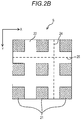
FIG. 2B is a plan view illustrating a configurational example of a sample;
FIG. 2C is a plan view illustrating a configurational example of a sample;
FIG. 3 is a block diagram illustrating an electrical configuration of the scanning probe microscope in FIG. 1;
FIG. 4A is a view for describing a first example of inclination correction and illustrates an example of a surface image of the sample;
FIG. 4B is a view for describing the first example of the inclination correction and illustrates an example of the surface image of the sample;
FIG. 5 is a view for describing a second example of the inclination correction and illustrates an example of a surface image of a sample; and
FIG. 6 is a perspective view illustrating an example of a sample, which is an observation target, and illustrates only a part of the sample.
DETAILED DESCRIPTION
1. Configuration of Scanning Probe Microscope
FIG. 1 is a conceptual diagram illustrating a configurational example of a scanning probe microscope according to an embodiment of the invention. The scanning probe microscope (SPM) includes a cantilever 1, an optical irradiation unit 2, a beam splitter 3, a mirror 4, an optical detection unit 5, and a sample stage 6. The cantilever 1 is caused to move along a surface of a sample S, and thereby it is possible to obtain a surface image (unevenness image) of the sample S placed on the sample stage 6.
For example, the optical irradiation unit 2 includes a laser beam source such as a semiconductor laser and irradiates the cantilever 1 with a light beam. The light beam, with which the optical irradiation unit 2 performs irradiation, is incident to the cantilever 1 through the beam splitter 3. The cantilever 1 is provided with a reflective surface 11, and reflected beam from the reflective surface 11 is reflected from the mirror 4 and is received by the optical detection unit 5. For example, a configuration including a photodiode such as a four-split photodiode can be employed as the optical detection unit 5.
For example, on an optical path from the optical irradiation unit 2 to the cantilever 1, another optical member such as a collimating lens or a focus lens (both lenses not illustrated) may be provided. In this case, after an irradiation beam from the optical irradiation unit 2 is changed into a parallel beam by the collimating lens, the parallel beam can be caused to focus on the focus lens and guided to a side of the cantilever 1.
In addition to the beam splitter 3, the collimating lens, the focus lens, and the like configure an optical system for guiding the irradiation beam from the optical irradiation unit 2 to the cantilever 1. However, the configuration of the optical system is not limited thereto, and a configuration may be employed, in which at least one of the optical members described above is not provided.
For example, the cantilever 1 is a very small member having a length of about 150 μm and a width of about 30 to 40 μm and is provided with a probe 12 on a surface on an opposite side to the reflective surface 11. The probe 12 is caused to move along the surface of the sample S, and thereby it is possible to obtain a surface image of the sample S.
Here, the reflective surface 11 of the cantilever 1 is inclined at a predetermined inclination angle θ with respect to a direction orthogonal to an optical axis L of the irradiation beam from the optical irradiation unit 2. Hence, in a case where the probe 12 of the cantilever 1 is caused to move along unevenness of the surface of the sample S, the cantilever 1 is bent, and the inclination angle θ of the reflective surface 11 changes. In this case, a position on the optical detection unit 5, at which the reflected beam from the reflective surface 11 is received, changes, and thereby a detection signal from the optical detection unit 5 changes. Therefore, it is possible to obtain the surface image of the sample S based on the detection signal from the optical detection unit 5.
In the embodiment, a configuration is employed, in which the cantilever 1 is displaced along the surface of the sample S; however, a configuration may be employed, in which the sample stage 6 is caused to move, and thereby the sample S is displaced with respect to the cantilever 1. In other words, a configuration may be employed, in which the cantilever 1 is relatively displaced along the surface of the sample S.
2. Configuration of Sample
FIGS. 2A to 2C are plan views illustrating a configurational example of the sample S. In a case where the sample S provided with a convex portion 21 and a concave portion 22 on the surface is an observation target, the scanning probe microscope according to the embodiment has a function of being capable of easily performing inclination correction on the surface image of the sample S. When the surface image of the sample S is acquired, the cantilever 1 is relatively displaced along the surface of the sample S in a main-scanning direction (X direction) and a sub-scanning direction (Y direction).
The convex portion 21 and the concave portion 22 formed on the surface of the sample S each have a surface (top surface) having some undulations; however, a step between the convex portion 21 and the concave portion 22 has a larger difference in height than the undulation. In FIGS. 2A to 2C, the convex portion 21 is illustrated by being hatched, and a boundary between a region (convex portion 21), which is hatched, and a region (concave portion 22), which is not hatched, is a step part between the convex portion 21 and the concave portion 22.
In an example in FIG. 2A, a surface of the sample S is provided with a plurality of convex portions 21 extending in a straight line, the convex portions being formed side by side in parallel with concave portions 22 interposed therebetween. Hence, as illustrated in FIG. 2A, in a case where the sample S is placed on the sample stage 6 such that the convex portions 21 extend in parallel with the Y direction, a surface image on which the convex portions 21 and the concave portions 22 appear alternately in the X direction is obtained.
For example, in a case where inclination correction is performed on the surface image of the sample S, luminance of pixels along a straight line 23 parallel to the Y direction is extracted. When the sample S is horizontally placed on the sample stage 6, values of the luminance of pixels extracted along the straight line 23 are substantially the same. However, in a case where the sample S is not horizontally placed on the sample stage 6, a surface, which should be horizontal in a proper posture, is inclined, and variations in the luminance based on such inclination appear on the surface image of the sample S.
In this respect, in the inclination correction, luminance of pixels (for example, pixels along the straight line 23) of the surface image of the surface, which should be horizontal at the proper posture, is extracted, and an image process is performed on the surface image of the sample S by using a mean value, a median value, or the like of values of the luminance of the pixels. Consequently, it is possible to obtain a surface image after the inclination correction by which the variations in the luminance based on the inclination of the sample S are removed.
In an example in FIG. 2B, a surface of the sample S is provided with a plurality of convex portions 21 arranged in a grid pattern, with the concave portions 22 interposed therebetween. Hence, as illustrated in FIG. 2B, in a case where the sample S is placed on the sample stage 6 such that the convex portions 21 are arranged in parallel with the X direction and the Y direction, a surface image on which the convex portions 21 and the concave portions 22 appear alternately in the X direction and the Y direction is obtained.
In a case where the inclination correction is performed on the surface image of the sample S as illustrated in FIG. 2B, it is possible to extract luminance of pixels not only along a straight line 24 parallel to the Y direction but also along a straight line 25 parallel to the X direction. In other words, luminance of the pixels along the straight line 24 or 25 parallel to the Y direction or the X direction, respectively, is extracted, and the inclination correction is performed on the surface image of the sample S based on the luminance of the pixels. In this manner, it is possible to obtain a surface image after the inclination correction.
In an example in FIG. 2C, a surface of the sample S is provided with a plurality of convex portions 21, with the concave portions 22 interposed therebetween; however, a configuration is employed in which the convex portions 21 are not regularly formed, unlike FIG. 2A or 2B. Even in the configuration, it is possible to extract luminance of the pixels along a straight line 26 parallel to the Y direction and to perform the inclination correction on the surface image of the sample S based on the luminance of the pixels.
When it is possible to extract luminance of pixels along a straight line 27 extending not in the Y direction but in a direction intersecting the X direction and the Y direction in the case of the sample S as illustrated in FIG. 2C, it is also possible to perform the inclination correction on the surface image of the sample S based on the luminance of the pixels.
In this manner, the sample S has a flat surface on which it is possible to draw the straight lines (straight lines 23 to 27 or the like) along at least one direction. The flat surface may be a surface along the surface of the concave portion 22 or may be a surface along the surface of the convex portion 21; however, the flat surface is preferably a flat surface on which it is possible to draw a straight line from one side to another side of the surface image of the sample S. Incidentally, the flat surface also includes a surface having some undulations smaller than the step between the convex portion 21 and the concave portion 22, an undulation due to minute foreign matter, or the like.
3. Electrical Configuration
FIG. 3 is a block diagram illustrating an electrical configuration of the scanning probe microscope in FIG. 1. The scanning probe microscope includes a control unit 7, a storage unit 8, a display unit 9, and the like. In addition, although not illustrated in FIG. 1, the scanning probe microscope further includes a cantilever moving mechanism 10 for moving the cantilever 1 in both of the X direction and the Y direction.
For example, the control unit 7 is configured to have a central processing unit (CPU). The CPU executes a program, thereby, functioning as a scanning processor 71, an image acquiring processor 72, an inclination correcting processor 73, an image display processor 74, and the like. For example, the storage unit 8 is configured of a random access memory (RAM), a hard disk, or the like. For example, the display unit 9 is configured of a liquid crystal display or the like, and is capable of displaying various types of images such as the surface image of the sample S.
The scanning processor 71 controls the cantilever moving mechanism 10, thereby relatively displacing the cantilever 1 with respect to the surface of the sample S. Consequently, it is possible to cause the cantilever 1 to scan the surface of the sample S in the main-scanning direction (X direction) and the sub-scanning direction (Y direction).
The image acquiring processor 72 acquires the surface image of the sample S based on a detection signal from the optical detection unit 5 while the scanning processor 71 causes the cantilever 1 to perform scanning. In this case, the luminance of the pixels of the surface image of the sample S has values obtained depending on strength of the detection signal from the optical detection unit 5. The surface image of the sample S, which has been acquired by the image acquiring processor 72, is stored in the storage unit 8.
The inclination correcting processor 73 performs an image process for correcting inclination of the surface image to a Z direction intersecting the X direction and the Y direction on the surface image of the sample S. Specifically, the inclination correcting processor 73 extracts the plurality of pixels from the surface image of the sample S on a straight line along a predetermined direction and corrects the inclination of the surface image in the Z direction based on the luminance of the extracted pixels.
In this case, when a mean value or a median value of values of the luminance of the extracted pixels is set as a reference value, for example, luminance differences between the pixels on the straight line are calculated with respect to the reference value. The luminance differences between the pixels on the straight line are computed to be added to or subtracted from luminance values of pixels aligned in a direction orthogonal to the straight line, and thereby it is possible to perform the inclination correction of the pixels of the entire surface image of the sample S. In the embodiment, the X direction and the Y direction are orthogonal to each other in a horizontal plane, and the Z direction is a vertical direction (refer to FIG. 1); however, the directions are not limited thereto, as long as the X direction, the Y direction, and the Z direction intersect each other.
The image display processor 74 displays, on the display unit 9, the surface image of the sample S after the inclination correction is performed by the inclination correcting processor 73. The image display processor 74 may be capable of displaying the surface image on the display unit 9 after an image process such as a rotation process for rotating the surface image of the sample S other than the inclination correction is performed on the surface image.
4. First Example of Inclination Correction
FIGS. 4A and 4B are views for describing a first example of the inclination correction and illustrate an example of the surface image of the sample S. In this example, the sample S illustrated in FIG. 2A is placed on the sample stage 6 such that the convex portions 21 extend in one direction (P direction) intersecting the X direction and the Y direction, and the surface image (refer to FIG. 4A) of the sample S, which is acquired through scanning performed by the cantilever 1 in this state, is described.
In this case, similar to the case described in FIG. 2A, when luminance of pixels along a straight line parallel to the Y direction is extracted, luminance of pixels along a straight line through the convex portions 21 and the concave portions 22 is extracted. In this manner, it is not possible to appropriately perform the inclination correction. In this respect, in this example, the inclination correcting processor 73 is configured to extract a plurality of pixels which are oblique with respect to the X direction and the Y direction such that a direction (predetermined direction) of a straight line 28 when a plurality of pixels are extracted on one straight line substantially matches the P direction.
For example, a process for extracting an edge (step part between the edge the convex portion 21 and the concave portion 22) from the surface image of the sample S is performed, and an inclination angle of the P direction with respect to the X direction or the Y direction can be determined by calculating an inclination angle of the edge. However, the process is not limited to such a configuration and may employ a configuration in which a user manually inputs the inclination angle, for example.
In this example, in a case where the correction is performed on the surface image of the sample S having the flat surface in the P direction intersecting the X direction and the Y direction, the plurality of pixels are extracted along the P direction, and the inclination of the surface image is corrected, based on the luminance of the extracted pixels (inclination correcting step). Consequently, since luminance of pixels is not extracted along a straight line through the convex portions 21 and the concave portions 22, a user does not need to place the sample S while considering that the P direction needs to extend to be parallel to the X direction or the Y direction. Hence, it is possible to simplify placement work of the sample S.
In particular, in this example, the direction (predetermined direction) when the plurality of pixels are extracted from the surface image of the sample S on the straight line is obliquely set with respect to the X direction and the Y direction, thereby, substantially matching the P direction. Hence, regardless of the direction in which the sample S is placed, it is possible to automatically extract the plurality of pixels along the predetermined direction that substantially matches the P direction and to correct inclination of the surface image based on the luminance of the extracted pixels.
As illustrated in FIG. 4B, the surface image after the correction by the inclination correcting processor 73 may be rotated by the image display processor 74, and then may be displayed on the display unit 9. In this case, the surface image is rotated such that the P direction substantially matches the X direction or the Y direction (Y direction in the example in FIG. 4B). A rotation angle of the surface image in this case can be determined, based on an inclination angle of the P direction with respect to the X direction or the Y direction, which is calculated as described above.
In this manner, the surface image obtained after correcting the inclination is rotated, and thereby the P direction is caused to substantially match the X direction or the Y direction before the rotation, and the surface image (surface image illustrated in FIG. 4B) is displayed. Therefore, the user more easily observes the surface image, than in a case where the surface image (surface image illustrated in FIG. 4A) is displayed in a state in which the P direction is inclined with respect to the X direction and the Y direction as is.
In addition, in this example, the plurality of pixels are extracted from one end portion 281 to another end portion 282 of the surface image of the sample S in the predetermined direction (direction of the straight line 28), and the inclination of the surface image is corrected, based on the luminance of the extracted pixels. Hence, it is possible to correct the inclination of the surface image based on the luminance of more pixels, and thus it is possible to improve accuracy of the inclination correction.
However, the example is not limited to the configuration in which the plurality of pixels are extracted from the one end portion 281 to the other end portion 282 along the straight line 28, and a configuration may be employed, in which only a part of pixels on the straight line 28 are extracted, and the inclination of the surface image is corrected, based on the luminance of the extracted pixels.
5. Second Example of Inclination Correction
FIG. 5 is a view for describing a second example of the inclination correction and illustrates an example of a surface image of the sample S. In this example, the sample S illustrated in FIG. 2A is placed on the sample stage 6 such that the convex portions 21 extend in the one direction (P direction) intersecting the X direction and the Y direction, and a state of rotating the surface image (refer to FIG. 4A) of the sample S, which is acquired through the scanning performed by the cantilever 1 in this state (refer to FIG. 5), is described.
In this example, the direction (predetermined direction) of the straight line 28 when the plurality of pixels are extracted on the one straight line is set to either the X direction or the Y direction before the rotation (in this example, the Y direction) in advance. In this respect, as illustrated in FIG. 5, a configuration is employed in which, after the P direction is caused to substantially match the predetermined direction (direction of the straight line 28) by rotating the surface image of the sample S, the plurality of pixels are extracted.
In this example, in a case where the correction is performed on the surface image of the sample S having the flat surface in the P direction intersecting the X direction and the Y direction, the plurality of pixels are extracted along the P direction, and the inclination of the surface image is corrected, based on the luminance of the extracted pixels (inclination correcting step). Consequently, since luminance of pixels is not extracted along a straight line through the convex portions 21 and the concave portions 22, a user does not need to place the sample S while considering that the P direction needs to extend to be parallel to the X direction or the Y direction. Hence, it is possible to simplify the placement work of the sample S.
In particular, in this example, the surface image of the sample S is rotated, and thereby the direction (predetermined direction) when the plurality of pixels are extracted from the surface image on the straight line substantially matches the P direction. Hence, regardless of the direction in which the sample S is placed, it is possible to automatically extract the plurality of pixels along the predetermined direction that substantially matches the P direction and to correct the inclination of the surface image based on the luminance of the extracted pixels.
In addition, in this example, the plurality of pixels are extracted from the one end portion 281 to the other end portion 282 of the surface image of the sample S in the predetermined direction (direction of the straight line 28), and the inclination of the surface image is corrected, based on the luminance of the extracted pixels. Hence, it is possible to correct the inclination of the surface image based on the luminance of more pixels, and thus it is possible to improve accuracy of the inclination correction.
However, the example is not limited to the configuration in which the plurality of pixels are extracted from the one end portion 281 to the other end portion 282 along the straight line 28, and a configuration may be employed, in which only a part of pixels on the straight line 28 are extracted, and the inclination of the surface image is corrected, based on the luminance of the extracted pixels.
A program for causing a computer to execute a surface image correcting method according to the invention may be provided. In this case, a configuration may be employed, in which the program is provided in a state of being stored in a storage medium, or a configuration may be employed, in which the program is provided via wired communication or wireless communication.

Claims (9)

The invention claimed is:
1. A scanning probe microscope comprising:
a cantilever that is relatively displaced along a surface of a sample;
a scanning processor that performs scanning by causing the cantilever to be relatively displaced with respect to the surface of the sample in both directions of an X direction and a Y direction which intersect each other; and
an inclination correcting processor that performs an image process for correcting inclination of a surface image to a Z direction intersecting the X direction and the Y direction on the surface image of the sample which has been acquired from scanning by the scanning processor,
wherein the inclination correcting processor extracts a plurality of pixels from the surface image on a straight line along a predetermined direction, corrects inclination of the surface image based on luminance of the extracted pixels, and performs an image process such that it is possible to extract the plurality of pixels along the one direction in a case where correction is performed on the surface image of the sample having a flat surface at least in the one direction intersecting the X direction and the Y direction.
2. The scanning probe microscope according to claim 1, wherein, in a case where the correction is performed on the surface image of the sample having the flat surface at least in the one direction, the inclination correcting processor extracts the plurality of pixels which are oblique with respect to the X direction and the Y direction such that the predetermined direction substantially matches the one direction.
3. The scanning probe microscope according to claim 2, further comprising:
an image display processor that rotates the surface image corrected by the inclination correcting processor, substantially matches the one direction to the X direction or the Y direction before rotation, and displays the surface image.
4. The scanning probe microscope according to claim 1, wherein, in a case where correction is performed on the surface image of the sample having the flat surface at least in the one direction, the inclination correcting processor extracts the plurality of pixels after the surface image is rotated such that the one direction substantially matches the predetermined direction.
5. The scanning probe microscope according to claim 1, wherein the inclination correcting processor extracts the plurality of pixels from one end portion to another end portion in the predetermined direction on the surface image.
6. A surface image correcting method for correcting a surface image of a sample which has been acquired by a scanning probe microscope that includes a cantilever that is relatively displaced along a surface of the sample and a scanning processor that performs scanning by causing the cantilever to be relatively displaced with respect to the surface of the sample in both directions of an X direction and a Y direction which intersect each other, the method comprising:
an inclination correcting step of performing an image process for correcting inclination of the surface image to a Z direction intersecting the X direction and the Y direction on the surface image of the sample which has been acquired from scanning by the scanning processor,
wherein, in the inclination correcting step, a plurality of pixels are extracted from the surface image on a straight line along a predetermined direction, inclination of the surface image is corrected based on luminance of the extracted pixels, and an image process is performed such that it is possible to extract the plurality of pixels along the one direction in a case where correction is performed on the surface image of the sample having a flat surface at least in the one direction intersecting the X direction and the Y direction.
7. The surface image correcting method according to claim 6, wherein, in the inclination correcting step, in a case where the correction is performed on the surface image of the sample having the flat surface at least in the one direction, the plurality of pixels which are oblique with respect to the X direction and the Y direction are extracted such that the predetermined direction substantially matches the one direction.
8. The surface image correcting method according to claim 6, wherein, in the inclination correcting step, in a case where the correction is performed on the surface image of the sample having the flat surface at least in the one direction, the plurality of pixels are extracted after the surface image is rotated such that the one direction substantially matches the predetermined direction.
9. The surface image correcting method according to claim 6, wherein, in the inclination correcting step, the plurality of pixels are extracted from one end portion to another end portion in the predetermined direction on the surface image.
US16/184,013 2018-03-08 2018-11-08 Scanning probe microscope and surface image correction method Active US10564183B2 (en)

Applications Claiming Priority (2)

Application Number Priority Date Filing Date Title
JP2018041693A JP6631647B2 (en) 2018-03-08 2018-03-08 Scanning probe microscope and surface image correction method
JP2018-041693 2018-03-08

Publications (2)

Publication Number Publication Date
US20190277882A1 US20190277882A1 (en) 2019-09-12
US10564183B2 true US10564183B2 (en) 2020-02-18

Family

ID=67843898

Family Applications (1)

Application Number Title Priority Date Filing Date
US16/184,013 Active US10564183B2 (en) 2018-03-08 2018-11-08 Scanning probe microscope and surface image correction method

Country Status (3)

Country Link
US (1) US10564183B2 (en)
JP (1) JP6631647B2 (en)
CN (1) CN110244085B (en)

Families Citing this family (1)

* Cited by examiner, † Cited by third party
Publication number Priority date Publication date Assignee Title
WO2024014185A1 (en) * 2022-07-11 2024-01-18 株式会社島津製作所 Image processing method, image processing device, scanning probe microscope, and program

Citations (5)

* Cited by examiner, † Cited by third party
Publication number Priority date Publication date Assignee Title
US20010033713A1 (en) * 2000-04-04 2001-10-25 Harris Martin Russell Z sharpening for fibre confocal microscopes
US20040238731A1 (en) * 2001-11-02 2004-12-02 Olympus Corporation Confocal scanning microscope
US20070115457A1 (en) * 2005-11-15 2007-05-24 Olympus Corporation Lens evaluation device
US20120138814A1 (en) * 2010-12-03 2012-06-07 Carl Zeiss Nts Ltd. Particle beam device with deflection system
JP2014211372A (en) 2013-04-19 2014-11-13 株式会社島津製作所 Scanning type probe microscope

Family Cites Families (9)

* Cited by examiner, † Cited by third party
Publication number Priority date Publication date Assignee Title
US5576543A (en) * 1995-08-21 1996-11-19 Texsem Laboratories, Inc. Method and apparatus for determining crystallographic characteristics
JP3460811B2 (en) * 1999-12-24 2003-10-27 日本電気株式会社 Image input device and method
KR100946888B1 (en) * 2003-01-30 2010-03-09 삼성전자주식회사 Device and method for correcting tilt of a subject in a video screen
JP3892838B2 (en) * 2003-10-16 2007-03-14 ファナック株式会社 3D measuring device
CN1300562C (en) * 2004-02-26 2007-02-14 上海大学 Model parameter calibrating and nontinear correcting method of piezoelectric actuator in scanning probe microscope
WO2010140609A1 (en) * 2009-06-02 2010-12-09 株式会社ニコン Image processing device, program and microscope
JP2011188083A (en) * 2010-03-05 2011-09-22 Sony Corp Information processing apparatus, information processing method, program, and imaging apparatus including optical microscope
JP5865113B2 (en) * 2012-02-20 2016-02-17 株式会社Pfu Image processing apparatus, image processing system, image processing method, and image processing program
EP2735866A1 (en) * 2012-11-27 2014-05-28 Fei Company Method of sampling a sample and displaying obtained information

Patent Citations (5)

* Cited by examiner, † Cited by third party
Publication number Priority date Publication date Assignee Title
US20010033713A1 (en) * 2000-04-04 2001-10-25 Harris Martin Russell Z sharpening for fibre confocal microscopes
US20040238731A1 (en) * 2001-11-02 2004-12-02 Olympus Corporation Confocal scanning microscope
US20070115457A1 (en) * 2005-11-15 2007-05-24 Olympus Corporation Lens evaluation device
US20120138814A1 (en) * 2010-12-03 2012-06-07 Carl Zeiss Nts Ltd. Particle beam device with deflection system
JP2014211372A (en) 2013-04-19 2014-11-13 株式会社島津製作所 Scanning type probe microscope

Also Published As

Publication number Publication date
US20190277882A1 (en) 2019-09-12
CN110244085B (en) 2022-03-11
CN110244085A (en) 2019-09-17
JP6631647B2 (en) 2020-01-15
JP2019158387A (en) 2019-09-19

Similar Documents

Publication Publication Date Title
US9865046B2 (en) Defect inspection method and defect inspection device
KR102883767B1 (en) Defect inspection method, defect inspection device
US20100150415A1 (en) Retinal scanning
US9945661B2 (en) Method for measuring height, non-transitory computer readable medium storing a program for measuring height, and height measuring apparatus
US20230154774A1 (en) Inspection device and inspection method
US10867771B2 (en) Electron microscope and specimen tilt angle adjustment method
US20170322408A1 (en) Illumination setting method, light sheet microscope apparatus, and recording medium
KR20210069690A (en) How to record images using a particle microscope
US10564183B2 (en) Scanning probe microscope and surface image correction method
US10641790B2 (en) Scanning probe microscope
JP2002270126A (en) Electron beam device, data processing device for electron beam device, stereo data creating method for electron beam device
JP5136108B2 (en) 3D shape measuring method and 3D shape measuring apparatus
US10521922B2 (en) End face inspection device and focused image data acquisition method therefor
US7538868B2 (en) Pattern recognition matching for bright field imaging of low contrast semiconductor devices
JP2002228421A (en) Scanning laser microscope
JP2002270127A (en) Data processing device for electron beam device, stereo measurement method for electron beam device
JP5491817B2 (en) Thin film sample position recognition system in electron microscope
JP2002203507A (en) Concavo-convex image forming apparatus and electron beam analyzer
JP5191265B2 (en) Optical microscope apparatus and data processing apparatus for optical microscope
US11659999B2 (en) OCT system, method of generating OCT image and storage medium
US11915908B2 (en) Method for measuring a sample and microscope implementing the method
WO2025046929A1 (en) Image processing method and electron microscope system
JP6660774B2 (en) Height data processing device, surface shape measuring device, height data correction method, and program
CN116344304A (en) Method and system for determining beam position
JP7126960B2 (en) electronic microscope

Legal Events

Date Code Title Description
AS Assignment

Owner name: SHIMADZU CORPORATION, JAPAN

Free format text: ASSIGNMENT OF ASSIGNORS INTEREST;ASSIGNOR:HIRADE, MASATO;REEL/FRAME:047452/0695

Effective date: 20181029

FEPP Fee payment procedure

Free format text: ENTITY STATUS SET TO UNDISCOUNTED (ORIGINAL EVENT CODE: BIG.); ENTITY STATUS OF PATENT OWNER: LARGE ENTITY

STPP Information on status: patent application and granting procedure in general

Free format text: NOTICE OF ALLOWANCE MAILED -- APPLICATION RECEIVED IN OFFICE OF PUBLICATIONS

STPP Information on status: patent application and granting procedure in general

Free format text: PUBLICATIONS -- ISSUE FEE PAYMENT VERIFIED

STCF Information on status: patent grant

Free format text: PATENTED CASE

MAFP Maintenance fee payment

Free format text: PAYMENT OF MAINTENANCE FEE, 4TH YEAR, LARGE ENTITY (ORIGINAL EVENT CODE: M1551); ENTITY STATUS OF PATENT OWNER: LARGE ENTITY

Year of fee payment: 4