US10562053B2 - Liquid dispensing device having a pre-compression outlet valve - Google Patents
Liquid dispensing device having a pre-compression outlet valve Download PDFInfo
- Publication number
- US10562053B2 US10562053B2 US15/112,675 US201515112675A US10562053B2 US 10562053 B2 US10562053 B2 US 10562053B2 US 201515112675 A US201515112675 A US 201515112675A US 10562053 B2 US10562053 B2 US 10562053B2
- Authority
- US
- United States
- Prior art keywords
- piston
- valve
- dispensing device
- liquid dispensing
- piston chamber
- Prior art date
- Legal status (The legal status is an assumption and is not a legal conclusion. Google has not performed a legal analysis and makes no representation as to the accuracy of the status listed.)
- Active, expires
Links
- 239000007788 liquid Substances 0.000 title claims abstract description 105
- 230000006835 compression Effects 0.000 title description 35
- 238000007906 compression Methods 0.000 title description 35
- 230000037452 priming Effects 0.000 claims abstract description 16
- 238000007789 sealing Methods 0.000 claims description 41
- 230000002093 peripheral effect Effects 0.000 claims description 6
- 239000012530 fluid Substances 0.000 claims description 4
- 238000004891 communication Methods 0.000 claims description 3
- 239000003570 air Substances 0.000 description 40
- 239000007921 spray Substances 0.000 description 14
- 230000003139 buffering effect Effects 0.000 description 13
- 238000005336 cracking Methods 0.000 description 11
- 238000013022 venting Methods 0.000 description 10
- JXSJBGJIGXNWCI-UHFFFAOYSA-N diethyl 2-[(dimethoxyphosphorothioyl)thio]succinate Chemical compound CCOC(=O)CC(SP(=S)(OC)OC)C(=O)OCC JXSJBGJIGXNWCI-UHFFFAOYSA-N 0.000 description 9
- 238000009826 distribution Methods 0.000 description 6
- 239000000463 material Substances 0.000 description 6
- 239000000443 aerosol Substances 0.000 description 5
- 230000009471 action Effects 0.000 description 4
- 238000005516 engineering process Methods 0.000 description 4
- 239000012528 membrane Substances 0.000 description 4
- 238000005507 spraying Methods 0.000 description 4
- -1 Raid®) Substances 0.000 description 3
- 230000001419 dependent effect Effects 0.000 description 3
- 239000006260 foam Substances 0.000 description 3
- 239000004479 aerosol dispenser Substances 0.000 description 2
- 239000012080 ambient air Substances 0.000 description 2
- 238000004140 cleaning Methods 0.000 description 2
- 238000010586 diagram Methods 0.000 description 2
- 238000006073 displacement reaction Methods 0.000 description 2
- 238000004519 manufacturing process Methods 0.000 description 2
- 230000007246 mechanism Effects 0.000 description 2
- 238000004806 packaging method and process Methods 0.000 description 2
- 238000003825 pressing Methods 0.000 description 2
- 239000003380 propellant Substances 0.000 description 2
- 230000000284 resting effect Effects 0.000 description 2
- 241000238631 Hexapoda Species 0.000 description 1
- 239000004952 Polyamide Substances 0.000 description 1
- 239000004698 Polyethylene Substances 0.000 description 1
- 239000004743 Polypropylene Substances 0.000 description 1
- 230000015572 biosynthetic process Effects 0.000 description 1
- 230000008859 change Effects 0.000 description 1
- 238000010411 cooking Methods 0.000 description 1
- 230000000994 depressogenic effect Effects 0.000 description 1
- 230000000694 effects Effects 0.000 description 1
- 239000000383 hazardous chemical Substances 0.000 description 1
- 230000003116 impacting effect Effects 0.000 description 1
- 239000004615 ingredient Substances 0.000 description 1
- 239000000314 lubricant Substances 0.000 description 1
- 230000003278 mimic effect Effects 0.000 description 1
- 239000002245 particle Substances 0.000 description 1
- 229920002647 polyamide Polymers 0.000 description 1
- 229920000573 polyethylene Polymers 0.000 description 1
- 229920006324 polyoxymethylene Polymers 0.000 description 1
- 229920001155 polypropylene Polymers 0.000 description 1
- 238000005381 potential energy Methods 0.000 description 1
- 230000036316 preload Effects 0.000 description 1
- 230000002265 prevention Effects 0.000 description 1
- 238000005086 pumping Methods 0.000 description 1
- 238000003892 spreading Methods 0.000 description 1
- 230000007480 spreading Effects 0.000 description 1
- 230000001360 synchronised effect Effects 0.000 description 1
- 230000007704 transition Effects 0.000 description 1
Images


Classifications
-
- B—PERFORMING OPERATIONS; TRANSPORTING
- B05—SPRAYING OR ATOMISING IN GENERAL; APPLYING FLUENT MATERIALS TO SURFACES, IN GENERAL
- B05B—SPRAYING APPARATUS; ATOMISING APPARATUS; NOZZLES
- B05B11/00—Single-unit hand-held apparatus in which flow of contents is produced by the muscular force of the operator at the moment of use
- B05B11/01—Single-unit hand-held apparatus in which flow of contents is produced by the muscular force of the operator at the moment of use characterised by the means producing the flow
- B05B11/10—Pump arrangements for transferring the contents from the container to a pump chamber by a sucking effect and forcing the contents out through the dispensing nozzle
- B05B11/1042—Components or details
- B05B11/1061—Pump priming means
-
- B—PERFORMING OPERATIONS; TRANSPORTING
- B05—SPRAYING OR ATOMISING IN GENERAL; APPLYING FLUENT MATERIALS TO SURFACES, IN GENERAL
- B05B—SPRAYING APPARATUS; ATOMISING APPARATUS; NOZZLES
- B05B11/00—Single-unit hand-held apparatus in which flow of contents is produced by the muscular force of the operator at the moment of use
- B05B11/01—Single-unit hand-held apparatus in which flow of contents is produced by the muscular force of the operator at the moment of use characterised by the means producing the flow
- B05B11/10—Pump arrangements for transferring the contents from the container to a pump chamber by a sucking effect and forcing the contents out through the dispensing nozzle
- B05B11/1001—Piston pumps
- B05B11/1009—Piston pumps actuated by a lever
- B05B11/1012—Piston pumps actuated by a lever the pump chamber being arranged substantially coaxially to the neck of the container
-
- B05B11/3061—
-
- B—PERFORMING OPERATIONS; TRANSPORTING
- B05—SPRAYING OR ATOMISING IN GENERAL; APPLYING FLUENT MATERIALS TO SURFACES, IN GENERAL
- B05B—SPRAYING APPARATUS; ATOMISING APPARATUS; NOZZLES
- B05B11/00—Single-unit hand-held apparatus in which flow of contents is produced by the muscular force of the operator at the moment of use
- B05B11/01—Single-unit hand-held apparatus in which flow of contents is produced by the muscular force of the operator at the moment of use characterised by the means producing the flow
- B05B11/10—Pump arrangements for transferring the contents from the container to a pump chamber by a sucking effect and forcing the contents out through the dispensing nozzle
- B05B11/1001—Piston pumps
- B05B11/1009—Piston pumps actuated by a lever
- B05B11/1012—Piston pumps actuated by a lever the pump chamber being arranged substantially coaxially to the neck of the container
- B05B11/1014—Piston pumps actuated by a lever the pump chamber being arranged substantially coaxially to the neck of the container the pump chamber being arranged substantially coaxially to the container
-
- B—PERFORMING OPERATIONS; TRANSPORTING
- B05—SPRAYING OR ATOMISING IN GENERAL; APPLYING FLUENT MATERIALS TO SURFACES, IN GENERAL
- B05B—SPRAYING APPARATUS; ATOMISING APPARATUS; NOZZLES
- B05B11/00—Single-unit hand-held apparatus in which flow of contents is produced by the muscular force of the operator at the moment of use
- B05B11/01—Single-unit hand-held apparatus in which flow of contents is produced by the muscular force of the operator at the moment of use characterised by the means producing the flow
- B05B11/10—Pump arrangements for transferring the contents from the container to a pump chamber by a sucking effect and forcing the contents out through the dispensing nozzle
- B05B11/1038—Pressure accumulation pumps, i.e. pumps comprising a pressure accumulation chamber
- B05B11/104—Pressure accumulation pumps, i.e. pumps comprising a pressure accumulation chamber the outlet valve being opened by pressure after a defined accumulation stroke
-
- B05B11/3014—
-
- B05B11/304—
Definitions
- the present invention relates to dispensing technologies, and in particular to improved sprayers or foam dispensers of various types, wherein output pressure, and thus droplet size, can be precisely controlled, wherein sprayers can be efficiently primed to remove air form the pumping system, and where outlet valves optimally perform with minimal hysteresis.
- the invention relates to a liquid dispensing device comprising: a piston chamber; a piston that is moveable within the piston chamber to pressurise a liquid to be dispensed; a nozzle with a defined throughput for dispensing the liquid; an outlet valve having a defined minimum opening pressure arranged between the piston chamber and the nozzle; and a prime valve for priming the device.
- a liquid dispensing device is disclosed in applicant's earlier application PCT/US2013/068825, which was later published as WO 2014/074654 A1.
- Liquid dispensing devices such as spray bottles are well known. Some offer pre-compression so as to insure a strong spray when the trigger is pulled and prevent leakage. Sprayers and foamers can be easily manufactured and filled, and are often used to dispense cleaners of all types, for example. However, in many circumstances it is preferred not to have to continually pump a dispensing device to push out the dispensed liquid. Rather, it would be much more convenient to be able to continue the spray or foam substantially past the user pulling a trigger or otherwise actuating the sprayer head. For example, if by actuating a sprayer head a certain reasonable number of times per minute a continuous spray could be obtained, many users would find that optimal.
- Aerosol dispensers such as are used for cooking spray (e.g. Pam®), insect spray (e.g. Raid®), lubricants (e.g. WD-40®), and a host of other uses. Aerosols hold a liquid or other dispensate under pressure such that when a user activates the device (e.g., by pressing a button) the pressurized contents are allowed to escape.
- aerosols present both significant environmental hazards as well as packaging drawbacks, which result from the necessity of using an aerosol propellant in them, and the further necessity of pressurizing them. This requires filling such devices under pressure, using packaging strong enough to withstand the pressure, and taking steps to insure that the propellant maintains a uniform pressure over the life of the can or container. Such conditions often require use of non-environmentally friendly materials and ingredients.
- a conventional sprayer starts dispensing at a low pressure.
- the pressure rises up to a peak pressure.
- the liquid is forced through an orifice, but only a part of the liquid can pass the nozzle, so the pressure will build up within the sprayer.
- the liquid pressure drops to zero. The low pressure at the beginning and end of the stroke thus creates larger, non-uniform droplets at the right and left sides of the conventional sprayer pressure time curve.
- a pre-compression sprayer starts spraying when the liquid pressure is at a pre-determined pressure.
- This pre-determined pressure is known as the “cracking pressure” of the outlet valve.
- the pressure rises to a peak pressure.
- a predetermined pressure closing pressure of the outlet valve
- the droplet size at the beginning and end of a dispensing stroke in a pre-compression sprayer are smaller because the pressure is higher.
- the peak pressure, creating even smaller droplets, is also higher than that of a conventional sprayer, because the same amount of liquid is dispensed in a shorter time. Therefore more pressure builds up.
- the pressure difference across the pressure time curve will still be there and even be greater. It is only shifted to a higher pressure range.
- difficulties with standard pre-compression sprayers include, for example, (1) wider spreading droplet sizes, and (2) too small droplet sizes.
- a buffer may be used in combination with a pre-compression valve. This results in a precise band of outlet pressures, and moves the upper portion of the pressure-time curve to the time interval between downstrokes, as described in detail in WO 2014/074654 A1 referenced above.
- a pre-compression valve which sets the minimum output pressure, may require a significant opening pressure. This makes priming an issue, as to evacuate the air in the pump through the outlet valve requires sufficiently compressing it to reach the opening pressure of the outlet valve.
- a priming system is desirable that does not require venting trapped air through the normal spray outlet channel by opening a pre-compression valve.
- a liquid dispensing device of the type described above wherein the prime valve is mechanically operable and is arranged on or in the piston.
- Mechanical operation of the prime valve allows the pump to be efficiently primed, even though air in the pump cannot be pressurised to the cracking pressure of the outlet valve, while arrangement of the prime valve on or in the piston allows for an easy discharge of the air from the piston chamber.
- liquid dispensing device further comprises an operating member in the piston chamber which is arranged to move the prime valve from a closed position to an open position when the moveable piston is near or at an end of its stroke. In this way the prime valve is opened only at the end of the stroke, when the air is fully pressurised.
- This operation may be achieved in a structurally simple manner when the operating member protrudes from an end wall of the piston chamber.
- the liquid dispensing device may comprise a plurality of operating members.
- An embodiment of the prime valve which is structurally simple comprises a sealing part closing off an orifice in the piston and an actuating part connected to the sealing part and arranged to cooperate with the operating member. By dispensing the air through the orifice in the piston a relatively short flow path is obtained.
- the sealing part may be deformable together with the actuating part when the actuating part is engaged by the operating member.
- a deformable prime valve is easier to manufacture and simpler to operate than a valve that is hinged or otherwise movable.
- an end wall of the piston chamber and/or the piston may comprise an air flow path leading to the prime valve.
- the prime valve may be arranged to be biased towards an open position when a pressure in the piston chamber exceeds a predetermined value.
- the prime valve may also serve as an overpressure relief valve that will open when the pressure within the piston chamber reaches values that are critically high.
- the prime valve is arranged to be biased towards a closed position by a pressure in the piston chamber. In this way leakage of liquid through the prime valve during regular operation of the device may be prevented.
- Such leakage prevention may be achieved by orienting the sealing part towards an end wall of the piston chamber.
- the piston chamber may be cylindrical, the piston may have a circular circumference and the prime valve may be annular, wherein the sealing part of the prime valve may be formed by an outer peripheral edge portion thereof.
- the actuating part may then comprise an annular rim that is concentric with the sealing part and has a smaller diameter than the sealing part.
- sealing part and the actuating part may have substantially parallel orientations when the prime valve is also used as an overpressure valve.
- the sealing part and the actuating part may have substantially opposite orientations in case the prime valve is arranged to prevent leakage of pressurised liquid when the device is normally operated.
- the liquid dispensing device may further comprise a return opening in a side wall of the piston chamber, while the piston may comprise a first circumferential seal for sealing a part of the piston chamber between the piston and a piston chamber end wall and a second circumferential seal spaced apart from the first circumferential seal, such that when the piston is at or near an end of its stroke the return opening is located between the first and second circumferential seals. In this way the space between the first and second seals may serve to collect and discharge the air that is to be removed from the device.
- the liquid dispensing device may further comprise a vent opening in the side wall of the piston chamber, and the first and second circumferential seals may be located between the vent opening and the piston chamber end wall when the piston is at or near an end of its stroke.
- the container may be vented to prevent a (partial) vacuum from developing, and the vent opening may be opened at the end of the stroke, when the seals have passed by the vent opening.
- a liquid dispensing device may be provided wherein the outlet valve may be configured to minimize a difference between its opening pressure and its closing pressure. In this way hysteresis is minimized.
- the outlet valve may comprise a dome and the dome may have a stiffness which varies in radial direction.
- the dome valve may have an inner flexible portion surrounding its center and an outer stiffer portion. This particular stiffness distribution is believed to provide advantageous valve characteristics.
- This stiffness distribution may be obtained by simple means when the dome valve is thinnest in the inner flexible portion, having a radius R 1 , and gets thicker as the radius increases beyond R 1 .
- liquid dispensing device may further comprise a buffer arranged between the piston chamber and the outlet valve.
- a complete, ready-to-use liquid dispensing device is obtained when the device further comprises a container for the liquid to be dispensed, the container being in fluid communication with the piston chamber through an inlet valve.
- the various functional elements may be arranged on or integrated into a dispensing head, which may be mounted on the container.
- one or more of the functional elements may be arranged on or integrated in the container, thus providing so-called “lock-out” features which prevent the applicant's dispensing head from being retrofitted to a container from a competitor.
- FIG. 1 shows dispensing characteristics of various types of sprayers, showing pressure as a function time
- FIG. 2 shows a similar curve for a dispenser characteristic including a preferred range of pressures
- FIG. 3 is a hydraulic scheme representing a liquid dispensing device in accordance with an embodiment of the invention
- FIG. 4 is a perspective view of a physical embodiment of the liquid dispensing device of FIG. 3 without a reservoir or container,
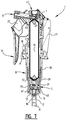
- FIG. 5 is a longitudinal sectional view in the direction of the arrows V-V in FIG. 4 ,
- FIG. 6 is a longitudinal section of the lower part of the device of FIG. 5 and the container with the liquid to be dispensed, in which the device is shown in its initial state, before priming,
- FIG. 7 is a longitudinal sectional view corresponding with FIG. 5 , but showing the device at the end of a pump stroke, with its trigger actuator depressed and its piston in the lowermost position,
- FIG. 8 is a view corresponding with FIG. 6 but showing the piston in its lowermost position during priming, when still some of the air has to escape,
- FIG. 9 is a perspective view of a prime valve as used in the liquid dispensing device of FIGS. 4-8 .
- FIG. 10 is a detailed view on enlarged scale showing the deformation of the prime valve during priming
- FIG. 11 is a cross-sectional perspective detailed view on enlarged scale of the bottom of the piston chamber and the inlet valve
- FIG. 12 is a cross-sectional detailed view of a piston carrying an alternative embodiment of the prime valve and a piston chamber having alternative operating members,
- FIG. 13 is a cross-sectional detailed view corresponding to FIGS. 6 and 8 , which shows the device in combination with a conventional single walled container which must be vented during dispensing,
- FIG. 14 shows a longitudinal sectional view of a dispensing head of an alternative embodiment of the liquid dispensing device, taken along line XIV-XIV in FIG. 15 ,
- FIG. 15 shows a longitudinal sectional view of the alternative embodiment taken along the line XV-XV in FIG. 14 ,
- FIG. 16 is a detailed view of the part indicated by circle XVI in FIG. 15 , with the piston in a raised position prior to priming,
- FIG. 17 is a view corresponding to FIG. 16 but showing the piston in its lowermost position during priming
- FIG. 18 is a view corresponding with FIG. 17 and showing how a container may be vented
- FIG. 19 is a detailed view of the top of the dispensing device as shown in FIGS. 5 and 7 , with the outlet valve being closed,
- FIG. 20 is a view corresponding with FIG. 19 but showing the outlet valve opened and liquid being dispensed
- FIG. 21 is a detailed view of an alternative embodiment of the outlet valve of FIG. 19 in closed position
- FIG. 22 is a view corresponding with FIG. 21 but showing the valve in open position
- FIGS. 23 and 24 are views which correspond with FIGS. 21 and 22 but show yet another embodiment of the outlet valve.
- various novel sprayers and related dispensing devices are presented.
- the sprayer heads shown can, in general, work with both standard bottles or reservoirs and with the “bag within a bag” or “container within a container” Flair® technology developed and provided by the applicant.
- the “bag within a bag” Flair® technology which causes the inner container to shrink around the product, thus obviates headspace or air bubbles in the inner container. Because in Flair® technology the pressure applied to the inner bag results from a pressurizing medium, often atmospheric pressure vented between said inner and outer containers, venting of the liquid container is not required.
- the pressure has to be equalized in the gap between the outer container and the inner container.
- a displacing medium such as, for example, air, whether at atmospheric pressure or higher.
- venting the gap to ambient air somewhere between the inner container and the outer container, for example, by providing a vent on the bottom of the Flair® container, or at any other convenient position of the outer container. In some exemplary embodiments such a vent may be moved to the sprayer head itself.
- a pre-compression sprayer has a different output curve with a different distribution of pressures and droplet sizes, as illustrated by the striped area ( FIG. 1B ). Notably there is a larger range of pressures that are output from a pre-compression sprayer.
- a pre-compression sprayer has normally closed valves. The outlet valve therefore only opens at a predetermined pressure. The displacement volume between inlet and outlet valve of the pump is to become zero during a compression stroke. If it does not, the pump cannot prime. When the piston is actuated by a user the sprayer only starts dispensing when the liquid pressure is above the cracking pressure of the outlet valve. Therefore slow actuation of the pump will give no drips because the pump starts dispensing at a higher pressure. In a pre-compression sprayer performance is less dependent upon the user's operating behavior than in the case of a conventional sprayer.
- a buffering pre-compression sprayer has normally closed valves just as in the case of a non-buffering pre-compression sprayer. Therefore the outlet valve only opens at a predetermined pressure.
- the buffer stores the overflow of liquid, thus preventing peak pressures as in systems with pre-compression valves, but no buffer.
- the synchronized components of the buffering pre-compression sprayer determine the output performance. Fast or slow triggering by a user has little effect on the output, because the pressures are equalized through buffering. The performance of a buffering pre-compression dispenser is thus very minimally dependent upon the operating behavior of the user.
- FIG. 2 illustrates further details of the correlations between elements of a buffering pre-compression sprayer.
- the opening pressure of the outlet responsible for the larger droplet sizes and the maximum dispensing pressure, responsible for the smaller droplet sizes, are the controls which can be used to set the limits of the pressure range/droplet size spread.
- the right side of FIG. 2 illustrates a desired pressure level/droplet size which can be provided by a specification or by a user or by a customer.
- a buffering pre-compression sprayer Given the desired pressure level/droplet size a buffering pre-compression sprayer can be created which outputs a range of pressures or droplet sizes centered on the desired pressure size and running from p minus ⁇ p and p plus ⁇ p.
- the p minus ⁇ p is the opening or cracking pressure p crack of the outlet valve and the p plus ⁇ p is the maximum dispensing pressure p max at a certain stroke rate.
- FIG. 3 is a schematic hydraulic diagram of a liquid dispensing device 1 according to an exemplary embodiment of the present invention.
- a reservoir or container 3 that is filled with the liquid L to be dispensed.
- This can be a Flair® type bag-in-a-bottle or container-in-a-bottle reservoir, as described above.
- an inlet valve 16 which is a one-way valve, and which allows liquid L to enter a piston chamber 4 from the container 3 when an under-pressure is created by movement of a piston 5 in the piston chamber 4 . Through the inlet valve 16 the liquid L enters the piston chamber 4 and is pushed upwards into a buffer chamber through a one-way valve 31 .
- the liquid L flows past a buffer 19 and if there is enough pressure developed pushes open an outlet valve 7 , which allows the liquid to pass through an outlet channel 49 to a nozzle 6 . It is also noted that to the left of the inlet valve 16 there is shown a prime valve 40 which will be described in greater detail below.
- FIGS. 4 and 5 depict an exemplary sprayer engine according to an exemplary embodiment of the present invention, and its various compliment parts. It is noted that the terms “sprayer engine” and “dispensing head” may be used interchangeably throughout this description to define the combination of functional elements that allow a liquid to be dispensed from a container.
- the liquid dispensing device 1 as shown in FIGS. 4 and 5 which is a physical embodiment of the hydraulic scheme of FIG. 3 , comprises a dispensing head 2 and a container 3 that is filled with the liquid L to be dispensed.
- the container can be a Flair® type container ( FIGS. 6, 8 ) or a conventional single wall container ( FIG. 13 ).
- the dispensing head 3 includes a piston chamber 4 , a piston 5 that is reciprocatingly movable within the piston chamber 4 to pressurize the liquid L to be dispensed, and a nozzle 6 with a defined throughput for dispensing the liquid L.
- An outlet valve 7 having a defined minimum opening pressure p crack is arranged between the piston chamber 4 and the nozzle 6 .
- the piston chamber 4 is formed at a tubular lower end of a housing 8 , which extends partly into the container 3 .
- the housing 8 further includes an annular collar 9 for connecting the dispensing head 2 to a neck 10 of the container 3 , e.g. by means of a snap connection or a threaded connection.
- a tubular protrusion 11 for receiving a dip tube (not shown) which may serve to transport the liquid L from a point near the bottom of the container 3 to the piston chamber 4 .
- the tubular protrusion 11 is connected to an inlet opening 12 that is formed in a bottom wall 13 of the piston chamber 4 .
- This bottom wall 13 has an upwardly curved contour surrounding a central recess 14 in which an insert 15 defining a valve seat and an inlet valve 16 are accommodated.
- the housing 8 Extending upward from the collar 9 the housing 8 comprises a support frame 17 which serves as a backbone for supporting and guiding the moving parts of the dispensing head 2 .
- These moving parts include a slider 18 which carries the piston 5 at its lower end and the outlet valve 7 and nozzle 6 at its upper end.
- the slider 18 is hollow and accommodates a buffer 19 which will be discussed below.
- the moving parts of the dispensing head 2 further include an actuator 20 , in the illustrated embodiment a trigger that is pivotally supported by the support frame 17 .
- the trigger 20 includes two side walls 21 extending on opposite sides of the slider 18 , and each having an extension 22 that includes a contoured part cooperating with a pivot shaft (not shown here) on the slider 18 and that further carries a biasing member 23 .
- each biasing member 23 has the form of curved flexion spring, one end 24 of which is attached to the extension 22 , while the opposite free end 25 is restrained by a stop 26 protruding from the housing 8 so as to bend and preload the spring 23 .
- an opening 27 is formed which allows the trigger actuator 20 to freely pivot without interference from the nozzle 6 or an outlet valve assembly 47 .
- the slider 18 is hollow and has an inlet opening 28 at its bottom and an outlet opening 29 at its top.
- the inlet opening 28 communicates with a central opening 30 in the piston 5 , which is closed off by a one-way valve or check valve 31 .
- the outlet opening 29 is closed off by the outlet valve 7 .
- the buffer 19 is a gas filled flexible bag, the internal pressure of which is higher than the cracking pressure of the outlet valve 7 .
- the liquid can flow from the inlet 28 to the outlet 29 through grooves (not shown here) that are formed in the inner surface of the slider 18 .
- the buffer 19 will be compressed to provide space between the bag and the wall of the slider 18 to accommodate the excess liquid.
- the lowermost portion 32 of the housing 8 which defines the piston chamber 4 has a diameter that is smaller than the diameter of a central portion 33 of the housing 8 , which receives the slider 18 .
- the lowermost portion 32 and the central portion 33 are connected by a tapering portion 34 .
- the piston 5 has a similar configuration, with a lowermost portion 35 protruding from the slider 18 and having a relatively narrow diameter, a tapering transition part 36 and an uppermost portion 37 surrounding the slider 18 and having a diameter that is between the diameter of the central portion 33 of the housing 8 and the outer diameter of the slider 18 .
- the piston 5 is provided with outwardly flaring upper and lower edges 38 , 39 . These outwardly flaring edges 38 , 39 are sealingly slidable along the inner wall of the corresponding parts of the housing 8 so as to form upper and lower seals of the piston 5 .
- the liquid dispensing device 1 includes a prime valve 40 that is separate from the outlet valve 7 .
- the prime valve 40 is arranged on the piston, in this embodiment on the side of the piston 5 facing the bottom wall 13 of the piston chamber 4 .
- the prime valve 40 is mechanically operable, i.e. its operation is independent of the pressure of the air that is present in the device 1 .
- the prime valve 40 is operable by an operating member 41 which is arranged in the piston chamber 4 .
- the operating member 41 may be a protrusion that is arranged on the bottom wall 13 of the piston chamber 4 .
- the prime valve 40 is normally biased to a closed position, so that closing of the prime valve 40 does not require action from the operating member 41 .
- Prime valve 40 will open when engaged by the operating member 41 and will automatically close as soon as the engagement ends.
- the prime valve 40 is resiliently deformable and opens when it is deformed by the operating member 41 .
- the prime valve 40 is formed by an annular member that has a central part 42 which snugly fits in an annular groove 43 in the bottom of the piston 5 .
- the prime valve 40 has an outer peripheral edge 44 which is relatively flexible and which seals against an inner surface 45 of an outer peripheral wall 48 of the piston 5 .
- This flexible sealing part 44 is resiliently deformable when the operating member 41 engages the prime valve 40 . Due to its resilience, the sealing part 44 returns to its original position as soon as the engagement with the operating member 41 ends.
- the operating member 41 does not directly engage the sealing part 44 , in order to avoid damage to this sealing part 44 , which might lead to leakage. Instead the operating member 41 engages an actuating part 46 of the prime valve 40 ( FIG. 10 ).
- This actuating part 46 is formed by an annular rim that is arranged radially inwards from the outer sealing edge 44 .
- the actuating part 46 and the sealing part 44 have substantially opposite orientations. Whereas the actuating part 46 is upwardly inclined for smooth engagement with the operating member 41 , which upwardly protrudes from the end wall 13 , the sealing part 44 is inclined downwardly, more or less parallel with the outwardly flared lower edge 39 of the piston 5 . In this way the sealing part 44 is always biased to a closed position by the pressure in the piston chamber 5 . This arrangement prevents leakage of both air and liquid under any circumstances.
- the sealing part 44 and the actuating part 46 may be substantially parallel or even in line with each other ( FIG. 12 ).
- the actuating part 46 is upwardly inclined, and so is the sealing part 44 .
- the sealing part 44 may be urged away from the inner wall 45 of the piston 5 when the pressure in the piston chamber 4 exceeds a predetermined level.
- the prime valve 40 also functions as an overpressure relief valve.
- the flexibility of the sealing part 44 should be selected such, that the prime valve 40 will remain closed during normal operation of the liquid dispensing device 1 , to prevent leakage of liquid through the prime valve 40 which would affect the operation of the device 1 .
- the prime valve 40 closes off an orifice 50 that is formed in the piston 5 .
- This orifice 50 opens onto the peripheral sidewall 48 of the piston 5 , so as to form a flow path for the air between the piston chamber and a space 51 between the piston 5 and the housing 8 , which is bordered by the upper and lower seals 38 , 39 .
- An opening 52 is formed in the housing 8 and is in direct communication with the head space 53 above the liquid L in the container 3 .
- grooves or recesses 54 , 55 may be formed in the bottom wall 13 of the piston chamber 4 and/or in the insert 15 defining the valve seat ( FIG. 11 ). Through these grooves 54 , 55 air can flow towards the operating member 41 and from there along the deformed seal part 44 of the prime valve 40 to the orifice 50 in the piston 5 .
- the orifice 50 in the piston 5 is connected to an annular space 56 which is defined by the central part 42 of the prime valve 40 and the inner surface 45 of the piston wall 48 .
- This annular space 56 has a relatively large volume and allows fluid to be evacuated from the piston chamber 4 relatively quickly when the pressure in the piston chamber 4 exceeds the predetermined value and the prime valve 40 has to serve as overpressure relief valve. It is further to be noted that in this embodiment, where there are two operating members 41 on opposite sides of the piston chamber 4 , there is no need to lead air all across the bottom of the piston chamber 4 , so that this embodiment lacks the grooves 54 , 55 in the insert 15 and the bottom 13 that are a characteristic of the other embodiment.
- FIGS. 5,6 where an upstroke of the piston chamber is initially filled with air. This can be the air which entered the piston chamber 4 during manufacturing, for example.
- That push or displacement of the actuating part 46 causes the outer edge region forming the sealing part 44 of the prime valve 40 to move inwards, thus allowing air to escape around its side, out the orifice 50 in the piston 5 .
- This air then flows through the space surrounding the piston 5 and bordered by the upper and lower seals 38 , 38 , and finally out through the opening 52 in the housing 8 , back to the head space 53 above the liquid L in the container 3 .
- the dispensing head or sprayer engine 2 of the invention can also be used in combination with conventional single walled containers. In that case, whenever liquid L is dispensed from the container 3 , a similar volume of air has to be introduced into the container to prevent the formation of under-pressure.
- a venting opening 66 may be formed in the housing 8 ( FIG. 13 ). This venting opening 66 should be arranged higher in the housing than the return opening 52 for the priming function, since the venting opening 66 must be exposed when the piston 5 is at the end of its stroke, in its lowermost position in the piston chamber 4 .
- the upper seal 38 of the piston 5 passes the venting opening 66 , which then becomes isolated from the ambient atmosphere because it is surrounded by the upper and lower seals 38 , 39 .
- the venting opening 66 becomes exposed again as soon as the upper seal 38 passes, and air may be drawn into the container 3 to compensate for the liquid that has been withdrawn.
- the outlet valve 7 is a pre-compression valve.
- the pre-compression outlet valve 7 is a dome valve.
- This dome valve 7 comprises a sleeve 57 which surrounds the actual dome 58 .
- the sleeve 57 is accommodated in a bore 59 at the top of the housing 8 .
- the dome valve 7 is supported by a support member 60 , which has substantially the same configuration as the valve 7 , and which serves to prevent the dome 58 from being forced into a “reversed” state from which it cannot recover.
- a small space 61 is kept between the dome 58 of the valve 7 and a similarly dome-shaped part 62 of the support member 60 .
- a vent opening 63 is provided in order to prevent air in that space 61 from becoming trapped and affecting movement of the dome 58 .
- a cover 64 is snapped into the support member 60 to prevent contact between the interior of the device 1 and the surrounding atmosphere.
- the dome 58 seals against an annular valve seat 65 , which surrounds the outlet opening 29 at the top of the slider 18 .
- the outlet valve 7 , the support member 60 and the cap 64 constitute the outlet valve assembly 47 .
- the dome valve 7 As indicated above, it is desirable to provide a dome valve that has a more binary behavior than conventional domes. This is achieved by a more instantaneous opening and closing of the dome with as little as possible difference in the opening and closing pressure of the dome.
- FIG. 19 when the dome outlet valve 7 is in the closed position, the bottom of the dome 58 is sealed against the valve seat 65 . Therefore, any liquid in the buffer cannot pass through the closed pre-compression valve because the pressure of the liquid is not high enough, i.e. p liquid ⁇ p crack .
- the outlet valve 7 opens.
- the minimum opening pressure known as the cracking pressure or opening pressure, being exceeded, liquid can pass through an opening created between the bottom surface of the dome 58 and the valve seat 65 , as shown by the arrow in FIG. 20 .
- the diameter D seat of the valve seat 65 the dome valve diameter D dome
- the hysteresis which, in this context, means the difference between the opening pressure and the closing pressure of the dome valve.
- the dome valve diameter D dome must be equal to or larger than the valve seat diameter D seat to ensure proper sealing.
- the difference in diameters increases the hysteresis, thus making the opening pressure higher than the closing pressure of the dome valve. This is not necessarily desirable in many contexts and therefore it is desired to make the difference in diameters as small as possible without impacting sealing.
- the dome 58 of the valve 7 is stressed as it sits on the valve seat 65 and therefore to open it requires even more tension to be applied, because in the open state of FIG. 20 it is even further from its natural resting state.
- he dome 58 of outlet valve 7 is already prestressed away from its natural resting state, or full flexion, in the closed position as shown in FIG. 19 . This is due to the presence of the valve seat 65 .
- hysteresis there are various ways to vary the membrane thickness starting from the center and varying along the radius.
- the goal is to minimize the hysteresis and implement a more binary quick opening and closing of the dome valve so as to prevent any kind of dripping once a user stops spraying, for those sprayers which have a direct action capability.
- This minimization of hysteresis is, in general, material specific. In other words, each different material will have an optimal range of minimum thicknesses for the portion 67 of the dome valve 7 that will flex as it is opened, and a maximum thickness for the outer ring 68 that does not flex.
- FIGS. 21-24 show various exemplary thickness profiles of the dome valve center 67 and the dome valve edges 68 .
- FIGS. 22 and 24 show the dome valve 7 as opened, and FIGS. 21 and 23 show it as closed, fully seated on the seat 65 .
- FIGS. 21 and 22 show a thinner dome than FIGS. 19 and 20 , which therefore varies less as it reaches the sleeve 57 , although it does vary somewhat and does get thicker there.
- FIGS. 23 and 24 show kind of the opposite concept to FIGS. 21 and 22 . In FIGS. 23 and 24 the dome valve 7 is very thin at the center 67 and then gets progressively thicker as you move away from the center.
- the thickness profile and diameter, and the difference in diameter between the dome valve and that of the valve seat 65 is in general material specific.
- an appropriate thickness and diameter difference will be needed in various exemplary embodiments of the present invention. The goal of all of this is, as noted, and as shown in FIGS. 19-24 , to create a dome valve having a more binary behavior and therefore having a more instantaneous opening and closing, with little as possible difference in the opening and closing pressures.
- FIGS. 14-18 show an alternative embodiment of the liquid dispensing device 101 of the present invention.
- the buffer 119 is not arranged in a slider, but is rather fixed to the housing 108 .
- the buffer 119 is arranged in a frame part 118 that is attached to the housing 108 at its bottom.
- the frame part 118 includes a tubular part 111 for receiving the dip tube 169 , which tubular part 111 also defines an inlet channel 170 leading to the inlet opening 112 below the piston chamber 104 .
- the inlet opening 112 is again closed off by an inlet valve 116 .
- the piston 105 is reciprocatingly movable in the piston chamber 104 by an actuating mechanism that includes a trigger 120 .
- the buffer 119 is not arranged in-line between the piston chamber 104 and the outlet valve 107 . Therefore, there is no need for the liquid to be dispensed to flow through the piston 105 . Instead, the piston 105 forces liquid through an outlet channel 130 , which communicates with the buffer 119 and which is closed off by a check valve 131 . From the buffer 119 a further outlet channel 171 runs alongside the piston chamber 104 towards the outlet valve 107 . After passing the outlet valve 107 , the liquid flows through a channel 149 to the nozzle 106 .
- This alternative embodiment of the liquid dispensing device 101 may use the same type of separate prime valve 140 as the first embodiment ( FIG. 16 ).
- a single operating member 141 protrudes from the bottom 113 of the piston chamber to engage the actuating part 146 and deform the sealing part 144 .
- the air escapes through the orifice 150 in the piston, the opening 152 in the wall of the housing 108 and flows into the headspace 153 ( FIG. 17 ).
- a venting opening 166 may be formed in the wall of the housing at a higher level than the priming opening 152 , just like in the first embodiment ( FIG. 18 ). This allows ambient air to be drawn into the container 103 after a pressurizing stroke.
Abstract
Description
Claims (20)
Priority Applications (1)
| Application Number | Priority Date | Filing Date | Title |
|---|---|---|---|
| US15/112,675 US10562053B2 (en) | 2014-02-26 | 2015-02-26 | Liquid dispensing device having a pre-compression outlet valve |
Applications Claiming Priority (3)
| Application Number | Priority Date | Filing Date | Title |
|---|---|---|---|
| US201461945092P | 2014-02-26 | 2014-02-26 | |
| PCT/EP2015/054101 WO2015128446A1 (en) | 2014-02-26 | 2015-02-26 | Liquid dispensing device having a pre-compression outlet valve |
| US15/112,675 US10562053B2 (en) | 2014-02-26 | 2015-02-26 | Liquid dispensing device having a pre-compression outlet valve |
Publications (2)
| Publication Number | Publication Date |
|---|---|
| US20170072416A1 US20170072416A1 (en) | 2017-03-16 |
| US10562053B2 true US10562053B2 (en) | 2020-02-18 |
Family
ID=52589405
Family Applications (1)
| Application Number | Title | Priority Date | Filing Date |
|---|---|---|---|
| US15/112,675 Active 2035-05-02 US10562053B2 (en) | 2014-02-26 | 2015-02-26 | Liquid dispensing device having a pre-compression outlet valve |
Country Status (11)
| Country | Link |
|---|---|
| US (1) | US10562053B2 (en) |
| EP (1) | EP3110560B1 (en) |
| JP (1) | JP6567540B2 (en) |
| CN (1) | CN106102930B (en) |
| AU (2) | AU2015222087A1 (en) |
| ES (1) | ES2793900T3 (en) |
| MX (1) | MX2016009568A (en) |
| PL (1) | PL3110560T3 (en) |
| RU (1) | RU2685141C2 (en) |
| WO (1) | WO2015128446A1 (en) |
| ZA (1) | ZA201605141B (en) |
Families Citing this family (4)
| Publication number | Priority date | Publication date | Assignee | Title |
|---|---|---|---|---|
| WO2018202645A1 (en) * | 2017-05-01 | 2018-11-08 | Dispensing Technologies B.V. | Device, system and method for dispensing a liquid from a container |
| US11519394B2 (en) * | 2019-06-25 | 2022-12-06 | The Procter & Gamble Company | Buffered pump system |
| KR102448041B1 (en) * | 2020-09-11 | 2022-10-07 | 주식회사 케이알 | Spray apparatus |
| CN113042245B (en) * | 2021-03-09 | 2022-05-17 | 宁波圣捷喷雾泵有限公司 | Spray gun |
Citations (12)
| Publication number | Priority date | Publication date | Assignee | Title |
|---|---|---|---|---|
| US4964547A (en) * | 1987-09-09 | 1990-10-23 | Valois (Societe Anonyme) | Manually-operated precompression type spray head |
| EP0453387A1 (en) | 1990-03-29 | 1991-10-23 | Monturas S.A. | A decompression device for suction pumps |
| US5092495A (en) * | 1989-09-26 | 1992-03-03 | Lindal Verpackungstechnik Gmbh & Co. Kg | Precompression pump for spray discharge of a liquid |
| US5401148A (en) | 1994-04-15 | 1995-03-28 | Contico International, Inc. | Manually operated reciprocating liquid pump |
| US5425476A (en) * | 1994-06-29 | 1995-06-20 | Monturas S.A. | Pump sprayer with stationary discharge |
| US5626264A (en) * | 1996-08-09 | 1997-05-06 | Calmar Inc. | Precompression pump sprayer |
| WO2002094108A2 (en) | 2001-05-18 | 2002-11-28 | University College London | A flexible device for transfixing and joining tissue |
| US6695225B2 (en) * | 2000-07-17 | 2004-02-24 | Spray Devices Technology Sdn Bhd | Sprayer device |
| US20070221686A1 (en) * | 2006-03-27 | 2007-09-27 | Taesung Industrial Co., Ltd. | Liquid pump dispenser |
| US7717303B2 (en) * | 2005-02-09 | 2010-05-18 | Lumson S.P.A. | Pump for manually dispensing a fluid substance sealed in a container |
| WO2014074654A1 (en) | 2012-11-06 | 2014-05-15 | Dispensing Technologies B.V. | Systems and methods to precisely control output pressure in buffered sprayers ("duo1") |
| US9788993B2 (en) * | 2012-05-09 | 2017-10-17 | Taisei Kako Co., Ltd. | Mouth cap for liquid container |
Family Cites Families (8)
| Publication number | Priority date | Publication date | Assignee | Title |
|---|---|---|---|---|
| JPH0685897B2 (en) * | 1987-08-11 | 1994-11-02 | 篤 多田 | Manual trigger-type dispenser and method for producing the same |
| US5127438A (en) * | 1990-04-19 | 1992-07-07 | Williams Richard T | Long lasting faucet having minimum wear |
| US5964377A (en) * | 1997-10-14 | 1999-10-12 | S. C. Johnson & Son, Inc. | Manually operable pump for mixing and dispensing primary and secondary fluids |
| US6991137B2 (en) * | 2001-05-23 | 2006-01-31 | Ben Zane Cohen | Accurate dosing pump |
| JP3933434B2 (en) * | 2001-10-17 | 2007-06-20 | 株式会社吉野工業所 | Fluid dispenser |
| FR2838787B1 (en) * | 2002-04-17 | 2005-11-04 | Valois Sa | FLUID PRODUCT DELIVERY PUMP |
| JP4681965B2 (en) * | 2005-07-19 | 2011-05-11 | 富士通東芝モバイルコミュニケーションズ株式会社 | Communication terminal |
| AU2007266797B2 (en) * | 2006-05-26 | 2012-05-03 | John Merlin Copplestone-Bruce | Liquid dispenser that uses two pressure levels |
-
2015
- 2015-02-26 RU RU2016137948A patent/RU2685141C2/en active
- 2015-02-26 PL PL15706486T patent/PL3110560T3/en unknown
- 2015-02-26 WO PCT/EP2015/054101 patent/WO2015128446A1/en active Application Filing
- 2015-02-26 US US15/112,675 patent/US10562053B2/en active Active
- 2015-02-26 EP EP15706486.6A patent/EP3110560B1/en active Active
- 2015-02-26 ES ES15706486T patent/ES2793900T3/en active Active
- 2015-02-26 MX MX2016009568A patent/MX2016009568A/en unknown
- 2015-02-26 JP JP2016553404A patent/JP6567540B2/en active Active
- 2015-02-26 CN CN201580008680.4A patent/CN106102930B/en active Active
- 2015-02-26 AU AU2015222087A patent/AU2015222087A1/en not_active Abandoned
-
2016
- 2016-07-22 ZA ZA2016/05141A patent/ZA201605141B/en unknown
-
2019
- 2019-10-24 AU AU2019253880A patent/AU2019253880B2/en active Active
Patent Citations (12)
| Publication number | Priority date | Publication date | Assignee | Title |
|---|---|---|---|---|
| US4964547A (en) * | 1987-09-09 | 1990-10-23 | Valois (Societe Anonyme) | Manually-operated precompression type spray head |
| US5092495A (en) * | 1989-09-26 | 1992-03-03 | Lindal Verpackungstechnik Gmbh & Co. Kg | Precompression pump for spray discharge of a liquid |
| EP0453387A1 (en) | 1990-03-29 | 1991-10-23 | Monturas S.A. | A decompression device for suction pumps |
| US5401148A (en) | 1994-04-15 | 1995-03-28 | Contico International, Inc. | Manually operated reciprocating liquid pump |
| US5425476A (en) * | 1994-06-29 | 1995-06-20 | Monturas S.A. | Pump sprayer with stationary discharge |
| US5626264A (en) * | 1996-08-09 | 1997-05-06 | Calmar Inc. | Precompression pump sprayer |
| US6695225B2 (en) * | 2000-07-17 | 2004-02-24 | Spray Devices Technology Sdn Bhd | Sprayer device |
| WO2002094108A2 (en) | 2001-05-18 | 2002-11-28 | University College London | A flexible device for transfixing and joining tissue |
| US7717303B2 (en) * | 2005-02-09 | 2010-05-18 | Lumson S.P.A. | Pump for manually dispensing a fluid substance sealed in a container |
| US20070221686A1 (en) * | 2006-03-27 | 2007-09-27 | Taesung Industrial Co., Ltd. | Liquid pump dispenser |
| US9788993B2 (en) * | 2012-05-09 | 2017-10-17 | Taisei Kako Co., Ltd. | Mouth cap for liquid container |
| WO2014074654A1 (en) | 2012-11-06 | 2014-05-15 | Dispensing Technologies B.V. | Systems and methods to precisely control output pressure in buffered sprayers ("duo1") |
Also Published As
| Publication number | Publication date |
|---|---|
| MX2016009568A (en) | 2016-11-09 |
| AU2019253880A1 (en) | 2019-11-14 |
| ES2793900T3 (en) | 2020-11-17 |
| JP6567540B2 (en) | 2019-08-28 |
| EP3110560A1 (en) | 2017-01-04 |
| WO2015128446A1 (en) | 2015-09-03 |
| RU2016137948A (en) | 2018-03-27 |
| RU2685141C2 (en) | 2019-04-16 |
| JP2017512629A (en) | 2017-05-25 |
| AU2015222087A1 (en) | 2016-08-04 |
| EP3110560B1 (en) | 2020-04-22 |
| RU2016137948A3 (en) | 2018-07-27 |
| US20170072416A1 (en) | 2017-03-16 |
| AU2019253880B2 (en) | 2020-12-10 |
| PL3110560T3 (en) | 2020-11-16 |
| BR112016019706A8 (en) | 2021-03-16 |
| CN106102930B (en) | 2020-02-21 |
| ZA201605141B (en) | 2023-06-28 |
| CN106102930A (en) | 2016-11-09 |
Similar Documents
| Publication | Publication Date | Title |
|---|---|---|
| AU2019253880B2 (en) | Liquid dispensing device having a pre-compression outlet valve | |
| US4986453A (en) | Atomizing pump | |
| US4113145A (en) | Dispensing unit for liquid and method of dispensing | |
| US5638996A (en) | Precompression pump sprayer | |
| US5234135A (en) | Device for spraying or dispensing fluid product in which product contained in the outlet passage is aspirated at the end of actuation | |
| EP3022132B1 (en) | Foam dispenser | |
| CN110000026B (en) | System and method for precisely controlling output pressure in a buffer sprayer ("DUO 1 | |
| US4189064A (en) | Pumps sprayer | |
| JPS6027470Y2 (en) | pump dispenser | |
| JPS61185689A (en) | Distributor | |
| US4692103A (en) | Precise output pump sprayer | |
| CN111348324A (en) | Pump for cosmetic product bottles that is sealed under low pressure | |
| US10898916B1 (en) | Pump for cosmetic product vial provided with air purging means | |
| US7770759B2 (en) | Liquid dispenser device | |
| EP1863590B1 (en) | Pump for manually dispensing a fluid substance sealed in a container | |
| EP0754499B1 (en) | Atomized liquid dispenser | |
| US5316187A (en) | Pump pistons for pressurizing liquid dispensing containers | |
| CA1323618C (en) | Atomizing pump | |
| EP1991362B1 (en) | Pump for manually dispensing a fluid substance sealed in a container | |
| BR112016019706B1 (en) | LIQUID DISPENSING DEVICE | |
| US11471905B1 (en) | All plastic airless pump dispenser | |
| WO2012061764A1 (en) | Flair sprayers and isolation of product and venting/propellant in dispensing devices | |
| WO2023048848A1 (en) | All plastic airless pump dispenser | |
| WO1993024238A1 (en) | Fluid delivery systems |
Legal Events
| Date | Code | Title | Description |
|---|---|---|---|
| AS | Assignment |
Owner name: DISPENSING TECHNOLOGIES B.V., NETHERLANDS Free format text: ASSIGNMENT OF ASSIGNORS INTEREST;ASSIGNORS:MAAS, WILHELMUS JOHANNES JOSEPH;NERVO, PAULO;HURKMANS, PETRUS LAMBERTUS WILHELMUS;SIGNING DATES FROM 20160824 TO 20160830;REEL/FRAME:040032/0954 |
|
| AS | Assignment |
Owner name: NIBC BANK N.V., NETHERLANDS Free format text: SECURITY INTEREST;ASSIGNOR:DISPENSING TECHNOLOGIES B.V.;REEL/FRAME:040171/0624 Effective date: 20161027 |
|
| STPP | Information on status: patent application and granting procedure in general |
Free format text: FINAL REJECTION MAILED |
|
| STPP | Information on status: patent application and granting procedure in general |
Free format text: RESPONSE AFTER FINAL ACTION FORWARDED TO EXAMINER |
|
| STPP | Information on status: patent application and granting procedure in general |
Free format text: DOCKETED NEW CASE - READY FOR EXAMINATION |
|
| STPP | Information on status: patent application and granting procedure in general |
Free format text: NOTICE OF ALLOWANCE MAILED -- APPLICATION RECEIVED IN OFFICE OF PUBLICATIONS |
|
| STCF | Information on status: patent grant |
Free format text: PATENTED CASE |
|
| AS | Assignment |
Owner name: DISPENSING TECHNOLOGIES B.V., NETHERLANDS Free format text: RELEASE BY SECURED PARTY;ASSIGNOR:NIBC BANK N.V.;REEL/FRAME:054544/0233 Effective date: 20201204 Owner name: GLAS TRUST CORPORATION LIMITED, UNITED KINGDOM Free format text: SECURITY INTEREST;ASSIGNOR:DISPENSING TECHNOLOGIES B.V.;REEL/FRAME:054543/0795 Effective date: 20201204 |
|
| AS | Assignment |
Owner name: DISPENSING TECHNOLOGIES B.V., NETHERLANDS Free format text: RELEASE BY SECURED PARTY;ASSIGNOR:GLAS TRUST CORPORATION LIMITED;REEL/FRAME:061652/0416 Effective date: 20221027 Owner name: ABN AMRO BANK N.V., NETHERLANDS Free format text: SECURITY INTEREST;ASSIGNOR:DISPENSING TECHNOLOGIES B.V.;REEL/FRAME:061652/0428 Effective date: 20221027 |
|
| MAFP | Maintenance fee payment |
Free format text: PAYMENT OF MAINTENANCE FEE, 4TH YEAR, LARGE ENTITY (ORIGINAL EVENT CODE: M1551); ENTITY STATUS OF PATENT OWNER: LARGE ENTITY Year of fee payment: 4 |