US10561058B2 - Meter housing for feeding granular or powdered material, meter system, agricultural implement comprising such meter system and method for feeding granular or powdered material - Google Patents
Meter housing for feeding granular or powdered material, meter system, agricultural implement comprising such meter system and method for feeding granular or powdered material Download PDFInfo
- Publication number
- US10561058B2 US10561058B2 US15/766,482 US201615766482A US10561058B2 US 10561058 B2 US10561058 B2 US 10561058B2 US 201615766482 A US201615766482 A US 201615766482A US 10561058 B2 US10561058 B2 US 10561058B2
- Authority
- US
- United States
- Prior art keywords
- wall portion
- meter housing
- meter
- rotor
- cylinder sector
- Prior art date
- Legal status (The legal status is an assumption and is not a legal conclusion. Google has not performed a legal analysis and makes no representation as to the accuracy of the status listed.)
- Active, expires
Links
Images


Classifications
-
- A—HUMAN NECESSITIES
- A01—AGRICULTURE; FORESTRY; ANIMAL HUSBANDRY; HUNTING; TRAPPING; FISHING
- A01C—PLANTING; SOWING; FERTILISING
- A01C15/00—Fertiliser distributors
- A01C15/005—Undercarriages, tanks, hoppers, stirrers specially adapted for seeders or fertiliser distributors
-
- A—HUMAN NECESSITIES
- A01—AGRICULTURE; FORESTRY; ANIMAL HUSBANDRY; HUNTING; TRAPPING; FISHING
- A01C—PLANTING; SOWING; FERTILISING
- A01C7/00—Sowing
- A01C7/08—Broadcast seeders; Seeders depositing seeds in rows
- A01C7/12—Seeders with feeding wheels
- A01C7/123—Housings for feed rollers or wheels
-
- A—HUMAN NECESSITIES
- A01—AGRICULTURE; FORESTRY; ANIMAL HUSBANDRY; HUNTING; TRAPPING; FISHING
- A01C—PLANTING; SOWING; FERTILISING
- A01C15/00—Fertiliser distributors
- A01C15/04—Fertiliser distributors using blowers
-
- A—HUMAN NECESSITIES
- A01—AGRICULTURE; FORESTRY; ANIMAL HUSBANDRY; HUNTING; TRAPPING; FISHING
- A01C—PLANTING; SOWING; FERTILISING
- A01C7/00—Sowing
- A01C7/08—Broadcast seeders; Seeders depositing seeds in rows
-
- A—HUMAN NECESSITIES
- A01—AGRICULTURE; FORESTRY; ANIMAL HUSBANDRY; HUNTING; TRAPPING; FISHING
- A01C—PLANTING; SOWING; FERTILISING
- A01C7/00—Sowing
- A01C7/08—Broadcast seeders; Seeders depositing seeds in rows
- A01C7/12—Seeders with feeding wheels
- A01C7/123—Housings for feed rollers or wheels
- A01C7/124—Housings for feed rollers or wheels with top delivery of the seeds
-
- A—HUMAN NECESSITIES
- A01—AGRICULTURE; FORESTRY; ANIMAL HUSBANDRY; HUNTING; TRAPPING; FISHING
- A01C—PLANTING; SOWING; FERTILISING
- A01C7/00—Sowing
- A01C7/08—Broadcast seeders; Seeders depositing seeds in rows
- A01C7/12—Seeders with feeding wheels
- A01C7/127—Cell rollers, wheels, discs or belts
-
- B—PERFORMING OPERATIONS; TRANSPORTING
- B65—CONVEYING; PACKING; STORING; HANDLING THIN OR FILAMENTARY MATERIAL
- B65D—CONTAINERS FOR STORAGE OR TRANSPORT OF ARTICLES OR MATERIALS, e.g. BAGS, BARRELS, BOTTLES, BOXES, CANS, CARTONS, CRATES, DRUMS, JARS, TANKS, HOPPERS, FORWARDING CONTAINERS; ACCESSORIES, CLOSURES, OR FITTINGS THEREFOR; PACKAGING ELEMENTS; PACKAGES
- B65D88/00—Large containers
- B65D88/54—Large containers characterised by means facilitating filling or emptying
- B65D88/64—Large containers characterised by means facilitating filling or emptying preventing bridge formation
-
- B—PERFORMING OPERATIONS; TRANSPORTING
- B65—CONVEYING; PACKING; STORING; HANDLING THIN OR FILAMENTARY MATERIAL
- B65G—TRANSPORT OR STORAGE DEVICES, e.g. CONVEYORS FOR LOADING OR TIPPING, SHOP CONVEYOR SYSTEMS OR PNEUMATIC TUBE CONVEYORS
- B65G53/00—Conveying materials in bulk through troughs, pipes or tubes by floating the materials or by flow of gas, liquid or foam
- B65G53/34—Details
- B65G53/40—Feeding or discharging devices
- B65G53/46—Gates or sluices, e.g. rotary wheels
- B65G53/4608—Turnable elements, e.g. rotary wheels with pockets or passages for material
- B65G53/4625—Turnable elements, e.g. rotary wheels with pockets or passages for material with axis of turning perpendicular to flow
- B65G53/4633—Turnable elements, e.g. rotary wheels with pockets or passages for material with axis of turning perpendicular to flow the element having pockets, rotated from charging position to discharging position, i.e. discrete flow
-
- B—PERFORMING OPERATIONS; TRANSPORTING
- B65—CONVEYING; PACKING; STORING; HANDLING THIN OR FILAMENTARY MATERIAL
- B65G—TRANSPORT OR STORAGE DEVICES, e.g. CONVEYORS FOR LOADING OR TIPPING, SHOP CONVEYOR SYSTEMS OR PNEUMATIC TUBE CONVEYORS
- B65G65/00—Loading or unloading
- B65G65/30—Methods or devices for filling or emptying bunkers, hoppers, tanks, or like containers, of interest apart from their use in particular chemical or physical processes or their application in particular machines, e.g. not covered by a single other subclass
- B65G65/34—Emptying devices
- B65G65/40—Devices for emptying otherwise than from the top
- B65G65/48—Devices for emptying otherwise than from the top using other rotating means, e.g. rotating pressure sluices in pneumatic systems
- B65G65/4881—Devices for emptying otherwise than from the top using other rotating means, e.g. rotating pressure sluices in pneumatic systems rotating about a substantially horizontal axis
-
- B—PERFORMING OPERATIONS; TRANSPORTING
- B65—CONVEYING; PACKING; STORING; HANDLING THIN OR FILAMENTARY MATERIAL
- B65G—TRANSPORT OR STORAGE DEVICES, e.g. CONVEYORS FOR LOADING OR TIPPING, SHOP CONVEYOR SYSTEMS OR PNEUMATIC TUBE CONVEYORS
- B65G2201/00—Indexing codes relating to handling devices, e.g. conveyors, characterised by the type of product or load being conveyed or handled
- B65G2201/04—Bulk
- B65G2201/042—Granular material
Definitions
- This document relates to a meter housing for feeding granular or powdered material, which has a use in agricultural implements in particular.
- the document also relates to a system for feeding granular or powdered material comprising such a meter housing and an agricultural implement comprising such a system.
- the document relates to a method for feeding granular or powdered material in an agricultural implement.
- the meter comprises a meter housing, in which a metering rotor is rotatably disposed.
- the air stream is typically achieved by a fan or a pump, which produces an overpressure in the channel that leads the air stream.
- One way of achieving this is to provide the material container with a seal-tight lid, so that the overpressure is maintained all the way up in the material container.
- Another way of achieving this is to utilize an injector, in which a vacuum suction to the channel is achieved according to the Venturi principle.
- Another method is to provide a meter that acts as an air lock and thus prevents the overpressure in the channel from leaking up into the material container, allowing normal pressure in the material container.
- Normal pressure in the material container is advantageous, since it is difficult to provide a large material container with a similarly large lid which is sufficiently seal-tight.
- One object is thus to provide an improved meter.
- a particular object is to provide a meter which causes less loss of pressure than known meters.
- a meter housing for feeding granular or powdered material.
- the meter housing comprises a meter space with a material inlet and a material outlet, and a wall portion extending between the material inlet and the material outlet.
- the wall portion has substantially the form of a cylinder sector.
- the wall portion has a scraper part, which extends substantially parallel to a central axis of the cylinder sector.
- substantially parallel means +/ ⁇ 10°, preferably +/ ⁇ 5°, +/ ⁇ 1° or fully parallel.
- the material that is stuck between the rotor blades and wall can be loosened, wherein the sealing bearing between the distal part of the rotor blade and the wall can be restored.
- the scraper part can comprise at least one groove recessed in the wall portion, which groove extends along substantially the full axial length of the cylinder sector.
- a groove has the advantage that material can be removed in a way that does not damage the rotor blade.
- the scraper part can comprise at least one ridge, which extends along substantially the full axial length of the cylinder sector.
- a ridge has the advantage of maintaining a sealing bearing in the event that no material is stuck between the wall and the rotor blade that passes the ridge.
- the scraper part can extend across a central angle for the cylinder sector which is less than 10°, preferably less than 5 degrees, less than 1° or less than 0.5°.
- Central angle means an angle around the central axis of the cylinder sector.
- the scraper part can be located at an upper part of the wall portion in a vertical direction, preferably within a central angle for the cylinder sector corresponding to the most highly situated 45°, the most highly situated 30° or the most highly situated 15°.
- the scraper part being near the inlet opening, and preferably in a position such that the space between the rotor blades is still being filled, it is possible for the material that is scraped off to be taken up by the space between the rotor blades.
- the scraper part can be located at a distance from the upper edge of the wall portion, which distance preferably can correspond to at least 20%, at least 40% or at least 60% of the extension of the scraper part along a central angle for the cylinder sector.
- the wall portion thus has a part which is located between the scraper part and the inlet opening of the meter housing.
- the part of the wall portion located on a vertical level below the central axis can be continuous, without any additional scraper parts.
- a metering system for feeding granular or powdered material in an agricultural implement.
- the metering system comprises a meter housing as described above, and a metering rotor, which is rotatably driven in the meter space while outer portions of rotor blades of the metering rotor are in contact with the wall portion.
- the contact between the rotor blades and the meter housing is preferably airtight, which can be achieved by the rotor blades being pre-tensioned against the meter housing.
- the rotor blades can be formed in an elastic material, preferably a rubber elastic material, such as rubber, TPE or polyurethane.
- the rotor blades can be pre-tensioned against the wall portion, so that air leakage between the material inlet and the material outlet is prevented.
- the scraper part can be arranged so that the scraper part is located downstream, viewed in a direction of material flow, from a vertical highest point at which said rotor blades are in contact with the wall portion, and within a central angle for the cylinder sector from the highest point corresponding to less than 30°, preferably less than 20° or less than 10°.
- an agricultural implement for feeding granular or powdered material comprises a container for the material, an air flow generating device, and a channel connected to the air flow generating device.
- the agricultural implement further comprises a metering system as described above, arranged for feeding the material from the container to the air channel.
- a method for feeding granular material or powdered material in an agricultural implement comprises receiving the material in a material inlet located at an upper portion of a meter housing, using a metering rotor having rotor blades which bear on a cylinder sector shaped wall portion extending between the material inlet and the material outlet, to feed a predetermined amount of material per time unit, and feeding out the material in a material outlet located at a lower portion of the meter housing.
- the method further comprises using a radial level variation in the wall portion to loosen material that is stuck between the rotor blade and the wall portion.
- the loosening can be achieved downstream of the material inlet and upstream of a vertical level corresponding to the central axis of the metering rotor.
- the rotor blades from a vertical level corresponding to the central axis and onward to the material outlet, can have a substantially constant bearing force against the wall portion.
- FIG. 1 is a schematic view of a metering system 1 for feeding granular or powdered material.
- FIG. 2 shows a meter housing according to a first embodiment, viewed in section.
- FIG. 3 shows a meter housing according to a second embodiment, viewed in section.
- FIG. 4 shows a meter housing according to a third embodiment, viewed in section.
- a metering system 1 is shown, which can be supported by an agricultural implement 0 and thus be used for distribution of granular or powdered material on the ground on which the agricultural implement is traveling.
- a non-limiting example of a material of this kind can be seed, fertilizer and/or pesticides. It will be appreciated that different types of material can be fed in the same system, and that an agricultural implement can be equipped with parallel systems where, for example, one feeds seeds and another feeds fertilizer or pesticides.
- the system 1 comprises a material container 10 , which can have a cover 11 in the form of a lid or a tarpaulin.
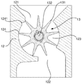
- the system further comprises a meter housing 12 , which includes a metering rotor 13 which is rotatable in the meter housing 12 .
- the metering rotor 13 can be driven by a drive unit, such as an electric or hydraulic motor (not shown).
- the metering rotor 13 can be driven directly by the motor or indirectly, for example via a transmission which can comprise gears, belts or friction wheels.
- the meter housing 12 has an inlet 121 at its upper portion and an outlet 122 at its lower portion.
- the inlet 121 connects to a lower portion of the material container 10 , so that material contained in this can be fed to the meter housing 12 , at least partly using gravitation. Additional feeding can possibly be provided using an agitator, a feed screw or a fluidized bed.
- the meter housing 12 includes a meter space 123 , which can have a generally cylindrical form.
- the meter space 123 has a cylindrical limit surface 124 , whose radius is approximately equal in size to, or somewhat smaller than, a radius of the metering rotor 13 .
- the radial outer portion of the wing blades 131 of the metering rotor can thus bear upon the cylindrical limit surface 124 .
- the bearing can be such that the wing blades 131 are pre-tensioned against the cylindrical limit surface 124 . Therefore, the wing blades, as a result of the friction between the wing blades and the cylindrical limit surface 124 , can bend out a little while the metering rotor 13 rotates in the meter space 123 .
- the meter space 123 can also have axial limit surfaces, of which at least one can have a bushing for an axle around which the metering rotor 13 is rotatable.
- This axle can be a drive axle which, as described above, can be connected to the drive unit.
- an axial limit surface can comprise a bushing and/or bearing for the axle.
- the metering rotor 13 can have a free end in the meter housing, i.e. no support in the radial direction in the event of an axially opposite portion relative to the drive axle.
- an axle bushing for a drive axle can be provided at one of the axial ends of the metering rotor 13 , while at its other axial end a support in the form of an integrated part of an axial limit surface is provided.
- the meter space 123 can have an axial length which is equal in size to, or somewhat smaller than, an axial length of the metering rotor 13 .
- the axial outer portions of the wing blades 131 of the metering rotor can thus bear against at least the one axial limit surface.
- the bearing can be such that the wing blades 131 are pre-tensioned against the axial limit surface 124 . Therefore, the wing blades, as a result of the friction between the wing blades and the axial limit surface, can bend out a little while the metering rotor 13 rotates in the meter space 123 .
- the metering housing 12 has an outlet 122 , which connects to a channel, so that material fed by the metering rotor 13 is introduced into the channel 14 via a channel inlet 141 .
- a pump or a fan 15 can be connected to the channel to provide an air stream in the channel 14 .
- the material can be introduced into the channel, so that an air stream mixed with material is achieved.
- the channel 14 can lead the material directly to one or several feed-out parts, for example furrow openers 16 a , 16 b , 16 c or fertilizer openers.
- a distributor 17 can be arranged for distributing the air stream mixed with material to the furrow openers 16 a , 16 b , 16 c .
- Such distributors are known from, for example, WO2015112086A1.
- one or more singulating devices 18 a , 18 b , 18 c can be arranged to ensure a more even flow of material to the furrow openers 16 a , 16 b , 16 c .
- Such singulating devices are known from, for example, WO2015069179A1.
- the metering rotor 13 can comprise a rotor core 132 and a plurality of rotor blades 131 .
- the rotor core 132 can be made of a relatively stiff material, such as metal or polymer. In the latter case, the rotor core can be made of a construction plastic with a relatively high stiffness.
- the rotor core 132 can be integrated with a motor shaft, i.e. permanently connected to the motor shaft or made in one piece with the motor shaft. Alternatively, the rotor core 132 can be a separate part, which is connected to a motor shaft in such a manner that torque from the motor is transferable to the metering rotor 13 .
- the rotor blades 131 can be made of polymer material with a lower stiffness than the material that the rotor core is made of.
- the rotor blades can be made of an elastic material, such as a rubber elastic material, for example polyurethane, rubber, thermoplastic elastomer or similar.
- the rotor blades 131 can also be made of a material which is softer than the material that the limitation walls 124 of the meter space are made of.
- the rotor blades 131 can be made in one piece of material, which can surround and enclose the core 132 .
- FIG. 2 shows a first embodiment of a meter housing, where one of the walls that define the meter space 123 , specifically a cylinder sector shaped wall 124 , has been provided with a recessed groove 1241 in the wall.
- the groove 1241 can extend across substantially the full axial length of the meter space 123 .
- the groove can have a depth corresponding to 0.1-20% of the radius of curvature of the wall 124 , preferably 0.5-15%, 1-15%, 5-15%, 7-13% or around 10%.
- the groove can have a width, along the tangential direction of the wall 124 , which can be about 1°-30°, 5°-25°, 10°-20° or about 15°.
- the groove can have straight or curved walls.
- the groove can have a couple of straight walls, which at the bottom of the groove form an angle with each other.
- the groove can have a substantially cylinder sector shaped cross-section.
- FIG. 3 shows a second embodiment of a meter housing, where one of the walls that define the meter space 123 , specifically a cylinder sector shaped wall 124 ′, has been provided with a ridge 1241 ′ projecting from the wall.
- the ridge 1241 can extend across substantially the full axial length of the meter space 123 .
- the ridge can have a height corresponding to 0.1-20% of the radius of curvature of the wall 124 ′, preferably 0.5-15%, 1-15%, 5-15%, 7-13% or around 10%.
- the ridge can have a width, along the tangential direction of the wall 124 , which can be about 1°-30°, 5°-25°, 10°-20° or about 15°.
- the ridge can have straight or curved walls.
- the ridge can have a couple of straight walls, which at the top of the ridge form an angle with each other.
- the ridge can have a substantially cylinder sector shaped cross-section.
- two, three or more ridges can be provided.
- such ridges are substantially parallel to each other.
- one or more grooves 1241 can be combined with one or more ridges 1241 ′.
- FIG. 4 shows an embodiment according to the illustration in FIG. 2 , with the exception that here there are two grooves 1241 a , 1241 b instead, which are located adjacent each other and run in parallel to each other, within an angle amounting to less than 10°, preferably less than 5° or less than 3° around the center of the wall 124 .
Abstract
Description
Claims (17)
Applications Claiming Priority (4)
| Application Number | Priority Date | Filing Date | Title |
|---|---|---|---|
| SE1551290A SE541232C2 (en) | 2015-10-08 | 2015-10-08 | Feeder housing for feeding granular or powdery material, feeding system, agricultural implements including such feeding system and method for feeding granular or powdery material |
| SE1551290 | 2015-10-08 | ||
| SE1551290-8 | 2015-10-08 | ||
| PCT/SE2016/050960 WO2017061941A1 (en) | 2015-10-08 | 2016-10-06 | Meter housing for feeding granular or powdered material, meter system, agricultural implement comprising such meter system and method for feeding granular or powdered material |
Publications (2)
| Publication Number | Publication Date |
|---|---|
| US20180310470A1 US20180310470A1 (en) | 2018-11-01 |
| US10561058B2 true US10561058B2 (en) | 2020-02-18 |
Family
ID=57256391
Family Applications (1)
| Application Number | Title | Priority Date | Filing Date |
|---|---|---|---|
| US15/766,482 Active 2036-12-20 US10561058B2 (en) | 2015-10-08 | 2016-10-06 | Meter housing for feeding granular or powdered material, meter system, agricultural implement comprising such meter system and method for feeding granular or powdered material |
Country Status (5)
| Country | Link |
|---|---|
| US (1) | US10561058B2 (en) |
| EP (1) | EP3358930B1 (en) |
| CA (1) | CA3001280C (en) |
| SE (1) | SE541232C2 (en) |
| WO (1) | WO2017061941A1 (en) |
Cited By (1)
| Publication number | Priority date | Publication date | Assignee | Title |
|---|---|---|---|---|
| US11656113B2 (en) * | 2019-07-19 | 2023-05-23 | Agra Industries, Inc. | Bulk material metering system |
Families Citing this family (10)
| Publication number | Priority date | Publication date | Assignee | Title |
|---|---|---|---|---|
| CN107455404B (en) * | 2017-07-31 | 2023-04-18 | 李亚军 | Full-automatic steamed bun making system and making method |
| US20210060574A1 (en) * | 2017-09-05 | 2021-03-04 | Mastek Limited | Macerator |
| CN108633358A (en) * | 2018-05-31 | 2018-10-12 | 贵州省福轩实业发展有限公司 | A kind of fertilizing equipment |
| US10757857B2 (en) | 2019-02-01 | 2020-09-01 | Cnh Industrial Canada, Ltd. | Meter roller insert system |
| US10736264B1 (en) | 2019-02-01 | 2020-08-11 | Cnh Industrial Canada, Ltd. | Modular meter roller shaft system |
| US10750665B1 (en) | 2019-02-01 | 2020-08-25 | Cnh Industrial Canada, Ltd. | Meter roller system |
| CN110480430A (en) * | 2019-08-19 | 2019-11-22 | 江门建滔高科技有限公司 | A kind of pcb plate special-purpose milling cutter centreless grinding feed appliance |
| KR102433119B1 (en) * | 2020-05-25 | 2022-08-16 | 이순재 | Apparatus for spreading pellet type fertilizer |
| CN112136394B (en) * | 2020-08-28 | 2022-05-27 | 安徽科技学院 | Fertilizing device and fertilizing process for corn cultivation |
| CN112374194A (en) * | 2020-11-24 | 2021-02-19 | 彭秀芳 | Feeding device for solving problems of flour adhesion on inner wall of material pipe and incapability of quantitative discharging |
Citations (46)
| Publication number | Priority date | Publication date | Assignee | Title |
|---|---|---|---|---|
| DE74845C (en) | K. NAUMANN, Hauptmann z. D., in Schlettau, Sachsen | Rotary seed drill | ||
| US46821A (en) * | 1865-03-14 | Improvement in grain-drills | ||
| US111726A (en) * | 1871-02-14 | Improvement in seed-sowers | ||
| US533255A (en) * | 1895-01-29 | Grain-meter | ||
| US647965A (en) * | 1899-06-02 | 1900-04-24 | Al H Herron | Dispensing and measuring apparatus. |
| DE420826C (en) | 1925-10-31 | Otto Merker | Seed machine with seed roller | |
| US2022631A (en) * | 1934-05-22 | 1935-11-26 | Service Station Equipment Comp | Fluid meter |
| US2262231A (en) * | 1939-09-05 | 1941-11-11 | Guibert | Liquid metering device |
| US2367311A (en) * | 1942-04-30 | 1945-01-16 | Continental Gin Co | Vacuum feeder |
| US2408285A (en) * | 1943-07-15 | 1946-09-24 | Hydraulic Dev Corp Inc | Feeding device for injection or extrusion machines |
| US2636479A (en) * | 1950-05-29 | 1953-04-28 | Frederic C Ripley Sr | Flowmeter |
| US2754995A (en) * | 1954-03-12 | 1956-07-17 | Howard A Switzer | Batching mechanism |
| US2853978A (en) * | 1956-03-05 | 1958-09-30 | Elmer D Smyser | Improved fluid motor |
| GB860235A (en) | 1956-05-11 | 1961-02-01 | Massey Ferguson Ltd | Improvements in and relating to seed sowing appliances |
| US3048132A (en) * | 1959-10-12 | 1962-08-07 | John F Morgan | Seed pellet dispenser and planter |
| US3072301A (en) * | 1959-04-03 | 1963-01-08 | Richardson Corp | Rotary feeder for bulk material |
| US3225661A (en) * | 1964-03-10 | 1965-12-28 | Smyser Fluid Motors | Rotary fluid motors |
| US3245386A (en) * | 1962-10-29 | 1966-04-12 | Curtiss Wright Corp | Seal lubrication for rotary engines |
| US3268266A (en) * | 1964-03-26 | 1966-08-23 | Rex Chainbelt Inc | Pneumatic conveyor system and method |
| US3568893A (en) * | 1969-06-09 | 1971-03-09 | Henry Becker | Dispenser |
| US3572555A (en) * | 1969-05-27 | 1971-03-30 | Ibm | Xerographic toner dispenser |
| US3895745A (en) | 1974-02-25 | 1975-07-22 | Johns Manville | Rotary valve having an improved air seal |
| US3922755A (en) * | 1974-12-03 | 1975-12-02 | Righele Giovanni | Rotary pump for feeding a continuous sausage-making machine |
| FR2294622A2 (en) | 1973-07-18 | 1976-07-16 | Audubert Leon | Seed and granular fertiliser distributor - with flow rate from hopper varied by moving one of pair of sleeves |
| US3982672A (en) * | 1974-06-14 | 1976-09-28 | Horstine Farmery Ltd | Applicators of granular materials |
| US4179043A (en) * | 1978-01-03 | 1979-12-18 | Koppers Company, Inc. | Rotary valve apparatus |
| US4180188A (en) * | 1975-11-18 | 1979-12-25 | Kokkoman Shoyu Co., Ltd. | Sealing structure for rotary valves |
| US4231495A (en) | 1978-02-23 | 1980-11-04 | Rader Companies, Inc. | Rotary feeder for pneumatic conveying line |
| US4480948A (en) * | 1981-07-24 | 1984-11-06 | Amazonen-Werke H. Dreyer Gmbh & Co. Kg | Machine for applying pellets and powder |
| US4522340A (en) * | 1983-07-01 | 1985-06-11 | Gandy Company | Granular material applicator with speed compensator |
| DE3432316A1 (en) | 1984-09-03 | 1986-03-13 | Hoechst Ag, 6230 Frankfurt | Rotary feeder |
| US4602727A (en) * | 1984-05-15 | 1986-07-29 | Wm. W. Meyer & Sons, Inc. | Rotary feeder system |
| DE3630425C1 (en) | 1986-09-06 | 1988-03-31 | Konrad Hendlmeier | Device for the singular or volumetric discharge of granular materials from granulate spreaders |
| US4811864A (en) * | 1987-08-03 | 1989-03-14 | Charles Balmer | Cleaning arrangement for a roller metering device |
| US5314090A (en) * | 1992-03-23 | 1994-05-24 | Terronics Development Corporation | Material feeder |
| US5324143A (en) | 1993-01-28 | 1994-06-28 | Sanders Kenneth L | Pneumatic grain conveyor and related method |
| WO1998012512A1 (en) | 1996-09-20 | 1998-03-26 | Väderstad-Verken Ab | Dosing feeder |
| WO2004015378A1 (en) | 2002-07-05 | 2004-02-19 | Gaspardo Seminatrici S.P.A. | A volumetric metering device for the metered delivery of granular and powdery materials, particularly for machines for distributing the said materials |
| US20080190964A1 (en) * | 2007-02-08 | 2008-08-14 | Ben Shlomo Tal E | Dry goods dispenser and dispensing mechanism |
| WO2008150241A1 (en) | 2007-06-06 | 2008-12-11 | Väderstad-Verken Aktiebolag | Rotor for an outfeed house at a sowing machine |
| US20100307395A1 (en) * | 2009-06-09 | 2010-12-09 | Snipes Terry L | Volumetric metering system with sectional shut-off |
| US20110049198A1 (en) * | 2009-08-26 | 2011-03-03 | Battelle Energy Alliance, Llc | Rotary feeders, rotor assemblies for rotary feeders and related methods |
| DE102011010619A1 (en) | 2011-02-08 | 2012-08-09 | Köckerling GmbH & Co. KG | Pneumatic dosing device for promoting granulated mineral fertilizer, has several dividing walls that are laterally formed on the support shaft and are not made of electrical conductive material |
| WO2013180619A1 (en) | 2012-05-31 | 2013-12-05 | Väderstad-Verken Ab | Agricultural implement and method for feeding granular material |
| WO2015069179A1 (en) | 2013-11-07 | 2015-05-14 | Väderstad-Verken Ab | Device for singulating granules, agricultural implement comprising such device and method of singulating granules |
| WO2015112086A1 (en) | 2014-01-27 | 2015-07-30 | Väderstad-Verken Ab | Device for monitoring feeding of granules, feeding device for such granules and method of installation of such monitoring device |
-
2015
- 2015-10-08 SE SE1551290A patent/SE541232C2/en unknown
-
2016
- 2016-10-06 EP EP16794081.6A patent/EP3358930B1/en active Active
- 2016-10-06 US US15/766,482 patent/US10561058B2/en active Active
- 2016-10-06 CA CA3001280A patent/CA3001280C/en active Active
- 2016-10-06 WO PCT/SE2016/050960 patent/WO2017061941A1/en active Application Filing
Patent Citations (47)
| Publication number | Priority date | Publication date | Assignee | Title |
|---|---|---|---|---|
| DE74845C (en) | K. NAUMANN, Hauptmann z. D., in Schlettau, Sachsen | Rotary seed drill | ||
| US46821A (en) * | 1865-03-14 | Improvement in grain-drills | ||
| US111726A (en) * | 1871-02-14 | Improvement in seed-sowers | ||
| US533255A (en) * | 1895-01-29 | Grain-meter | ||
| DE420826C (en) | 1925-10-31 | Otto Merker | Seed machine with seed roller | |
| US647965A (en) * | 1899-06-02 | 1900-04-24 | Al H Herron | Dispensing and measuring apparatus. |
| US2022631A (en) * | 1934-05-22 | 1935-11-26 | Service Station Equipment Comp | Fluid meter |
| US2262231A (en) * | 1939-09-05 | 1941-11-11 | Guibert | Liquid metering device |
| US2367311A (en) * | 1942-04-30 | 1945-01-16 | Continental Gin Co | Vacuum feeder |
| US2408285A (en) * | 1943-07-15 | 1946-09-24 | Hydraulic Dev Corp Inc | Feeding device for injection or extrusion machines |
| US2636479A (en) * | 1950-05-29 | 1953-04-28 | Frederic C Ripley Sr | Flowmeter |
| US2754995A (en) * | 1954-03-12 | 1956-07-17 | Howard A Switzer | Batching mechanism |
| US2853978A (en) * | 1956-03-05 | 1958-09-30 | Elmer D Smyser | Improved fluid motor |
| GB860235A (en) | 1956-05-11 | 1961-02-01 | Massey Ferguson Ltd | Improvements in and relating to seed sowing appliances |
| US3072301A (en) * | 1959-04-03 | 1963-01-08 | Richardson Corp | Rotary feeder for bulk material |
| US3048132A (en) * | 1959-10-12 | 1962-08-07 | John F Morgan | Seed pellet dispenser and planter |
| US3245386A (en) * | 1962-10-29 | 1966-04-12 | Curtiss Wright Corp | Seal lubrication for rotary engines |
| US3225661A (en) * | 1964-03-10 | 1965-12-28 | Smyser Fluid Motors | Rotary fluid motors |
| US3268266A (en) * | 1964-03-26 | 1966-08-23 | Rex Chainbelt Inc | Pneumatic conveyor system and method |
| US3572555A (en) * | 1969-05-27 | 1971-03-30 | Ibm | Xerographic toner dispenser |
| US3568893A (en) * | 1969-06-09 | 1971-03-09 | Henry Becker | Dispenser |
| FR2294622A2 (en) | 1973-07-18 | 1976-07-16 | Audubert Leon | Seed and granular fertiliser distributor - with flow rate from hopper varied by moving one of pair of sleeves |
| US3895745A (en) | 1974-02-25 | 1975-07-22 | Johns Manville | Rotary valve having an improved air seal |
| US3982672A (en) * | 1974-06-14 | 1976-09-28 | Horstine Farmery Ltd | Applicators of granular materials |
| US3922755A (en) * | 1974-12-03 | 1975-12-02 | Righele Giovanni | Rotary pump for feeding a continuous sausage-making machine |
| US4180188A (en) * | 1975-11-18 | 1979-12-25 | Kokkoman Shoyu Co., Ltd. | Sealing structure for rotary valves |
| US4179043A (en) * | 1978-01-03 | 1979-12-18 | Koppers Company, Inc. | Rotary valve apparatus |
| US4231495A (en) | 1978-02-23 | 1980-11-04 | Rader Companies, Inc. | Rotary feeder for pneumatic conveying line |
| US4480948A (en) * | 1981-07-24 | 1984-11-06 | Amazonen-Werke H. Dreyer Gmbh & Co. Kg | Machine for applying pellets and powder |
| US4522340A (en) * | 1983-07-01 | 1985-06-11 | Gandy Company | Granular material applicator with speed compensator |
| US4602727A (en) * | 1984-05-15 | 1986-07-29 | Wm. W. Meyer & Sons, Inc. | Rotary feeder system |
| DE3432316A1 (en) | 1984-09-03 | 1986-03-13 | Hoechst Ag, 6230 Frankfurt | Rotary feeder |
| DE3630425C1 (en) | 1986-09-06 | 1988-03-31 | Konrad Hendlmeier | Device for the singular or volumetric discharge of granular materials from granulate spreaders |
| US4811864A (en) * | 1987-08-03 | 1989-03-14 | Charles Balmer | Cleaning arrangement for a roller metering device |
| US5314090A (en) * | 1992-03-23 | 1994-05-24 | Terronics Development Corporation | Material feeder |
| US5324143A (en) | 1993-01-28 | 1994-06-28 | Sanders Kenneth L | Pneumatic grain conveyor and related method |
| WO1998012512A1 (en) | 1996-09-20 | 1998-03-26 | Väderstad-Verken Ab | Dosing feeder |
| WO2004015378A1 (en) | 2002-07-05 | 2004-02-19 | Gaspardo Seminatrici S.P.A. | A volumetric metering device for the metered delivery of granular and powdery materials, particularly for machines for distributing the said materials |
| US20080190964A1 (en) * | 2007-02-08 | 2008-08-14 | Ben Shlomo Tal E | Dry goods dispenser and dispensing mechanism |
| WO2008150241A1 (en) | 2007-06-06 | 2008-12-11 | Väderstad-Verken Aktiebolag | Rotor for an outfeed house at a sowing machine |
| US20100307395A1 (en) * | 2009-06-09 | 2010-12-09 | Snipes Terry L | Volumetric metering system with sectional shut-off |
| US20110049198A1 (en) * | 2009-08-26 | 2011-03-03 | Battelle Energy Alliance, Llc | Rotary feeders, rotor assemblies for rotary feeders and related methods |
| DE102011010619A1 (en) | 2011-02-08 | 2012-08-09 | Köckerling GmbH & Co. KG | Pneumatic dosing device for promoting granulated mineral fertilizer, has several dividing walls that are laterally formed on the support shaft and are not made of electrical conductive material |
| WO2013180619A1 (en) | 2012-05-31 | 2013-12-05 | Väderstad-Verken Ab | Agricultural implement and method for feeding granular material |
| US20150189827A1 (en) * | 2012-05-31 | 2015-07-09 | Vaderstad-Verken Ab | Agricultural Implement and Method for Feeding Granular Material |
| WO2015069179A1 (en) | 2013-11-07 | 2015-05-14 | Väderstad-Verken Ab | Device for singulating granules, agricultural implement comprising such device and method of singulating granules |
| WO2015112086A1 (en) | 2014-01-27 | 2015-07-30 | Väderstad-Verken Ab | Device for monitoring feeding of granules, feeding device for such granules and method of installation of such monitoring device |
Cited By (1)
| Publication number | Priority date | Publication date | Assignee | Title |
|---|---|---|---|---|
| US11656113B2 (en) * | 2019-07-19 | 2023-05-23 | Agra Industries, Inc. | Bulk material metering system |
Also Published As
| Publication number | Publication date |
|---|---|
| EP3358930B1 (en) | 2019-09-25 |
| CA3001280A1 (en) | 2017-04-13 |
| SE1551290A1 (en) | 2017-04-09 |
| US20180310470A1 (en) | 2018-11-01 |
| WO2017061941A1 (en) | 2017-04-13 |
| EP3358930A1 (en) | 2018-08-15 |
| SE541232C2 (en) | 2019-05-07 |
| CA3001280C (en) | 2024-02-27 |
Similar Documents
| Publication | Publication Date | Title |
|---|---|---|
| US10561058B2 (en) | Meter housing for feeding granular or powdered material, meter system, agricultural implement comprising such meter system and method for feeding granular or powdered material | |
| US10798871B2 (en) | Rotor assembly, method, feeder device and agricultural implement for feeding granular or powder material | |
| US9693499B2 (en) | Sealing gasket and seed housing for a seeder and seeder comprising such a seed housing | |
| US9137941B2 (en) | Row unit for a planter, planter and method for planting | |
| WO2017061942A1 (en) | Metering rotor for metering granular or powdered material in an agricultural implement, meter system and method for feeding granular or powdered material | |
| US20190230847A1 (en) | System for leveling particulate material | |
| US9282691B2 (en) | Air seed meter disc with flow directing pockets | |
| CA3093258C (en) | Ringed meter rollers and slide cutoff system | |
| JP4809686B2 (en) | Feeding device | |
| CN100414265C (en) | A volumetric metering device for the metered delivery of granular and powdery materials, particularly for machines for distributing the said materials | |
| AU2007201262A1 (en) | Dispenser | |
| US20120186505A1 (en) | Seed singulator housing and agricultural machine equipped with it | |
| US20160120109A1 (en) | Meter roller for an agricultural metering system | |
| EP1915895A2 (en) | Dispenser for dividing a main flow of a fluid into a number of partial fluids | |
| CN101496468A (en) | Seed-mixing device of circular tube air-suction seed metering device | |
| US324833A (en) | Guano-distributer | |
| US847290A (en) | End-gate seeding-machine. | |
| US682963A (en) | Cotton-seed planter and fertilizer-distributer. | |
| AU1004502A (en) | Dispenser |
Legal Events
| Date | Code | Title | Description |
|---|---|---|---|
| AS | Assignment |
Owner name: VADERSTAD HOLDING AB, SWEDEN Free format text: ASSIGNMENT OF ASSIGNORS INTEREST;ASSIGNOR:GILSTRING, GERT;REEL/FRAME:045459/0475 Effective date: 20180405 |
|
| FEPP | Fee payment procedure |
Free format text: ENTITY STATUS SET TO UNDISCOUNTED (ORIGINAL EVENT CODE: BIG.); ENTITY STATUS OF PATENT OWNER: LARGE ENTITY |
|
| STPP | Information on status: patent application and granting procedure in general |
Free format text: DOCKETED NEW CASE - READY FOR EXAMINATION |
|
| STPP | Information on status: patent application and granting procedure in general |
Free format text: NON FINAL ACTION MAILED |
|
| STPP | Information on status: patent application and granting procedure in general |
Free format text: NOTICE OF ALLOWANCE MAILED -- APPLICATION RECEIVED IN OFFICE OF PUBLICATIONS |
|
| STPP | Information on status: patent application and granting procedure in general |
Free format text: PUBLICATIONS -- ISSUE FEE PAYMENT RECEIVED |
|
| STCF | Information on status: patent grant |
Free format text: PATENTED CASE |
|
| MAFP | Maintenance fee payment |
Free format text: PAYMENT OF MAINTENANCE FEE, 4TH YEAR, LARGE ENTITY (ORIGINAL EVENT CODE: M1551); ENTITY STATUS OF PATENT OWNER: LARGE ENTITY Year of fee payment: 4 |