US10560359B2 - Method and device for reducing multicast flow joint latency - Google Patents
Method and device for reducing multicast flow joint latency Download PDFInfo
- Publication number
- US10560359B2 US10560359B2 US15/389,960 US201615389960A US10560359B2 US 10560359 B2 US10560359 B2 US 10560359B2 US 201615389960 A US201615389960 A US 201615389960A US 10560359 B2 US10560359 B2 US 10560359B2
- Authority
- US
- United States
- Prior art keywords
- node
- multicast flow
- multicast
- flow
- link
- Prior art date
- Legal status (The legal status is an assumption and is not a legal conclusion. Google has not performed a legal analysis and makes no representation as to the accuracy of the status listed.)
- Expired - Fee Related, expires
Links
- 238000000034 method Methods 0.000 title claims abstract description 107
- 230000004044 response Effects 0.000 claims description 46
- 230000005540 biological transmission Effects 0.000 claims description 3
- 230000005055 memory storage Effects 0.000 claims 2
- 238000012913 prioritisation Methods 0.000 description 38
- 238000009826 distribution Methods 0.000 description 22
- 238000010586 diagram Methods 0.000 description 12
- 238000005304 joining Methods 0.000 description 9
- 238000004519 manufacturing process Methods 0.000 description 9
- 230000008859 change Effects 0.000 description 7
- 238000012544 monitoring process Methods 0.000 description 7
- 238000003860 storage Methods 0.000 description 7
- 238000009966 trimming Methods 0.000 description 7
- 238000011144 upstream manufacturing Methods 0.000 description 5
- 230000006870 function Effects 0.000 description 4
- 230000008569 process Effects 0.000 description 4
- 238000004891 communication Methods 0.000 description 3
- 238000007726 management method Methods 0.000 description 3
- 235000008694 Humulus lupulus Nutrition 0.000 description 2
- 244000141353 Prunus domestica Species 0.000 description 2
- 230000001419 dependent effect Effects 0.000 description 2
- 230000007246 mechanism Effects 0.000 description 2
- 238000013138 pruning Methods 0.000 description 2
- 239000007787 solid Substances 0.000 description 2
- 230000008901 benefit Effects 0.000 description 1
- 230000000694 effects Effects 0.000 description 1
- 230000003287 optical effect Effects 0.000 description 1
- 230000009467 reduction Effects 0.000 description 1
Images


Classifications
-
- H—ELECTRICITY
- H04—ELECTRIC COMMUNICATION TECHNIQUE
- H04L—TRANSMISSION OF DIGITAL INFORMATION, e.g. TELEGRAPHIC COMMUNICATION
- H04L43/00—Arrangements for monitoring or testing data switching networks
- H04L43/08—Monitoring or testing based on specific metrics, e.g. QoS, energy consumption or environmental parameters
- H04L43/0876—Network utilisation, e.g. volume of load or congestion level
- H04L43/0882—Utilisation of link capacity
-
- H—ELECTRICITY
- H04—ELECTRIC COMMUNICATION TECHNIQUE
- H04L—TRANSMISSION OF DIGITAL INFORMATION, e.g. TELEGRAPHIC COMMUNICATION
- H04L12/00—Data switching networks
- H04L12/02—Details
- H04L12/16—Arrangements for providing special services to substations
- H04L12/18—Arrangements for providing special services to substations for broadcast or conference, e.g. multicast
- H04L12/185—Arrangements for providing special services to substations for broadcast or conference, e.g. multicast with management of multicast group membership
-
- H—ELECTRICITY
- H04—ELECTRIC COMMUNICATION TECHNIQUE
- H04L—TRANSMISSION OF DIGITAL INFORMATION, e.g. TELEGRAPHIC COMMUNICATION
- H04L45/00—Routing or path finding of packets in data switching networks
- H04L45/12—Shortest path evaluation
- H04L45/125—Shortest path evaluation based on throughput or bandwidth
-
- H—ELECTRICITY
- H04—ELECTRIC COMMUNICATION TECHNIQUE
- H04L—TRANSMISSION OF DIGITAL INFORMATION, e.g. TELEGRAPHIC COMMUNICATION
- H04L45/00—Routing or path finding of packets in data switching networks
- H04L45/16—Multipoint routing
-
- H—ELECTRICITY
- H04—ELECTRIC COMMUNICATION TECHNIQUE
- H04L—TRANSMISSION OF DIGITAL INFORMATION, e.g. TELEGRAPHIC COMMUNICATION
- H04L45/00—Routing or path finding of packets in data switching networks
- H04L45/302—Route determination based on requested QoS
-
- H—ELECTRICITY
- H04—ELECTRIC COMMUNICATION TECHNIQUE
- H04L—TRANSMISSION OF DIGITAL INFORMATION, e.g. TELEGRAPHIC COMMUNICATION
- H04L45/00—Routing or path finding of packets in data switching networks
- H04L45/48—Routing tree calculation
-
- H—ELECTRICITY
- H04—ELECTRIC COMMUNICATION TECHNIQUE
- H04L—TRANSMISSION OF DIGITAL INFORMATION, e.g. TELEGRAPHIC COMMUNICATION
- H04L47/00—Traffic control in data switching networks
- H04L47/10—Flow control; Congestion control
- H04L47/15—Flow control; Congestion control in relation to multipoint traffic
Definitions
- the present disclosure generally relates to network routing, and in particular, to systems, methods, and devices for reducing multicast flow join latency.
- IP Internet Protocol
- IGMP Internet Group Management Protocol
- any device in an IP system is able to submit an IGMP join request to start receiving these flows, which potentially enables malicious devices to disrupt the system or steal unauthorized media content.
- FIG. 1 is a block diagram of an example multicast network environment in accordance with some implementations.
- FIGS. 2A-2G illustrate block diagrams of an example multicast flow traversing an example multicast network in accordance with various implementations.
- FIGS. 3A-3F illustrate block diagrams of an example multicast flow traversing an example improved multicast network in accordance with various implementations.
- FIGS. 4A-4F illustrate block diagrams of example multicast flows traversing the example improved multicast network in accordance with various implementations.
- FIG. 5 is a flowchart representation of a method of pre-routing multicast flows within a network to reduce joining latency in accordance with some implementations.
- FIG. 6 is a flowchart representation of a method of pre-routing multicast flows within a network to reduce multicast flow join latency in accordance with some implementations.
- FIG. 7 is a flowchart representation of a method of routing a multicast flow in accordance with some implementations.
- FIG. 8 is a flowchart representation of a method of routing a multicast flow in accordance with some implementations.
- FIG. 9 is a block diagram of an example device in accordance with some implementations.
- a method includes: determining a first node as a current termination node of a first multicast flow; determining whether a link between the first node and a downstream next-hop node has available bandwidth to accommodate the first multicast flow, where the downstream next-hop node is not currently associated with the first multicast flow; and transmitting the first multicast flow to the downstream next-hop node according to a determination that the link between the first node and a downstream next-hop node has available bandwidth to accommodate the first multicast flow.
- the method is performed by a controller with one or more processors and non-transitory memory, where the controller is communicatively coupled to a plurality of network nodes in a network.
- a device includes one or more processors, a non-transitory memory, and one or more programs; the one or more programs are stored in the non-transitory memory and configured to be executed by the one or more processors and the one or more programs include instructions for performing or causing performance of any of the methods described herein.
- a non-transitory computer readable storage medium has stored therein instructions, which, when executed by one or more processors of a device, cause the device to perform or cause performance of any of the methods described herein.
- a device includes: one or more processors, a non-transitory memory, and means for performing or causing performance of any of the methods described herein.
- the host-driven nature of the Internet Group Management Protocol (IGMP) for multicast Internet Protocol (IP) flows causes intolerable latency for certain workflows such as live broadcast production and distribution.
- the various implementations disclosed herein reduce the number of hops to route a multicast flow to the destination, which in turn reduces the IGMP join latency.
- This reduction in the number of hops is accomplished by pre-routing multicast flows towards downstream edge(s) and holding the multicast flows there until requested by a destination.
- the pre-routing of a flow is accomplished amongst the nodes (e.g., switches, routers, and/or the like) of a network in parallel in order to further reduce overall setup time. This reduces the typical processing associated with routing the multicast flow from the source to the destination and significantly reduces the IGMP join latency.
- multiple IGMP join requests can be processed in parallel to further reduce IGMP join latency in large systems.
- this solution provides a mechanism to hold multicast flows at the downstream edge so that the multicast flows can be transmitted to destinations with very short latency.
- this solution can be leveraged to reduce the response time to IGMP join requests. This reduced latency is due to the fact that the multicast flow is already available at or near the edge which adds little to no multicast routing activity. Furthermore, unused, less used, and/or low priority flows can be evicted from the edge or held further upstream from the edge to reduce the associated bandwidth burden.
- a video switcher used for live broadcast production would benefit from reduced response times to IGMP requests.
- the industry standard for latency in live broadcast production is between 1 and 5 milliseconds, which is supported by existing serial-to-digital interface (SDI) systems.
- SDI serial-to-digital interface
- a small number of flows e.g., 10 to 20 flows on average
- the video switcher receives all the flows in the system (e.g., 100 to 200 flows), which uses a great number of network interfaces and consumes a significant amount of bandwidth. This drastically reduces the scale that the video switcher can support.
- a great number of SDI to IP gateways are deployed. As a result, hardware, software, and bandwidth costs are high due to the inability of the IP network to provide flows with low latency as a result of the current response time to IGMP requests.
- this solution holds multicast flows in the network switch as opposed to holding the flows in the video switcher, as is the case today. Instead, with this solution, multicast flows can be delivered to the video switcher on demand. This means that the video switcher can be significantly slimmer, have far fewer network interfaces, and far less bandwidth to operate. For example, instead of 120 network interfaces and ⁇ 360 Gbps bandwidth capacity (e.g., 120 high definition (HD) video flows with 3 Gbps per HD video flow) at the video switcher, the number of network interfaces at the video switcher may be reduced to 20 with a bandwidth capacity of ⁇ 60 Gbps (e.g., (e.g., 20 HD video flows with 3 Gbps per HD video flow). As such, in the case of live broadcast production, this solution saves bandwidth, cabling, and slims down the video switcher.
- ⁇ 360 Gbps bandwidth capacity e.g., 120 high definition (HD) video flows with 3 Gbps per HD video flow
- FIG. 1 is a block diagram of an example multicast network environment 100 in accordance with some implementations. While pertinent features are shown, those of ordinary skill in the art will appreciate from the present disclosure that various other features have not been illustrated for the sake of brevity and so as not to obscure more pertinent aspects of the example implementations disclosed herein. To that end, as a non-limiting example, the multicast network environment 100 includes a multicast source node 102 A, a multicast listener group 110 , a controller 120 , and one or more networks 130 .
- the one or more networks 130 correspond to one or more portions of the public Internet, one or more local area networks (LANs), one or more wide area networks (WANs), one or more metropolitan area networks (MANs), one or more personal area networks (PANs), and/or the like.
- LANs local area networks
- WANs wide area networks
- MANs metropolitan area networks
- PANs personal area networks
- the multicast source node 102 A is communicatively coupled with the one or more networks 130 via a gateway node 104 A.
- the multicast source node 102 A corresponds to a content server device or the like.
- destination node 112 A is communicatively coupled with the one or more networks 130 via a gateway node 104 B
- destination nodes 112 B and 112 C are communicatively coupled with the one or more networks 130 via a gateway node 104 C.
- the destination nodes 112 A, 112 B, and 112 C (sometimes collectively referred to herein as the “destination nodes 112 ”) correspond to media recording devices, multi-viewer devices, media editing devices, or content consumption devices such as desktop computers, tablet computers, mobile phones, personal digital assistants (PDAs), wearable computing devices, set-top boxes (STBs), over-the-top (OTT) boxes, home appliances, security systems, Internet of things (IoT) devices, or the like.
- the destination nodes 112 are client devices associated with end-users.
- the gateway nodes 104 A, 104 B, and 104 C (sometimes collectively referred to herein as the “gateway nodes 104 ”) correspond to gateway devices, routers, managed switches, unmanaged switches, hubs, bridges, access points, or a suitable combination thereof.
- the multicast source node 102 A provides an IP multicast flow (e.g., a media content stream, an emergency signal, etc.) associated with a multicast IP address to which any number of destination nodes can join or subscribe.
- the multicast flow includes a stream of multicast packets transmitted using the user datagram protocol (UDP) or the pragmatic general multicast (PGM) transport protocol.
- UDP user datagram protocol
- PGM pragmatic general multicast
- a multicast listener group 110 including destination nodes 112 A, 112 B, and 112 C, subscribes to the IP multicast flow provided by the multicast source node 102 A.
- the multicast listener group 110 includes an arbitrary number of destination nodes 112 .
- the destination node 112 A subscribes to the IP multicast flow provided by the multicast source node 102 A by transmitting an IGMP join request (e.g., for IPv4 networks) or a Multicast Listener Discovery (MLD) request (e.g., for IPv6 networks) to the gateway node 104 B specifying the multicast IP address of the IP multicast flow provided by the multicast source node 102 A.
- an IGMP join request e.g., for IPv4 networks
- MLD Multicast Listener Discovery
- the gateway node 104 B builds up a multicast distribution tree using a multicast routing protocol, such as the Multicast Source Discovery Protocol (MSDP), Protocol Independent Multicast-Sparse Mode (PIM-SM), or Protocol Independent Multicast-Dense Mode (PIM-DM), to determine the closest node associated with the IP multicast flow and subsequently route/transmit the IP multicast flow to the destination node 112 A.
- a multicast routing protocol such as the Multicast Source Discovery Protocol (MSDP), Protocol Independent Multicast-Sparse Mode (PIM-SM), or Protocol Independent Multicast-Dense Mode (PIM-DM)
- the controller 120 is configured to reduce the latency experienced by the destination nodes 112 between requesting to join the IP multicast flow and receiving the IP multicast flow.
- the controller 120 or one or more components thereof e.g., the pre-routing logic 126
- BW bandwidth
- the latency experienced by the destination nodes 112 between requesting to join the IP multicast flow and receiving the IP multicast flow is reduced because the IP multicast flows are pre-routed closer to the edge. See, for example, the description of FIGS. 3A-3F and 4A-4F for further detail regarding the controller 120 including the BW decision logic 122 , the prioritization logic 124 , and the pre-routing logic 126 .
- FIGS. 2A-2G illustrate block diagrams of an example multicast flow 210 traversing an example multicast network 200 in accordance with various implementations. While certain specific features are illustrated, those skilled in the art will appreciate from the present disclosure that various other features have not been illustrated for the sake of brevity, and so as not to obscure more pertinent aspects of the implementations disclosed herein.
- the multicast network 200 includes multicast (MC) source nodes 202 A and 202 B (sometimes collectively referred to herein as the “MC source nodes 202 ”), a network 205 including a plurality of MC nodes 206 A, 206 B, 206 C, 206 D, 206 E, 206 F, 206 G, and 206 H (sometimes collectively referred to herein as the “MC nodes 206 ”), and destination (dest) nodes 204 A, 204 B, 204 C, and 204 D (sometimes collectively referred to herein as the “destination nodes 204 ”).
- MC multicast
- the MC source nodes 202 correspond to any suitable combination of media content production and distribution devices such as content servers, cameras, microphones, video editing devices, and/or the like.
- the destination nodes 204 correspond to content consumption devices, media recording devices, multi-viewer devices, media editing devices, and/or the like.
- the MC nodes 206 correspond to switches, routers, hubs, servers, and/or the like. According to some implementations, those of ordinary skill in the art will appreciate from the present disclosure that the MC nodes 206 within the network 205 are communicatively coupled via an arbitrary topology and that various other topologies could also be implemented between the MC source nodes 202 and the destination nodes 204 .
- the MC source nodes 202 correspond to content serving devices or entities such as media servers or media distribution entities.
- the MC nodes 206 correspond to a multicast capable routers within a core or backbone network.
- the MC nodes 206 comprise a routed network segment, such as a collapsed backbone or routers, that employ the router-port group management protocol (RGMP).
- the destination nodes 204 correspond to content consuming devices or entities such as desktop computers, tablet computers, mobile phones, PDAs, wearable computing devices, STBs, OTT boxes, home appliances, security systems, IoT devices, or the like.
- the MC source node 202 A initiates a multicast flow 210 .
- the multicast flow 210 is associated with a particular IP address to which listeners are able to join or subscribe.
- the multicast flow 210 is transmitted to MC node 206 A (e.g., a source edge router or a gateway node associated with the MC source node 202 A).
- the destination node 204 A transmits a join request 220 to MC node 206 D (e.g., a source edge router or a gateway node associated with the destination node 204 A) to join or subscribe to the multicast flow 210 .
- the join request 220 is an IGMP join request that specifies the IP address associated with the multicast flow 210 .
- the join request 220 is an MLD join request that specifies the IP address associated with the multicast flow 210 .
- the MC node 206 D determines a closest node associated with the multicast flow 210 .
- the MC nodes 206 use MSDP, PIM-SM, or PIM-DM to build up a multicast distribution tree (e.g., source or shared trees) for the multicast flow 210 that includes a route 222 from the MC node 206 D to the closest node associated with the multicast flow 210 (e.g., the MC node 206 A).
- a multicast distribution tree e.g., source or shared trees
- the MC node 206 D first determines whether one of its reception (Rx) interfaces is receiving the multicast flow 210 , and then the MC node 206 D transmits PIM messages to MC nodes 206 C and 206 E to determine whether one of their Rx interfaces is receiving the multicast flow 210 .
- the MC routers continuing transmitting PIM messages to adjacent/linked routers to determine the closest node associated with the multicast flow 210 and to build up a multicast distribution tree in order to route the multicast flow 210 from the MC node 206 A to the destination node 204 A.
- the process of described above is repeated on each of the MC nodes between MC node 206 D and MC node 206 A and is done serially.
- the MC node 206 D processes the PIM message and then send PIM messages to the MC nodes 206 E and 206 C.
- MC nodes 206 E and 206 C After receiving these messages MC nodes 206 E and 206 C will process the PIM message, build internal multicast trees and forward them to the nearest MC nodes.
- processing these PIM messages in serial adds to the amount of time it takes to build the multicast tree across the network 205 and increases overall latency.
- the multicast flow 210 is routed to the destination node 204 A.
- the multicast flow 210 is routed down the multicast distribution tree using reverse path forwarding (RPF) to ensure a loop free route from the MC node 206 A to the destination node 204 A.
- RPF reverse path forwarding
- a non-trivial amount of time elapses between the join request 220 in FIG. 2B and the routing of the multicast flow 210 to the destination node 204 A in FIG. 2D due to the time involved in building the multicast distribution tree and routing the multicast flow 210 via RPF.
- the destination node 204 B transmits a join request 230 to MC node 206 E (e.g., a source edge router or a gateway node associated with the destination node 204 B) to join or subscribe to the multicast flow 210 .
- the join request 230 is an IGMP join request that specifies the IP address associated with the multicast flow 210 .
- the join request 230 is an MLD join request that specifies the IP address associated with the multicast flow 210 .
- the MC node 206 E determines a closest node associated with the multicast flow 210 .
- the MC nodes 206 use MSDP, PIM-SM, or PIM-DM to build up a multicast distribution tree (e.g., source or shared trees) for the multicast flow 210 that includes a route 232 from the MC node 206 E to the closest node associated with the multicast flow 210 (e.g., the MC node 206 D).
- a multicast distribution tree e.g., source or shared trees
- the multicast flow 210 is routed to the destination node 204 B via the tributary multicast flow 212 .
- the multicast flow 210 is routed down the multicast distribution tree using RPF to ensure a loop free route from the MC node 206 A to the destination nodes 204 A and 204 B.
- FIGS. 3A-3F illustrate block diagrams of an example multicast flow 310 traversing an example improved multicast network 300 in accordance with various implementations.
- the improved multicast network 300 is similar to and adapted from the multicast network environment 200 in FIGS. 2A-2G .
- FIGS. 2A-2G and FIGS. 3A-3F include similar reference numerals and only the differences will be discussed herein for the sake of brevity. While certain specific features are illustrated, those skilled in the art will appreciate from the present disclosure that various other features have not been illustrated for the sake of brevity, and so as not to obscure more pertinent aspects of the implementations disclosed herein.
- the improved multicast network 300 includes the MC source nodes 202 , the network 205 including the plurality of MC nodes 206 , the destination nodes 204 , and the controller 120 .
- the controller 120 is configured to reduce the latency experienced by the destination nodes 204 between requesting to join a respective multicast flow and receiving the respective multicast flow.
- the controller 120 is separate from and communicatively coupled with the MC nodes 206 within the network 205 .
- the controller 120 is a distributed device implemented amongst the MC nodes 206 within the network 205 .
- the controller 120 includes bandwidth (BW) decision logic 122 , prioritization logic 124 , and pre-routing logic 126 .
- BW bandwidth
- the BW decision logic 122 is configured to determines whether a link between a current terminal MC router and a downstream next hop MC router has available bandwidth to accommodate a multicast flow.
- the prioritization logic 124 is configured to determine priority values for two or more multicast flows when a link has sufficient BW to accommodate one of the two or more multicast flows.
- the pre-routing logic 126 is configured to transmit/route the multicast flow from the current terminal MC router to the downstream next hop MC router based on determinations by the BW decision logic 122 and/or the prioritization logic 124 .
- the MC source node 202 A initiates multicast flow 310 .
- the multicast flow 310 is associated with a particular IP address to which listeners are able to join or subscribe.
- the multicast flow 310 is transmitted to MC node 206 A (e.g., a source edge router or a gateway node associated with the MC source node 202 A).
- the controller 120 or one or more components thereof perform determinations 350 A and 350 B.
- the controller 120 or one or more components thereof determine whether link 212 A has available BW to accommodate the multicast flow 310 . If the link 212 A has available BW to accommodate the multicast flow 310 , the controller 120 or one or more components thereof (e.g., the pre-routing logic 126 ) transmit/route the multicast flow 310 to the MC node 206 B via a tributary multicast flow (e.g., the tributary multicast flow 312 in FIG. 3B ). If the link 212 A does not have available BW to accommodate the multicast flow 310 , the multicast flow 310 is maintained at the MC node 206 A and is not transmitted to the MC node 206 B.
- the controller 120 or one or more components thereof determine whether link 212 E has available BW to accommodate the multicast flow 310 . If the link 212 E has available BW to accommodate the multicast flow 310 , the controller 120 or one or more components thereof (e.g., the pre-routing logic 126 ) transmit/route the multicast flow 310 to the MC node 206 F via a tributary multicast flow (e.g., the tributary multicast flow 314 in FIG. 3B ). If the link 212 E does not have available BW to accommodate the multicast flow 310 , the multicast flow 310 is maintained at the MC node 206 A and is not transmitted to the MC node 206 F.
- a tributary multicast flow e.g., the tributary multicast flow 314 in FIG. 3B
- the controller 120 or one or more components thereof transmit/route the multicast flow 310 to the MC node 206 B via a tributary multicast flow 312 .
- the BW of the link 212 A is 100 Gbps
- the current reserved BW associated with the link 212 A is 75 Gbps.
- the available BW of the link 212 A is 25 Gbps.
- the BW of the multicast flow 310 is 10 Gbps.
- the link 212 A has sufficient BW to accommodate the multicast flow 310 because the available BW of the link 212 A is greater than the BW of the multicast flow 310 (e.g., 25 Gbps>10 Gbps).
- the available BW of a link is reduced by a predefined buffer BW (e.g., 20 Gbps) to account for BW reading inaccuracies, loss, delay, change in current BW demand, emergency BW for high priority flows, and/or the like.
- the controller 120 or one or more components thereof transmit/route the multicast flow 310 to the MC node 206 F via a tributary multicast flow 314 .
- the controller 120 or one or more components thereof perform a determinations 350 C to determine whether link 212 B has available BW to accommodate the tributary multicast flow 312 . If the link 212 B has available BW to accommodate the tributary multicast flow 312 , the controller 120 or one or more components thereof (e.g., the pre-routing logic 126 ) transmit/route the tributary multicast flow 312 to the MC node 206 C. If the link 212 B does not have available BW to accommodate the tributary multicast flow 312 , the tributary multicast flow 312 is maintained at the MC node 206 B and is not transmitted to the MC node 206 C.
- the controller 120 or one or more components thereof perform a determination 350 D to determine whether link 212 F has available BW to accommodate the tributary multicast flow 314 . If the link 212 F has available BW to accommodate the tributary multicast flow 314 , the controller 120 or one or more components thereof (e.g., the pre-routing logic 126 ) transmit/route the tributary multicast flow 314 to the MC node 206 G. If the link 212 F does not have available BW to accommodate the tributary multicast flow 314 , the tributary multicast flow 314 is maintained at the MC node 206 F and is not transmitted to the MC node 206 G.
- the controller 120 or one or more components thereof transmit/route the tributary multicast flow 312 to the MC node 206 C.
- the controller 120 or one or more components thereof maintain the tributary multicast flow 314 at the MC node 206 F.
- the controller 120 or one or more components thereof determine whether the tributary multicast flow 314 has a higher prioritization value than any other flow that was previously pre-routed to the MC node 206 G via the link 212 F.
- the controller 120 or one or more components thereof determines whether the one or more other flows with lower prioritization values are associated with a greater or equal amount of bandwidth as the tributary multicast flow 314 .
- the controller 120 or one or more components thereof maintain the tributary multicast flow 314 at the MC node 206 F.
- the controller 120 or one or more components thereof evict the one or more other flows from the MC node 206 G (e.g., the one or more other flows are no longer pre-routed to the MC node 206 G) and route the tributary multicast flow 314 to the MC node 206 G.
- the controller 120 or one or more components thereof maintain the tributary multicast flow 314 at the MC node 206 F.
- the controller 120 or one or more components thereof perform determinations 350 E and 350 F.
- the controller 120 or one or more components thereof determine whether link 212 C has BW to accommodate the tributary multicast flow 312 . If the link 212 A has available BW to accommodate the multicast flow 310 , the controller 120 or one or more components thereof (e.g., the pre-routing logic 126 ) transmit/route the tributary multicast flow 312 to the MC node 206 D. If the link 212 C does not have available BW to accommodate the tributary multicast flow 312 , the tributary multicast flow 312 is maintained at the MC node 206 C and is not transmitted to the MC node 206 D.
- the controller 120 or one or more components thereof determine whether link 212 H has available BW to accommodate the tributary multicast flow 312 . If the link 212 H has available BW to accommodate the tributary multicast flow 312 , the controller 120 or one or more components thereof (e.g., the pre-routing logic 126 ) transmit/route the tributary multicast flow 312 to the MC node 206 H. If the link 212 H does not have available BW to accommodate the tributary multicast flow 312 , the tributary multicast flow 312 is maintained at the MC node 206 C and is not transmitted to the MC node 206 H.
- the controller 120 or one or more components thereof determine whether link 212 H has available BW to accommodate the tributary multicast flow 312 . If the link 212 H has available BW to accommodate the tributary multicast flow 312 , the controller 120 or one or more components thereof (e.g., the pre-routing logic 126 ) transmit/route the
- the controller 120 or one or more components thereof route the tributary multicast flow 312 to the MC node 206 D.
- the controller 120 or one or more components thereof do not route the tributary multicast flow 312 to the MC node 206 H.
- the controller 120 or one or more components thereof cease to pre-route multicast flows once an edge node is reached (e.g., the MC node 206 D). In some implementations, once an edge node is reached, the controller 120 or one or more components thereof (e.g., the pre-routing logic 126 ) pre-route multicast flows to other edge nodes but no further downstream.
- the determinations 350 A, 350 B, 350 C, 350 D, 350 E, and 350 F are discussed sequentially.
- the pre-routing of the tributary flows 312 and 314 in the network 205 need not happen sequentially in various implementations.
- the controller 120 or one or more components thereof e.g., the BW decision logic 122 and pre-routing logic 126 ) have complete picture of the network 205 and available BW on the links 212 .
- the controller 120 or one or more components thereof determines how far each flow can be pre-routed within the network 205 and issues pre-routing commands to each of the MC nodes 206 in parallel in order to reduce overall setup time.
- the destination node 204 D transmits a join request 322 to MC node 206 G (e.g., a source edge router or a gateway node associated with the destination node 204 D) to join or subscribe to the multicast flow 310 .
- the join request 322 is an IGMP join request that specifies the IP address associated with the multicast flow 310 .
- the join request 322 is an MLD join request that specifies the IP address associated with the multicast flow 310 .
- the controller 120 or one or more components thereof determine how far the multicast flow 310 (or the tributary multicast flow 314 ) is pre-routed within the network 205 . In some implementations, the controller 120 or one or more components thereof compute a path from the MC source node 202 A to the destination node 204 D based on the closest MC node to which the multicast flow 310 is pre-routed (e.g., the MC node 206 F).
- the controller 120 or one or more components thereof evicts pre-routed flows from the MC nodes 206 in the computed path if any of the links in the computed path have insufficient BW to accommodate the multicast flow 310 (or the tributary multicast flow 314 ).
- the controller 120 or one or more components thereof send routing requests to the MC nodes 206 in the computed path (e.g., in parallel) to build a multicast distribution tree from the MC source node 202 A to the destination node 204 D (e.g., a multicast routing tree).
- the tributary multicast flow 314 is routed from the MC node 206 F through the MC node 206 G to the destination node 204 D.
- the multicast flow 310 (or the tributary multicast flow 314 ) is routed down the multicast distribution tree using reverse path forwarding (RPF) to ensure a loop free route.
- RPF reverse path forwarding
- the amount of time to route the multicast flow 310 to the destination node 204 D is less than if the multicast flow 310 were not pre-routed to the MC node 206 F.
- pre-routing the multicast flow 310 via the tributary multicast flow 314 reduces the amount of time between the join request 322 in FIG. 3D and routing of the multicast flow 310 to the destination node 204 D in FIG. 3E .
- the destination node 204 A transmits a join request 324 to MC node 206 D (e.g., a source edge router or a gateway node associated with the destination node 204 A) to join or subscribe to the multicast flow 310 .
- the join request 324 is an IGMP join request that specifies the IP address associated with the multicast flow 310 .
- the join request 324 is an MLD join request that specifies the IP address associated with the multicast flow 310 .
- the controller 120 or one or more components thereof determine how far the multicast flow 310 (or the tributary multicast flow 312 ) is pre-routed within the network 205 . In some implementations, the controller 120 or one or more components thereof compute a path from the MC source node 202 A to the destination node 204 A based on the closest MC node to which the multicast flow 310 is pre-routed (e.g., the MC node 206 D).
- the controller 120 or one or more components thereof evicts pre-routed flows from the MC nodes 206 in the computed path if any of the links in the computed path have insufficient BW to accommodate the multicast flow 310 (or the tributary multicast flow 312 ).
- the controller 120 or one or more components thereof send routing requests to the MC nodes 206 in the computed path (e.g., in parallel) to build a multicast distribution tree from the MC source node 202 A to the destination node 204 A (e.g., a multicast routing tree).
- the tributary multicast flow 312 is routed from the MC node 206 D to the destination node 204 A.
- the multicast flow 310 (or the tributary multicast flow 312 ) is routed down the multicast distribution tree using reverse path forwarding (RPF) to ensure a loop free route.
- RPF reverse path forwarding
- the amount of time to route the multicast flow 310 to the destination node 204 A is less than if the multicast flow 310 were not pre-routed to the MC node 206 D.
- pre-routing the multicast flow 310 via the tributary multicast flow 312 reduces the amount of time between the join request 324 in FIG. 3E and routing of the multicast flow 310 to the destination node 204 A in FIG. 3F .
- FIGS. 4A-4F illustrate block diagrams of example multicast flows 410 and 420 traversing the example improved multicast network 300 in accordance with various implementations.
- the block diagrams in FIGS. 4A-4F are similar to and adapted from the block diagrams in FIGS. 3A-3F .
- FIGS. 3A-3F and FIGS. 4A-4F include similar reference numerals and only the differences will be discussed herein for the sake of brevity.
- the MC source node 202 A initiates a multicast flow 410 .
- the multicast flow 410 is associated with a first IP address to which listeners are able to join or subscribe.
- the multicast flow 410 is transmitted to MC node 206 A (e.g., a source edge router or a gateway node associated with the MC source node 202 A).
- the MC source node 202 B initiates a multicast flow 420 .
- the multicast flow 420 is associated with a second IP address to which listeners are able to join or subscribe.
- the multicast flow 420 is transmitted to MC node 206 A (e.g., a source edge router or a gateway node associated with the MC source node 202 B).
- MC node 206 A e.g., a source edge router or a gateway node associated with the MC source node 202 B.
- the controller 120 or one or more components thereof perform determinations 450 A and 450 B.
- the controller 120 or one or more components thereof determine whether link 212 A has available bandwidth (BW) to accommodate both of the multicast flows 410 and 420 .
- the controller 120 or one or more components thereof transmit/route the multicast flows 410 and 420 to the MC node 206 B via respective tributary multicast flows (e.g., the tributary multicast flows 412 and 422 in FIG. 4B ). If the link 212 A does not have available BW to accommodate both of the multicast flows 410 and 420 , the controller 120 or one or more components thereof (e.g., the BW decision logic 122 ) determine whether the link 212 A has available BW to accommodate one of the multicast flows 410 or 420 .
- the link 212 A does not have available BW to accommodate either of the multicast flows 410 and 420 , the multicast flows 410 and 420 are maintained at the MC node 206 A and are not transmitted to the MC node 206 B. If the link 212 A has available BW for one of the multicast flows 410 or 420 , the controller 120 or one or more components thereof (e.g., the prioritization logic 124 ) determine which of the multicast flows 410 and 420 is associated with a higher prioritization value and transmit/route the higher priority multicast flow to the MC node 206 B while maintaining the lower priority multicast flow at the MC node 206 A.
- the controller 120 or one or more components thereof e.g., the prioritization logic 124
- the determinations 450 A, 450 B, 450 C, 450 D, 450 E, and 450 F are discussed sequentially.
- the pre-routing of the tributary flows 412 , 414 , 422 , and 424 in the network 205 need not happen sequentially in various implementations.
- the controller 120 or one or more components thereof e.g., the BW decision logic 122 and pre-routing logic 126 ) have complete picture of the network 205 and available BW on the links 212 .
- the controller 120 or one or more components thereof determines how far each flow can be pre-routed within the network 205 and issues pre-routing commands to each of the MC nodes 206 in parallel in order to reduce overall setup time.
- the BW of the link 212 A is 100 Gbps, and the current reserved BW associated with the link 212 A is 75 Gbps. As such, in this example, the available BW of the link 212 A is 25 Gbps.
- the BW of the multicast flow 410 is 10 Gbps and the BW of the multicast flow 420 is 20 Gbps.
- the link 212 A has sufficient BW to accommodate either of the multicast flows 410 or 420 but not both of the multicast flows 410 and 420 .
- the BW of the link 212 A is 100 Gbps, and the current reserved BW associated with the link 212 A is 75 Gbps. As such, in this example, the available BW of the link 212 A is 25 Gbps.
- the BW of the multicast flow 410 is 30 Gbps and the BW of the multicast flow 420 is 20 Gbps.
- the link 212 A has sufficient BW to accommodate the multicast flow 420 but not the multicast flow 410 .
- the controller 120 or one or more components thereof determine whether link 212 E has available BW to accommodate both of the multicast flows 410 and 420 . If the link 212 E has available BW to accommodate both of the multicast flows 410 and 420 , the controller 120 or one or more components thereof (e.g., the pre-routing logic 126 ) transmit/route the multicast flows 410 and 420 to the MC node 206 F via respective tributary multicast flows (e.g., the tributary multicast flows 414 and 424 in FIG. 4B ).
- the controller 120 or one or more components thereof transmit/route the multicast flows 410 and 420 to the MC node 206 F via respective tributary multicast flows (e.g., the tributary multicast flows 414 and 424 in FIG. 4B ).
- the controller 120 or one or more components thereof determine whether the link 212 E has available BW to accommodate one of the multicast flows 410 or 420 . If the link 212 E does not have available BW to accommodate either of the multicast flows 410 and 420 , the multicast flows 410 and 420 are maintained at the MC node 206 A and are not transmitted to the MC node 206 F.
- the controller 120 or one or more components thereof determine which of the multicast flows 410 and 420 is associated with a higher prioritization value and transmit/route the higher priority multicast flow to the MC node 206 F while maintaining the lower priority multicast flow at the MC node 206 A.
- the controller 120 or one or more components thereof transmit/route the multicast flows 410 and 420 to the MC node 206 B via tributary multicast flows 412 and 422 , respectively. Furthermore, as illustrated in FIG. 4B , in response to the determination 450 A that the link 212 A has sufficient available BW to accommodate both of the multicast flows 410 and 420 , the controller 120 or one or more components thereof (e.g., the pre-routing logic 126 ) transmit/route the multicast flows 410 and 420 to the MC node 206 B via tributary multicast flows 412 and 422 , respectively. Furthermore, as illustrated in FIG.
- the controller 120 or one or more components thereof transmit/route the multicast flows 410 and 420 to the MC node 206 B via tributary multicast flows 414 and 424 , respectively.
- the BW of the link 212 E is 100 Gbps
- the current reserved BW associated with the link 212 A is 60 Gbps.
- the available BW of the link 212 E is 40 Gbps.
- the BW of the multicast flow 410 is 10 Gbps and the BW of the multicast flow 420 is 15 Gbps.
- the link 212 E has sufficient BW to accommodate both of the multicast flows 410 and 420 because the available BW of the link 212 E is greater than sum of the BW of the multicast flows 410 and 410 (e.g., 40 Gbps>25 Gbps).
- the available BW of a link is reduced by a predefined buffer BW (e.g., 10 Gbps) to account for BW reading inaccuracies, loss, delay, change in current BW demand, emergency BW for high priority flows, and/or the like.
- the controller 120 or one or more components thereof perform a determination 450 C to determine whether link 212 B has available BW to accommodate both of the tributary multicast flows 412 and 422 . If the link 212 B has available BW to accommodate both of the tributary multicast flows 412 and 422 , the controller 120 or one or more components thereof (e.g., the pre-routing logic 126 ) transmit/route the tributary multicast flows 412 and 422 to the MC node 206 C.
- the controller 120 or one or more components thereof e.g., the pre-routing logic 126
- the controller 120 or one or more components thereof determine whether the link 212 B has available BW to accommodate one of the tributary multicast flows 412 and 422 . If the link 212 B does not have available BW to accommodate either of the tributary multicast flows 412 or 422 , the tributary multicast flows 412 and 422 are maintained at the MC node 206 B and are not transmitted to the MC node 206 C.
- the controller 120 or one or more components thereof determine which of the tributary multicast flows 412 and 422 is associated with a higher prioritization value and transmit/route the higher priority multicast flow to the MC node 206 C while maintaining the lower priority multicast flow at the MC node 206 B.
- the controller 120 or one or more components thereof perform a determination 450 D to determine whether link 212 F has available BW to accommodate both of the tributary multicast flows 412 and 422 . If the link 212 B has available BW to accommodate both of the tributary multicast flows 414 and 424 , the controller 120 or one or more components thereof (e.g., the pre-routing logic 126 ) transmit/route the tributary multicast flows 414 and 424 to the MC node 206 C.
- the controller 120 or one or more components thereof e.g., the pre-routing logic 126
- the controller 120 or one or more components thereof determine whether the link 212 F has available BW to accommodate one of the tributary multicast flows 414 and 424 . If the link 212 B does not have available BW to accommodate either of the tributary multicast flows 414 or 424 , the tributary multicast flows 414 and 424 are maintained at the MC node 206 F and are not transmitted to the MC node 206 G.
- controller 120 or one or more components thereof determine which of the tributary multicast flows 414 and 424 is associated with a higher prioritization value and transmit/route the higher priority multicast flow to the MC node 206 G while maintaining the lower priority multicast flow at the MC node 206 F.
- the controller 120 or one or more components thereof transmit/route the tributary multicast flows 412 and 422 the MC node 206 C. Furthermore, as illustrated in FIG. 4C , in response to the determination 450 C that the link 212 B has sufficient available BW to accommodate both of the tributary multicast flows 412 and 422 , the controller 120 or one or more components thereof (e.g., the pre-routing logic 126 ) transmit/route the tributary multicast flows 412 and 422 the MC node 206 C. Furthermore, as illustrated in FIG.
- the controller 120 or one or more components thereof transmit/route the tributary multicast flow 424 (e.g., the higher priority multicast flow) to the MC node 206 G and maintain the tributary multicast flow 414 (e.g., the lower priority multicast flow) at the MC node 206 F.
- the controller 120 or one or more components thereof perform determinations 450 E and 450 F.
- the controller 120 or one or more components thereof determine whether link 212 C has available BW to accommodate both of the tributary multicast flows 412 and 422 .
- the controller 120 or one or more components thereof (e.g., the pre-routing logic 126 ) transmit/route the tributary multicast flows 412 and 422 to the MC node 206 D. If the link 212 C does not have available BW to accommodate both of the tributary multicast flows 412 and 422 , the controller 120 or one or more components thereof (e.g., the BW decision logic 122 ) determine whether the link 212 C has available BW to accommodate one of the tributary multicast flows 412 and 422 .
- the tributary multicast flows 412 and 422 are maintained at the MC node 206 C and are not transmitted to the MC node 206 D. If the link 212 C has available BW for one of the tributary multicast flows 412 or 422 , the controller 120 or one or more components thereof (e.g., the prioritization logic 124 ) determine which of the tributary multicast flows 412 and 422 is associated with a higher prioritization value and transmit/route the higher priority multicast flow to the MC node 206 C while maintaining the lower priority multicast flow at the MC node 206 C.
- the controller 120 or one or more components thereof e.g., the prioritization logic 124
- the controller 120 or one or more components thereof determine whether link 212 H has available BW to accommodate both of the tributary multicast flows 412 and 422 . If the link 212 H has available BW to accommodate both of the tributary multicast flows 412 and 422 , the controller 120 or one or more components thereof (e.g., the pre-routing logic 126 ) transmit/route the tributary multicast flows 412 and 422 to the MC node 206 H.
- the controller 120 or one or more components thereof determine whether the link 212 H has available BW to accommodate one of the tributary multicast flows 412 and 422 . If the link 212 H does not have available BW to accommodate either of the tributary multicast flows 412 or 422 , the tributary multicast flows 412 and 422 are maintained at the MC node 206 C and are not transmitted to the MC node 206 H.
- the controller 120 or one or more components thereof determine which of the tributary multicast flows 412 and 422 is associated with a higher prioritization value and transmit/route the higher priority multicast flow to the MC node 206 H while maintaining the lower priority multicast flow at the MC node 206 C.
- the controller 120 or one or more components thereof transmit/route the tributary multicast flow 422 (e.g., the higher priority multicast flow) to the MC node 206 D and maintain the tributary multicast flow 412 (e.g., the lower priority multicast flow) at the MC node 206 C.
- the tributary multicast flow 422 e.g., the higher priority multicast flow
- the MC node 206 D e.g., the lower priority multicast flow
- the controller 120 or one or more components thereof forego transmitting the tributary multicast flows 412 and 422 to the MC node 206 H.
- the tributary multicast flow 422 is pruned from the link 212 C and is no longer transmitted from the MC node 206 C to the MC node 206 D. For example, during a next time window, the available BW of the link 212 C is insufficient to accommodate the tributary multicast flow 422 due to a change in BW demand (e.g., a new flow or tunnel reserves additional BW on the link 212 C).
- a change in BW demand e.g., a new flow or tunnel reserves additional BW on the link 212 C.
- the tributary multicast flow 412 is pruned from the link 212 B and is no longer transmitted from the MC node 206 B to the MC node 206 C.
- the available BW of the link 212 B is insufficient to accommodate both the tributary multicast flows 412 and 422 due to a change in BW demand (e.g., a new flow or tunnel reserves additional BW on the link 212 B).
- the link 212 B still has available BW to accommodate one of the tributary multicast flows 412 or 422 .
- the tributary multicast flow 422 (e.g., the higher priority multicast flow) continues to be transmitted to the MC node 206 C, and the tributary multicast flow 412 (e.g., the lower priority multicast flow) ceases to be transmitted to the MC node 206 C.
- FIG. 5 is a flowchart representation of a method 500 of pre-routing multicast flows within a network to reduce joining latency in accordance with some implementations.
- the method 500 is performed by a controller (e.g., the controller 120 in FIG. 1 , FIGS. 3A-3F , and FIGS. 4A-4F ).
- the method 500 is performed by processing logic, including hardware, firmware, software, or a combination thereof.
- the method 500 is performed by a processor executing code stored in a non-transitory computer-readable medium (e.g., a memory).
- the method 500 includes determining a current termination node for a multicast flow.
- the controller 120 or one or more components thereof determine the current termination node for the multicast flow in response to detecting a trigger event such as instantiation of the multicast flow or reception a command from an application to pre-route multicast flows in order to reduce associated joining latency.
- a trigger event such as instantiation of the multicast flow or reception a command from an application to pre-route multicast flows in order to reduce associated joining latency.
- the controller 120 or one or more components thereof determine that the MC node 206 A is the current termination node of the multi cast flow 310 .
- the method 500 includes determining whether a link between the current termination node and a downstream node has BW to accommodate the multicast flow.
- the controller 120 or one or more components thereof determine whether the link between the current termination node (determined in block 5 - 1 ) and the downstream node has sufficient available BW to accommodate the multicast flow.
- the downstream node is a downstream next hop node in relation to current termination node. In some implementations, the determination is made with respect to respective links of multiple downstream nodes.
- the determination at block 5 - 2 is discussed independent of similar determinations at other downstream nodes.
- the pre-routing of the flow 310 in the network 205 shown in FIG. 3A need not happen sequentially in various implementations.
- the controller 120 or one or more components thereof e.g., the BW decision logic 122 and pre-routing logic 126 ) have complete picture of the network 205 and available BW on the links 212 .
- the controller 120 or one or more components thereof determines how far the flow 310 can be pre-routed within the network 205 and issues pre-routing commands to each of the MC nodes 206 in parallel in order to reduce overall setup time.
- the controller 120 or one or more components thereof perform determinations 350 A and 350 B.
- the controller 120 or one or more components thereof determine whether link 212 A between the MC node 206 A (e.g., the current termination node) and the MC node 206 B (e.g., a first downstream next hop node) has available BW to accommodate the multicast flow 310 .
- the controller 120 or one or more components thereof determine whether link 212 E between the MC node 206 A (e.g., the current termination node) and the MC node 206 F (e.g., a second downstream next hop node) has available BW to accommodate the multicast flow 310 .
- the method 500 continues to block 5 - 5 . As such, a portion of the BW of the link is currently reserved, and the available BW of the link is insufficient to accommodate pre-routing of the multicast flow to the downstream node. If the link between the current termination node and the downstream node has sufficient available BW to accommodate the multicast flow (“Yes” path from block 5 - 2 ), the method 500 continues to block 5 - 3 . As such, the available BW of the link is sufficient to accommodate pre-routing of the multicast flow to the downstream node.
- the BW of the link 212 A is 100 Gbps, and the current reserved BW associated with the link 212 A is 75 Gbps. As such, in this example, the available BW of the link 212 A is 25 Gbps. Continuing with this example, the BW of the multicast flow 310 is 10 Gbps. Thus, the link 212 A has sufficient BW to accommodate the multicast flow 310 because the available BW of the link 212 A is greater than the BW of the multicast flow 310 (e.g., 25 Gbps>10 Gbps).
- the available BW of a link is reduced by a predefined buffer BW (e.g., 20 Gbps) to account for BW reading inaccuracies, loss, delay, change in current BW demand, emergency BW for high priority flows, and/or the like.
- a predefined buffer BW e.g. 20 Gbps
- the method 500 includes transmitting the multicast flow to the downstream node.
- the controller 120 or one or more components thereof e.g., the pre-routing logic 126
- the controller 120 or one or more components thereof e.g., the pre-routing logic 126
- the controller 120 or one or more components thereof transmit/route the multicast flow 310 to the MC node 206 F via a tributary multicast flow 314 .
- the method 500 includes determining whether the downstream node is an edge node.
- the controller 120 or one or more components thereof determine whether the downstream node is an edge node.
- the MC nodes 206 D, 206 E, and 206 G correspond to edge nodes of the network 205 .
- an edge node is gateway node to an end-user node/device.
- an edge node is associated with the edge of the core network, and the edge node is communicatively coupled with a gateway node to an end-user node/device.
- the method 500 continues to block 5 - 8 . As such, the controller 120 has pre-routed the multicast flow to the edge of the core network. According to some embodiment, the controller 120 ceases to pre-route the multicast flow once the multicast flow reaches an edge node. If the downstream node is not the edge node (“No” path from block 5 - 4 ), the method 500 continues to block 5 - 1 . As such, the controller 120 has pre-routed the multicast flow to a non-edge node of the core network. According to some embodiment, the controller 120 continues to pre-route the multicast flow until the multicast flow reaches an edge node.
- the method 500 includes determining whether the multicast flow has a higher priority than any other flow pre-routed to the downstream node. For example, with reference to FIG. 3C , after determining that the link 212 F has insufficient available BW to accommodate the tributary multicast flow 314 , the controller 120 or one or more components thereof (e.g., the prioritization logic 124 ) determine whether the tributary multicast flow 314 has a higher prioritization value than any other flow that was previously pre-routed to the MC node 206 G via the link 212 F.
- the controller 120 or one or more components thereof determine whether the tributary multicast flow 314 has a higher prioritization value than any other flow that was previously pre-routed to the MC node 206 G via the link 212 F.
- the method 500 continues to block 5 - 6 . If the multicast flow is not higher priority than at least one other flow pre-routed to the downstream node (“No” path from block 5 - 5 ), the method 500 continues to block 5 - 8 .
- the method 500 includes determining whether the sum of the bandwidth (BW) used by lower priority flow(s) is greater than or equal to the BW of the multicast flow. For example, with reference to FIG. 3C , after determining that the tributary multicast flow 314 has a higher prioritization value than one or more other flows previously pre-routed to the MC node 206 G, the controller 120 or one or more components thereof (e.g., the BW decision logic 122 ) determines whether the one or more other flows with lower prioritization values are associated with a greater or equal amount of bandwidth as the tributary multicast flow 314 .
- the controller 120 or one or more components thereof determines whether the one or more other flows with lower prioritization values are associated with a greater or equal amount of bandwidth as the tributary multicast flow 314 .
- the method 500 continues to block 5 - 7 . If the sum of the BW used by the lower priority flow(s) is less than the BW of the multicast flow (“No” path from block 5 - 6 ), the method 500 continues to block 5 - 8 .
- the method 500 includes evicting at least some the lower priority flow(s) and transmitting the multicast flow to the downstream node.
- the controller 120 or one or more components thereof e.g., the pre-routing logic 126
- the controller 120 evicts at least some the one or more other flows from the MC node 206 G (e.g., the one or more other flows are no longer pre-routed to the MC node 206 G) and routes the tributary multicast flow 314 to the MC node 206 G.
- the controller 120 evicts the lowest priority flow(s) for which the sum of their associated BW is greater than or equal the BW associated with the multicast flow.
- the method 500 includes maintaining the multicast flow at its current terminal node (e.g., the current termination node determined in block 5 - 1 or the downstream node to which the multicast flow was transmitted to in blocks 5 - 3 or 5 - 7 ).
- the controller 120 or one or more components thereof maintain the multicast flow at its current terminal node and does not pre-route the multicast flow further downstream. For example, with reference to FIGS.
- the controller 120 or one or more components thereof in response to the determination 350 D that the link 212 F has insufficient available BW to accommodate the tributary multicast flow 314 , the controller 120 or one or more components thereof maintain the tributary multicast flow 314 at the MC node 206 F and does not transmit/route the tributary multicast flow 314 to the MC node 206 G.
- the controller 120 or one or more components thereof maintain the tributary multicast flow 314 at the MC node 206 F and does not transmit/route the tributary multicast flow 314 to the MC node 206 G.
- the controller 120 or one or more components thereof after transmitting/routing the tributary flow 312 to the MC node 206 D and determining that the MC node 206 D is an edge node, the controller 120 or one or more components thereof maintain the tributary multicast flow 312 at the MC node 206 D and does attempt to pre-route the tributary multicast flow 312 further downstream.
- the method 500 optionally includes monitoring available BW of links associated with the multicast flow between its upstream source and the current terminal node.
- the controller 120 or one or more components thereof monitors the available BW of links associated with the multicast flow between its upstream source and the current terminal node. For example, with reference to FIG. 3D , the controller 120 or one or more components thereof monitor the available BW of links 212 A, 212 B, 212 C, and 212 E.
- the method 500 optionally includes trimming the multicast flow.
- the controller 120 or one or more components thereof e.g., the BW decision logic 122 ) dynamically determine whether links associated with the multicast flow between its upstream source and the current terminal node have sufficient available BW to accommodate the multicast flow. If a respective link associated with the multicast flow has insufficient available BW to accommodate the multicast flow the multicast flow is pruned (or evicted) from the respective link. For example, a new unicast flow that traverses the link reserves a predetermined amount of BW that causes the respective link to no longer have sufficient available BW to accommodate the multicast flow. For example, with reference to FIGS.
- the controller 120 or one or more components thereof prune the tributary multicast flow 422 from the link 212 C and is no longer transmitted from the MC node 206 C to the MC node 206 D. For example, during a next time window, the available BW of the link 212 C is insufficient to accommodate the tributary multicast flow 422 due to a change in BW demand (e.g., a new flow or tunnel reserves additional BW).
- a change in BW demand e.g., a new flow or tunnel reserves additional BW.
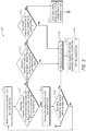
- FIG. 6 is a flowchart representation of a method 600 of pre-routing multicast flows within a network to reduce joining latency in accordance with some implementations.
- the method 600 is performed by a controller (e.g., the controller 120 in FIG. 1 , FIGS. 3A-3F , and FIGS. 4A-4F ).
- the method 600 is performed by processing logic, including hardware, firmware, software, or a combination thereof.
- the method 600 is performed by a processor executing code stored in a non-transitory computer-readable medium (e.g., a memory).
- the method 600 includes determining a current termination node for first and second multicast flows.
- the controller 120 or one or more components thereof determine the current termination node for the first and second multicast flows in response to detecting a trigger event such as instantiation of the first and second multicast flows or reception a command from an application to pre-route multicast flows in order to reduce associated joining latency.
- a trigger event such as instantiation of the first and second multicast flows or reception a command from an application to pre-route multicast flows in order to reduce associated joining latency.
- the controller 120 or one or more components thereof determine that the MC node 206 A is the current termination node of the multicast flows 410 and 420 .
- the method 600 includes determining whether a link between the current termination node and a downstream node has available BW to accommodate the first and second multicast flows.
- the controller 120 or one or more components thereof determine whether the link between the current termination node (determined in block 6 - 1 ) and the downstream node has sufficient available BW to accommodate both of the first and second multicast flows.
- the downstream node is a downstream next hop node in relation to current termination node. In some implementations, the determination is made with respect to respective links of multiple downstream nodes.
- the determination at block 6 - 2 is discussed independent of similar determinations at other downstream nodes.
- the pre-routing of the flows 410 and 420 in the network 205 shown in FIG. 4A need not happen sequentially in various implementations.
- the controller 120 or one or more components thereof e.g., the BW decision logic 122 and pre-routing logic 126 ) have complete picture of the network 205 and available BW on the links 212 .
- the controller 120 or one or more components thereof determines how far the flows 410 and 420 can be pre-routed within the network 205 and issues pre-routing commands to each of the MC nodes 206 in parallel in order to reduce overall setup time.
- the controller 120 or one or more components thereof perform determinations 450 A and 450 B.
- the controller 120 or one or more components thereof determine whether link 212 A between the MC node 206 A (e.g., the current termination node) and the MC node 206 B (e.g., a first downstream next hop node) has available BW to accommodate both of the multicast flows 410 and 420 .
- the controller 120 or one or more components thereof determine whether link 212 E between the MC node 206 A (e.g., the current termination node) and the MC node 206 F (e.g., a second downstream next hop node) has available BW to accommodate both of the multicast flows 410 and 420 .
- the method 600 continues to block 6 - 5 . As such, a portion of the BW of the link is currently reserved, and the available BW of the link is insufficient to accommodate pre-routing of the first and second multicast flows to the downstream node. If the link between the current termination node and the downstream node has available BW to accommodate the first and second multicast flows (“Yes” path from block 6 - 2 ), the method 600 continues to block 6 - 3 . As such, the available BW of the link is sufficient to accommodate pre-routing of the first and second multicast flows to the downstream node.
- the method 600 includes transmitting the first and second multicast flows to the downstream node.
- the controller 120 or one or more components thereof e.g., the pre-routing logic 126
- the controller 120 or one or more components thereof e.g., the pre-routing logic 126
- the controller 120 or one or more components thereof transmit/route the multicast flows 410 and 420 to the MC node 206 F via tributary multicast flows 414 and 424 , respectively.
- the method 600 includes determining whether the downstream node is an edge node.
- the controller 120 or one or more components thereof determines whether the downstream node is an edge node.
- the MC nodes 206 D, 206 E, and 206 G correspond to edge nodes of the network 205 .
- an edge node is gateway node to an end-user node/device.
- an edge node is associated with the edge of the core network, and the edge node is communicatively coupled with a gateway node to an end-user node/device.
- the method 600 continues to block 6 - 11 . As such, the controller 120 has pre-routed the multicast flows to the edge of the core network. According to some embodiment, the controller 120 ceases to pre-route the multicast flow once the multicast flow reaches an edge node. If the downstream node is not the edge node (“No” path from block 6 - 4 ), the method 600 continues to block 6 - 1 . As such, the controller 120 has pre-routed the multicast flows to a non-edge node of the core network. According to some embodiment, the controller 120 continues to pre-route the multicast flows until the multicast flows reach an edge node.
- the method 600 includes determining whether the link between the current termination node and a downstream node has available BW to accommodate one of the first and second multicast flows.
- the controller 120 or one or more components thereof determine whether the link between the current termination node (determined in block 5 - 1 ) and the downstream node has sufficient available BW to accommodate one of the first and second multicast flows. For example, with reference to FIG.
- the controller 120 or one or more components thereof determine whether link 212 C between the MC node 206 C (e.g., the current termination node) and the MC node 206 D (e.g., a first downstream next hop node) has available BW to accommodate either of the tributary multicast flows 412 and 422 .
- the controller 120 or one or more components thereof determine whether link 212 C between the MC node 206 C (e.g., the current termination node) and the MC node 206 D (e.g., a first downstream next hop node) has available BW to accommodate either of the tributary multicast flows 412 and 422 .
- the controller 120 or one or more components thereof determine whether link 212 H between the MC node 206 C (e.g., the current termination node) and the MC node 206 H (e.g., a second downstream next hop node) has available BW to accommodate either of the tributary multicast flows 412 and 422 .
- the method 600 continues to block 6 - 6 .
- the available BW of the link is sufficient to accommodate pre-routing of one of the first or second multicast flows to the downstream node.
- the BW of the link 212 C is 100 Gbps
- the current reserved BW associated with the link 212 A is 75 Gbps.
- the available BW of the link 212 C is 35 Gbps.
- the BW of the tributary multicast flow 412 is 15 Gbps and the BW of the tributary multicast flow 422 is 15 Gbps.
- the link 212 C has sufficient BW to accommodate one but not both of the tributary multicast flows 412 and 422 because the available BW of the link 212 C is less than sum of the BW of the tributary multicast flows 412 and 422 (e.g., 25 Gbps ⁇ 30 Gbps).
- the method 600 continues to block 6 - 8 .
- a portion of the BW of the link is currently reserved, and the available BW of the link is insufficient to accommodate pre-routing of either the first or second multicast flows to the downstream node.
- the BW of the link 212 H is 100 Gbps, and the current reserved BW associated with the link 212 A is 90 Gbps.
- the available BW of the link 212 H is 10 Gbps.
- the BW of the tributary multicast flow 412 is 15 Gbps and the BW of the tributary multicast flow 422 is 15 Gbps.
- the link 212 H has insufficient BW to accommodate either of the tributary multicast flows 412 or 422 because the available BW of the link 212 H is less than sum of the BW of the tributary multicast flows 412 and 422 (e.g., 10 Gbps ⁇ 30 Gbps).
- the method 600 includes prioritizing the first and second multicast flows.
- the controller 120 or one or more components thereof determine a prioritization value for each of the first and second multicast flows.
- a prioritization value for a respective multicast flow is a function of at least one of: the bitrate of the respective multicast flow, a number of listeners of the respective multicast flow, the content type of respective multicast flow (e.g., audio flows have higher prioritization values than video flows), an importance value set by the MC source node, an importance value set by the destination node, or the like.
- a prioritization value for a respective multicast flow is a reflection of how frequently and/or how soon a flow is likely to be requested by a client device (e.g., one of the destination nodes 204 in FIGS. 3A-3F ). For example, this is calculated by the controller 120 or the destination nodes 204 based on predicted and/or historic traffic statistics, and/or the like.
- the method 600 includes transmitting the higher priority multicast flow to the downstream node.
- the controller 120 or one or more components thereof e.g., the pre-routing logic 126 ) transmit/route the tributary multicast flow 422 (e.g., the higher priority multicast flow) from the MC node 206 C to the MC node 206 D and maintain the tributary multicast flow 412 (e.g., the lower priority multicast flow) at the MC node 206 C.
- the method 600 includes determining whether the first and/or second multicast flows have a higher priority than any other flow pre-routed to the downstream node. According to some implementations, after determining that the link between the current termination node and the downstream node does not have available BW to accommodate the first and second multicast flows, the controller 120 or one or more components thereof (e.g., the prioritization logic 124 ) determine whether the first and/or second multicast flows have a higher prioritization value than any other flows previously pre-routed to the downstream node.
- the controller 120 or one or more components thereof determine whether the first and/or second multicast flows have a higher prioritization value than any other flows previously pre-routed to the downstream node.
- the method 600 continues to block 6 - 9 . If the first and second multicast flows do not have a higher priority than any other flow pre-routed to the downstream node (“No” path from block 6 - 8 ), the method 600 continues to block 6 - 11 .
- the method 600 includes determining whether the sum of the bandwidth (BW) used by lower priority flow(s) is greater than or equal to the BW of the first and/or second multicast flows.
- the controller 120 or one or more components thereof determines whether the one or more other flows with lower prioritization values are associated with a greater or equal amount of bandwidth as the first and/or second multicast flows.
- the method 600 continues to block 6 - 10 . If the sum of the BW used by the lower priority flow(s) is less than the BW of the first and/or second multicast flows (“No” path from block 6 - 9 ), the method 600 continues to block 6 - 11 .
- the method 600 includes evicting at least some the lower priority flow(s) and transmitting the first and/or second multicast flows to the downstream node.
- the controller 120 or one or more components thereof e.g., the pre-routing logic 126 ) evict at least some the one or more other flows from the downstream node and routes the first and/or second multicast flows to the downstream node. For example, the controller 120 evicts the lowest priority flow(s) for which the sum of their associated BW is greater than or equal the BW associated with the first and/or second multicast flows.
- the controller 120 or one or more components thereof e.g., the pre-routing logic 126 ) evict the one or more other flows from the downstream node and routes the flow with the higher prioritization value from among the first and second multicast flows.
- the method 600 includes maintaining the first and second multicast flows at the current terminal node (e.g., the current termination node determined in block 6 - 1 or the downstream node to which the first and/or second multicast flows were transmitted to in blocks 6 - 3 , 6 - 7 , or 6 - 10 ).
- the current terminal node e.g., the current termination node determined in block 6 - 1 or the downstream node to which the first and/or second multicast flows were transmitted to in blocks 6 - 3 , 6 - 7 , or 6 - 10 .
- the controller 120 or one or more components thereof forego transmitting the tributary multicast flows 412 and 422 from the MC node 206 C to the MC node 206 H.
- the method 600 optionally includes monitoring available BW of links associated with the first and second multicast flows between its upstream source and the current terminal node.
- the controller 120 or one or more components thereof monitor the available BW of links associated with the first and/or second multicast flows. For example, with reference to FIG. 4D , the controller 120 or one or more components thereof monitor the available BW of links 212 A, 212 B, 212 C, 212 E, and 212 F.
- the method 600 optionally includes trimming the first multicast flow.
- the controller 120 or one or more components thereof e.g., the BW decision logic 122 ) dynamically determine whether links associated with the first and/or second multicast flows have sufficient available BW to accommodate one or both of the first and/or second multicast flows. If a respective link associated with the first and second multicast flow has insufficient available BW to accommodate either of the first or second multicast flows, the first and second multicast flows are pruned (or evicted) from the respective link. For example, a new unicast flow that traverses the link reserves a predetermined amount of BW that causes the respective link to no longer have sufficient available BW to accommodate the first and second multicast flows.
- the controller 120 or one or more components thereof prunes the tributary multicast flow 412 (e.g., the lower priority multicast flow) from the link 212 B and continues to route the tributary multicast flow 422 (e.g., the higher priority multicast flow) to the MC node 206 C.
- the tributary multicast flow 412 e.g., the lower priority multicast flow
- the tributary multicast flow 422 e.g., the higher priority multicast flow
- the available BW of the link 212 B is insufficient to accommodate both of the tributary multicast flows 412 and 422 due to a change in BW demand (e.g., a new flow or tunnel reserves additional BW).
- the link 212 B still has available BW to accommodate one of the tributary multicast flows 412 or 422 .
- FIG. 7 is a flowchart representation of a method 700 of routing a multicast flow in accordance with some implementations.
- the method 700 is performed by a controller (e.g., the controller 120 in FIG. 1 , FIGS. 3A-3F , and FIGS. 4A-4F ).
- the method 700 is performed by processing logic, including hardware, firmware, software, or a combination thereof.
- the method 700 is performed by a processor executing code stored in a non-transitory computer-readable medium (e.g., a memory).
- the method 700 includes detecting a request to join a flow.
- the controller 120 or one or more components thereof detects the join request 322 from the destination node 204 D.
- the method 700 includes determining how far the associated flow is pre-routed. For example, with reference to FIG. 3D , in response to detecting the join request 322 , the controller 120 or one or more components thereof determine how far the multicast flow 310 (or the tributary multicast flow 314 ) is pre-routed within the network 205 .
- the method 700 includes computing a path from the source node to a destination node based on the pre-routing determination. For example, with reference to FIG. 3D , the controller 120 or one or more components thereof compute a path from the MC source node 202 A to the destination node 204 D based on the closest MC node to which the multicast flow 310 is pre-routed (e.g., the MC node 206 F).
- the method 700 includes pruning other pre-routed flows.
- the controller 120 or one or more components thereof evict pre-routed flows from the MC nodes 206 in the computed path if any of the links in the computed path have insufficient BW to accommodate the multicast flow 310 (or the tributary multicast flow 314 ).
- the method 700 includes sending routing requests to all nodes in the computed path.
- the controller 120 or one or more components thereof send routing requests to the MC nodes 206 in the computed path (e.g., in parallel) to build a multicast distribution tree from the MC source node 202 A to the destination node 204 D (e.g., a multicast routing tree).
- the method 700 includes routing the flow from the source node to the destination node according to the computed path. For example, with reference to FIG. 3D , after building the multicast distribution tree for the multicast flow 310 (or the tributary multicast flow 314 ), the controller 120 or one or more components thereof route the tributary multicast flow 314 from the MC node 206 F through the MC node 206 G to the destination node 204 D according to the computed path.
- FIG. 8 is a flowchart representation of a method 800 of routing a multicast flow in accordance with some implementations.
- the method 800 is performed by a controller (e.g., the controller 120 in FIG. 1 , FIGS. 3A-3F , and FIGS. 4A-4F ).
- the method 800 is performed by processing logic, including hardware, firmware, software, or a combination thereof.
- the method 800 is performed by a processor executing code stored in a non-transitory computer-readable medium (e.g., a memory).
- the method 800 includes receiving a setup request.
- the controller 120 receives a flow setup request from an external entity such as a broadcast controller.
- the method 800 includes identifying a flow, source node, and a destination node associated with the setup request. For example, with reference to FIG. 3A , the controller 120 identifies a flow, one of the MC source nodes 202 , and at least one of the destination nodes 204 based on the flow setup request.
- the method 800 includes determining how far the associated flow is pre-routed. example, with reference to FIG. 3A , the controller 120 determines how far the flow has been pre-routed within the network 205 .
- the method 800 includes computing a path from the source node to a destination node based on the pre-routing determination. For example, with reference to FIG. 3A , the controller 120 computes a path from one of the MC source nodes 202 to at least one of the destination nodes 204 based on the closest one of the MC nodes 206 to which the flow 310 is pre-routed.
- the method 800 includes pruning other pre-routed flows. For example, with reference to FIG. 3A , the controller 120 evicts pre-routed flows from the MC nodes in the computed path if any of the links in the computed path have insufficient BW to accommodate the flow.
- the method 800 includes sending a routing requests to all nodes in the computed path.
- the controller 120 sends routing requests to the MC nodes 206 in the computed path (e.g., in parallel) to build a multicast distribution tree from one of the MC source nodes 202 to at least one of the destination nodes 204 .
- the method 800 includes routing the flow from the source node to the destination node according to the computed path.
- the controller 120 routes the flow from one of the MC source nodes 202 to at least one of the destination nodes 204 according to the computed path.
- FIG. 9 is a block diagram of an example of a device 900 in accordance with some implementations.
- the device 900 is similar to and adapted from the controller 120 in FIG. 1 , FIGS. 3A-3F , and FIGS. 4A-4F . While certain specific features are illustrated, those skilled in the art will appreciate from the present disclosure that various other features have not been illustrated for the sake of brevity, and so as not to obscure more pertinent aspects of the implementations disclosed herein.
- the device 900 includes one or more processing units (CPUs) 902 , a network interface 903 , a memory 910 , a programming (I/O) interface 905 , and one or more communication buses 904 for interconnecting these and various other components.
- CPUs processing units
- network interface 903 a network interface 903
- memory 910 a memory 910
- programming (I/O) interface 905 a programming (I/O) interface 905
- communication buses 904 for interconnecting these and various other components.
- the one or more communication buses 904 include circuitry that interconnects and controls communications between system components.
- the memory 910 includes high-speed random access memory, such as DRAM, SRAM, DDR RAM, or other random access solid state memory devices.
- the memory 910 includes non-volatile memory, such as one or more magnetic disk storage devices, optical disk storage devices, flash memory devices, or other non-volatile solid state storage devices.
- the memory 910 optionally includes one or more storage devices remotely located from the one or more CPUs 902 .
- the memory 910 comprises a non-transitory computer readable storage medium.
- the memory 910 or the non-transitory computer readable storage medium of the memory 910 stores the following programs, modules and data structures, or a subset thereof including an optional operating system 920 , a flow detecting module 930 , a trigger detecting module 932 , a bandwidth (BW) determining module 934 , a prioritizing module 936 , a flow pre-routing module 938 , a monitoring module 940 , a trimming module 942 , and a flow providing module 944 .
- an optional operating system 920 a flow detecting module 930 , a trigger detecting module 932 , a bandwidth (BW) determining module 934 , a prioritizing module 936 , a flow pre-routing module 938 , a monitoring module 940 , a trimming module 942 , and a flow providing module 944 .
- BW bandwidth
- the operating system 920 includes procedures for handling various basic system services and for performing hardware dependent tasks.
- the flow detecting module 930 is configured to determine the current termination node for multicast flow(s). To that end, in various implementations, the flow detecting module 930 includes instructions and/or logic 931 a , and heuristics and metadata 931 b.
- the trigger detecting module 932 is configured to detect a trigger event, such as instantiation of the multicast flow or reception a command from an application, to pre-route multicast flows in order to reduce associated joining latency.
- a trigger event such as instantiation of the multicast flow or reception a command from an application
- the trigger detecting module 932 includes instructions and/or logic 933 a , and heuristics and metadata 933 b.
- the BW determining module 934 is configured to determine whether a link between a current termination node and a downstream node has available BW to accommodate multicast flow(s). To that end, in various implementations, the BW determining module 934 includes instructions and/or logic 935 a , and heuristics and metadata 935 b.
- the prioritizing module 936 is configured to determine priority values for two or more multicast flows when a link has sufficient BW to accommodate one of the two or more multicast flows. To that end, in various implementations, the prioritizing module 936 includes instructions and/or logic 937 a , and heuristics and metadata 937 b.
- the flow pre-routing module 938 is configured to transmit/route the multicast flow from the current termination node to the downstream node based on determinations by the BW determining module 934 and/or the prioritizing module 936 .
- the flow pre-routing module 938 includes instructions and/or logic 939 a , and heuristics and metadata 939 b.
- the monitoring module 940 is configured to monitor the available bandwidth of links associated with the multicast flows pre-routed by the flow pre-routing module 938 .
- the monitoring module 940 includes instructions and/or logic 941 a , and heuristics and metadata 941 b.
- the trimming module 942 is configured to evict pre-routed multicast flows from links that no longer have available BW to accommodate the pre-routed multicast flows.
- the trimming module 942 includes instructions and/or logic 943 a , and heuristics and metadata 943 b.
- the flow providing module 944 is configured to route a multicast flow to a destination in response to a request to join or subscribe to the multicast flow.
- the flow providing module 944 includes instructions and/or logic 945 a , and heuristics and metadata 945 b.
- the flow detecting module 930 , the trigger detecting module 932 , the BW determining module 934 , the prioritizing module 936 , the flow pre-routing module 938 , the monitoring module 940 , the trimming module 942 , and the flow providing module 944 are illustrated as residing on a single device (i.e., the device 900 ), it should be understood that in other implementations, any combination of the flow detecting module 930 , the trigger detecting module 932 , the BW determining module 934 , the prioritizing module 936 , the flow pre-routing module 938 , the monitoring module 940 , the trimming module 942 , and the flow providing module 944 reside on a separate device.
- FIG. 9 is intended more as functional description of the various features which be present in a particular embodiment as opposed to a structural schematic of the implementations described herein.
- items shown separately could be combined and some items could be separated.
- some functional modules shown separately in FIG. 9 could be implemented in a single module and the various functions of single functional blocks could be implemented by one or more functional blocks in various implementations.
- the actual number of modules and the division of particular functions and how features are allocated among them will vary from one embodiment to another and, in some implementations, depends in part on the particular combination of hardware, software, and/or firmware chosen for a particular embodiment.
- first first
- second second
- first node first node
- first node second node
- first node first node
- second node second node
- the first node and the second node are both nodes, but they are not the same node.
- the term “if” may be construed to mean “when” or “upon” or “in response to determining” or “in accordance with a determination” or “in response to detecting,” that a stated condition precedent is true, depending on the context.
- the phrase “if it is determined [that a stated condition precedent is true]” or “if [a stated condition precedent is true]” or “when [a stated condition precedent is true]” may be construed to mean “upon determining” or “in response to determining” or “in accordance with a determination” or “upon detecting” or “in response to detecting” that the stated condition precedent is true, depending on the context.
Abstract
Description
Claims (20)
Priority Applications (1)
| Application Number | Priority Date | Filing Date | Title |
|---|---|---|---|
| US15/389,960 US10560359B2 (en) | 2016-12-23 | 2016-12-23 | Method and device for reducing multicast flow joint latency |
Applications Claiming Priority (1)
| Application Number | Priority Date | Filing Date | Title |
|---|---|---|---|
| US15/389,960 US10560359B2 (en) | 2016-12-23 | 2016-12-23 | Method and device for reducing multicast flow joint latency |
Publications (2)
| Publication Number | Publication Date |
|---|---|
| US20180183697A1 US20180183697A1 (en) | 2018-06-28 |
| US10560359B2 true US10560359B2 (en) | 2020-02-11 |
Family
ID=62630318
Family Applications (1)
| Application Number | Title | Priority Date | Filing Date |
|---|---|---|---|
| US15/389,960 Expired - Fee Related US10560359B2 (en) | 2016-12-23 | 2016-12-23 | Method and device for reducing multicast flow joint latency |
Country Status (1)
| Country | Link |
|---|---|
| US (1) | US10560359B2 (en) |
Families Citing this family (2)
| Publication number | Priority date | Publication date | Assignee | Title |
|---|---|---|---|---|
| US10743332B2 (en) * | 2016-11-18 | 2020-08-11 | Qualcomm Incorporated | Techniques and apparatuses for complementary transmission relating to an interrupted traffic flow in new radio |
| US11575775B2 (en) * | 2017-01-04 | 2023-02-07 | Extreme Networks, Inc. | Overlay IP multicast over unicast IP networks |
Citations (19)
| Publication number | Priority date | Publication date | Assignee | Title |
|---|---|---|---|---|
| US20020072383A1 (en) * | 2000-12-01 | 2002-06-13 | Motorola, Inc. | Method for managing bandwidth in a packet-based communication system using call unit reservations |
| US20030002448A1 (en) * | 2001-06-29 | 2003-01-02 | Laursen Arthur I. | Method and system for distributed conference bridge processing |
| US20030073453A1 (en) * | 2001-10-11 | 2003-04-17 | Henrik Basilier | Systems and methods for multicast communications |
| US20040218595A1 (en) * | 2003-05-02 | 2004-11-04 | Lucent Technologies Inc. | System and method for multi-protocol label switching network tuning |
| US20040258066A1 (en) * | 2003-05-23 | 2004-12-23 | Shiwen Chen | Architecture for dense multicast networks with provisioned routes |
| US20050129017A1 (en) | 2003-12-11 | 2005-06-16 | Alcatel | Multicast flow accounting |
| US20060074968A1 (en) * | 2004-10-06 | 2006-04-06 | Gyetko Gregory E | Electronic content distribution management methods and systems |
| US20060268871A1 (en) * | 2005-01-26 | 2006-11-30 | Erik Van Zijst | Layered multicast and fair bandwidth allocation and packet prioritization |
| US20070201365A1 (en) * | 2006-01-23 | 2007-08-30 | Frederick Skoog | Video packet multiplexer with intelligent packet discard |
| US20090175274A1 (en) * | 2005-07-28 | 2009-07-09 | Juniper Networks, Inc. | Transmission of layer two (l2) multicast traffic over multi-protocol label switching networks |
| US20090252033A1 (en) * | 2008-04-08 | 2009-10-08 | At&T Knowledge Ventures, L.P. | System and method of distributing media content |
| US20110019534A1 (en) * | 2009-07-27 | 2011-01-27 | At&T Intellectual Property I, L.P. | Systems and Methods of Multicast Reconfiguration Using Cross-Layer Information |
| US7933267B1 (en) | 2004-08-30 | 2011-04-26 | Juniper Networks, Inc. | Shared multicast trees for multicast virtual private networks |
| CN102480692A (en) | 2011-12-31 | 2012-05-30 | 浙江工商大学 | As-demanded multicast routing method of distributed bandwidth constraint in Wireless Ad Hoc Networks |
| US8392605B2 (en) | 2005-03-21 | 2013-03-05 | Zte Corporation | Method of fast-multicast and a system thereof |
| US20130114595A1 (en) * | 2011-11-04 | 2013-05-09 | Futurewei Technologies, Co. | Method for Multicast Flow Routing Selection |
| CN104683244A (en) | 2015-03-09 | 2015-06-03 | 东北大学 | Multicast routing method based on route node driving strategy |
| WO2016019527A1 (en) | 2014-08-06 | 2016-02-11 | 华为技术有限公司 | Point-to-multipoint communication method and communication node based on mesh structure |
| US9300591B2 (en) | 2013-01-28 | 2016-03-29 | Schweitzer Engineering Laboratories, Inc. | Network device |
-
2016
- 2016-12-23 US US15/389,960 patent/US10560359B2/en not_active Expired - Fee Related
Patent Citations (19)
| Publication number | Priority date | Publication date | Assignee | Title |
|---|---|---|---|---|
| US20020072383A1 (en) * | 2000-12-01 | 2002-06-13 | Motorola, Inc. | Method for managing bandwidth in a packet-based communication system using call unit reservations |
| US20030002448A1 (en) * | 2001-06-29 | 2003-01-02 | Laursen Arthur I. | Method and system for distributed conference bridge processing |
| US20030073453A1 (en) * | 2001-10-11 | 2003-04-17 | Henrik Basilier | Systems and methods for multicast communications |
| US20040218595A1 (en) * | 2003-05-02 | 2004-11-04 | Lucent Technologies Inc. | System and method for multi-protocol label switching network tuning |
| US20040258066A1 (en) * | 2003-05-23 | 2004-12-23 | Shiwen Chen | Architecture for dense multicast networks with provisioned routes |
| US20050129017A1 (en) | 2003-12-11 | 2005-06-16 | Alcatel | Multicast flow accounting |
| US7933267B1 (en) | 2004-08-30 | 2011-04-26 | Juniper Networks, Inc. | Shared multicast trees for multicast virtual private networks |
| US20060074968A1 (en) * | 2004-10-06 | 2006-04-06 | Gyetko Gregory E | Electronic content distribution management methods and systems |
| US20060268871A1 (en) * | 2005-01-26 | 2006-11-30 | Erik Van Zijst | Layered multicast and fair bandwidth allocation and packet prioritization |
| US8392605B2 (en) | 2005-03-21 | 2013-03-05 | Zte Corporation | Method of fast-multicast and a system thereof |
| US20090175274A1 (en) * | 2005-07-28 | 2009-07-09 | Juniper Networks, Inc. | Transmission of layer two (l2) multicast traffic over multi-protocol label switching networks |
| US20070201365A1 (en) * | 2006-01-23 | 2007-08-30 | Frederick Skoog | Video packet multiplexer with intelligent packet discard |
| US20090252033A1 (en) * | 2008-04-08 | 2009-10-08 | At&T Knowledge Ventures, L.P. | System and method of distributing media content |
| US20110019534A1 (en) * | 2009-07-27 | 2011-01-27 | At&T Intellectual Property I, L.P. | Systems and Methods of Multicast Reconfiguration Using Cross-Layer Information |
| US20130114595A1 (en) * | 2011-11-04 | 2013-05-09 | Futurewei Technologies, Co. | Method for Multicast Flow Routing Selection |
| CN102480692A (en) | 2011-12-31 | 2012-05-30 | 浙江工商大学 | As-demanded multicast routing method of distributed bandwidth constraint in Wireless Ad Hoc Networks |
| US9300591B2 (en) | 2013-01-28 | 2016-03-29 | Schweitzer Engineering Laboratories, Inc. | Network device |
| WO2016019527A1 (en) | 2014-08-06 | 2016-02-11 | 华为技术有限公司 | Point-to-multipoint communication method and communication node based on mesh structure |
| CN104683244A (en) | 2015-03-09 | 2015-06-03 | 东北大学 | Multicast routing method based on route node driving strategy |
Also Published As
| Publication number | Publication date |
|---|---|
| US20180183697A1 (en) | 2018-06-28 |
Similar Documents
| Publication | Publication Date | Title |
|---|---|---|
| US10230620B2 (en) | Multicast traffic management within a wireless mesh network | |
| EP3677013B1 (en) | Replication with dedicated metal deployment in a cloud | |
| EP2622805B1 (en) | Method for pruning a multicast branch, protocol independent multicast router, and layer-2 exchange | |
| JP4825696B2 (en) | Packet relay device | |
| US20140185450A1 (en) | Apparatus for a High Performance and Highly Available Multi-Controllers in a Single SDN/OpenFlow Network | |
| CN109981308B (en) | Message transmission method and device | |
| US20140226525A1 (en) | Safe Multicast Distribution with Predictable Topology Changes | |
| US9160683B2 (en) | Providing PIM-SSM support for MRSVP-TE based multicast virtual private networks | |
| CN109196819B (en) | Bidirectional multicast over virtual port channels | |
| US9130857B2 (en) | Protocol independent multicast with quality of service support | |
| US20190238949A1 (en) | Multicast service providing method and software defined networking controller | |
| CN109391551B (en) | Multi-port multicast method, equipment and computer readable storage medium | |
| US9030926B2 (en) | Protocol independent multicast last hop router discovery | |
| US11245618B2 (en) | Multicast traceroute facility with batch query processing for multiple flows and reservation of resources for requested link metrics | |
| US10560359B2 (en) | Method and device for reducing multicast flow joint latency | |
| US11695686B2 (en) | Source-initiated distribution of spine node identifiers of preferred spine nodes for use in multicast path selection | |
| US9036462B2 (en) | Internet group management protocol version three for quality of service support | |
| US20180323989A1 (en) | Methods, apparatuses and computer-readable mediums for managing multicast channels in access networks | |
| WO2012103748A1 (en) | Multicast control method, routing device and multicast system | |
| US20120047405A1 (en) | Method for using a computer network | |
| US11018886B1 (en) | Methods and apparatus for selectively filtering an IP multicast data stream for selected group members of a multicast group | |
| US11329907B2 (en) | Establishing a multicast flow path through a network using multicast resources currently associated with a different multicast flow path | |
| CA2902402A1 (en) | Multicast traffic management within a wireless mesh network | |
| US9819514B2 (en) | Processing stream messages |
Legal Events
| Date | Code | Title | Description |
|---|---|---|---|
| AS | Assignment |
Owner name: CISCO TECHNOLOGY, INC., CALIFORNIA Free format text: ASSIGNMENT OF ASSIGNORS INTEREST;ASSIGNORS:DHESIKAN, SUBHASRI;KATHAIL, PRADEEP KUMAR;SIGNING DATES FROM 20161208 TO 20161222;REEL/FRAME:040760/0063 |
|
| STPP | Information on status: patent application and granting procedure in general |
Free format text: FINAL REJECTION MAILED |
|
| STPP | Information on status: patent application and granting procedure in general |
Free format text: DOCKETED NEW CASE - READY FOR EXAMINATION |
|
| STPP | Information on status: patent application and granting procedure in general |
Free format text: NOTICE OF ALLOWANCE MAILED -- APPLICATION RECEIVED IN OFFICE OF PUBLICATIONS |
|
| STPP | Information on status: patent application and granting procedure in general |
Free format text: PUBLICATIONS -- ISSUE FEE PAYMENT VERIFIED |
|
| STCF | Information on status: patent grant |
Free format text: PATENTED CASE |
|
| FEPP | Fee payment procedure |
Free format text: MAINTENANCE FEE REMINDER MAILED (ORIGINAL EVENT CODE: REM.); ENTITY STATUS OF PATENT OWNER: LARGE ENTITY |
|
| LAPS | Lapse for failure to pay maintenance fees |
Free format text: PATENT EXPIRED FOR FAILURE TO PAY MAINTENANCE FEES (ORIGINAL EVENT CODE: EXP.); ENTITY STATUS OF PATENT OWNER: LARGE ENTITY |
|
| STCH | Information on status: patent discontinuation |
Free format text: PATENT EXPIRED DUE TO NONPAYMENT OF MAINTENANCE FEES UNDER 37 CFR 1.362 |
|
| FP | Lapsed due to failure to pay maintenance fee |
Effective date: 20240211 |