US10558908B2 - Age and gender estimation using small-scale convolutional neural network (CNN) modules for embedded systems - Google Patents
Age and gender estimation using small-scale convolutional neural network (CNN) modules for embedded systems Download PDFInfo
- Publication number
- US10558908B2 US10558908B2 US15/724,256 US201715724256A US10558908B2 US 10558908 B2 US10558908 B2 US 10558908B2 US 201715724256 A US201715724256 A US 201715724256A US 10558908 B2 US10558908 B2 US 10558908B2
- Authority
- US
- United States
- Prior art keywords
- input
- size
- image
- cnn
- module
- Prior art date
- Legal status (The legal status is an assumption and is not a legal conclusion. Google has not performed a legal analysis and makes no representation as to the accuracy of the status listed.)
- Active, expires
Links
- 238000013527 convolutional neural network Methods 0.000 title claims abstract description 582
- 238000001514 detection method Methods 0.000 claims description 154
- 238000000034 method Methods 0.000 claims description 148
- 238000012545 processing Methods 0.000 claims description 95
- 230000008569 process Effects 0.000 claims description 85
- 238000005192 partition Methods 0.000 claims description 53
- 238000011176 pooling Methods 0.000 claims description 41
- 238000000638 solvent extraction Methods 0.000 claims description 29
- 239000013598 vector Substances 0.000 claims description 18
- 238000013135 deep learning Methods 0.000 claims description 13
- 238000011065 in-situ storage Methods 0.000 claims description 7
- 102100033620 Calponin-1 Human genes 0.000 description 48
- 101000945318 Homo sapiens Calponin-1 Proteins 0.000 description 48
- 230000001815 facial effect Effects 0.000 description 35
- 102100033591 Calponin-2 Human genes 0.000 description 30
- 101000945403 Homo sapiens Calponin-2 Proteins 0.000 description 30
- 210000000887 face Anatomy 0.000 description 29
- 238000010586 diagram Methods 0.000 description 27
- 230000033001 locomotion Effects 0.000 description 24
- 238000013528 artificial neural network Methods 0.000 description 20
- 238000003860 storage Methods 0.000 description 17
- 238000013461 design Methods 0.000 description 16
- 238000005516 engineering process Methods 0.000 description 11
- 238000013459 approach Methods 0.000 description 7
- 239000011159 matrix material Substances 0.000 description 7
- 210000001331 nose Anatomy 0.000 description 7
- 230000006870 function Effects 0.000 description 6
- 230000004807 localization Effects 0.000 description 6
- 238000001914 filtration Methods 0.000 description 5
- 238000012549 training Methods 0.000 description 5
- 238000013136 deep learning model Methods 0.000 description 3
- 238000010801 machine learning Methods 0.000 description 3
- 230000007246 mechanism Effects 0.000 description 3
- 210000002569 neuron Anatomy 0.000 description 3
- 230000003287 optical effect Effects 0.000 description 3
- 238000013473 artificial intelligence Methods 0.000 description 2
- 238000005286 illumination Methods 0.000 description 2
- 238000012886 linear function Methods 0.000 description 2
- 238000003909 pattern recognition Methods 0.000 description 2
- 238000007781 pre-processing Methods 0.000 description 2
- 230000008521 reorganization Effects 0.000 description 2
- 238000000926 separation method Methods 0.000 description 2
- 230000006399 behavior Effects 0.000 description 1
- 230000009286 beneficial effect Effects 0.000 description 1
- 230000008901 benefit Effects 0.000 description 1
- 230000003139 buffering effect Effects 0.000 description 1
- 230000008859 change Effects 0.000 description 1
- 230000001010 compromised effect Effects 0.000 description 1
- 238000004590 computer program Methods 0.000 description 1
- 238000013434 data augmentation Methods 0.000 description 1
- 238000011161 development Methods 0.000 description 1
- 230000000694 effects Effects 0.000 description 1
- 238000000605 extraction Methods 0.000 description 1
- 230000014509 gene expression Effects 0.000 description 1
- 239000004973 liquid crystal related substance Substances 0.000 description 1
- 229910052754 neon Inorganic materials 0.000 description 1
- GKAOGPIIYCISHV-UHFFFAOYSA-N neon atom Chemical compound [Ne] GKAOGPIIYCISHV-UHFFFAOYSA-N 0.000 description 1
- 230000006855 networking Effects 0.000 description 1
- 238000010606 normalization Methods 0.000 description 1
- 230000002093 peripheral effect Effects 0.000 description 1
- 230000004044 response Effects 0.000 description 1
- 238000012552 review Methods 0.000 description 1
- 230000003068 static effect Effects 0.000 description 1
- 230000001629 suppression Effects 0.000 description 1
- 238000012360 testing method Methods 0.000 description 1
- 230000000007 visual effect Effects 0.000 description 1
Images


Classifications
-
- G—PHYSICS
- G06—COMPUTING; CALCULATING OR COUNTING
- G06V—IMAGE OR VIDEO RECOGNITION OR UNDERSTANDING
- G06V40/00—Recognition of biometric, human-related or animal-related patterns in image or video data
- G06V40/10—Human or animal bodies, e.g. vehicle occupants or pedestrians; Body parts, e.g. hands
- G06V40/16—Human faces, e.g. facial parts, sketches or expressions
- G06V40/172—Classification, e.g. identification
-
- G—PHYSICS
- G06—COMPUTING; CALCULATING OR COUNTING
- G06N—COMPUTING ARRANGEMENTS BASED ON SPECIFIC COMPUTATIONAL MODELS
- G06N3/00—Computing arrangements based on biological models
- G06N3/02—Neural networks
- G06N3/04—Architecture, e.g. interconnection topology
- G06N3/0464—Convolutional networks [CNN, ConvNet]
-
- G—PHYSICS
- G06—COMPUTING; CALCULATING OR COUNTING
- G06F—ELECTRIC DIGITAL DATA PROCESSING
- G06F18/00—Pattern recognition
- G06F18/20—Analysing
- G06F18/21—Design or setup of recognition systems or techniques; Extraction of features in feature space; Blind source separation
- G06F18/214—Generating training patterns; Bootstrap methods, e.g. bagging or boosting
-
- G—PHYSICS
- G06—COMPUTING; CALCULATING OR COUNTING
- G06F—ELECTRIC DIGITAL DATA PROCESSING
- G06F18/00—Pattern recognition
- G06F18/20—Analysing
- G06F18/24—Classification techniques
- G06F18/241—Classification techniques relating to the classification model, e.g. parametric or non-parametric approaches
- G06F18/2413—Classification techniques relating to the classification model, e.g. parametric or non-parametric approaches based on distances to training or reference patterns
- G06F18/24133—Distances to prototypes
- G06F18/24143—Distances to neighbourhood prototypes, e.g. restricted Coulomb energy networks [RCEN]
-
- G06K9/00228—
-
- G06K9/00268—
-
- G06K9/00275—
-
- G06K9/00288—
-
- G06K9/2054—
-
- G06K9/4628—
-
- G06K9/6232—
-
- G06K9/6256—
-
- G06K9/6274—
-
- G—PHYSICS
- G06—COMPUTING; CALCULATING OR COUNTING
- G06N—COMPUTING ARRANGEMENTS BASED ON SPECIFIC COMPUTATIONAL MODELS
- G06N3/00—Computing arrangements based on biological models
- G06N3/02—Neural networks
- G06N3/04—Architecture, e.g. interconnection topology
-
- G—PHYSICS
- G06—COMPUTING; CALCULATING OR COUNTING
- G06N—COMPUTING ARRANGEMENTS BASED ON SPECIFIC COMPUTATIONAL MODELS
- G06N3/00—Computing arrangements based on biological models
- G06N3/02—Neural networks
- G06N3/04—Architecture, e.g. interconnection topology
- G06N3/045—Combinations of networks
-
- G06N3/0454—
-
- G—PHYSICS
- G06—COMPUTING; CALCULATING OR COUNTING
- G06N—COMPUTING ARRANGEMENTS BASED ON SPECIFIC COMPUTATIONAL MODELS
- G06N3/00—Computing arrangements based on biological models
- G06N3/02—Neural networks
- G06N3/04—Architecture, e.g. interconnection topology
- G06N3/048—Activation functions
-
- G—PHYSICS
- G06—COMPUTING; CALCULATING OR COUNTING
- G06N—COMPUTING ARRANGEMENTS BASED ON SPECIFIC COMPUTATIONAL MODELS
- G06N3/00—Computing arrangements based on biological models
- G06N3/02—Neural networks
- G06N3/06—Physical realisation, i.e. hardware implementation of neural networks, neurons or parts of neurons
- G06N3/063—Physical realisation, i.e. hardware implementation of neural networks, neurons or parts of neurons using electronic means
-
- G—PHYSICS
- G06—COMPUTING; CALCULATING OR COUNTING
- G06N—COMPUTING ARRANGEMENTS BASED ON SPECIFIC COMPUTATIONAL MODELS
- G06N3/00—Computing arrangements based on biological models
- G06N3/02—Neural networks
- G06N3/08—Learning methods
-
- G—PHYSICS
- G06—COMPUTING; CALCULATING OR COUNTING
- G06T—IMAGE DATA PROCESSING OR GENERATION, IN GENERAL
- G06T5/00—Image enhancement or restoration
- G06T5/50—Image enhancement or restoration using two or more images, e.g. averaging or subtraction
-
- G—PHYSICS
- G06—COMPUTING; CALCULATING OR COUNTING
- G06T—IMAGE DATA PROCESSING OR GENERATION, IN GENERAL
- G06T7/00—Image analysis
- G06T7/10—Segmentation; Edge detection
- G06T7/11—Region-based segmentation
-
- G—PHYSICS
- G06—COMPUTING; CALCULATING OR COUNTING
- G06T—IMAGE DATA PROCESSING OR GENERATION, IN GENERAL
- G06T7/00—Image analysis
- G06T7/20—Analysis of motion
- G06T7/246—Analysis of motion using feature-based methods, e.g. the tracking of corners or segments
- G06T7/248—Analysis of motion using feature-based methods, e.g. the tracking of corners or segments involving reference images or patches
-
- G—PHYSICS
- G06—COMPUTING; CALCULATING OR COUNTING
- G06V—IMAGE OR VIDEO RECOGNITION OR UNDERSTANDING
- G06V10/00—Arrangements for image or video recognition or understanding
- G06V10/40—Extraction of image or video features
- G06V10/44—Local feature extraction by analysis of parts of the pattern, e.g. by detecting edges, contours, loops, corners, strokes or intersections; Connectivity analysis, e.g. of connected components
- G06V10/443—Local feature extraction by analysis of parts of the pattern, e.g. by detecting edges, contours, loops, corners, strokes or intersections; Connectivity analysis, e.g. of connected components by matching or filtering
- G06V10/449—Biologically inspired filters, e.g. difference of Gaussians [DoG] or Gabor filters
- G06V10/451—Biologically inspired filters, e.g. difference of Gaussians [DoG] or Gabor filters with interaction between the filter responses, e.g. cortical complex cells
- G06V10/454—Integrating the filters into a hierarchical structure, e.g. convolutional neural networks [CNN]
-
- G—PHYSICS
- G06—COMPUTING; CALCULATING OR COUNTING
- G06V—IMAGE OR VIDEO RECOGNITION OR UNDERSTANDING
- G06V10/00—Arrangements for image or video recognition or understanding
- G06V10/70—Arrangements for image or video recognition or understanding using pattern recognition or machine learning
- G06V10/82—Arrangements for image or video recognition or understanding using pattern recognition or machine learning using neural networks
-
- G—PHYSICS
- G06—COMPUTING; CALCULATING OR COUNTING
- G06V—IMAGE OR VIDEO RECOGNITION OR UNDERSTANDING
- G06V30/00—Character recognition; Recognising digital ink; Document-oriented image-based pattern recognition
- G06V30/10—Character recognition
- G06V30/19—Recognition using electronic means
- G06V30/191—Design or setup of recognition systems or techniques; Extraction of features in feature space; Clustering techniques; Blind source separation
- G06V30/19173—Classification techniques
-
- G—PHYSICS
- G06—COMPUTING; CALCULATING OR COUNTING
- G06V—IMAGE OR VIDEO RECOGNITION OR UNDERSTANDING
- G06V40/00—Recognition of biometric, human-related or animal-related patterns in image or video data
- G06V40/10—Human or animal bodies, e.g. vehicle occupants or pedestrians; Body parts, e.g. hands
- G06V40/16—Human faces, e.g. facial parts, sketches or expressions
- G06V40/161—Detection; Localisation; Normalisation
-
- G—PHYSICS
- G06—COMPUTING; CALCULATING OR COUNTING
- G06V—IMAGE OR VIDEO RECOGNITION OR UNDERSTANDING
- G06V40/00—Recognition of biometric, human-related or animal-related patterns in image or video data
- G06V40/10—Human or animal bodies, e.g. vehicle occupants or pedestrians; Body parts, e.g. hands
- G06V40/16—Human faces, e.g. facial parts, sketches or expressions
- G06V40/168—Feature extraction; Face representation
- G06V40/169—Holistic features and representations, i.e. based on the facial image taken as a whole
-
- G—PHYSICS
- G06—COMPUTING; CALCULATING OR COUNTING
- G06F—ELECTRIC DIGITAL DATA PROCESSING
- G06F18/00—Pattern recognition
- G06F18/20—Analysing
- G06F18/25—Fusion techniques
- G06F18/251—Fusion techniques of input or preprocessed data
-
- G06K2009/00322—
-
- G06K2209/15—
-
- G06K9/00402—
-
- G06K9/6289—
-
- G—PHYSICS
- G06—COMPUTING; CALCULATING OR COUNTING
- G06T—IMAGE DATA PROCESSING OR GENERATION, IN GENERAL
- G06T2200/00—Indexing scheme for image data processing or generation, in general
- G06T2200/28—Indexing scheme for image data processing or generation, in general involving image processing hardware
-
- G—PHYSICS
- G06—COMPUTING; CALCULATING OR COUNTING
- G06T—IMAGE DATA PROCESSING OR GENERATION, IN GENERAL
- G06T2207/00—Indexing scheme for image analysis or image enhancement
- G06T2207/20—Special algorithmic details
- G06T2207/20021—Dividing image into blocks, subimages or windows
-
- G—PHYSICS
- G06—COMPUTING; CALCULATING OR COUNTING
- G06T—IMAGE DATA PROCESSING OR GENERATION, IN GENERAL
- G06T2207/00—Indexing scheme for image analysis or image enhancement
- G06T2207/20—Special algorithmic details
- G06T2207/20084—Artificial neural networks [ANN]
-
- G—PHYSICS
- G06—COMPUTING; CALCULATING OR COUNTING
- G06T—IMAGE DATA PROCESSING OR GENERATION, IN GENERAL
- G06T2207/00—Indexing scheme for image analysis or image enhancement
- G06T2207/20—Special algorithmic details
- G06T2207/20212—Image combination
- G06T2207/20221—Image fusion; Image merging
-
- G—PHYSICS
- G06—COMPUTING; CALCULATING OR COUNTING
- G06T—IMAGE DATA PROCESSING OR GENERATION, IN GENERAL
- G06T2207/00—Indexing scheme for image analysis or image enhancement
- G06T2207/20—Special algorithmic details
- G06T2207/20212—Image combination
- G06T2207/20224—Image subtraction
-
- G—PHYSICS
- G06—COMPUTING; CALCULATING OR COUNTING
- G06T—IMAGE DATA PROCESSING OR GENERATION, IN GENERAL
- G06T2207/00—Indexing scheme for image analysis or image enhancement
- G06T2207/30—Subject of image; Context of image processing
- G06T2207/30196—Human being; Person
- G06T2207/30201—Face
-
- G—PHYSICS
- G06—COMPUTING; CALCULATING OR COUNTING
- G06T—IMAGE DATA PROCESSING OR GENERATION, IN GENERAL
- G06T2210/00—Indexing scheme for image generation or computer graphics
- G06T2210/12—Bounding box
-
- G—PHYSICS
- G06—COMPUTING; CALCULATING OR COUNTING
- G06V—IMAGE OR VIDEO RECOGNITION OR UNDERSTANDING
- G06V20/00—Scenes; Scene-specific elements
- G06V20/60—Type of objects
- G06V20/62—Text, e.g. of license plates, overlay texts or captions on TV images
- G06V20/625—License plates
-
- G—PHYSICS
- G06—COMPUTING; CALCULATING OR COUNTING
- G06V—IMAGE OR VIDEO RECOGNITION OR UNDERSTANDING
- G06V30/00—Character recognition; Recognising digital ink; Document-oriented image-based pattern recognition
- G06V30/10—Character recognition
- G06V30/32—Digital ink
-
- G—PHYSICS
- G06—COMPUTING; CALCULATING OR COUNTING
- G06V—IMAGE OR VIDEO RECOGNITION OR UNDERSTANDING
- G06V40/00—Recognition of biometric, human-related or animal-related patterns in image or video data
- G06V40/10—Human or animal bodies, e.g. vehicle occupants or pedestrians; Body parts, e.g. hands
- G06V40/16—Human faces, e.g. facial parts, sketches or expressions
- G06V40/178—Human faces, e.g. facial parts, sketches or expressions estimating age from face image; using age information for improving recognition
Definitions
- CNN Convolutional Neural Network
- the present disclosure generally relates to the field of machine learning and artificial intelligence, and more specifically to systems, devices and techniques for estimating human gender and age group from input face images using a small-scale hardware convolutional neural network (CNN) module.
- CNN convolutional neural network
- Deep learning is a branch of machine learning and artificial neural network based on a set of algorithms that attempt to model high level abstractions in data by using a deep graph with multiple processing layers.
- a typical DL architecture can include many layers of neurons and millions of parameters. These parameters can be trained from large amount of data on fast GPU-equipped computers, guided by novel training techniques that can work with many layers, such as rectified linear units (ReLU), dropout, data augmentation, and stochastic gradient descent (SGD).
- ReLU rectified linear units
- SGD stochastic gradient descent
- CNN convolutional neural network
- Face detection is an important process in many face recognition applications.
- a large number of face detection techniques can easily detect near frontal faces.
- robust and fast face detection in uncontrolled situations can still be a challenging problem, because such situations are often associated with significant amount of variations of faces, including pose changes, occlusions, exaggerated expressions, and extreme illumination variations.
- Some effective face detection techniques that can manage such uncontrolled situations include (1) a cascaded convolutional neural networks (CNN) framework described in “A Convolutional Neural Network Cascade for Face Detection,” H. Li, Z. Lin, X. Shen, J. Brandt, and G. Hua, Proc. IEEE Conf. on Computer Vision and Pattern Recognition, Jun.
- CNN cascaded convolutional neural networks
- the cascaded CNN or “the cascaded CNN framework” hereinafter
- the cascaded CNN framework described in “Joint Face Detection and Alignment Using Multitask Cascaded Convolutional Networks,” K. Zhang, Z. Zhang, Z. Li, and Y. Qiao, IEEE Signal Processing Letters, Vol. 23, No. 10, pp. 1499-1503, Oct. 2016 (referred to as “the MTCNN” or “the MTCNN framework” hereinafter).
- the cascaded CNN a coarse-to-fine cascaded CNN architecture is proposed for face detection. More specifically, instead of using a single deep neural network, the cascaded CNN uses several shallow neural networks operating on different resolutions of the input image, so that the CNN can quickly reject those background regions in the low resolution stages, and then carefully evaluate a small number of candidate regions in the final high resolution stage. To improve localization effectiveness, a calibration stage is used after each detection/classification stage to adjust the detection window (or “the bounding box”) position. As a result, the cascaded CNN typically requires six stages and six simple CNNs: three of those for binary face detection/classification, and three more for bounding box calibration.
- This face detection framework can be highly suitable for implementations in the embedded environments due to the cascade design and the simple CNN used by each stage. Note that, each of the bounding box calibration stages in the cascaded CNN requires an additional CNN and thus extra computational expense. Moreover, in the cascaded CNN, the inherent correlation between face detection and face alignment is ignored.
- the MTCNN a multi-task cascaded CNN is proposed, which integrates the face detection and face alignment operations using unified cascaded CNNs through multi-task learning.
- the MTCNN also uses several coarse-to-fine CNN stages to operate on different resolutions of the input image.
- facial landmark localization, binary face classification, and bounding box calibration are trained jointly using a single CNN in each stage.
- the first stage of the MTCNN generates candidate facial windows quickly through a shallow CNN.
- the second stage of the MTCNN refines the candidate windows by rejecting a large number of non-face windows through a more complex CNN.
- the third stage of the MTCNN uses a more powerful CNN to further decide whether each input window is a face or not. If it is determined to be so, the locations of five facial landmarks are also estimated.
- the performance of the MTCNN is notably improved compared to previous face detection systems.
- the MTCNN framework is generally more suitable for implementations on resource-limited embedded systems compared to the aforementioned cascaded CNN framework.
- Embodiments described herein provide various examples of an age and gender estimation system capable of performing age and gender classifications on digital images of human faces (also referred to as “face images” hereinafter) having sizes greater than the maximum number of input pixels supported by a given small-scale hardware convolutional neural network (CNN) module.
- the proposed age and gender estimation system can first divide a high-resolution input face image into a set of properly sized image patches (also referred to as “subimages”) with judiciously designed overlaps among neighbouring patches. Each of the image patches can then be processed with a small-scale CNN module, such as the built-in CNN module in the Hi3519 chipset from HiSilicon, a subsidiary of Huawei Technologies Co. Ltd.
- the outputs corresponding to the set of image patches can be subsequently merged to obtain the output corresponding to the high-resolution input face image, and the merged output can be further processed by subsequent layers in the age and gender estimation system to generate age and gender classifications for the input face image.
- the proposed age and gender estimation system can be implemented within a low-cost embedded system including at least one small-scale hardware CNN module and integrated with a face detection system which is also implemented on the low-cost embedded system.
- the proposed age and gender estimation system can be coupled to the face detection system to perform age and gender estimation on the detected face images generated by the face detection system, wherein both the age and gender estimation system and the face detection system can perform their designated operations using the at least one small-scale CNN module such as Hi3519.
- the proposed age and gender estimation system can perform age and gender estimation on the small-scale CNN module without compromising the accuracy of the age and gender estimation.
- the ability to perform age and gender estimation in-situ within an embedded system based on the captured and detected face images rather than using a separate device, system, or server to perform such operations can significantly reduce operational cost.
- the proposed age and gender estimation system can also be implemented on a low-cost embedded system which does not include a face detection mechanism.
- the low-cost embedded system can directly receive face images from one or more external sources, and subsequently perform dedicated age and gender estimation operations on the received face images using the proposed age and gender estimation system.
- a process for performing age and gender estimation on face images using a small-scale convolutional neural network (CNN) module associated with a maximum input size constraint includes the steps of receiving an input face image which is primarily occupied by a human face and subsequently determining if the size of the input face image is greater than the maximum input image size supported by the small-scale CNN module according to the maximum input size constraint. If so, the process further determines if the size of the input face image meets a predetermined input image size constraint.
- CNN convolutional neural network
- This predetermined input image size constraint is a given image size among a plurality of image sizes which satisfy a condition for partitioning an input image into a set of subimages of a second size, wherein the second size is smaller than the maximum input image size. If the size of the input face image meets the predetermined input image size constraint, the process further performs the steps of: partitioning the input face image into a set of subimages of the second size; processing the set of subimages using the small-scale CNN module to generate an array of feature maps; merging the array of feature maps into a set of merged feature maps corresponding to the input face image; and processing the set of merged feature maps with two or more fully-connected layers to generate one or both of age and gender classifications for the person in the input face image.
- the process further performs the steps of: resizing the input face image to the given image size that meets the predetermined input image size constraint; partitioning the resized input face image into a set of subimages of the second size; processing the set of subimages using the small-scale CNN module to generate an array of feature maps; merging the array of feature maps into a set of merged feature maps corresponding to the resized input face image; and processing the set of merged feature maps with two or more fully-connected layers to generate one or both of age and gender classifications for the person in the input face image.
- resizing the input face image to the given image size includes: if the size of the input face image is greater than the given image size, downsampling the input face image to the given image size; and if the size of the input face image is smaller than the given image size, upsampling the input face image to the given image size.
- the process processes the input face image directly with the small-scale CNN module without partitioning the input face image into a set of subimages of a smaller size.
- the process further performs steps of: upsampling the input face image to the given image size that meets the predetermined input image size constraint; partitioning the resized input face image into a set of subimages of the second size; processing the set of subimages using the small-scale CNN module to generate an array of feature maps; merging the array of feature maps into a set of merged feature maps corresponding to the resized input face image; and processing the set of merged feature maps with two or more fully-connected layers to generate one or both of age and gender classifications for the person in the input face image.
- the input face image is an output of a face detection CNN module which detects human faces from input video images.
- the small-scale CNN module includes three convolution layers, wherein each of the three convolution layers is followed by a rectified linear units (ReLU) layer and a pooling layer.
- ReLU rectified linear units
- the last one of the two or more fully-connected layers includes a softmax classifier.
- an age and gender estimation system using at least one small-scale CNN module includes: an input module to receive an input face image which is primarily occupied by a human face; a small-scale CNN module coupled to an output of the input module to process a face image using a set of filters, wherein the small-scale CNN module has a maximum input size constraint; a merging module coupled to an output of the small-scale CNN module; and a decision module comprising two or more fully-connected layers and coupled to an output of the merging module.
- the input module is further configured to: determine if the size of the input face image is greater than the maximum input image size supported by the small-scale CNN module according to the maximum input size constraint; if so, determine if the size of the input face image meets a predetermined input image size constraint.
- the predetermined input image size constraint is a given image size among a plurality of image sizes which satisfy a condition for partitioning an input image into a set of subimages of a second size, and the second size is smaller than the maximum input image size. If the size of the input face image meets the predetermined input image size constraint, the input module is further configured to partition the input face image into a set of subimages of the second size.
- the small-scale CNN module is configured to process the set of subimages to generate an array of feature maps.
- the merging module is configured to merge the array of feature maps into a set of merged feature maps corresponding to the input face image.
- the decision module is configured to process the set of merged feature maps with the two or more fully-connected layers to generate one or both of age and gender classifications for the person in the input face image.
- the input module resizes the input face image to the given image size that meets the predetermined input image size constraint and partition the resized input face image into a set of subimages of the second size;
- the small-scale CNN module processes the set of subimages to generate an array of feature maps;
- the merging module merges the array of feature maps into a set of merged feature maps corresponding to the resized input face image; and
- the decision module processes the set of merged feature maps with two or more fully-connected layers to generate one or both of age and gender classifications for the person in the input face image.
- the input module resizes the input face image to the given image size by: downsampling the input face image to the given image size if the size of the input face image is greater than the given image size; and upsampling the input face image to the given image size if the size of the input face image is smaller than the given image size.
- the small-scale CNN module processes the input face image directly without partitioning the input face image into a set of subimages of a smaller size.
- the input module upsamples the input face image to the given image size that meets the predetermined input image size constraint and partitions the resized input face image into a set of subimages of the second size; the small-scale CNN module processes the set of subimages to generate an array of feature maps; the merging module merges the array of feature maps into a set of merged feature maps corresponding to the resized input face image; and the decision module processes the set of merged feature maps with two or more fully-connected layers to generate one or both of age and gender classifications for the person in the input face image.
- the input module is coupled to an output of a face detection CNN module which detects human faces from input video images, and the input face image is an output of the face detection CNN module.
- the small-scale CNN module is a hardware CNN module embedded within a chipset or a system on chip (SoC).
- SoC system on chip
- the merging module merges the array of feature maps by concatenating the array of feature maps into a one-dimensional vector.
- an embedded system capable of performing both face detection and age and gender estimation in-situ on captured video images.
- This embedded system includes: a processor; a memory coupled to the processor; an image capturing device coupled to the processor and the memory and configured to capture video images; a face detection subsystem coupled to the image capturing device and configured to detect human faces from the capture video images; and an age and gender estimation subsystem coupled to the face detection subsystem and including a small-scale CNN module associated with a maximum input size constraint.
- this age and gender estimation subsystem is configured to: receive a detected face image from the face detection subsystem which is primarily occupied by a human face; determine if the size of the detected face image is greater than the maximum input image size supported by the small-scale CNN module according to the maximum input size constraint; and if so, determine if the size of the detected face image meets a predetermined input image size constraint.
- the predetermined input image size constraint is a given image size among a plurality of image sizes which satisfy a condition for partitioning an input image into a set of subimages of a second size, and the second size is smaller than the maximum input image size.
- this age and gender estimation subsystem is further configured to: partition the detected face image into a set of subimages of the second size; process the set of subimages using the small-scale CNN module to generate an array of feature maps; merge the array of feature maps into a set of merged feature maps corresponding to the detected face image; and process the set of merged feature maps with two or more fully-connected layers to generate one or both of age and gender classifications for the person in the detected face image.
- the small-scale CNN module is a low-cost hardware CNN module which is shared by the age and gender estimation subsystem and the face detection subsystem.
- a process for performing deep-learning image processing using a small-scale CNN module associated with a maximum input size constraint starts off by receiving an input image. The process subsequently determines if the size of the input image is greater than the maximum input image size supported by the small-scale CNN module according to the maximum input size constraint.
- the process further performs the steps of: partitioning the input image into a set of subimages of a second size smaller than the maximum input image size; processing the set of subimages using the small-scale CNN module to generate an array of feature maps; merging the array of feature maps into a set of merged feature maps corresponding to the input image; and processing the set of merged feature maps with two or more fully-connected layers to generate a classification decision on the input image.
- the size of the input image meets a predetermined input image size constraint, wherein the predetermined input image size constraint is a given image size among a plurality of image sizes which satisfy a condition for partitioning an input image into a set of subimages of the second size.
- the process processes the input image directly with the small-scale CNN module without partitioning the input image into a set of subimages of a smaller size.
- the input image is an input face image which is primarily occupied by a human face
- the classification decision on the input image includes one or both of age and gender classifications for the person in the input face image
- the set of subimages includes a predetermined overlap between a pair of adjacent subimages in the set of subimages, and in the array of feature maps there is no overlap or gap between a pair of adjacent feature maps corresponding to a pair of adjacent subimages.
- FIG. 1A shows a block diagram of a small-scale hardware CNN module for processing a low-resolution input image.
- FIG. 1B shows a more detailed implementation of the hardware CNN module in FIG. 1A .
- FIG. 2A shows a block diagram of a conventional full-image-based CNN system for processing higher-resolution input images.
- FIG. 2B shows a block diagram of a subimage-based CNN system.
- FIG. 3 shows a block diagram of an exemplary face detection system based on a small-scale hardware CNN module in accordance with some embodiments described herein.
- FIG. 4 shows a block diagram of an exemplary implementation of the first stage CNN shown in FIG. 3 based on a small-scale hardware CNN module in accordance with some embodiments described herein.
- FIG. 5 shows a block diagram of an exemplary implementation of the second stage CNN shown in FIG. 3 based on a small-scale hardware CNN module in accordance with some embodiments described herein.
- FIG. 6 shows a block diagram of an exemplary implementation of third stage CNN shown in FIG. 3 in accordance with some embodiments described herein.
- FIG. 7 shows an exemplary input image partition scheme for a 46 ⁇ 46 image patch in accordance with some embodiments described herein.
- FIG. 8 shows a block diagram of an exemplary implementation of the third stage CNN shown in FIG. 3 based on a small-scale hardware CNN module in accordance with some embodiments described herein.
- FIG. 9 shows a block diagram of an exemplary implementation of the final decision module shown in FIG. 3 in accordance with some embodiments described herein.
- FIG. 10 presents a flowchart illustrating an exemplary face detection process using the disclosed face detection system implemented on a CNN-enabled embedded system in accordance with some embodiments described herein.
- FIG. 11 presents a flowchart illustrating an exemplary process for processing the second set of resized image patches (i.e., step 1014 in FIG. 10 ) using the disclosed subimage-based CNN system in accordance with some embodiments described herein.
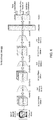
- FIG. 12 shows a block diagram of an exemplary age and gender estimation neural network based on a small-scale CNN module in accordance with some embodiments described herein.
- FIG. 13 shows a block diagram of an exemplary age and gender estimation system based on a small-scale hardware CNN module and a subimage-based technique in accordance with some embodiments described herein.
- FIG. 14 presents a flowchart illustrating an exemplary process for preprocessing an input face image at the input module in FIG. 13 in accordance with some embodiments described herein.
- FIG. 15 shows a block diagram of an exemplary implementation of the small-scale CNN module in FIG. 13 in accordance with some embodiments described herein.
- FIG. 16 shows a block diagram of an exemplary implementation of the merging module and the decision module in FIG. 13 in accordance with some embodiments described herein.
- FIG. 17 presents a flowchart illustrating an exemplary process for performing age and gender estimation using the disclosed age and gender estimation system in accordance with some embodiments described herein.
- FIG. 18 illustrates an exemplary embedded system within which the disclosed subimage-based face-detection system and the subimage-based age-and-gender-estimation system are implemented in accordance with some embodiments described herein.
- image resolution and “image size” are used interchangeably to mean the number of pixels within a given two-dimensional (2D) image.
- the proposed face detection system, technique and architecture can be implemented on a chipset or a SoC that includes such a small-scale low-cost CNN module.
- the proposed face detection system, technique and architecture can be implemented on a HiSilicon Hi3519 SoC (or “Hi3519,” “Hi3519 SoC” hereinafter) developed for smart cameras by HiSilicon Semiconductor Co. Ltd., a subsidiary of Huawei Technologies Co. Ltd.
- Hi3519 SoC includes both a build-in hardware CNN module and a CPU that can execute some simple software CNN functions.
- the proposed age and gender estimation system can first divide a high-resolution input face image into a set of properly sized image patches (also referred to as “subimages”) with judiciously designed overlaps among neighbouring patches. Each of the image patches can then be processed with a small-scale CNN module, such as the built-in CNN module in Hi3519. The outputs corresponding to the set of image patches can be subsequently merged to obtain the output corresponding to the high-resolution input face image, and the merged output can be further processed by subsequent layers in the age and gender estimation system.
- a small-scale CNN module such as the built-in CNN module in Hi3519.
- the proposed age and gender estimation system can be implemented within a low-cost embedded system including at least one small-scale hardware CNN module and integrated with the aforementioned face detection system which is also implemented on the low-cost embedded system.
- the proposed age and gender estimation system can be coupled to the face detection system to perform age and gender estimation on the detected face images generated by the face detection system, wherein both the age and gender estimation system and the face detection system can perform their designated operations using the at least one small-scale CNN module such as Hi3519.
- the proposed age and gender estimation system can perform age and gender estimation on the small-scale CNN module without compromising the accuracy of the age and gender estimation.
- the ability to perform age and gender estimation in-situ within an embedded system based on the captured and detected face images rather than using a separate device, system, or server to perform such operations can significantly reduce operational cost.
- the proposed age and gender estimation system can also be implemented on a low-cost embedded system which does not include a face detection mechanism.
- the low-cost embedded system can directly receive face images from one or more external sources, and subsequently perform dedicated age and gender estimation operations on the received face images using the proposed age and gender estimation system.
- Hi3519 SoC Most existing CNN-based DL architectures and systems are not cost-effective for many embedded system applications. Meanwhile, some low-cost CNN-enabled embedded systems based on low-cost chipsets have started to emerge.
- Hi3519 SoC The cost of Hi3519 SoC is significantly lower than NvidiaTM TK1/TX1 chipsets.
- Hi3519 SoC also includes a built-in hardware CNN module with many promising features. For example, the parameters of the built-in CNN module in Hi3519 SoC are reconfigurable, i.e., users can modify the network architecture and the parameters, which can be pre-trained for different applications. Moreover, this built-in CNN module is quite fast.
- these small-scale low-cost CNN modules such as Hi3519 SoC often have limited capability and a number of constraints.
- the maximum number of pixels in the input image for the embedded CNN module is 1280.
- the input image sizes increase rapidly from one stage to the next in the coarse-to-fine architecture.
- the MTCNN may modify the MTCNN to use smaller input image sizes and downsample the input videos accordingly.
- the quality of the faces in the videos will be significantly degraded, and as a result the face detection performance will suffer greatly.
- the outputs corresponding to the set of subimages can then be merged, and the merged result can be further processed by the next stage.
- the subimage-based CNN system described in the related patent application can be configured to be equivalent to a large-scale CNN that processes the entire input image without partitioning such that the output of the subimage-based CNN system can be exactly identical to the output of the large-scale CNN.
- some embodiments of this patent disclosure make use of the subimage-based CNN system and technique on one or more stages of the cascaded CNN or the MTCNN so that a larger input image to a given stage of the cascaded CNN or the MTCNN can be partitioned into a set of subimages of a smaller size.
- each stage of the cascaded CNN or the MTCNN can use the same small-scale hardware CNN module that is associated with a maximum input image size constraint.
- the proposed face detection technique and system detects those moving areas in each of the video frames/images.
- the proposed face detection technique and system can use a built-in background subtraction module of Hi3519 to detect those moving areas in the video frame.
- the proposed face detection technique and system uses a coarse-to-fine multi-stage CNN to detect most or all faces in the video frame. More specifically, for each stage in the multi-stage CNN which has an input image size constraint, the subimage-based CNN framework can be applied. For example, some embodiments of the proposed face detection technique only need to apply the subimage-based CNN framework to the last stage of a multi-stage CNN framework.
- the proposed face detection technique and system can also identify the facial landmark points of each detected face (such as eyes, noses, and mouths). This information allows the system to track each face, select the best-pose image (also referred to as “the best face”) of each person, e.g., the one that is closest to the front-view, and send the best face to the server for further processing, such as face retrieval.
- the best face also referred to as “the best face”
- face retrieval By transmitting the faces in the video frame, it is not necessary to transmit the entire video frame to the server for some applications, thereby reducing the requirements of the network bandwidth and computational resource of the server.
- the saving can be especially significant for systems which are equipped with a large number of cameras to simultaneously capture multiple channels of video signals in their applications.
- the built-in hardware CNN module within Hi3519 SoC as an example to illustrate some exemplary implementations of the proposed face detection CNN system and technique.
- the proposed face detection CNN system and technique are not limited to a particular chipset or SoC, such as Hi3519 SoC.
- the disclosed face detection system and technique of using small-scale hardware CNN modules to replace larger, more complex CNN modules in some or all stages of the cascaded CNN or the MTCNN can be applied to any small-scale hardware CNN modules or any chipset or SoC that includes embedded small-scale hardware CNN modules.
- the disclosed face detection system and technique can be implemented as a single field programmable gate array (FPGA) module, and integrated within an embedded platform.
- FPGA field programmable gate array
- the subimage-based CNN system described in the related patent application Ser. No. 15/441,194 is constructed based on small-scale low-cost hardware CNN modules.
- This subimage-based CNN system can be implemented in resource-limited systems, such as embedded systems and mobile devices, to allow these systems to perform tasks which would typically require large-scale, high-complexity expensive CNN systems.
- This subimage-based CNN system can also be implemented in existing DL systems to replace large-scale, high-complexity CNN modules to significantly reduce system cost.
- this subimage-based CNN system allows for using low-cost CNN-enabled embedded systems on high-complexity CNN applications, such as processing high-resolution input images which would otherwise not be feasible for resource-limited embedded systems.
- the subimage-based CNN system reuses one or more small-scale hardware CNN modules which are designed to process input images of lower resolutions, such as the built-in hardware CNN module within Hi3519 SoC, so that the subimage-based CNN system can be applied to higher-resolution input images and more challenging tasks which typically require the processing power of expensive and large-scale hardware CNN modules.
- the subimage-based CNN system is a tiered system which is configured to manage a complex task based on a divide-and-conquer approach.
- the subimage-based CNN system is constructed with two or more stages, wherein each of the two or more stages is implemented with either one or more small-scale low-cost hardware CNN modules or with software which operates on low-resolution inputs. As such, each of the two or more stages can have a very low-complexity.
- an original high-resolution input image can be partitioned into a set of subimages of the same size which is much smaller than the size of the original input image, wherein the partition can include properly designed overlaps among adjacent subimages.
- subimages are fed into the first stage of the subimage-based CNN system which includes at least one small-scale low-cost hardware CNN module designed to handle low-resolution input images, and the outputs from the first stage of the processed set of subimages are subsequently merged.
- the set of subimages can be processed by reusing the one or more small-scale hardware CNN modules repeatedly on the set of subimages. In this manner, a high-resolution input image can be processed by the one or more small-scale hardware CNN modules by way of reusing the one or more small-scale hardware CNN modules on the set of subimages.
- the subimage-based CNN system includes provisions to the sizes of the input images and subimages to ensure that the merged result to be substantially or exactly identical to the output of a large-scale high-complexity CNN module that processes the entire high-resolution input image without partition.
- the merged result is processed by the second stage of the subimage-based CNN system, which can also be implemented with one or more small-scale hardware CNN modules or be implemented with software.
- the disclosed CNN system manages high-complexity tasks such as processing high-resolution input images without requiring large-scale, high-complexity, expensive hardware modules, thereby improving trade-off between performance and cost.
- this subimage-based CNN system can be highly applicable to resource-limited embedded systems, such as various surveillance cameras, machine vision cameras, drones, robots, self-driving cars, and mobile phones.
- FIG. 1A shows a block diagram of a small-scale hardware CNN module 100 for processing a low-resolution input image.
- the CNN module 100 is configured to extract features of a resolution-limited input image and make various DL inferences, depending on the applications.
- CNN module 100 includes at least two submodules, denoted as CNN 1 and CNN 2 .
- CNN module 100 is configured to limit the input image 102 size to no more than 1280 pixels, for example, an image resolution of 32 ⁇ 40 pixels. This limitation on the input image sizes also significantly limits the types of applications which are suitable for CNN module 100 .
- FIG. 1B shows a more detailed implementation of hardware CNN module 100 .
- the first submodule CNN 1 in FIG. 1A further includes multiple alternating convolution (CONV) layers, rectified linear unit (ReLU) layers (not shown) and pooling layers coupled in series.
- CONV convolution
- ReLU rectified linear unit
- a set of convolution filters are employed to extract a set of particular features from input image 102 .
- Each of the CONV layers in the submodule CNN 1 is followed by a corresponding ReLU layer (not shown) and pooling layer, such as POOL( 1 ) layer, which is configured to reduce the size of the filtered images generated by the corresponding CONV layer, while preserving some of the extracted features.
- the second submodule CNN 2 in FIG. 1A further includes multiple alternating fully-connected (FC) layers and ReLU layers (not shown) coupled in series.
- FC fully-connected
- ReLU layers (not shown) coupled in series.
- Each of the FC layers, such as FC( 1 ) layer, in the submodule CNN 2 is configured to perform matrix multiplications.
- Each of the FC layers (except for the last FC layer) is followed by a corresponding ReLU layer (not shown).
- each of the ReLU layers in CNN 1 and CNN 2 is configured to provide nonlinear characteristics to the CNN system.
- a decision module (also not shown) is configured to make a prediction based on the output of the last FC layer, thereby generating the output 104 of the CNN module 100 .
- the first submodule CNN 1 includes 1 ⁇ 8 CONV, ReLU, and pooling layers
- the second submodule CNN 2 includes 3 ⁇ 8 fully-connected (FC) layers and ReLU layers.
- the number of convolution filters in each of the CONV layers is at most 50, and only 3 ⁇ 3 filters are allowed.
- the convolution stride is fixed to be 1, and no zero padding is used.
- the pooling layers in CNN 1 can use a max-pooling technique to select the maximum value from each of the 2 ⁇ 2 regions in the filter images. In some embodiments, both max-pooling and average pooling are supported, but the pooling window size is fixed to 2 ⁇ 2, and the stride is fixed to 2. In other words, each of the image width and height is reduced by one half after each pooling layer.
- the maximum input dimension for the first FC layer is 1024, and the number of neurons in the middle FC layers is at most 256.
- the dimension of the CNN module output is at most 256. Due to these constraints, the hardware CNN module within Hi3519 SoC is typically only suitable for performing simple applications such as handwritten digit recognition and license plate recognition. For more challenging applications such as face recognition, directly applying a small-scale CNN module such as CNN module 100 would be infeasible at least because of the following reasons. First, the maximum input resolution of 1280 pixels (such as 40 ⁇ 32) is very restrictive, because a face image down-sampled to this resolution loses too much important facial information. Second, the learning capacity of the small CNN module 100 is also extremely limited.
- FIG. 2A shows a block diagram of a conventional full-image-based CNN system 200 for processing high-resolution input images.
- conventional CNN system 200 can receive an entire high-resolution input image 202 at the first convolution layer CONV( 1 ) and start performing feature extraction operations on the high-resolution input image 202 .
- conventional CNN system 200 can directly process the full high-resolution input image 202 without partitioning the input image.
- conventional CNN system 200 also requires using large-scale expensive chips capable of handling such high-resolution input images, such as aforementioned NvidiaTM chips.
- FIG. 2B shows a block diagram of a subimage-based CNN system 210 .
- a resolution-limited small-scale CNN module such as CNN module 100 described in conjunction with FIGS. 1A and 1B or the hardware CNN module inside Hi3519 SoC can be used as a building block of subimage-based CNN system 210 .
- a small-scale CNN module has a limitation on the maximum input image size, e.g., up to 1280 pixels.
- the CNN system 210 includes an input module 212 which is configured to partition the high-resolution input image 202 into a set of smaller subimages 204 , wherein each of the subimages 204 has a size which is smaller than or equal to the maximum input image size allowed/supported by the small-scale CNN module used as a building block of CNN system 210 .
- input module 212 is configured to partition the high-resolution input image 202 by including properly designed overlaps between the adjacent subimages 204 , as shown in FIG. 2B . Note that the set of four subimages 204 in two rows and two columns with the illustrated gaps and overlaps are shown in FIG. 2B for the convenience of understanding the concept and not meant for representing an actual partition.
- CNN system 210 includes a two-tiered processing structure based on using and/or reusing one or both of the two hardware submodules CNN 1 and CNN 2 of small-scale CNN module 100 described in FIGS. 1A and 1B .
- CNN system 210 also includes a first processing stage 220 , a merging module 222 and a second processing stage 224 .
- first processing stage 220 of CNN system 210 includes at least one CNN 1 processing module, such as CNN 1 module 214 .
- CNN 1 module 214 is implemented by the hardware submodule CNN 1 described in FIGS. 1A and 1B .
- CNN 1 module 214 is implemented by the entire CNN module 100 described in FIGS. 1A and 1B which includes both CNN 1 and CNN 2 submodules. Note that the multiple instances of CNN 1 module 214 shown within the first processing stage 220 represent the same CNN 1 module 214 being used at different times t 1 , t 2 , t 3 , . . . , and t n as indicated for each such instance. Consequently, “CNN 1 214 at t 1 ,” “CNN 1 214 at t 2 ,” “CNN 1 214 at t 3 ,” . . . , and “CNN 1 214 at t n ,” shown in FIG.
- the first processing stage 220 can include additional CNN 1 modules similar to CNN module 214 .
- the first processing stage 220 can include two or more identical CNN 1 modules.
- the second processing stage 224 of CNN system 210 includes at least one CNN 2 module 216 .
- CNN 2 module 216 is implemented by the hardware submodule CNN 2 described in FIGS. 1A and 1B .
- CNN 2 module 216 is implemented by the entire CNN module 100 described in FIGS. 1A and 1B which includes both CNN 1 and CNN 2 submodules.
- CNN 2 module 216 within the second processing stage 224 can be implemented by software instead of hardware.
- single CNN 1 module 214 is used multiple times by sequentially processing the set of subimages 204 , one subimage at a time. That is, each instance of CNN 1 block 214 within the first processing stage 220 of CNN system 210 represents one of the multiple applications of the same CNN 1 module 214 on one of the set of subimages 204 at a different processing time. However, because the processing speed of each subimage 204 by CNN 1 module 214 can be very fast, the overall processing time for processing the set of subimages 204 also can be quite fast.
- the outputs of multiple applications of CNN 1 module 214 contain an array of feature maps 206 corresponding to the set of subimages 204 after multiple layers of convolution, ReLU, and pooling operations.
- FIG. 2B is based on reusing a single hardware CNN 1 module 214 in the first processing stage 220 of CNN system 210
- other embodiments can use additional hardware CNN 1 modules similar or identical to CNN 1 module 214 in the first processing stage 220 of CNN system 210 , so that the set of subimages 204 can be processed in parallel by the multiple hardware CNN 1 modules.
- the actual number of CNN 1 modules used by a given design can be determined based on the trade-off between hardware cost constraint and speed requirement. For example, some variations to CNN system 210 can include 3 to 5 CNN 1 modules in the first processing stage.
- CNN 1 module 214 can be implemented by either a dedicated hardware submodule CNN 1 such as those described in conjunction with FIGS. 1A and 1B or by the entire CNN module 100 described in conjunction with FIGS. 1A and 1B which includes both CNN 1 and CNN 2 submodules.
- CNN 1 module 214 within CNN system 210 can include only CONV, ReLU, and pooling layers.
- implementing CNN 1 module 214 in CNN system 210 further includes bypassing the FC layers and the corresponding ReLU layers, i.e., bypassing the submodule CNN 2 within CNN module 100 .
- the CNN 1 module 214 When bypassing the CNN 2 submodule, it is necessary for the CNN 1 module 214 to preserve the spatial location information in its output feature maps, because the outputs from the CNN 1 module 214 will be merged for further processing.
- the parameters of the built-in CNN module are reconfigurable. Using this property, bypassing the submodule CNN 2 when such a built-in hardware CNN module is used can be achieved by forcing each of the FC layers within CNN module 100 to be an identity matrix, so that the output from each of the FC layer is simply a reorganization of the two-dimensional feature maps into a one-dimensional vector.
- the ReLU layer after each FC layer can be applied as usual. In a partition embodiment, for a three FC-ReLU-layer CNN 2 submodule configuration, the last two ReLU layers do not change any data, because the concatenation of multiple ReLU layers is equivalent to just one ReLU layer.
- the outputs from CNN 1 module 214 containing the array of feature maps 206 become the inputs to merging module 222 which is configured to merge the array of feature maps 206 to form the full feature maps of the entire input image 202 .
- the merged feature maps can then be used as the inputs to the second processing stage 224 of CNN system 210 .
- the output 228 from the second processing stage 224 is the output from the last FC layer of CNN 2 module 216 .
- output 228 is identical to the output 226 of the conventional CNN system 200 in FIG. 2A .
- the array of feature maps 206 includes a set of three-dimensional (3D) matrices (i.e., two dimensions for a given feature map and one dimension for the number of feature maps).
- the array of feature maps 206 can be composed of nine (i.e., a 3 ⁇ 3 array of) 3D matrices of 2 ⁇ 2 ⁇ 48 sizes, wherein nine is the number of subimages 204 having indices of 0, 1, 2, . . . , 8 (i.e., subimages of 3 rows by 3 columns), 2 ⁇ 2 is the size of a single output feature map after CNN 1 module 214 for each subimage, and 48 is the number of feature maps for each subimage.
- merging module 222 is configured to merge the array of feature maps 206 by concatenating the set of 3D output matrices based on the corresponding indices to form a merged 3D feature-map matrix, while preserving the spatial relationships of the set of subimages 204 .
- this step generates a 3D matrix of 6 ⁇ 6 ⁇ 48.
- the merged 3D matrix can be flattened into a one-dimensional (1D) vector. In the above example, this creates a 1D vector having a size of 1728. Finally, the flattened 1D vector is fed into the second processing stage 224 .
- FIG. 2B shows that the merged feature maps 208 generated by merging module 222 are fed into the second processing stage 224 of CNN system 210 for further processing.
- the second processing stage 224 of CNN system 210 includes at least one CNN 2 module 216 , which further includes a set of FC layers and ReLU layers as described above.
- CNN 2 module 216 in CNN system 210 can be implemented by a dedicated hardware submodule CNN 2 described in conjunction with FIGS. 1A and 1B .
- CNN 2 module 216 within CNN system 210 can include only FC layers and ReLU layers.
- CNN 2 module 216 can be implemented by taking an entire hardware CNN module 100 described in FIGS. 1A and 1B which includes both CNN 1 and CNN 2 submodules.
- implementing CNN 2 module 216 in CNN system 210 further includes bypassing the CONV-ReLU-pooling layers, i.e., bypassing the submodule CNN 1 within CNN module 100 .
- CNN 2 module 216 i.e., the FC layers and ReLU layers can be implemented by software. Because most of the computational complexity of CNN system 210 is in the CONV layers, implementing the FC and ReLU layers in software typically has minor effect on the overall speed of the system.
- systems such as Hi3519 also provide additional tools to optimize the speed of such a software implementation.
- CNN 2 module 216 within the second processing stage 224 can be implemented by software instead of a hardware CNN module.
- most of the computational complexity of CNN system 210 is in the convolution layers implemented by CNN 1 module 214 because the complexity of the FC layers and ReLU layers are generally much lower than the convolution layers.
- the low computational complexity operations implemented by the hardware CNN 2 module 216 in CNN system 210 can be implemented by software in place of hardware CNN 2 or CNN modules mentioned above.
- such a software approach can provide more flexibilities than the embodiments based on the hardware CNN modules.
- the MTCNN has a simpler structure than the cascaded CNN because the MTCNN uses three CNN stages compared to the six stages used by the cascaded CNN. Moreover, the MTCNN can detect the facial landmark locations, which are useful to track a person and decide the pose of each face. Consequently, various examples of the proposed face detection CNN system and technique described below are based on the MTCNN framework which uses three stages. However, it should be noted that the proposed face detection CNN system and technique can also be applied to the cascaded CNN framework.
- Various examples of the proposed face detection CNN system and technique are designed to resolve the above-mentioned conflicts so that the original CNN within each stage of the MTCNN can be implemented with a small-scale low-cost CNN module, such as the built-in CNN module in Hi3519.
- FIG. 3 shows a block diagram of an exemplary face detection system 300 based on a small-scale hardware CNN module in accordance with some embodiments described herein.
- face detection system 300 is implemented on a CNN-enabled embedded system including a small-scale low-cost SoC, such as Hi3519 SoC.
- face detection system 300 receives a video image 302 as input and generates face detection decisions 316 as output.
- input video image 302 is a video frame of a video captured by a camera.
- face detection system 300 includes at least a motion detection module 304 , a pyramid and patch generation module 306 , a first stage CNN 308 , a second stage CNN 310 , a third stage CNN 312 and a final decision module 314 . Face detection system 300 can also include additional modules not shown in FIG. 3 . We now describe each of the blocks in face detection system 300 in more detail.
- input video image 302 is first received by motion detection module 304 .
- motion detection module 304 can be used to locate and identify those areas within each video frame which are associated with motions based on comparisons with previously received video frames.
- these moving areas can include both human objects and non-human objects such as a moving vehicle.
- a moving area can include both the human face and the human body.
- the output from motion detection module 302 includes a set of identified moving areas 318 which can have different sizes. Each identified moving area 318 , which is a portion of the input video image 302 , is then sent to the subsequent face detection modules within face detection system 300 to detect most or all faces within the moving area. In this embodiment, a non-moving area within input video image 302 is typically not considered for face detection. However, some other embodiments of the proposed face detection system can be constructed without a motion detection module.
- motion detection module 302 can be replaced by or combined with a face tracking module (not shown) which is configured to compute the trajectories of detected faces by face detection system 300 . More specifically, a face tracking module can be configured to compute the trajectories based on the face locations in the previous video frames, predict the new locations of the detected faces in a new video frame based on the computed trajectories, and subsequently search these faces in the vicinity of the predicted locations. Note that by combining motion detection and face tracking within face detection system 300 , the face detection speed can be significantly increased.
- the size of a given moving area 318 generated by motion detection module 304 has a minimum value.
- the minimum size of the moving area can be determined based on one or more design parameters as well as the constraints of the small-scale hardware CNN module used in face detection system 300 , such as Hi3519.
- the one or more design parameters include an initial downsampling factor specified for pyramid and patch generation module 306 and a minimum input image size of first stage CNN 308 . For example, if the initial downsampling factor of pyramid and patch generation module 306 is 2:1 and the minimum input image size of first stage CNN 308 is 16 ⁇ 16, the minimum size of a detectable face would be 32 ⁇ 32.
- the minimum size of a detectable face would be 48 ⁇ 48.
- the minimal size of the moving area 318 that is sent to the face detection modules is greater than the minimal detectable face size.
- the maximum size of a moving area generated by motion detection module 304 can be as large as the entire input video image 302 .
- such a moving area can be corresponding to an input image substantially fully occupied by a human face.
- each of the detected moving areas 318 generated by motion detection module 304 (or by a face tracking module, or by a combination of motion detection and face tracking) is processed in a similar manner by the other modules within face detection system 300 , including pyramid and patch generation module 306 , first stage CNN 308 , second stage CNN 310 , the third stage CNN 312 and the final decision module 314 .
- pyramid and patch generation module 306 the operations described below associated with pyramid and patch generation module 306 , first stage CNN 308 , second stage CNN 310 , the third stage CNN 312 and the final decision module 314 are repeated for each of the detected moving areas 318 .
- This process loop over all of the detected moving areas 318 is indicated by a dashed box placed around these modules.
- face detection system 300 is directed to and equally applicable to all of the detected moving areas 318 .
- each detected moving area 318 which is a portion of input video image 302 , is received by pyramid and patch generation module 306 .
- Pyramid and patch generation module 306 is configured to convert moving area 318 into a “pyramid” of multi-resolution representations of moving area 318 by downsampling moving area 318 with different downsampling factors, whereby allowing subsequent face detection modules to detect faces of different scales in moving area 318 . More specifically, a higher-resolution representation of the moving area 318 in the “pyramid” can be used to detect smaller faces in the original input image 302 , while a lower-resolution representation of moving area 318 in the “pyramid” can be used to detect larger faces in the original input image 302 .
- the highest resolution representation of moving area 318 in the pyramid is determined by the input size of first stage CNN 308 and a desired minimum size of the faces that can be detected.
- the input size of first stage CNN 308 can be a user-defined parameter, but the minimum values of the input size are restricted by the minimum input size of first stage CNN 308 , which can be device-specific constraints. For example, for the built-in CNN module in Hi3519 SoC, the minimum input size is 16 ⁇ 16. This constraint dictates that the input size of first stage CNN 308 needs to be at least 16 ⁇ 16.
- the highest resolution representation will also determine the smallest face that can be detected by face detection system 300 .
- the smallest face that can be detected can be determined by multiplying the input size of first stage CNN 308 with the downsampling factor used by pyramid and patch generation module 306 . For example, if 16 ⁇ 16 is used as the input size of first stage CNN 308 , and an initial downsampling factor of 3 is used by pyramid and patch generation module 306 , then the smallest face that can be detected will be 48 ⁇ 48. If an initial downsampling factor of 2 is used by pyramid and patch generation module 306 and 16 ⁇ 16 is used as the input size, then the smallest face that can be detected will be 32 ⁇ 32 instead.
- the initial downsampling factor can be determined as the ratio of the desired minimum size of the faces that can be detected to the input size of first stage CNN 308 . For example, suppose that 16 ⁇ 16 is used as the input size of first stage CNN 308 and the desired minimum size of the faces that can be detected is around 48 ⁇ 48, then an initial downsampling factor of 3 should be used.
- the user-specified input size of first stage CNN 308 can be greater than the minimum input size of first stage CNN 308 , i.e., >16 ⁇ 16.
- the lowest resolution representation of the moving area 318 in the pyramid can be equal or close to but no smaller than the minimum input size of first stage CNN 308 , which is 16 ⁇ 16 in Hi3519.
- the lowest resolution representation of the moving area 318 can be a 24 ⁇ 24 image.
- Other resolution representations of the moving area 318 can be spaced between the lowest and the highest resolution representations in the pyramid, and typically spaced by a factor of 2:1 or 3:1 between the adjacent resolution representations.
- pyramid and patch generation module 306 For each received moving area 318 , pyramid and patch generation module 306 generates a pyramid of multi-resolution representations of this moving area 318 . In other words, pyramid and patch generation module 306 generates a set of images of different resolutions corresponding to the same portion of the original input video image 302 .
- first stage CNN 308 processes image patches based on a user-specified input size as mentioned above. For example, if input size of 16 ⁇ 16 is used, then each image in the pyramid is further partitioned into a set of 16 ⁇ 16 image patches.
- pyramid and patch generation module 306 is configured to partition each image in the pyramid into a set of image patches using a sliding window approach. More specifically, a set of image patches can be generated by stepping a sliding window of user-specified size, e.g., of 16 ⁇ 16 through each image in the pyramid with a user-specified stride, e.g., of 2 or 4 pixels in both row and column directions, such that one image patch is generated at each sliding window location. As a result, pyramid and patch generation module 306 generates and outputs sets of image patches 320 of the same size corresponding to the set of multi-resolution representations of the moving area 318 .
- a sliding window of user-specified size e.g., of 16 ⁇ 16
- stride e.g., of 2 or 4 pixels in both row and column directions
- first stage CNN 308 can process the received image patches 320 in a sequential order one image patch at a time or process multiple image patches in parallel to speed up the processing speed. We now describe some embodiments of first stage CNN 308 in more detail.
- First stage CNN 308 is used to process each received image patch corresponding to each sliding window location within each pyramid representation of the moving area 318 .
- FIG. 4 shows a block diagram of an exemplary implementation 400 of first stage CNN 308 based on a small-scale hardware CNN module in accordance with some embodiments described herein.
- first stage CNN 400 includes two stages of CONV and MP layers (i.e., CONV( 1 )/MP( 1 ) and CONV( 2 )/MP( 2 )), followed by two FC layers (i.e., FC( 1 ) and FC( 2 )).
- each of the CONV and FC layers (except for the last FC layer) is followed by a ReLU layer, which is not shown in FIG. 4 .
- the input to first stage CNN 400 includes 3 R/G/B channels of an input image patch 402 (i.e., one of the sets of image patches 320 in FIG. 3 ), each channel of size 16 ⁇ 16.
- the input to first stage CNN 400 includes a gray-scale image (i.e., a single channel) of an input image patch 402 .
- a gray-scale image i.e., a single channel
- using an associated gray-scale image can entail shorter processing time than using 3 R/G/B channels.
- using the gray-scale image can be advantageous over using 3 R/G/B channels per input image if the performances associated with the two types of inputs are substantially the same.
- CONV( 1 ) layer includes 10 3 ⁇ 3 filters of stride 1.
- the output of CONV( 1 ) layer has a dimension of 14 ⁇ 14 ⁇ 10.
- the MP( 1 ) layer uses 2 ⁇ 2 pooling windows with a stride of 2.
- the output of MP( 1 ) layer has a dimension of 7 ⁇ 7 ⁇ 10.
- the CONV( 2 ) layer includes 16 3 ⁇ 3 filters of stride 1.
- the output of CONV( 2 ) layer has a dimension of 5 ⁇ 5 ⁇ 16.
- the MP( 2 ) layer uses 2 ⁇ 2 pooling windows with a stride 2.
- the output of MP( 2 ) layer has a dimension of 3 ⁇ 3 ⁇ 16.
- the outputs of the first and last FC layers are 32 ⁇ 1 and 16 ⁇ 1 vectors, respectively.
- the first 2 outputs are used to generate the face detection confidence score (also referred as to as “face classifier”); the next 4 outputs are the bounding box coordinates (also referred as to as “bounding box regression operator”) of the face in the image patch 402 (i.e., if a face is detected in the image patch 402 ); and the last 10 outputs indicate the locations of 5 facial landmark points of the detected face, i.e., left eye, right eye, nose, and two corners of the mouth (also referred as to as “landmark localization operator”).
- first stage CNN 400 outputs a set of candidate facial windows/bounding boxes corresponding to a subset of the image patches 320 shown in FIG. 3 .
- first stage CNN 400 is merely one exemplary configuration of first stage CNN 308 .
- Many other configurations of first stage CNN 308 can be constructed which use one or more different parameter values from those shown in FIG. 4 without departing from the scope of the described technology.
- first stage CNN 308 such as the exemplary first stage CNN 400 shown in FIG. 4 is configured to meet the constraints of a small-scale hardware CNN module, such as the built-in hardware CNN module within Hi3519, and therefore can be implemented by the built-in hardware CNN module within Hi3519.
- a filter can be applied to the face detection confidence scores in the detection outputs to only keep those input image patches with face detection confidence scores greater than a threshold values (e.g., a typical threshold value can be set between 0.5 ⁇ 0.7). In some embodiments, this filtering operation is implemented in first stage CNN 308 after the last FC layer.
- NMS non-maximum suppression
- first stage CNN 308 After the NMS operation, the remaining bounding boxes can be refined through a bounding box regression operation to refine the bounding box locations, as also described in the MTCNN. Again, this NMS operation can be implemented in first stage CNN 308 within face detection system 300 . Hence, after one or more additional processing, first stage CNN 308 outputs a set of candidate bounding boxes of faces, or “candidate facial windows.”
- a corresponding image patch is located and cropped from the original input video image 302 , and the cropped image patch is subsequently resized to a user-specified input size of second stage CNN 310 .
- this input size should be larger than the input size of first stage CNN 308 .
- second stage CNN 310 is configured with an input size of 24 ⁇ 24.
- the resized image patches also have the size of 24 ⁇ 24.
- other embodiments of second stage CNN 310 can use similar but slightly different input sizes from 24 ⁇ 24 without departing from the scope of the described technology.
- the process of generating resized image patches from candidate facial windows 322 can be implemented in hardware, in software, or in a combination of hardware and software.
- the corresponding processing module can be positioned between first stage CNN 308 and second stage CNN 310 and is not explicitly shown.
- the resized image patches are received by second stage CNN 310 .
- second stage CNN 310 can process the received resized image patches 324 in a sequential order one image patch at a time or process multiple image patches in parallel to speed up the processing speed. We now describe some embodiments of second stage CNN 310 in more detail.
- FIG. 5 shows a block diagram of an exemplary implementation 500 of second stage CNN 310 based on a small-scale hardware CNN module in accordance with some embodiments described herein.
- second stage CNN 500 includes three stages of CONV and MP layers (i.e., CONV( 1 )/MP( 1 ), CONV( 2 )/MP( 2 ) and CONV( 3 )/MP( 3 )), followed by two FC layers (i.e., FC( 1 ) and FC( 2 )).
- each of the CONV and FC layers is followed by a ReLU layer, which is not shown in FIG. 5 .
- second stage CNN 500 is configured to meet the constraints of the built-in hardware CNN module in Hi3519.
- the input to second stage CNN 500 is a single channel of gray scale image 502 (i.e., one of the resized image patches 324 in FIG. 3 ) of size 24 ⁇ 24 ⁇ 1, instead of an RGB image of size 24 ⁇ 24 ⁇ 3 used in the second stage CNN in MTCNN.
- experimental results show that the performance impact of using gray scale image instead of color image is insignificant.
- second stage CNN 500 can be efficiently implemented by a small-scale hardware CNN such as the embedded CNN within Hi3519.
- CONV( 1 ) layer includes 28 3 ⁇ 3 filters of stride 1.
- the output of CONV( 1 ) layer has a dimension of 22 ⁇ 22 ⁇ 28 (based on the input image size of 24 ⁇ 24).
- the MP( 1 ) layer uses 2 ⁇ 2 pooling windows with a stride of 2.
- the output of MP( 1 ) layer has a dimension of 11 ⁇ 11 ⁇ 28.
- the CONV( 2 ) layer includes 32 3 ⁇ 3 filters of stride 1.
- the output of CONV( 2 ) layer has a dimension of 9 ⁇ 9 ⁇ 32.
- the MP( 2 ) layer uses 2 ⁇ 2 pooling windows with a stride 2.
- the output of MP( 2 ) layer has a dimension of 5 ⁇ 5 ⁇ 32.
- the CONV( 3 ) layer includes 48 3 ⁇ 3 filters of stride 1. Hence, the output of CONV( 3 ) layer has a dimension of 3 ⁇ 3 ⁇ 48.
- the MP( 3 ) layer uses 2 ⁇ 2 pooling windows with a stride 2. Hence, the output of MP( 3 ) layer has a dimension of 2 ⁇ 2 ⁇ 48.
- the outputs of the first and last FC layers are 128 ⁇ 1 and 16 ⁇ 1 vectors, respectively. Note that although each of the CONV layers uses more filters than those used in first stage CNN 400 and the sizes of the FC layers are also bigger than those used in first stage CNN 400 , second stage CNN 500 is still designed to meet the constraints of the built-in CNN module in Hi3519.
- the output of the final FC layer in second stage CNN 500 is still an 16 ⁇ 1 output vector, with the first 2 outputs used to generate the face detection confidence score or face classifier; the next 4 outputs are the bounding box coordinates or the bounding box regression operator of the face in the input image patch 502 (i.e., if a face is detected in the image patch 502 ); and the last 10 outputs indicate the locations of 5 facial landmark points of the detected face, i.e., left eye, right eye, nose, and two corners of the mouth, i.e., landmark localization operator.
- second stage CNN 500 outputs a set of candidate facial windows/bounding boxes (shown as candidate facial windows 326 in FIG. 3 ) corresponding to a subset of the input image patches 502 .
- a confidence score threshold can be applied to the face detection confidence scores in the detection outputs of second stage CNN 310 to only keep those input image patches with face detection confidence scores greater than the threshold value.
- this filtering operation is implemented in second stage CNN 310 after the last FC layer.
- highly overlapped candidate bounding boxes can be merged using the aforementioned NMS technique.
- this NMS operation is also implemented in second stage CNN 310 .
- the locations of the remaining bounding boxes can be refined through a bounding box regression operation, which can be implemented in second stage CNN 310 .
- second stage CNN 310 is configured to meet the constraints of a small-scale hardware CNN module, such as the built-in hardware CNN module within Hi3519, and therefore can be implemented by the built-in hardware CNN module within Hi3519.
- a corresponding image patch is located and cropped from the original input video image 302 , and the cropped image patch is subsequently resized to a user-specified input size of third stage CNN 312 .
- this input size should be larger than the input sizes of both the first and second stage CNNs 308 and 310 .
- third stage CNN 312 is configured with an input size of 46 ⁇ 46.
- the resized image patches also have the size of 46 ⁇ 46.
- other embodiments of third stage CNN 312 can use similar but slightly different input sizes from 46 ⁇ 46 without departing from the scope of the described technology.
- the process of generating resized image patches from the candidate bounding boxes can be implemented in hardware, in software, or in a combination of hardware and software.
- the corresponding processing module can be positioned between second stage CNN 310 and third stage CNN 312 and is not explicitly shown.
- the set resized image patches 328 is received by third stage CNN 312 for final refinement.
- third stage CNN 312 can process the received resized image patches 328 in a sequential order one image patch at a time or process multiple image patches in parallel to speed up the processing speed.
- third stage CNN 312 should process the input image patches 328 in a similar manner as in first stage CNN 308 and second stage CNN 310 .
- FIG. 6 shows a block diagram of an exemplary implementation 600 of third stage CNN 312 in accordance with some embodiments described herein.
- third stage CNN 600 also includes three stages of CONV and MP layers (i.e., CONV( 1 )/MP( 1 ), CONV( 2 )/MP( 2 ) and CONV( 3 )/MP( 3 )), followed by two FC layers (i.e., FC( 1 ) and FC( 2 )).
- CONV( 1 ) layer includes 32 3 ⁇ 3 filters of stride 1.
- the output of CONV( 1 ) layer has a dimension of 44 ⁇ 44 ⁇ 32 (based on the input image size of 46 ⁇ 46).
- the MP( 1 ) layer uses 2 ⁇ 2 pooling windows with a stride of 2.
- the output of MP( 1 ) layer has a dimension of 22 ⁇ 22 ⁇ 32.
- the CONV( 2 ) layer includes 50 3 ⁇ 3 filters of stride 1. Hence, the output of CONV( 2 ) layer has a dimension of 20 ⁇ 20 ⁇ 50.
- the MP( 2 ) layer uses 2 ⁇ 2 pooling windows with a stride 2. Hence, the output of MP( 2 ) layer has a dimension of 10 ⁇ 10 ⁇ 50.
- the CONV( 3 ) layer includes 50 3 ⁇ 3 filters of stride 1. Hence, the output of CONV( 3 ) layer has a dimension of 8 ⁇ 8 ⁇ 50.
- the MP( 3 ) layer uses 2 ⁇ 2 pooling windows with a stride 2. Hence, the output of MP( 3 ) layer has a dimension of 4 ⁇ 4 ⁇ 50.
- the outputs of the first and last FC layers are 256 ⁇ 1 and 16 ⁇ 1 vectors, respectively.
- a CNN module has a maximum input size smaller than 2116 , such a CNN module cannot be configured to implement third stage CNN 600 . Consequently, the embodiment shown in FIG. 6 , while may be useful during the design stage to optimize the network parameters, cannot be implemented with the built-in hardware CNN module in Hi3519 which only supports a maximum input size of 1280 pixels.
- the subimage-based CNN system and technique described in the related patent application can be used. More specifically, using the subimage-based CNN system and technique, the input image patch 602 can be partitioned into a set of overlapping subimages.
- FIG. 7 shows an exemplary input image partition scheme for the 46 ⁇ 46 image patch in accordance with some embodiments described herein. As can be seen on the left side in FIG. 7 , input image patch 602 is partitioned into a set of 4 overlapping subimages or patches, each having a size of 30 ⁇ 30, and a shift or a stride of 16 pixels between neighbouring subimages. Also note that in FIG.
- small artificial offsets are used to slightly shift the four subimages from their overlapping configuration so that they can be better visualized and more easily distinguished from one another.
- these artificial offsets are only used for the purpose of visualizing these overlapping subimages and should not be construed as actual offsets between these subimages in an implementation.
- the row coordinates of these 4 subimages start at 1 and 17, respectively
- the column coordinates of the 4 subimages start at 1 and 17, respectively.
- the set of 4 overlapping subimages without the artificial offsets is shown as a smaller inset to the upper right corner of the main image with the artificial offsets.
- FIG. 8 shows a block diagram of an exemplary implementation 800 of third stage CNN 312 based on a small-scale hardware CNN module in accordance with some embodiments described herein.
- third stage CNN 800 also includes three stages of CONV and MP layers (i.e., CONV( 1 )/MP( 1 ), CONV( 2 )/MP( 2 ) and CONV( 3 )/MP( 3 )) whose parameters are identical to those in the corresponding CONV and MP layers in third stage CNN 600 .
- Third stage CNN 800 also includes an input module 802 which receives the 46 ⁇ 46 input image patch 602 .
- Input module 802 is configured to partition image patch 602 into 4 subimages 804 of size 30 ⁇ 30, which is smaller than the maximum input image size supported by the built-in hardware CNN module in Hi3519. More detailed operation of input module 802 is described in the related patent application Ser. No. 15/441,194 (e.g., input module 212 in FIG. 2B ), the content of which is incorporated herein by reference.
- the three stages of CONV and MP layers in third stage CNN 800 is configured to process the 4 subimages 804 in a sequential manner.
- CONV( 1 ) layer includes 32 3 ⁇ 3 filters of stride 1.
- the output of CONV( 1 ) layer has a dimension of 28 ⁇ 28 ⁇ 32.
- the MP( 1 ) layer uses 2 ⁇ 2 pooling windows with a stride of 2.
- the output of MP( 1 ) layer has a dimension of 14 ⁇ 14 ⁇ 32.
- the CONV( 2 ) layer includes 50 3 ⁇ 3 filters of stride 1.
- the output of CONV( 2 ) layer has a dimension of 12 ⁇ 12 ⁇ 50.
- the MP( 2 ) layer uses 2 ⁇ 2 pooling windows with a stride 2.
- the output of MP( 2 ) layer has a dimension of 6 ⁇ 6 ⁇ 50.
- the CONV( 3 ) layer includes 50 3 ⁇ 3 filters of stride 1.
- the output of CONV( 3 ) layer has a dimension of 4 ⁇ 4 ⁇ 50.
- the MP( 3 ) layer uses 2 ⁇ 2 pooling windows with a stride 2.
- the output of MP( 3 ) layer has a dimension of 2 ⁇ 2 ⁇ 50, i.e., 50 2 ⁇ 2 feature maps 806 .
- MP( 3 ) layer For the set of 4 subimages 804 , MP( 3 ) layer generates outputs of 4 sets of 2 ⁇ 2 ⁇ 50 feature maps 806 .
- third stage CNN 800 also includes a merging module 808 which is configured to receive and merge the 4 sets of 2 ⁇ 2 ⁇ 50 feature maps 806 to form the full feature maps of the full input image patch 602 , i.e., the input to the third stage CNN 800 .
- merging module 808 More detailed operation of merging module 808 is described in the related patent application Ser. No. 15/441,194 (e.g., merging module 222 in FIG. 2B ), the content of which is incorporated herein by reference.
- the output feature maps associated with the set of 4 subimages 804 have no overlap and no gap between adjacent feature maps corresponding to adjacent subimages, and can be merged directly to generate the same output as that of third stage CNN 600 in FIG. 6 before the first FC layer.
- the merged result, i.e., the output of third stage CNN 800 is a set of 50 4 ⁇ 4 feature maps 810 , one of which is also illustrated on the right side in FIG. 7 .
- the built-in hardware CNN in Hi3519 is used to implement the three stages of CONV and MP layers shown in third stage CNN 800 .
- the built-in hardware CNN in Hi3519 also includes at least three FC layers.
- two dummy FC layers configured with the identity matrix as their matrix parameters are included in third stage CNN 800 (not explicitly shown).
- the ReLU layer does not affect the output of the dummy FC layer, because the concatenation of multiple ReLU layers is equivalent to just one ReLU layer.
- third stage CNN 800 does not have to be 46 ⁇ 46.
- Other feasible sizes can be used as the input image size of third stage CNN 800 , and the requirements for the feasible sizes have been described in the related patent application, the content of which is incorporated herein by reference.
- another possible input image size to third stage CNN 800 can be 62 ⁇ 62.
- input image patch 802 can be partitioned into 9 overlapping subimages, each of which has a size of 30 ⁇ 30, and a stride of 16 between neighboring subimages in both horizontal and vertical directions.
- third stage CNN 312 in face detection system 300 is implemented as third stage CNN 800
- third stage CNN 312 outputs the set of 50 4 ⁇ 4 feature maps 810 , which is the input to final decision module 314 .
- final decision module 314 includes multiple FC layers configured to operate on the received feature maps and generate final decisions on the input video image 302 , shown as face detection decisions 316 in FIG. 3 .
- FIG. 9 shows a block diagram of an exemplary implementation 900 of final decision module 314 in accordance with some embodiments described herein.
- the set of 50 4 ⁇ 4 feature maps 810 is received and processed by a reorganization module 902 , which is configured to merge and reorganize of the set of 2D feature maps into a 1D vector of size 800 ⁇ 1.
- the 1D vector is further processed by two stages of FC layers FC( 1 ) and FC( 2 ), which subsequently output face detection decisions 316 for a given detected moving area 318 .
- the final FC layer FC( 2 ) is implemented with a linear classifier such as a softmax classifier.
- face detection decisions 316 can include face classifier 904 , bounding box regression operator 906 ; and facial landmark localization operator 908 .
- landmark localization operator 908 within in face detection decisions 316 can include the locations of 5 facial landmark points of the detected face, i.e., left eye, right eye, nose, and two corners of the mouth.
- the two FC layers within final decision module 900 have sizes of 256 and 16, respectively, other embodiments of final decision module 314 can have FC layer sizes different from those in final decision module 900 .
- final decision module 900 can be implemented in software and processed by the CPU on Hi3519 SoC, because final decision module 900 has much lower computational complex than each of the three stages of the CNNs 308 , 310 , and 312 .
- FIG. 10 presents a flowchart illustrating an exemplary face detection process 1000 using the disclosed face detection system 300 implemented on a CNN-enabled embedded system in accordance with some embodiments described herein.
- the CNN-enabled embedded system includes a small-scale low-cost SoC, such as Hi3519 SoC.
- the face detection process 1000 begins when a video image/frame is received at the input of the disclosed face detection system (step 1002 ).
- the video image is captured by a high-resolution camera, such as a surveillance camera, a machine vision camera, cameras on a self-drive car, or mobile phone cameras.
- a motion detection operation is performed on the input video image/frame to locate and identify a set of moving areas (i.e., image patches within the video frame associated with motions) within the video frame (step 1004 ).
- the motion detection operation is implemented with a built-in background subtraction module within the CNN-enabled embedded system to detect those moving areas in the video image/frame.
- the output from the motion detection operation includes a set of identified moving areas within the video frame.
- the motion detection operation is replaced by or combined with a face tracking operation. Note that by combining motion detection and face tracking in face detection process 1000 , the face detection speed can be significantly increased. In some embodiments, the motion detection operation can be omitted from face detection process 1000 .
- a pyramid generation operation is performed on the detected moving area to generate multi-resolution representations of the detected moving area (step 1006 ). More specifically, a higher-resolution representation of the detected moving area is to be used to detect smaller faces in the original input video image, while a lower-resolution representation of the detected moving area is to be used to detect larger faces in the original input video image.
- a sliding window operation is performed on each image in the multi-resolution representations to generate a set of image patches for the image (step 1008 ).
- the size of the sliding window is determined based on a first input size of a first CNN processing stage configured with a first complexity level.
- the first CNN processing stage is used to process all of the image patches corresponding to each sliding window location within each multi-resolution representation of detected moving area to generate a first set of candidate facial windows (step 1010 ).
- each of the first set of candidate facial windows is associated with a confident score and a set of bounding box coordinates.
- each candidate facial window is also associated with 5 facial landmark points, i.e., left eye, right eye, nose, and two corners of the mouth.
- the first CNN processing stage is configured to meet the constraints of a small-scale hardware CNN module, such as the built-in hardware CNN module within Hi3519, and therefore can be implemented by the built-in hardware CNN module within Hi3519.
- a second CNN processing stage is used to process a first set of resized image patches corresponding to the first set of candidate facial windows to generate a second set of candidate facial windows (step 1012 ).
- the second CNN processing stage is configured with a second complexity level higher than the first complexity level.
- the size of the first set of resized image patches is equal to a second input size of the second CNN processing stage, wherein the second input size is greater than the first input size of the first CNN processing stage.
- the second CNN processing stage processes higher resolution input image patches with higher face detection accuracy than the first CNN processing stage.
- each of the second set of candidate facial windows is associated with a confident score and a set of bounding box coordinates.
- each candidate facial window is also associated with 5 facial landmark points, i.e., left eye, right eye, nose, and two corners of the mouth.
- the second CNN processing stage is configured to meet the constraints of a small-scale hardware CNN module, such as the built-in hardware CNN module within Hi3519, and therefore can be implemented by the built-in hardware CNN module within Hi3519.
- a third CNN processing stage is used to process a second set of resized image patches corresponding to the second set of candidate facial windows to generate a third set of candidate facial windows (step 1014 ).
- the third CNN processing stage is configured with a third complexity level higher than both the first and the second complexity levels.
- the size of the second set of resized image patches is equal to a third input size of the third CNN processing stage, wherein the third input size is greater than both the first and second input sizes of the first and second CNN processing stages.
- each of the third set of candidate facial windows is associated with a confident score and a set of bounding box coordinates.
- each candidate facial window is also associated with 5 facial landmark points, i.e., left eye, right eye, nose, and two corners of the mouth. Note that steps 1006 to 1014 are repeated for each detected moving area within the original input video frame.
- the third CNN processing stage it is desirable to also implement the third CNN processing stage with a small-scale hardware CNN module, such as the built-in hardware CNN module within Hi3519.
- a small-scale hardware CNN module such as the built-in hardware CNN module within Hi3519.
- the input size of the third CNN processing stage is generally greater than the maximum input size of such a small-scale hardware CNN module, a subimage-based CNN approach has to be used.
- FIG. 11 presents a flowchart illustrating an exemplary process 1100 for processing the second set of resized image patches (i.e., step 1014 in process 1000 ) using the disclosed subimage-based CNN system in accordance with some embodiments described herein.
- a given resized image patch is partitioned into a set of subimages of a smaller image size (step 1102 ).
- the set of subimages includes a two-dimensional array of overlapping subimages.
- a 46 ⁇ 46 image patch can be partitioned into a set of 4 overlapping subimages, each having a size of 30 ⁇ 30, and a shift of 16 pixels between neighbouring subimages.
- the size of the subimages is smaller than the maximum input size of the small-scale hardware CNN module, such as the built-in hardware CNN module within Hi3519.
- processing each of the subimages using the small-scale hardware CNN module includes applying multiple stages of CONV layers and MP layers on the subimage.
- the array of feature maps output by the small-scale hardware CNN module is merged into a set of merged feature maps (step 1106 ). More specifically, the set of merged feature maps are identical to the full feature maps for the entire high-resolution resized image patch generated by a large-scale CNN which processes the high-resolution resized image patch as a whole without partitioning the resized image patch.
- the set of merged feature maps are processed by a second CNN module to predict if the resized image patch is a face (step 1108 ).
- processing the set of merged feature maps includes applying multiple stages of FC layers on the set of merged feature maps.
- embodiments of the disclosed face detection system described above are directed to applying the subimage-based CNN technique to the last CNN stage of a cascaded CNN system
- other embodiments of the disclosed face detection system can also apply the subimage-based CNN technique to more than one stage of a cascaded CNN system, e.g., to the last two stages of the cascaded CNN system.
- the abilities to automatically estimate age and gender of people captured in video images can be highly desirable features in many commercial applications, such as in retail, marketing, security surveillance, and social networking.
- a security camera system installed in a retail store can use such features to automatically categorize the customers captured by the security camera based on the estimated gender and age groups to facilitate the retailer to better understand customer types, trends and behaviors.
- CNNs can be applied to the detected face images to perform age and gender estimation.
- Rothe et al. (“Deep expectation of real and apparent age from a single image without facial landmarks,” International Journal of Computer Vision (IJCV), July 2016) uses a 16-layer VGG neural network having 13 CONV layers and 3 FC layers to process input images of 256 ⁇ 256 resolution.
- IJCV International Journal of Computer Vision
- In Levi et al. (“Age and gender classification using convolutional neural networks,” IEEE Conf. on Computer Vision and Pattern Recognition (CVPR) workshops, June 2015), color images of 227 ⁇ 227 resolution are used. More specifically, the network in Levi contains three CONV layers, each followed by a rectified linear operator and a MP layer taking the maximal value of 3 ⁇ 3 regions.
- the first CONV layer contains 96 filters of 3 ⁇ 7 ⁇ 7 pixels
- the second CONV layer contains 256 filters of 96 ⁇ 5 ⁇ 5 pixels
- the third CONV Layer contains 384 filters of 256 ⁇ 3 ⁇ 3 pixels, wherein the first two CONV layers also use a local response normalization layer.
- two FC layers each containing 512 neurons are used, and each of which is followed by a ReLU and a dropout layer.
- a third FC layer is used to map the outputs to the final classes for age or gender classification.
- Mall et al. Apparent age estimation using ensemble of deep learning models,” CVPR 2016
- an ensemble of VGG-based deep learning models is trained, and the outputs of these deep learning models are combined to produce the final estimation.
- the above-described age and gender estimation techniques are generally not suitable for some low-cost embedded systems based on small-scale hardware CNN modules due to the complexities of these techniques. For example, if one attempts to implement one of the above-described age and gender estimation techniques on the built-in CNN module of Hi3519 SoC, a multitude of constraints associated with Hi3519 built-in CNN module have to be taken into account. For example, as mentioned above, the maximum input image size, i.e., the maximum number of input pixels supported by the Hi3519 CNN module is 1280, which can be the result of the hardware configuration constraint of Hi3519.
- constraints associated with the built-in CNN module in Hi3519 as a result of its specific design include, but are not limited to: (1) the width and height in pixels of the input image have to be even numbers; (2) the maximum number of CONV or FC layers is 8; (3) the maximum output dimension of a FC layer is 256; (4) the input dimension for the first FC layer cannot exceed 1024; (5) each of the CONV layers has to be followed by a MP layer; (6) the maximum number of filters in each CONV layer is 50; (7) in each MP layer, the built-in CNN module only supports pooling window size of 2 ⁇ 2 pixels; and (8) the built-in CNN module only supports 3 ⁇ 3 filters in CONV layers.
- age and gender estimation capabilities in these systems to process detected faces in conjunction with the above-described face detection capabilities.
- the ability to perform age and gender estimation in-situ within a surveillance camera system based on the captured and detected face images rather than using a separate server to perform such operations can significantly reduce operational cost.
- original resolution of the detected face images should be used.
- the proposed age and gender estimation system also uses the above-described subimage-based technique according to the divide-and-conquer principle on those detected face images having sizes greater than the maximum number of input pixels supported by a given small-scale CNN module.
- the proposed age and gender estimation system can first divide a high-resolution input face image into a set of properly sized image patches (also referred to as “subimages”) with judiciously designed overlaps among neighbouring patches. Each of the image patches can then be processed with a small-scale CNN module, such as the built-in CNN module in Hi3519.
- the outputs corresponding to the set of image patches can be subsequently merged to obtain the output corresponding to the high-resolution input face image, and the merged output can be further processed by subsequent layers in the age and gender estimation system to generate age and gender classifications for the input face image.
- the proposed age and gender estimation system based on the subimage-based technique can be configured to be equivalent to a large-scale CNN that processes the entire high-resolution input face image without partitioning, and as such the output of the proposed subimage-based CNN system can be exactly identical to the output of the large-scale CNN.
- FIG. 12 shows a block diagram of an exemplary age and gender estimation neural network 1200 based on a small-scale CNN module in accordance with some embodiments described herein.
- neural network 1200 receives an input face image 1202 having a size of 46 ⁇ 46 as input.
- input face image 1202 can be represented by either 3 R/G/B channels each of the size of 46 ⁇ 46 or a single gray-scale image/channel of size 46 ⁇ 46.
- Input face image 1202 is then passed through 3 CONV layers (i.e., CONV( 1 )-CONV( 3 )), each of which is followed by a ReLU layer (not shown) and a MP layer (i.e., MP( 1 )-MP( 3 )).
- CONV layers i.e., CONV( 1 )-CONV( 3 )
- ReLU layer not shown
- MP layer i.e., MP( 1 )-MP( 3 )
- each of the CONV layers uses 3 ⁇ 3 filters and each of the MP layers
- an FC layer i.e., FC( 1 )
- an output layer based on a softmax classifier i.e., SOFTMAX
- the final output layer is shown as a softmax classifier, the final output layer of neural network 1200 can also be implemented using other types of classifiers suitable for deep learning applications.
- the first two outputs of neural network 1200 are for the gender estimation, i.e., male and female probabilities.
- the next 8 outputs of neural network 1200 correspond to the probabilities of up to 8 age groups, e.g., with age ranges of 0-2, 4-6, 8-13, 15-20, 25-32, 38-43, 48-53, 60 and above. Note that in applications where only gender or age group is needed, the neural network 1200 outputs can be simplified to only include the gender outputs or the age group outputs.
- age and gender estimation neural network 1200 can be used to train the network parameters with training face images.
- these network parameters which are optimized through the training process can include the number of filters in each CONV layer, and weights and biases of the filters in each CONV layer, among others.
- the numbers shown in FIG. 12 can represent an exemplary configuration of a trained neural network 1200 .
- CONV( 1 ) layer includes 24 3 ⁇ 3 filters of stride 1.
- the output of CONV( 1 ) layer has a dimension of 44 ⁇ 44 ⁇ 32.
- the MP( 1 ) layer uses 2 ⁇ 2 pooling windows with a stride of 2.
- the output of MP( 1 ) layer has a dimension of 22 ⁇ 22 ⁇ 32.
- the CONV( 2 ) layer includes 48 3 ⁇ 3 filters of stride 1.
- the output of CONV( 2 ) layer has a dimension of 20 ⁇ 20 ⁇ 48.
- the MP( 2 ) layer uses 2 ⁇ 2 pooling windows with a stride 2.
- the output of MP( 2 ) layer has a dimension of 10 ⁇ 10 ⁇ 48.
- the CONV( 3 ) layer includes 48 3 ⁇ 3 filters of stride 1.
- the output of CONV( 3 ) layer has a dimension of 8 ⁇ 8 ⁇ 48.
- the MP( 3 ) layer uses 2 ⁇ 2 pooling windows with a stride 2.
- the output of MP( 3 ) layer has a dimension of 4 ⁇ 4 ⁇ 48. Therefore, the input dimension to FC( 1 ) layer is 768.
- the outputs of the FC( 1 ) layer and the softmax classifier are 256 ⁇ 1 and 10 ⁇ 1 vectors, respectively.
- the above-described network parameters of the trained neural network 1200 meet the constraints of a given small-scale CNN module, such as the CNN module in Hi3519 SoC, so that neural network 1200 can be implemented by the given small-scale CNN module.
- a given small-scale CNN module such as the CNN module in Hi3519 SoC
- other configurations of neural network 1200 can be constructed which use other numbers of CONV/ReLU/MP layers, filters and FC layer sizes different from those of neural network 1200 without departing from the scope of the described technology, so long as a given network configuration meets the constraints of the given small-scale CNN module, such as the one in Hi3519.
- the exemplary configuration of neural network 1200 which directly receives a 46 ⁇ 46 input image 1202 at the first CONV layer, can be used to train the network parameters with 46 ⁇ 46 training images during the design stage of the proposed age and gender estimation CNN system based on a small-scale CNN module.
- the size of input face image 1202 is larger than the maximum number of input pixels supported by the built-in hardware CNN module.
- the exemplary configuration of neural network 1200 cannot be directly implemented on the built-in hardware CNN module in Hi3519 because the size of input image 1202 exceeds the maximum input image size allowed/supported by CONV( 1 ) layer of the CNN module in Hi3519.
- the subimage-based CNN system and technique described in related patent application Ser. No. 15/441,194 can be used. More specifically, using the subimage-based CNN system and technique, the input face image 1202 can be divided into a set of properly sized subimages or image patches with judiciously designed overlaps among neighbouring patches. For a 46 ⁇ 46 input image, a proper partition scheme has been described in conjunction with FIG. 7 . Hence, input face image 1202 can be partitioned into a set of 4 overlapping subimages or image patches, each having a size of 30 ⁇ 30, and a shift or a stride of 16 pixels between neighbouring subimages or image patches.
- the detected face images cropped out of an original video or still image can have many different dimensions and sizes.
- the input face images are square images of the same width and height. While generally speaking the input face images can also include non-square images, the discussion below based on square images can be readily extended to non-square images.
- FIG. 13 shows a block diagram of an exemplary age and gender estimation system 1300 based on a small-scale hardware CNN module and a subimage-based technique in accordance with some embodiments described herein.
- age and gender estimation system 1300 is implemented on a low-cost embedded system including a small-scale CNN module, e.g., by integrating a Hi3519 SoC.
- age and gender estimation system 1300 receives an input face image 1302 as input and generates gender and age/age group classifications 1312 as outputs, i.e., the age and gender estimations for the person corresponding to input face image 1302 .
- input face image 1302 is an output of the above-described face detection system 300 that processes captured video images.
- input face image 1302 can be cropped out of an original video image, such as input video image 302 .
- input face image 1302 can also be an original input image that includes primarily a human face. It is assumed here that input face image 1302 can have a size different from 46 ⁇ 46.
- Age and gender estimation system 1300 includes at least an input module 1304 , a CNN module 1306 , a merging module 1308 and a classification module 1310 .
- Input module 1304 is configured to perform the aforementioned subimage partitions so that input face image 1302 exceeding the maximum input size supported by a small-scale hardware CNN module can be divided into a set of subimages of a size no greater than the maximum input size of the small-scale hardware CNN module, so that the set of subimages can be individually processed by such a small-scale hardware CNN module.
- CNN module 1306 can be implemented with such a small-scale hardware CNN module to process the smaller subimages.
- Merging module 1308 is configured to merge the outputs corresponding to the set of subimages to ensure that the merged result is identical to the result when the entire input face image 1302 is processed as a whole without using the subimage-based technique.
- Decision module 1310 is configured to map the outputs from merging module 1308 to the final classes for age or gender classification.
- Age and gender estimation system 1300 can also include additional modules not shown in FIG. 13 . We now describe each of the blocks in age and gender estimation system 1300 in more detail.
- input module 1304 receives input face image 1302 .
- Input module 1304 is configured to determine if the size of input face image 1302 is smaller than or equal to the maximum input image size of CNN module 1306 . For example, if CNN module 1306 is implemented with the small-scale CNN module in Hi3519, the maximum input image size supported by CNN module 1306 is 1028, and input module 1304 compares the size of the input image 1302 with 1028. In some embodiments, if the size of input face image 1302 is smaller than or equal to the maximum input image size of CNN module 1306 , input module 1304 is configured to pass input face image 1302 directly to CNN module 1306 without performing any subimage operations.
- input module 1304 is configured to resize (e.g., by upsampling) input face image 1302 to a predetermined input image size that meets the subimage partition constraint, and then partitions the resized input image into a set of subimages for subsequently subimage processing.
- predetermined input image size is described in more detail below.
- input module 1304 is further configured to determine if the input image 1302 has dimensions that meet the partition constraint.
- Related patent application Ser. No. 15/441,194, the content of which is incorporated by reference herein, provides descriptions for partition constraint associated with three-CONV-layer/three-MP-layer CNN system.
- the partition constraint should be met by input face image 1302 to ensure that after partitioning the input face image 1302 into a set of subimages, processing the set of subimages, and subsequently merging the processed set of subimages into feature maps of the input face image 1302 , each of the merged feature maps has no gaps or overlaps.
- the partition constraint also ensures that the merged feature maps from the individual feature maps of the set of subimages are equivalent to the feature maps generated when the entire input face image 1302 is processed as a whole without using the subimage-based CNN technique.
- other configurations of CNN module 1306 having different numbers of CONV/MP layers can have different partition constraints.
- the partition constraint for age and gender estimation system 1300 is a predetermined input image dimension that satisfies the general partition constraint for the configuration of CNN module 1306 .
- the partition constraint can be an input image dimension of 46 ⁇ 46 or 62 ⁇ 62.
- the input face image 1302 meets the partition constraint if input face image 1302 also has the dimension of 46 ⁇ 46 or 62 ⁇ 62.
- input module 1304 partitions input face image 1302 into a set of subimages. For example, if the predetermined partition constraint is 46 ⁇ 46, input face image 1302 can be partitioned into 4 subimages of size 30 ⁇ 30 with a shift or a stride of 16 pixels between neighbouring subimages. Note that each of the subimages is smaller than the maximum input image size of the built-in hardware CNN module in Hi3519. As another example, if the predetermined partition constraint is 62 ⁇ 62, input face image 1302 can be partitioned into 9 subimages of size 30 ⁇ 30 with a shift or a stride of 16 pixels between neighbouring subimages.
- input module 1304 determines that input image 1302 does not meet the predetermined partition constraint
- input module 1304 is configured to resize input image 1302 to the predetermined input image dimension. For example, if the predetermined partition constraint is 46 ⁇ 46, then an input image 1302 larger than 46 ⁇ 46 will be downsampled to the size of 46 ⁇ 46, whereas an input image 1302 smaller than 46 ⁇ 46 will be upsampled to the size of 46 ⁇ 46. After resizing the input image 1302 to satisfy of the partition constraint, the resize input image 1302 can be partitioned into subimages accordingly as described above.
- age and gender estimation system 1300 can be configured with multiple predetermined input image sizes satisfying the general partition constraint of the associated CNN module, and each of the multiple predetermined input image sizes is designed for a particular type of application associated with a given face image resolution. For example, if age and gender estimation system 1300 is to be used in an application where the captured face images contain mostly high resolution faces (e.g., for smart phone cameras), a corresponding predetermined input image size in the age and gender estimation system 1300 should also have a higher resolution.
- age and gender estimation system 1300 is to be used in an application where the captured face images contain mostly low resolution faces (e.g., a surveillance camera at a retail store), a corresponding predetermined input image size in the age and gender estimation system 1300 should also have a lower resolution.
- age and gender estimation system 1300 can be designed to have multiple predetermined input image sizes for different types of applications. Next, at the time age and gender estimation system 1300 is used for a given application, a particular predetermined input image size among the multiple predetermined input image sizes can be selected based on the typical face image resolutions associated with the given application.
- FIG. 14 presents a flowchart illustrating an exemplary process 1400 for preprocessing an input face image at the input module 1304 in accordance with some embodiments described herein.
- input module 1304 receives a new input face image 1302 (step 1402 ).
- Input module 1304 subsequently determines if the size of input face image 1302 is smaller than or equal to the maximum input image size of CNN module 1306 (step 1404 ).
- the maximum input image size is the constraint of a small-scale hardware CNN module within CNN module 1306 . If the size of input face image 1302 is smaller than or equal to the maximum input image size, input module 1304 can pass input face image 1302 directly to CNN module 1306 without performing any subimage operations.
- input module 1304 can resize (e.g., by upsampling) input face image 1302 to a predetermined input image size that meets the subimage partition constraint, and then partitions the resized input image into a set of subimages for subsequently subimage processing.
- input module 1304 determines if the input image 1302 has a size that meets a predetermined partition constraint (step 1406 ). Note that here we assume input face image 1302 is a square image so that only the size needs to be checked. In general, an input image 1302 meets a partition constraint only if both its width and height meet the partition constraint. If input module 1304 determines that input image 1302 meets the predetermined partition constraint, input module 1304 partitions input face image 1302 into a set of subimages (step 1408 ) and passes the set of subimages to CNN module 1306 .
- input module 1304 determines that input image 1302 does not meet the predetermined partition constraint, input module 1304 is configured to resize input image 1302 to the predetermined input image size (step 1410 ). For example, if the input image 1302 is larger than the predetermined input image size, input module 1304 downsamples input image 1302 to the predetermined input image size; whereas if the input image 1302 is smaller than the predetermined input image size, input module 1304 upsamples input image 1302 to the predetermined input image size. Input module 1304 then partitions the resized input face image into a set of subimages (step 1412 ) and passes the set of subimages to CNN module 1306 .
- input module 1304 can be implemented in software and processed by the CPU on Hi3519 SoC, because the associated operations have much lower computational complex than the convolution operations.
- FIG. 15 shows a block diagram of an exemplary implementation 1500 of small-scale CNN module 1306 in age and gender estimation system 1300 in accordance with some embodiments described herein.
- small-scale CNN module 1500 has the identical CONV-layer/MP-layer structure and identical corresponding parameters as those in age and gender estimation neural network 1200 before the first FC layer (FC( 1 )).
- FC( 1 ) FC( 1 )
- input module 1304 partitions the 46 ⁇ 46 image into 4 subimages 1504 of size 30 ⁇ 30, which is smaller than the maximum input image size of the built-in hardware CNN module in Hi3519.
- Each 30 ⁇ 30 subimage can then be processed by small-scale CNN module 1500 as shown in FIG. 15 and the set of 4 subimages 1504 can be processed in a sequential manner.
- CONV( 1 ) layer includes 24 3 ⁇ 3 filters of stride 1.
- the output of CONV( 1 ) layer has a dimension of 28 ⁇ 28 ⁇ 24.
- the MP( 1 ) layer uses 2 ⁇ 2 pooling windows with a stride of 2.
- the output of MP( 1 ) layer has a dimension of 14 ⁇ 14 ⁇ 24.
- the CONV( 2 ) layer includes 48 3 ⁇ 3 filters of stride 1.
- the output of CONV( 2 ) layer has a dimension of 12 ⁇ 12 ⁇ 48.
- the MP( 2 ) layer uses 2 ⁇ 2 pooling windows with a stride 2.
- the output of MP( 2 ) layer has a dimension of 6 ⁇ 6 ⁇ 48.
- the CONV( 3 ) layer includes 48 3 ⁇ 3 filters of stride 1.
- the output of CONV( 3 ) layer has a dimension of 4 ⁇ 4 ⁇ 48.
- the MP( 3 ) layer uses 2 ⁇ 2 pooling windows with a stride 2.
- the output of MP( 3 ) layer has a dimension of 2 ⁇ 2 ⁇ 48, i.e., 48 feature maps 1506 of 2 ⁇ 2 resolution.
- MP( 3 ) layer For the set of 4 subimages 1504 , MP( 3 ) layer generates outputs of 4 sets of 48 feature maps 1506 of 2 ⁇ 2 resolution.
- outputs from the four 30 ⁇ 30 subimages have no overlap and no gap between adjacent feature maps corresponding to adjacent subimages, and can be concatenated directly to obtain the same output as that of FIG. 12 (i.e., without partitioning input face image 1302 ) before the FC( 1 ) layer.
- FIG. 16 shows a block diagram of an exemplary implementation 1600 of merging module 1308 and decision module 1310 in age and gender estimation system 1300 in accordance with some embodiments described herein.
- the outputs from each subimage 1504 in FIG. 15 i.e., 48 ⁇ 2 ⁇ 2 feature maps
- the four vectors 1602 from the four subimages are concatenated by concatenation module 1604 to form a one-dimensional (1D) vector 1606 of size 768 ⁇ 1.
- the 1D vector 1606 is further processed by an FC layer 1608 and finally softmax classifier 1610 to generate output age and gender classifications 1312 for a given input face image 1302 .
- the age classification can include 8 age groups: 0-2, 4-6, 8-13, 15-20, 25-32, 38-43, 48-53, 60 and above.
- merging module 1308 and decision module 1310 can be implemented in software and processed by the CPU on Hi3519 SoC, because these operations have much lower computational complex than the convolution operations.
- the operation of merging module 1308 and decision module 1310 can be further accelerated by the Arm NEON instruction set on Hi3519 SoC.
- FC( 1 ) layer 1608 is shown to have a size of 256, other FC( 1 ) sizes can used for the proposed age and gender estimation system 1300 without departing from the scope of the present technique.
- FIG. 17 presents a flowchart illustrating an exemplary process 1700 for performing age and gender estimation using the disclosed age and gender estimation system in accordance with some embodiments described herein.
- the disclosed CNN system partitions an input face image into a set of subimages of a smaller image size (step 1702 ). More specifically, the size of the set of subimages is smaller than the maximum input size supported by the small-scale hardware CNN module within the CNN system.
- the set of subimages are sequentially processed by the small-scale hardware CNN module to generate an array of feature maps (step 1704 ).
- processing each of the subimages using the small-scale hardware CNN module includes applying multiple stages of CONV layers and MP layers on the subimage.
- the array of feature maps output by the small-scale hardware CNN module is merged into a set of merged feature maps (step 1706 ). More specifically, the set of merged feature maps is identical to the full feature maps generated by a large-scale CNN module which processes the entire input face image without partitioning.
- the set of merged feature maps are processed by a classification module to generate age and gender classifications for the person associated with the input face image (step 1708 ).
- processing the set of merged feature maps includes applying one or more FC layers following by a softmax classifier on the set of merged feature maps.
- each input image or resized input image can be divided into 9 overlapping 30 ⁇ 30 subimages, and there is a stride of 16 pixels between neighboring subimages in both horizontal and vertical directions.
- the proposed age and gender estimation technique can be implemented within any embedded system including a resolution-limited small-scale hardware CNN module, and hence is not limited to Hi3519.
- the ability to perform in-situ age and gender estimation on a set of detected face images within an embedded system immediately after performing in-situ face detections on the captured video or still images, rather than using a separate device, system, or server to perform age and gender estimation on the detected face images can significantly reduce operational cost.
- the proposed age and gender estimation system can also be implemented on a low-cost embedded system which does not include a face detection mechanism. In these embodiments, the low-cost embedded system can directly receive face images from one or more external sources, and subsequently perform dedicated age and gender estimation operations on the received face images using the proposed age and gender estimation system.
- the various embodiments of the age and gender estimation system and technique described herein can also be applied to object classifications.
- the input face images become images of various objects to be classified
- the small-scale CNN module was trained based on a set of training object images
- the outputs of the classification system represent predicted objects for each input object image.
- FIG. 18 illustrates an exemplary embedded system 1800 within which the disclosed face-detection system and age-and-gender-estimation system are implemented in accordance with some embodiments described herein.
- Embedded system 1800 can be integrated with or implemented as a surveillance camera system, a machine vision system, a drone, a robot, or a self-driving car.
- embedded system 1800 can include a bus 1802 , a processor 1804 , a memory 1806 , a storage device 1808 , a camera system 1810 , a CNN subsystem 1812 , an output device interface 1814 , and a network interface 1816 .
- Bus 1802 collectively represents all system, peripheral, and chipset buses that communicatively couple the various components of embedded system 1800 .
- bus 1802 communicatively couples processor 1804 with memory 1806 , storage device 1808 , camera system 1810 , CNN subsystem 1812 , output device interface 1814 , and network interface 1816 .
- processor 1804 retrieves instructions to execute and data to process in order to control various components of embedded system 1800 .
- Processor 1804 can include any type of processor, including, but not limited to, a microprocessor, a mainframe computer, a digital signal processor, a personal organizer, a device controller and a computational engine within an appliance, and any other processor now known or later developed.
- processor 1804 can include one or more cores.
- Processor 1804 itself can include a cache that stores code and data for execution by processor 1804 .
- Memory 1806 can include any type of memory that can store code and data for execution by processor 1804 . This includes but not limited to, dynamic random access memory (DRAM), static random access memory (SRAM), flash memory, read only memory (ROM), and any other type of memory now known or later developed.
- DRAM dynamic random access memory
- SRAM static random access memory
- ROM read only memory
- Storage device 1808 can include any type of non-volatile storage device that can be integrated with embedded system 1800 . This includes, but is not limited to, magnetic, optical, and magneto-optical storage devices, as well as storage devices based on flash memory and/or battery-backed up memory.
- Bus 1802 is also coupled to camera system 1810 .
- Camera system 1810 is configured to capture still images and/or video images at predetermined resolutions and couple the captured image or video data to various components within embedded system 1800 via bus 1802 , such as to memory 1806 for buffering and to CNN subsystem 1812 for DL face detection.
- Camera system 1810 can include one or more digital cameras.
- camera system 1810 includes one or more digital cameras equipped with wide-angle lenses.
- the captured images by camera system 1810 can have different resolutions including high-resolutions such as at 1280 ⁇ 720 p, 1920 ⁇ 1080 p or other high resolutions.
- CNN subsystem 1812 further includes a face detection subsystem 1818 and an age and gender estimation subsystem 1820 .
- CNN subsystem 1812 is configured to receive the captured video images, such as captured high-resolution video images via bus 1802 , perform aforementioned face detection operations on the received video images using face detection subsystem 1818 to generate face detection results for the captured video images, and to further perform aforementioned age and gender detection operations on the detected face images using age and gender estimation subsystem 1820 to generate age and gender classifications for the detected face images.
- CNN subsystem 1812 can include one or more small-scale hardware CNN modules.
- CNN subsystem 1812 can include one or more Hi3519 SoCs, each of which includes both a build-in hardware CNN module and a CPU that can execute software CNN functions.
- CNN subsystem 1812 is implemented in accordance with one of the various embodiments of the disclosed face detection system 300 and the disclosed age and gender estimation system 1300 of this disclosure.
- Output device interface 1814 which is also coupled to bus 1802 , enables for example, the display of the results generated by CNN subsystem 1812 .
- Output devices used with output device interface 1814 include, for example, printers and display devices, such as cathode ray tube displays (CRT), light-emitting diode displays (LED), liquid crystal displays (LCD), organic light-emitting diode displays (OLED), plasma displays, or electronic paper.
- printers and display devices such as cathode ray tube displays (CRT), light-emitting diode displays (LED), liquid crystal displays (LCD), organic light-emitting diode displays (OLED), plasma displays, or electronic paper.
- CTR cathode ray tube displays
- LED light-emitting diode displays
- LCD liquid crystal displays
- OLED organic light-emitting diode displays
- plasma displays or electronic paper.
- bus 1802 also couples embedded system 1800 to a network (not shown) through a network interface 1816 .
- embedded system 1800 can be a part of a network (such as a local area network (“LAN”), a wide area network (“WAN”), or an Intranet, or a network of networks, such as the Internet. Any or all components of embedded system 1800 can be used in conjunction with the subject disclosure.
- DSP digital signal processor
- ASIC application specific integrated circuit
- FPGA field programmable gate array
- a general-purpose processor may be a microprocessor, but, in the alternative, the processor may be any conventional processor, controller, microcontroller, or state machine.
- a processor may also be implemented as a combination of receiver devices, e.g., a combination of a DSP and a microprocessor, a plurality of microprocessors, one or more microprocessors in conjunction with a DSP core, or any other such configuration. Alternatively, some steps or methods may be performed by circuitry that is specific to a given function.
- the functions described may be implemented in hardware, software, firmware, or any combination thereof. If implemented in software, the functions may be stored as one or more instructions or code on a non-transitory computer-readable storage medium or non-transitory processor-readable storage medium. The steps of a method or algorithm disclosed herein may be embodied in processor-executable instructions that may reside on a non-transitory computer-readable or processor-readable storage medium. Non-transitory computer-readable or processor-readable storage media may be any storage media that may be accessed by a computer or a processor.
- non-transitory computer-readable or processor-readable storage media may include RAM, ROM, EEPROM, FLASH memory, CD-ROM or other optical disk storage, magnetic disk storage or other magnetic storage devices, or any other medium that may be used to store desired program code in the form of instructions or data structures and that may be accessed by a computer.
- Disk and disc includes compact disc (CD), laser disc, optical disc, digital versatile disc (DVD), floppy disk, and Blu-ray disc where disks usually reproduce data magnetically, while discs reproduce data optically with lasers. Combinations of the above are also included within the scope of non-transitory computer-readable and processor-readable media.
- the operations of a method or algorithm may reside as one or any combination or set of codes and/or instructions on a non-transitory processor-readable storage medium and/or computer-readable storage medium, which may be incorporated into a computer program product.
Landscapes
- Engineering & Computer Science (AREA)
- Theoretical Computer Science (AREA)
- Physics & Mathematics (AREA)
- General Physics & Mathematics (AREA)
- Health & Medical Sciences (AREA)
- General Health & Medical Sciences (AREA)
- Evolutionary Computation (AREA)
- Life Sciences & Earth Sciences (AREA)
- Artificial Intelligence (AREA)
- Biomedical Technology (AREA)
- Data Mining & Analysis (AREA)
- Biophysics (AREA)
- Molecular Biology (AREA)
- Software Systems (AREA)
- Computing Systems (AREA)
- General Engineering & Computer Science (AREA)
- Computer Vision & Pattern Recognition (AREA)
- Multimedia (AREA)
- Mathematical Physics (AREA)
- Computational Linguistics (AREA)
- Oral & Maxillofacial Surgery (AREA)
- Human Computer Interaction (AREA)
- Neurology (AREA)
- Databases & Information Systems (AREA)
- Medical Informatics (AREA)
- Bioinformatics & Cheminformatics (AREA)
- Bioinformatics & Computational Biology (AREA)
- Evolutionary Biology (AREA)
- Biodiversity & Conservation Biology (AREA)
- Image Analysis (AREA)
Abstract
Description
-
- Maximum input image size: as mentioned above, in Hi3519, the maximum number of pixels in the input image supported by Hi3519 is 1280. In contrast, in the original design of the MTCNN, the input image size to the second stage is 24×24×3=1728, and the input image size to the third stage is 48×48×3=6912. Both of input sizes exceed the input image size limit of Hi3519.
- Minimum input image size: in Hi3519, the minimum width or height of an input image is 16 pixels. In contrast, in the original design of the MTCNN, the input image size to the first stage is 12×12, which is too small for Hi3519.
- Number of filters: in the built-in CNN module in Hi3519, the maximum number of filters in each of the convolutional (CONV) layers is 50. In contrast, several CONV layers in the original design of the MTCNN have 64 or 128 filters.
- CNN architecture: in the built-in CNN module in Hi3519, each CONV layer is followed by a Max Pooling (MP) layer. However, the MTCNN usually uses two or three consecutive CONV layers without any MP layers between them.
- Pooling window size: in the built-in CNN module in Hi3519, the MP layer is designed to support pooling window size of 2×2 pixels, whereas in the MTCNN, 3×3 max pooling windows are frequently used.
- CONV layer filter size: in the built-in CNN module in Hi3519, the CONV layers use 3×3 filters, whereas in the MTCNN, the CONV layers usually use 5×5 filters and 2×2 filters.
- Non-linear function: the MTCNN uses parametric rectified linear unit (PReLU) as the non-linear function, whereas the built-in CNN module in Hi3519 uses rectified linear unit (ReLU).
- Fully connected (FC) layer: the first stage of the original design of the MTCNN is a fully convolutional network (FCN) to reduce the running time of the sliding window approach during testing, where there is no FC layer involved. In contrast, Hi3519 requires at least 3 FC layers in a CNN.
Claims (25)
Priority Applications (2)
| Application Number | Priority Date | Filing Date | Title |
|---|---|---|---|
| US15/724,256 US10558908B2 (en) | 2016-11-30 | 2017-10-03 | Age and gender estimation using small-scale convolutional neural network (CNN) modules for embedded systems |
| CN201711118413.XA CN107909026B (en) | 2016-11-30 | 2017-11-10 | Small-scale convolutional neural network based age and/or gender assessment method and system |
Applications Claiming Priority (2)
| Application Number | Priority Date | Filing Date | Title |
|---|---|---|---|
| US201662428497P | 2016-11-30 | 2016-11-30 | |
| US15/724,256 US10558908B2 (en) | 2016-11-30 | 2017-10-03 | Age and gender estimation using small-scale convolutional neural network (CNN) modules for embedded systems |
Publications (2)
| Publication Number | Publication Date |
|---|---|
| US20180150684A1 US20180150684A1 (en) | 2018-05-31 |
| US10558908B2 true US10558908B2 (en) | 2020-02-11 |
Family
ID=62190214
Family Applications (3)
| Application Number | Title | Priority Date | Filing Date |
|---|---|---|---|
| US15/441,194 Active 2037-07-04 US10360494B2 (en) | 2016-11-30 | 2017-02-23 | Convolutional neural network (CNN) system based on resolution-limited small-scale CNN modules |
| US15/657,109 Active US10268947B2 (en) | 2016-11-30 | 2017-07-21 | Face detection using small-scale convolutional neural network (CNN) modules for embedded systems |
| US15/724,256 Active 2038-01-02 US10558908B2 (en) | 2016-11-30 | 2017-10-03 | Age and gender estimation using small-scale convolutional neural network (CNN) modules for embedded systems |
Family Applications Before (2)
| Application Number | Title | Priority Date | Filing Date |
|---|---|---|---|
| US15/441,194 Active 2037-07-04 US10360494B2 (en) | 2016-11-30 | 2017-02-23 | Convolutional neural network (CNN) system based on resolution-limited small-scale CNN modules |
| US15/657,109 Active US10268947B2 (en) | 2016-11-30 | 2017-07-21 | Face detection using small-scale convolutional neural network (CNN) modules for embedded systems |
Country Status (4)
| Country | Link |
|---|---|
| US (3) | US10360494B2 (en) |
| KR (2) | KR20180062423A (en) |
| CA (2) | CA2986860A1 (en) |
| SG (2) | SG10201709943RA (en) |
Cited By (2)
| Publication number | Priority date | Publication date | Assignee | Title |
|---|---|---|---|---|
| US20190087648A1 (en) * | 2017-09-21 | 2019-03-21 | Baidu Online Network Technology (Beijing) Co., Ltd | Method and apparatus for facial recognition |
| CN111027366A (en) * | 2019-04-30 | 2020-04-17 | 徐晶 | Adaptive facial signal processing platform |
Families Citing this family (150)
| Publication number | Priority date | Publication date | Assignee | Title |
|---|---|---|---|---|
| WO2017043002A1 (en) * | 2015-09-11 | 2017-03-16 | 日本電気株式会社 | Object counting device, object counting method, object counting program, and object counting system |
| US10592729B2 (en) * | 2016-01-21 | 2020-03-17 | Samsung Electronics Co., Ltd. | Face detection method and apparatus |
| CN106157307B (en) * | 2016-06-27 | 2018-09-11 | 浙江工商大学 | A kind of monocular image depth estimation method based on multiple dimensioned CNN and continuous CRF |
| US10303977B2 (en) * | 2016-06-28 | 2019-05-28 | Conduent Business Services, Llc | System and method for expanding and training convolutional neural networks for large size input images |
| US10366302B2 (en) * | 2016-10-10 | 2019-07-30 | Gyrfalcon Technology Inc. | Hierarchical category classification scheme using multiple sets of fully-connected networks with a CNN based integrated circuit as feature extractor |
| US10360494B2 (en) * | 2016-11-30 | 2019-07-23 | Altumview Systems Inc. | Convolutional neural network (CNN) system based on resolution-limited small-scale CNN modules |
| CN106778856A (en) * | 2016-12-08 | 2017-05-31 | 深圳大学 | A kind of object identification method and device |
| US10318827B2 (en) | 2016-12-19 | 2019-06-11 | Waymo Llc | Object detection neural networks |
| US10546231B2 (en) * | 2017-01-23 | 2020-01-28 | Fotonation Limited | Method for synthesizing a neural network |
| WO2018152741A1 (en) * | 2017-02-23 | 2018-08-30 | Nokia Technologies Oy | Collaborative activation for deep learning field |
| CN106952269B (en) * | 2017-02-24 | 2019-09-20 | 北京航空航天大学 | The reversible video foreground object sequence detection dividing method of neighbour and system |
| CA3054063A1 (en) * | 2017-03-03 | 2018-09-07 | Pindrop Security, Inc. | Method and apparatus for detecting spoofing conditions |
| CN106683680B (en) * | 2017-03-10 | 2022-03-25 | 百度在线网络技术(北京)有限公司 | Speaker recognition method and device, computer equipment and computer readable medium |
| US10185895B1 (en) * | 2017-03-23 | 2019-01-22 | Gopro, Inc. | Systems and methods for classifying activities captured within images |
| US10496895B2 (en) * | 2017-03-28 | 2019-12-03 | Facebook, Inc. | Generating refined object proposals using deep-learning models |
| US11151992B2 (en) * | 2017-04-06 | 2021-10-19 | AIBrain Corporation | Context aware interactive robot |
| US10963493B1 (en) | 2017-04-06 | 2021-03-30 | AIBrain Corporation | Interactive game with robot system |
| US10929759B2 (en) | 2017-04-06 | 2021-02-23 | AIBrain Corporation | Intelligent robot software platform |
| US10810371B2 (en) | 2017-04-06 | 2020-10-20 | AIBrain Corporation | Adaptive, interactive, and cognitive reasoner of an autonomous robotic system |
| US10839017B2 (en) | 2017-04-06 | 2020-11-17 | AIBrain Corporation | Adaptive, interactive, and cognitive reasoner of an autonomous robotic system utilizing an advanced memory graph structure |
| US10621725B2 (en) * | 2017-04-12 | 2020-04-14 | Here Global B.V. | Small object detection from a large image |
| US10515199B2 (en) * | 2017-04-19 | 2019-12-24 | Qualcomm Incorporated | Systems and methods for facial authentication |
| CN110537369B (en) * | 2017-04-21 | 2021-07-13 | 株式会社半导体能源研究所 | Image processing method and image receiving device |
| CN107124609A (en) * | 2017-04-27 | 2017-09-01 | 京东方科技集团股份有限公司 | A kind of processing system of video image, its processing method and display device |
| US10410314B2 (en) * | 2017-04-27 | 2019-09-10 | Apple Inc. | Systems and methods for crossfading image data |
| US10552663B2 (en) * | 2017-05-02 | 2020-02-04 | Techcyte, Inc. | Machine learning classification and training for digital microscopy cytology images |
| WO2018217280A1 (en) | 2017-05-23 | 2018-11-29 | Walmart Apollo, Llc | Automated inspection system |
| US10282589B2 (en) * | 2017-08-29 | 2019-05-07 | Konica Minolta Laboratory U.S.A., Inc. | Method and system for detection and classification of cells using convolutional neural networks |
| CN107644209A (en) * | 2017-09-21 | 2018-01-30 | 百度在线网络技术(北京)有限公司 | Method for detecting human face and device |
| KR102468729B1 (en) * | 2017-09-29 | 2022-11-21 | 삼성전자주식회사 | Electronic device and object sensing method therof |
| EP3698324B1 (en) * | 2017-10-20 | 2022-09-21 | Toyota Motor Europe | Method and system for processing an image and determining viewpoints of objects |
| CN107742107B (en) * | 2017-10-20 | 2019-03-01 | 北京达佳互联信息技术有限公司 | Facial image classification method, device and server |
| CN108052862B (en) * | 2017-11-09 | 2019-12-06 | 北京达佳互联信息技术有限公司 | Age estimation method and device |
| CN111656367A (en) * | 2017-12-04 | 2020-09-11 | 优创半导体科技有限公司 | System and architecture for neural network accelerator |
| US20190188729A1 (en) * | 2017-12-18 | 2019-06-20 | Beijing Jingdong Shangke Information Technology Co., Ltd. | System and method for detecting counterfeit product based on deep learning |
| TWI649698B (en) * | 2017-12-21 | 2019-02-01 | 財團法人工業技術研究院 | Object detection device, object detection method, and computer readable medium |
| WO2019137997A1 (en) * | 2018-01-10 | 2019-07-18 | Institut de Recherche sur les Cancers de l'Appareil Digestif - IRCAD | Automatic segmentation process of a 3d medical image by several neural networks through structured convolution according to the geometry of the 3d medical image |
| US11448632B2 (en) | 2018-03-19 | 2022-09-20 | Walmart Apollo, Llc | System and method for the determination of produce shelf life |
| WO2019204700A1 (en) * | 2018-04-19 | 2019-10-24 | University Of South Florida | Neonatal pain identification from neonatal facial expressions |
| IT201800003188A1 (en) * | 2018-05-25 | 2019-11-25 | Head counter device and digital image processing method | |
| KR102649930B1 (en) | 2018-06-06 | 2024-03-20 | 코그넥스코오포레이션 | Systems and methods for finding and classifying patterns in images with a vision system |
| CN110581970A (en) * | 2018-06-07 | 2019-12-17 | 北京华泰科捷信息技术股份有限公司 | network video storage device with face recognition and analysis function and method |
| CA3105272A1 (en) * | 2018-06-29 | 2020-01-02 | Wrnch Inc. | Human pose analysis system and method |
| KR101942219B1 (en) | 2018-07-05 | 2019-01-24 | 고재성 | Apparatus and method for waste image identification using convolution neural network |
| KR102570562B1 (en) | 2018-07-16 | 2023-08-24 | 삼성전자주식회사 | Image processing apparatus and operating method for the same |
| KR102108391B1 (en) * | 2018-07-18 | 2020-05-12 | 주식회사 영국전자 | Moving Object Linkage Tracking System and Method Using Multiple Cameras |
| CN109285157A (en) * | 2018-07-24 | 2019-01-29 | 深圳先进技术研究院 | Myocardium of left ventricle dividing method, device and computer readable storage medium |
| WO2020023762A1 (en) | 2018-07-26 | 2020-01-30 | Walmart Apollo, Llc | System and method for produce detection and classification |
| CN109272107A (en) * | 2018-08-10 | 2019-01-25 | 广东工业大学 | A method of improving the number of parameters of deep layer convolutional neural networks |
| US10747989B2 (en) * | 2018-08-21 | 2020-08-18 | Software Ag | Systems and/or methods for accelerating facial feature vector matching with supervised machine learning |
| KR101941994B1 (en) * | 2018-08-24 | 2019-01-24 | 전북대학교산학협력단 | System for pedestrian detection and attribute extraction based on a joint deep network |
| US11579921B2 (en) | 2018-08-29 | 2023-02-14 | Alibaba Group Holding Limited | Method and system for performing parallel computations to generate multiple output feature maps |
| KR102553146B1 (en) | 2018-09-13 | 2023-07-07 | 삼성전자주식회사 | Image processing apparatus and operating method for the same |
| JP6695947B2 (en) * | 2018-09-21 | 2020-05-20 | ソニーセミコンダクタソリューションズ株式会社 | Solid-state imaging system, image processing method and program |
| US11176427B2 (en) | 2018-09-26 | 2021-11-16 | International Business Machines Corporation | Overlapping CNN cache reuse in high resolution and streaming-based deep learning inference engines |
| US10733742B2 (en) | 2018-09-26 | 2020-08-04 | International Business Machines Corporation | Image labeling |
| CN109271957B (en) * | 2018-09-30 | 2020-10-20 | 厦门市巨龙信息科技有限公司 | Face gender identification method and device |
| DE102018216962A1 (en) * | 2018-10-02 | 2020-04-02 | Robert Bosch Gmbh | Process for high-resolution, scalable domain translation |
| KR102108854B1 (en) * | 2018-10-05 | 2020-05-12 | 재단법인대구경북과학기술원 | Real-time object detection method and apparatus by deep learning network model |
| US11205093B2 (en) | 2018-10-11 | 2021-12-21 | Tesla, Inc. | Systems and methods for training machine models with augmented data |
| US11715059B2 (en) | 2018-10-12 | 2023-08-01 | Walmart Apollo, Llc | Systems and methods for condition compliance |
| KR102127369B1 (en) * | 2018-10-17 | 2020-06-26 | 엔에이치엔 주식회사 | Neural network system for detecting Palmprint and method for providing Palmprint-based fortune forecasting service |
| CN111079473B (en) * | 2018-10-19 | 2024-08-02 | 北京奇虎科技有限公司 | Sex identification method, sex identification device, electronic equipment and computer readable storage medium |
| KR102169543B1 (en) * | 2018-11-08 | 2020-10-23 | 주식회사 소이넷 | Method for setting artificial intelligence execution model and system for acceleration a.i execution |
| WO2020106332A1 (en) | 2018-11-20 | 2020-05-28 | Walmart Apollo, Llc | Systems and methods for assessing products |
| KR102092205B1 (en) * | 2018-12-03 | 2020-03-23 | 한국과학기술원 | Image processing method and apparatus for generating super resolution, inverse tone mapping and joint super resolution-inverse tone mapping processed multiple output image |
| KR20200066952A (en) | 2018-12-03 | 2020-06-11 | 삼성전자주식회사 | Method and apparatus for performing dilated convolution operation in neural network |
| US10977548B2 (en) | 2018-12-05 | 2021-04-13 | Bank Of America Corporation | Generation of capsule neural networks for enhancing image processing platforms |
| KR102055645B1 (en) * | 2018-12-07 | 2020-01-22 | 아주대학교산학협력단 | High speed convolution method for deep learning |
| KR102096617B1 (en) * | 2018-12-12 | 2020-04-02 | 충남대학교산학협력단 | Driver drowsiness detection system using image and ppg data based on multimodal deep learning |
| DE102018222202A1 (en) * | 2018-12-18 | 2020-06-18 | Volkswagen Aktiengesellschaft | Method and device for operating a machine learning model |
| CN109726678B (en) * | 2018-12-28 | 2023-02-28 | 深圳市捷顺科技实业股份有限公司 | License plate recognition method and related device |
| CN109711413B (en) * | 2018-12-30 | 2023-04-07 | 陕西师范大学 | Image semantic segmentation method based on deep learning |
| CN109753927A (en) * | 2019-01-02 | 2019-05-14 | 腾讯科技(深圳)有限公司 | A kind of method for detecting human face and device |
| CN109753931A (en) * | 2019-01-04 | 2019-05-14 | 广州广电卓识智能科技有限公司 | Convolutional neural networks training method, system and facial feature points detection method |
| CN109711384A (en) * | 2019-01-09 | 2019-05-03 | 江苏星云网格信息技术有限公司 | A kind of face identification method based on depth convolutional neural networks |
| US11080835B2 (en) | 2019-01-09 | 2021-08-03 | Disney Enterprises, Inc. | Pixel error detection system |
| CN109726703B (en) * | 2019-01-11 | 2021-06-18 | 浙江工业大学 | Face image age identification method based on improved ensemble learning strategy |
| US10402695B1 (en) * | 2019-01-23 | 2019-09-03 | StradVision, Inc. | Learning method and learning device for convolutional neural network using 1×H convolution for image recognition to be used for hardware optimization, and testing method and testing device using the same |
| CN109840489A (en) * | 2019-01-24 | 2019-06-04 | 深圳市云恩科技有限公司 | A kind of ferry pedestrian movement tracing detection system and its detection method |
| CN111488475A (en) | 2019-01-29 | 2020-08-04 | 北京三星通信技术研究有限公司 | Image retrieval method, image retrieval device, electronic equipment and computer-readable storage medium |
| US10915809B2 (en) | 2019-02-04 | 2021-02-09 | Bank Of America Corporation | Neural network image recognition with watermark protection |
| CN109886241A (en) * | 2019-03-05 | 2019-06-14 | 天津工业大学 | Driver fatigue detection based on shot and long term memory network |
| CN109934149B (en) * | 2019-03-06 | 2022-08-09 | 百度在线网络技术(北京)有限公司 | Method and apparatus for outputting information |
| US10872258B2 (en) * | 2019-03-15 | 2020-12-22 | Huawei Technologies Co., Ltd. | Adaptive image cropping for face recognition |
| US11222069B2 (en) * | 2019-03-31 | 2022-01-11 | Cortica Ltd. | Low-power calculation of a signature of a media unit |
| KR102083166B1 (en) * | 2019-04-22 | 2020-03-02 | 한국과학기술원 | Image processing method and apparatus |
| CN110046595B (en) * | 2019-04-23 | 2022-08-09 | 福州大学 | Cascade multi-scale based dense face detection method |
| CN110022466A (en) * | 2019-04-24 | 2019-07-16 | 中科院成都信息技术股份有限公司 | A kind of video analysis platform and its control method based on wisdom big data |
| CN110222566A (en) * | 2019-04-30 | 2019-09-10 | 北京迈格威科技有限公司 | A kind of acquisition methods of face characteristic, device, terminal and storage medium |
| CN110334577B (en) * | 2019-05-05 | 2022-09-16 | 四川盛通智联网络科技有限公司 | Face recognition method based on Haisi security chip |
| CN110135313A (en) * | 2019-05-07 | 2019-08-16 | 西安募格网络科技有限公司 | A kind of Age estimation method based on convolutional neural networks |
| CN110097021B (en) * | 2019-05-10 | 2022-09-06 | 电子科技大学 | MTCNN-based face pose estimation method |
| KR102420104B1 (en) | 2019-05-16 | 2022-07-12 | 삼성전자주식회사 | Image processing apparatus and operating method for the same |
| US10831417B1 (en) * | 2019-06-17 | 2020-11-10 | Kyocera Document Solutions Inc. | Convolutional neural network based copy or print wizard |
| CN112115740B (en) * | 2019-06-19 | 2024-04-09 | 京东科技信息技术有限公司 | Method and apparatus for processing image |
| CN112149449A (en) * | 2019-06-26 | 2020-12-29 | 北京华捷艾米科技有限公司 | Face attribute recognition method and system based on deep learning |
| US10748650B1 (en) * | 2019-07-17 | 2020-08-18 | Richard Ricci | Machine learning of dental images for E-commerce |
| CN110351526A (en) * | 2019-07-23 | 2019-10-18 | 北京中安信合科技有限公司 | A kind of personnel's supervisory systems based on artificial intelligence technology |
| US11113822B2 (en) * | 2019-08-14 | 2021-09-07 | International Business Machines Corporation | Moving object identification from a video stream |
| KR102641117B1 (en) * | 2019-08-26 | 2024-02-27 | 삼성전자주식회사 | Method and apparatus of augmenting image |
| CN110706200B (en) * | 2019-09-02 | 2022-08-05 | 杭州深睿博联科技有限公司 | Data prediction method and device |
| CN110619391B (en) * | 2019-09-19 | 2023-04-18 | 华南理工大学 | Detection model compression method and device and computer readable storage medium |
| KR102095892B1 (en) * | 2019-10-02 | 2020-04-01 | (주)디앤아이파비스 | Method, apparatus and system for determining similarity of patent documents using artificial intelligence model |
| KR102405867B1 (en) * | 2019-10-02 | 2022-06-08 | (주)디앤아이파비스 | Method, apparatus and system for determining importance of patent documents using artificial intelligence model |
| US11568062B2 (en) * | 2019-10-10 | 2023-01-31 | Baidu Usa Llc | Methods to protect neural network models |
| WO2021087334A1 (en) * | 2019-11-01 | 2021-05-06 | Vannevar Labs, Inc. | Neural network-based optical character recognition |
| KR20210062477A (en) | 2019-11-21 | 2021-05-31 | 삼성전자주식회사 | Electronic apparatus and control method thereof |
| CN110929794B (en) * | 2019-11-28 | 2022-12-13 | 哈尔滨工程大学 | Side-scan sonar image classification method based on multi-task learning |
| CN111028177B (en) * | 2019-12-12 | 2023-07-21 | 武汉大学 | Edge-based deep learning image motion blur removing method |
| CN111179175B (en) * | 2019-12-27 | 2023-04-07 | 深圳力维智联技术有限公司 | Image processing method and device based on convolutional neural network and storage medium |
| US11687778B2 (en) | 2020-01-06 | 2023-06-27 | The Research Foundation For The State University Of New York | Fakecatcher: detection of synthetic portrait videos using biological signals |
| CN113111679A (en) * | 2020-01-09 | 2021-07-13 | 北京君正集成电路股份有限公司 | Design method of human-shaped upper half monitoring network structure |
| KR102295202B1 (en) * | 2020-01-31 | 2021-08-27 | 중앙대학교 산학협력단 | Multiple object detection method and apparatus |
| US20210248462A1 (en) * | 2020-02-07 | 2021-08-12 | Nec Laboratories America, Inc. | Interpreting convolutional sequence model by learning local and resolution-controllable prototypes |
| CN111401516B (en) * | 2020-02-21 | 2024-04-26 | 华为云计算技术有限公司 | Searching method for neural network channel parameters and related equipment |
| EP3882921A1 (en) | 2020-03-17 | 2021-09-22 | Shanghai United Imaging Healthcare Co., Ltd. | Systems and methods for medical imaging |
| CN113496775A (en) * | 2020-03-19 | 2021-10-12 | 上海联影医疗科技股份有限公司 | Control method and system of radioactive ray equipment |
| US12056608B2 (en) * | 2020-03-20 | 2024-08-06 | Robert Bosch Gmbh | System and method for distributed neural networks on edge devices |
| US11508143B2 (en) | 2020-04-03 | 2022-11-22 | Disney Enterprises, Inc. | Automated salience assessment of pixel anomalies |
| US11568249B2 (en) | 2020-04-07 | 2023-01-31 | International Business Machines Corporation | Automated decision making for neural architecture search |
| US11386656B2 (en) * | 2020-04-08 | 2022-07-12 | Moxa Inc. | Device and method of handling video content analysis |
| US11379697B2 (en) * | 2020-05-20 | 2022-07-05 | Bank Of America Corporation | Field programmable gate array architecture for image analysis |
| JP2023531265A (en) * | 2020-06-30 | 2023-07-21 | ロレアル | High-Resolution Controllable Face Aging with Spatial Awareness Conditional GANs |
| CN111862030B (en) * | 2020-07-15 | 2024-02-09 | 北京百度网讯科技有限公司 | Face synthetic image detection method and device, electronic equipment and storage medium |
| US20220028088A1 (en) * | 2020-07-23 | 2022-01-27 | Vingroup Joint Stock Company | Multi-scale segmentation system |
| US10902290B1 (en) * | 2020-08-04 | 2021-01-26 | Superb Ai Co., Ltd. | Methods for training auto labeling device and performing auto labeling related to object detection while performing automatic verification by using uncertainty scores and devices using the same |
| US10885387B1 (en) * | 2020-08-04 | 2021-01-05 | SUPERB Al CO., LTD. | Methods for training auto-labeling device and performing auto-labeling by using hybrid classification and devices using the same |
| US10902291B1 (en) * | 2020-08-04 | 2021-01-26 | Superb Ai Co., Ltd. | Methods for training auto labeling device and performing auto labeling related to segmentation while performing automatic verification by using uncertainty scores and devices using the same |
| US11889049B2 (en) | 2020-08-14 | 2024-01-30 | Raytheon Company | Gain map generation with rotation compensation |
| US11563899B2 (en) * | 2020-08-14 | 2023-01-24 | Raytheon Company | Parallelization technique for gain map generation using overlapping sub-images |
| CN112016432A (en) * | 2020-08-24 | 2020-12-01 | 高新兴科技集团股份有限公司 | License plate character recognition method based on deep learning, storage medium and electronic equipment |
| EP4205026A4 (en) | 2020-08-25 | 2024-09-25 | Axon Entpr Inc | Systems and methods for rapid license plate reading |
| CN112035683B (en) * | 2020-09-30 | 2024-10-18 | 北京百度网讯科技有限公司 | User interaction information processing model generation method and user interaction information processing method |
| CN112215245A (en) * | 2020-11-05 | 2021-01-12 | 中国联合网络通信集团有限公司 | Image identification method and device |
| CN112464009A (en) * | 2020-11-17 | 2021-03-09 | 百度(中国)有限公司 | Method and device for generating pairing image, electronic equipment and storage medium |
| CN112580453A (en) * | 2020-12-08 | 2021-03-30 | 成都数之联科技有限公司 | Land use classification method and system based on remote sensing image and deep learning |
| US20240056575A1 (en) * | 2020-12-22 | 2024-02-15 | Intellectual Discovery Co., Ltd. | Deep learning-based image coding method and device |
| US20220198539A1 (en) * | 2020-12-23 | 2022-06-23 | Panasonic Intellectual Property Management Co., Ltd. | Checkout system and checkout method |
| KR20220102420A (en) * | 2021-01-13 | 2022-07-20 | 삼성전자주식회사 | Electronic device for upscailing image and method for controlling the same |
| CN112434678B (en) * | 2021-01-27 | 2021-06-04 | 成都无糖信息技术有限公司 | Face measurement feature space searching system and method based on artificial neural network |
| CN113095251B (en) * | 2021-04-20 | 2022-05-27 | 清华大学深圳国际研究生院 | Human body posture estimation method and system |
| US20220383037A1 (en) * | 2021-05-27 | 2022-12-01 | Adobe Inc. | Extracting attributes from arbitrary digital images utilizing a multi-attribute contrastive classification neural network |
| US12067769B2 (en) * | 2021-06-04 | 2024-08-20 | Apple Inc. | Object recognition |
| CN113392899B (en) * | 2021-06-10 | 2022-05-10 | 电子科技大学 | Image classification method based on binary image classification network |
| US11798117B2 (en) * | 2021-06-16 | 2023-10-24 | Bank Of America Corporation | Systems and methods for intelligent steganographic protection |
| KR102635607B1 (en) * | 2021-11-04 | 2024-02-08 | 중앙대학교 산학협력단 | Method and apparatus for multi-label class classification based on coarse-to-fine convolutional neural network |
| US11527074B1 (en) | 2021-11-24 | 2022-12-13 | Continental Automotive Technologies GmbH | Systems and methods for deep multi-task learning for embedded machine vision applications |
| CN114386578B (en) * | 2022-01-12 | 2024-09-24 | 西安石油大学 | Convolutional neural network method implemented on Hai Si NPU-free hardware |
| CN114973727B (en) * | 2022-08-02 | 2022-09-30 | 成都工业职业技术学院 | Intelligent driving method based on passenger characteristics |
Citations (8)
| Publication number | Priority date | Publication date | Assignee | Title |
|---|---|---|---|---|
| US6990217B1 (en) * | 1999-11-22 | 2006-01-24 | Mitsubishi Electric Research Labs. Inc. | Gender classification with support vector machines |
| US7912246B1 (en) * | 2002-10-28 | 2011-03-22 | Videomining Corporation | Method and system for determining the age category of people based on facial images |
| US20110222724A1 (en) * | 2010-03-15 | 2011-09-15 | Nec Laboratories America, Inc. | Systems and methods for determining personal characteristics |
| US8027521B1 (en) * | 2008-03-25 | 2011-09-27 | Videomining Corporation | Method and system for robust human gender recognition using facial feature localization |
| US8831362B1 (en) * | 2011-08-10 | 2014-09-09 | Google Inc. | Estimating age using multiple classifiers |
| US9311564B2 (en) * | 2012-10-05 | 2016-04-12 | Carnegie Mellon University | Face age-estimation and methods, systems, and software therefor |
| US9626597B2 (en) * | 2013-05-09 | 2017-04-18 | Tencent Technology (Shenzhen) Company Limited | Systems and methods for facial age identification |
| US20190042833A1 (en) * | 2017-08-01 | 2019-02-07 | Apple Inc. | Face detection, pose estimation, and distance from a camera estimation using a single network |
Family Cites Families (41)
| Publication number | Priority date | Publication date | Assignee | Title |
|---|---|---|---|---|
| DE60130742T2 (en) * | 2001-05-28 | 2008-07-17 | Honda Research Institute Europe Gmbh | Pattern recognition with hierarchical networks |
| WO2004055735A1 (en) * | 2002-12-16 | 2004-07-01 | Canon Kabushiki Kaisha | Pattern identification method, device thereof, and program thereof |
| US20050047647A1 (en) * | 2003-06-10 | 2005-03-03 | Ueli Rutishauser | System and method for attentional selection |
| US7219085B2 (en) * | 2003-12-09 | 2007-05-15 | Microsoft Corporation | System and method for accelerating and optimizing the processing of machine learning techniques using a graphics processing unit |
| JP4532915B2 (en) * | 2004-01-29 | 2010-08-25 | キヤノン株式会社 | Pattern recognition learning method, pattern recognition learning device, image input device, computer program, and computer-readable recording medium |
| JP4546157B2 (en) * | 2004-06-03 | 2010-09-15 | キヤノン株式会社 | Information processing method, information processing apparatus, and imaging apparatus |
| US20080292194A1 (en) * | 2005-04-27 | 2008-11-27 | Mark Schmidt | Method and System for Automatic Detection and Segmentation of Tumors and Associated Edema (Swelling) in Magnetic Resonance (Mri) Images |
| US7747070B2 (en) * | 2005-08-31 | 2010-06-29 | Microsoft Corporation | Training convolutional neural networks on graphics processing units |
| WO2008133951A2 (en) * | 2007-04-24 | 2008-11-06 | Massachusetts Institute Of Technology | Method and apparatus for image processing |
| US8135202B2 (en) * | 2008-06-02 | 2012-03-13 | Nec Laboratories America, Inc. | Automated method and system for nuclear analysis of biopsy images |
| AU2011302414A1 (en) * | 2010-09-15 | 2013-05-02 | Identicoin, Inc. | Coin identification method and apparatus |
| US10198689B2 (en) * | 2014-01-30 | 2019-02-05 | Hrl Laboratories, Llc | Method for object detection in digital image and video using spiking neural networks |
| IL231862A (en) * | 2014-04-01 | 2015-04-30 | Superfish Ltd | Neural network image representation |
| US9659341B2 (en) * | 2014-06-25 | 2017-05-23 | Qualcomm Incorporated | Texture pipe as an image processing engine |
| FR3025344B1 (en) * | 2014-08-28 | 2017-11-24 | Commissariat Energie Atomique | NETWORK OF CONVOLUTIONAL NEURONS |
| US10255547B2 (en) * | 2014-12-04 | 2019-04-09 | Nvidia Corporation | Indirectly accessing sample data to perform multi-convolution operations in a parallel processing system |
| US10168785B2 (en) * | 2015-03-03 | 2019-01-01 | Nvidia Corporation | Multi-sensor based user interface |
| US9786036B2 (en) * | 2015-04-28 | 2017-10-10 | Qualcomm Incorporated | Reducing image resolution in deep convolutional networks |
| US9741107B2 (en) * | 2015-06-05 | 2017-08-22 | Sony Corporation | Full reference image quality assessment based on convolutional neural network |
| US10410096B2 (en) * | 2015-07-09 | 2019-09-10 | Qualcomm Incorporated | Context-based priors for object detection in images |
| US9633282B2 (en) * | 2015-07-30 | 2017-04-25 | Xerox Corporation | Cross-trained convolutional neural networks using multimodal images |
| US10204299B2 (en) * | 2015-11-04 | 2019-02-12 | Nec Corporation | Unsupervised matching in fine-grained datasets for single-view object reconstruction |
| US9881234B2 (en) * | 2015-11-25 | 2018-01-30 | Baidu Usa Llc. | Systems and methods for end-to-end object detection |
| US10095957B2 (en) * | 2016-03-15 | 2018-10-09 | Tata Consultancy Services Limited | Method and system for unsupervised word image clustering |
| CN109074473B (en) * | 2016-04-11 | 2020-04-24 | 北京市商汤科技开发有限公司 | Method and system for object tracking |
| US9904871B2 (en) * | 2016-04-14 | 2018-02-27 | Microsoft Technologies Licensing, LLC | Deep convolutional neural network prediction of image professionalism |
| US9953679B1 (en) * | 2016-05-24 | 2018-04-24 | Gopro, Inc. | Systems and methods for generating a time lapse video |
| US20170344876A1 (en) * | 2016-05-31 | 2017-11-30 | Samsung Electronics Co., Ltd. | Efficient sparse parallel winograd-based convolution scheme |
| US10185891B1 (en) * | 2016-07-08 | 2019-01-22 | Gopro, Inc. | Systems and methods for compact convolutional neural networks |
| US10169647B2 (en) * | 2016-07-27 | 2019-01-01 | International Business Machines Corporation | Inferring body position in a scan |
| US20180060719A1 (en) * | 2016-08-29 | 2018-03-01 | International Business Machines Corporation | Scale-space label fusion using two-stage deep neural net |
| US10354362B2 (en) * | 2016-09-08 | 2019-07-16 | Carnegie Mellon University | Methods and software for detecting objects in images using a multiscale fast region-based convolutional neural network |
| US10360494B2 (en) * | 2016-11-30 | 2019-07-23 | Altumview Systems Inc. | Convolutional neural network (CNN) system based on resolution-limited small-scale CNN modules |
| US10467458B2 (en) * | 2017-07-21 | 2019-11-05 | Altumview Systems Inc. | Joint face-detection and head-pose-angle-estimation using small-scale convolutional neural network (CNN) modules for embedded systems |
| US10185895B1 (en) * | 2017-03-23 | 2019-01-22 | Gopro, Inc. | Systems and methods for classifying activities captured within images |
| US20190063932A1 (en) * | 2017-08-28 | 2019-02-28 | Nec Laboratories America, Inc. | Autonomous Vehicle Utilizing Pose Estimation |
| US10282589B2 (en) * | 2017-08-29 | 2019-05-07 | Konica Minolta Laboratory U.S.A., Inc. | Method and system for detection and classification of cells using convolutional neural networks |
| US10366166B2 (en) * | 2017-09-07 | 2019-07-30 | Baidu Usa Llc | Deep compositional frameworks for human-like language acquisition in virtual environments |
| US10671083B2 (en) * | 2017-09-13 | 2020-06-02 | Tusimple, Inc. | Neural network architecture system for deep odometry assisted by static scene optical flow |
| US20190079533A1 (en) * | 2017-09-13 | 2019-03-14 | TuSimple | Neural network architecture method for deep odometry assisted by static scene optical flow |
| US10223610B1 (en) * | 2017-10-15 | 2019-03-05 | International Business Machines Corporation | System and method for detection and classification of findings in images |
-
2017
- 2017-02-23 US US15/441,194 patent/US10360494B2/en active Active
- 2017-07-21 US US15/657,109 patent/US10268947B2/en active Active
- 2017-10-03 US US15/724,256 patent/US10558908B2/en active Active
- 2017-11-28 CA CA2986860A patent/CA2986860A1/en not_active Abandoned
- 2017-11-28 CA CA2986863A patent/CA2986863A1/en not_active Abandoned
- 2017-11-30 KR KR1020170162656A patent/KR20180062423A/en unknown
- 2017-11-30 KR KR1020170162650A patent/KR20180062422A/en unknown
- 2017-11-30 SG SG10201709943RA patent/SG10201709943RA/en unknown
- 2017-11-30 SG SG10201709945UA patent/SG10201709945UA/en unknown
Patent Citations (8)
| Publication number | Priority date | Publication date | Assignee | Title |
|---|---|---|---|---|
| US6990217B1 (en) * | 1999-11-22 | 2006-01-24 | Mitsubishi Electric Research Labs. Inc. | Gender classification with support vector machines |
| US7912246B1 (en) * | 2002-10-28 | 2011-03-22 | Videomining Corporation | Method and system for determining the age category of people based on facial images |
| US8027521B1 (en) * | 2008-03-25 | 2011-09-27 | Videomining Corporation | Method and system for robust human gender recognition using facial feature localization |
| US20110222724A1 (en) * | 2010-03-15 | 2011-09-15 | Nec Laboratories America, Inc. | Systems and methods for determining personal characteristics |
| US8831362B1 (en) * | 2011-08-10 | 2014-09-09 | Google Inc. | Estimating age using multiple classifiers |
| US9311564B2 (en) * | 2012-10-05 | 2016-04-12 | Carnegie Mellon University | Face age-estimation and methods, systems, and software therefor |
| US9626597B2 (en) * | 2013-05-09 | 2017-04-18 | Tencent Technology (Shenzhen) Company Limited | Systems and methods for facial age identification |
| US20190042833A1 (en) * | 2017-08-01 | 2019-02-07 | Apple Inc. | Face detection, pose estimation, and distance from a camera estimation using a single network |
Cited By (4)
| Publication number | Priority date | Publication date | Assignee | Title |
|---|---|---|---|---|
| US20190087648A1 (en) * | 2017-09-21 | 2019-03-21 | Baidu Online Network Technology (Beijing) Co., Ltd | Method and apparatus for facial recognition |
| US10902245B2 (en) * | 2017-09-21 | 2021-01-26 | Baidu Online Network Technology (Beijing) Co., Ltd. | Method and apparatus for facial recognition |
| CN111027366A (en) * | 2019-04-30 | 2020-04-17 | 徐晶 | Adaptive facial signal processing platform |
| CN111027366B (en) * | 2019-04-30 | 2020-11-27 | 六安木子可科技有限公司 | Adaptive facial signal processing platform |
Also Published As
| Publication number | Publication date |
|---|---|
| US10360494B2 (en) | 2019-07-23 |
| SG10201709945UA (en) | 2018-06-28 |
| CA2986863A1 (en) | 2018-05-30 |
| US10268947B2 (en) | 2019-04-23 |
| CA2986860A1 (en) | 2018-05-30 |
| US20180150684A1 (en) | 2018-05-31 |
| US20180150681A1 (en) | 2018-05-31 |
| US20180150740A1 (en) | 2018-05-31 |
| KR20180062423A (en) | 2018-06-08 |
| KR20180062422A (en) | 2018-06-08 |
| SG10201709943RA (en) | 2018-06-28 |
Similar Documents
| Publication | Publication Date | Title |
|---|---|---|
| US10558908B2 (en) | Age and gender estimation using small-scale convolutional neural network (CNN) modules for embedded systems | |
| US10467458B2 (en) | Joint face-detection and head-pose-angle-estimation using small-scale convolutional neural network (CNN) modules for embedded systems | |
| CN107506707B (en) | Face detection using small scale convolutional neural network module in embedded system | |
| CN107909026B (en) | Small-scale convolutional neural network based age and/or gender assessment method and system | |
| CN107895150B (en) | Human face detection and head attitude angle evaluation based on embedded system small-scale convolution neural network module | |
| US11361546B2 (en) | Action recognition in videos using 3D spatio-temporal convolutional neural networks | |
| Wang et al. | A self-training approach for point-supervised object detection and counting in crowds | |
| EP3979200A1 (en) | Video target tracking method and apparatus, computer device and storage medium | |
| US10489634B2 (en) | Image processing | |
| US20180114071A1 (en) | Method for analysing media content | |
| US20190073553A1 (en) | Region proposal for image regions that include objects of interest using feature maps from multiple layers of a convolutional neural network model | |
| WO2018176186A1 (en) | Semantic image segmentation using gated dense pyramid blocks | |
| US10242294B2 (en) | Target object classification using three-dimensional geometric filtering | |
| Lu et al. | Deep learning methods for human behavior recognition | |
| US20220301317A1 (en) | Method and device for constructing object motion trajectory, and computer storage medium | |
| US11640668B2 (en) | Volumetric sampling with correlative characterization for dense estimation | |
| Dahirou et al. | Motion Detection and Object Detection: Yolo (You Only Look Once) | |
| US20220044053A1 (en) | Semantic image segmentation using gated dense pyramid blocks | |
| Shi et al. | SSFD: A face detector using a single-scale feature map | |
| EP1993060A1 (en) | Device for object detection in an image, and method thereof | |
| US12131541B2 (en) | Method and a system for spatio-temporal polarization video analysis | |
| Jeong et al. | ‘Human activity recognition with computer vision | |
| Trinh et al. | SeaDSC: A video-based unsupervised method for dynamic scene change detection in unmanned surface vehicles | |
| Kumar et al. | DeepMI: A Mutual Information Based Framework For Unsupervised Deep Learning of Tasks | |
| Abutaleb et al. | FPGA-based real-time video-object segmentation with optimization schemes |
Legal Events
| Date | Code | Title | Description |
|---|---|---|---|
| FEPP | Fee payment procedure |
Free format text: ENTITY STATUS SET TO UNDISCOUNTED (ORIGINAL EVENT CODE: BIG.); ENTITY STATUS OF PATENT OWNER: SMALL ENTITY |
|
| FEPP | Fee payment procedure |
Free format text: ENTITY STATUS SET TO SMALL (ORIGINAL EVENT CODE: SMAL); ENTITY STATUS OF PATENT OWNER: SMALL ENTITY |
|
| STPP | Information on status: patent application and granting procedure in general |
Free format text: DOCKETED NEW CASE - READY FOR EXAMINATION |
|
| AS | Assignment |
Owner name: SHENZHEN ALTUMVIEW TECHNOLOGY CO., LTD., CHINA Free format text: ASSIGNMENT OF ASSIGNORS INTEREST;ASSIGNORS:WANG, XING;SEYFI, MEHDI;CHEN, MINGHUA;AND OTHERS;REEL/FRAME:044220/0132 Effective date: 20171012 |
|
| STPP | Information on status: patent application and granting procedure in general |
Free format text: NON FINAL ACTION MAILED |
|
| AS | Assignment |
Owner name: ALTUMVIEW SYSTEMS INC., CANADA Free format text: ASSIGNMENT OF ASSIGNORS INTEREST;ASSIGNOR:SHENZHEN ALTUMVIEW TECHNOLOGY CO., LTD.;REEL/FRAME:049559/0747 Effective date: 20190226 |
|
| STPP | Information on status: patent application and granting procedure in general |
Free format text: NOTICE OF ALLOWANCE MAILED -- APPLICATION RECEIVED IN OFFICE OF PUBLICATIONS |
|
| STPP | Information on status: patent application and granting procedure in general |
Free format text: PUBLICATIONS -- ISSUE FEE PAYMENT VERIFIED |
|
| STCF | Information on status: patent grant |
Free format text: PATENTED CASE |
|
| FEPP | Fee payment procedure |
Free format text: MAINTENANCE FEE REMINDER MAILED (ORIGINAL EVENT CODE: REM.); ENTITY STATUS OF PATENT OWNER: SMALL ENTITY |
|
| FEPP | Fee payment procedure |
Free format text: SURCHARGE FOR LATE PAYMENT, SMALL ENTITY (ORIGINAL EVENT CODE: M2554); ENTITY STATUS OF PATENT OWNER: SMALL ENTITY |
|
| MAFP | Maintenance fee payment |
Free format text: PAYMENT OF MAINTENANCE FEE, 4TH YR, SMALL ENTITY (ORIGINAL EVENT CODE: M2551); ENTITY STATUS OF PATENT OWNER: SMALL ENTITY Year of fee payment: 4 |