US10557766B2 - Torque sensor for detecting occurrence of metal fatigue in an elastic body - Google Patents
Torque sensor for detecting occurrence of metal fatigue in an elastic body Download PDFInfo
- Publication number
- US10557766B2 US10557766B2 US15/761,713 US201615761713A US10557766B2 US 10557766 B2 US10557766 B2 US 10557766B2 US 201615761713 A US201615761713 A US 201615761713A US 10557766 B2 US10557766 B2 US 10557766B2
- Authority
- US
- United States
- Prior art keywords
- axis
- capacitive element
- torque
- displacement
- annular deformation
- Prior art date
- Legal status (The legal status is an assumption and is not a legal conclusion. Google has not performed a legal analysis and makes no representation as to the accuracy of the status listed.)
- Expired - Fee Related
Links
- 229910052751 metal Inorganic materials 0.000 title description 98
- 239000002184 metal Substances 0.000 title description 98
- 238000001514 detection method Methods 0.000 claims abstract description 425
- 238000006073 displacement reaction Methods 0.000 claims abstract description 367
- 230000005489 elastic deformation Effects 0.000 claims abstract description 30
- 230000002093 peripheral effect Effects 0.000 claims description 63
- 230000009471 action Effects 0.000 claims description 56
- 230000008859 change Effects 0.000 claims description 50
- 239000000463 material Substances 0.000 claims description 27
- 238000003860 storage Methods 0.000 claims description 4
- 230000007257 malfunction Effects 0.000 description 46
- 238000000034 method Methods 0.000 description 27
- 230000035945 sensitivity Effects 0.000 description 26
- 238000003745 diagnosis Methods 0.000 description 23
- BWHMMNNQKKPAPP-UHFFFAOYSA-L potassium carbonate Substances [K+].[K+].[O-]C([O-])=O BWHMMNNQKKPAPP-UHFFFAOYSA-L 0.000 description 19
- 230000007423 decrease Effects 0.000 description 17
- 239000004020 conductor Substances 0.000 description 14
- 239000004283 Sodium sorbate Substances 0.000 description 12
- 239000001095 magnesium carbonate Substances 0.000 description 9
- 238000005259 measurement Methods 0.000 description 9
- 238000009825 accumulation Methods 0.000 description 8
- 239000000470 constituent Substances 0.000 description 7
- 239000004302 potassium sorbate Substances 0.000 description 7
- 230000008569 process Effects 0.000 description 7
- 238000011161 development Methods 0.000 description 6
- 230000018109 developmental process Effects 0.000 description 6
- 238000005304 joining Methods 0.000 description 6
- 239000004303 calcium sorbate Substances 0.000 description 5
- 238000010586 diagram Methods 0.000 description 5
- 238000004519 manufacturing process Methods 0.000 description 5
- 238000012545 processing Methods 0.000 description 5
- 239000001099 ammonium carbonate Substances 0.000 description 4
- 238000013459 approach Methods 0.000 description 4
- 239000011810 insulating material Substances 0.000 description 4
- 238000007747 plating Methods 0.000 description 4
- 229910052782 aluminium Inorganic materials 0.000 description 3
- XAGFODPZIPBFFR-UHFFFAOYSA-N aluminium Chemical compound [Al] XAGFODPZIPBFFR-UHFFFAOYSA-N 0.000 description 3
- 230000012447 hatching Effects 0.000 description 3
- 238000003780 insertion Methods 0.000 description 3
- 230000037431 insertion Effects 0.000 description 3
- 230000007246 mechanism Effects 0.000 description 3
- 230000000149 penetrating effect Effects 0.000 description 3
- 229920005989 resin Polymers 0.000 description 3
- 239000011347 resin Substances 0.000 description 3
- 229910001220 stainless steel Inorganic materials 0.000 description 3
- 239000010935 stainless steel Substances 0.000 description 3
- 230000004323 axial length Effects 0.000 description 2
- 238000006243 chemical reaction Methods 0.000 description 2
- 230000000694 effects Effects 0.000 description 2
- 239000007769 metal material Substances 0.000 description 2
- 230000036544 posture Effects 0.000 description 2
- 229920003002 synthetic resin Polymers 0.000 description 2
- 239000000057 synthetic resin Substances 0.000 description 2
- 238000007740 vapor deposition Methods 0.000 description 2
- 239000011692 calcium ascorbate Substances 0.000 description 1
- 238000005266 casting Methods 0.000 description 1
- 230000005494 condensation Effects 0.000 description 1
- 238000009833 condensation Methods 0.000 description 1
- 238000011109 contamination Methods 0.000 description 1
- 238000005520 cutting process Methods 0.000 description 1
- 238000013461 design Methods 0.000 description 1
- 239000000542 fatty acid esters of ascorbic acid Substances 0.000 description 1
- 230000004907 flux Effects 0.000 description 1
- 238000001746 injection moulding Methods 0.000 description 1
- 238000003825 pressing Methods 0.000 description 1
- PPASLZSBLFJQEF-RKJRWTFHSA-M sodium ascorbate Substances [Na+].OC[C@@H](O)[C@H]1OC(=O)C(O)=C1[O-] PPASLZSBLFJQEF-RKJRWTFHSA-M 0.000 description 1
- 239000007787 solid Substances 0.000 description 1
Images


Classifications
-
- G—PHYSICS
- G01—MEASURING; TESTING
- G01L—MEASURING FORCE, STRESS, TORQUE, WORK, MECHANICAL POWER, MECHANICAL EFFICIENCY, OR FLUID PRESSURE
- G01L3/00—Measuring torque, work, mechanical power, or mechanical efficiency, in general
- G01L3/02—Rotary-transmission dynamometers
- G01L3/04—Rotary-transmission dynamometers wherein the torque-transmitting element comprises a torsionally-flexible shaft
- G01L3/10—Rotary-transmission dynamometers wherein the torque-transmitting element comprises a torsionally-flexible shaft involving electric or magnetic means for indicating
- G01L3/106—Rotary-transmission dynamometers wherein the torque-transmitting element comprises a torsionally-flexible shaft involving electric or magnetic means for indicating involving electrostatic means
-
- G—PHYSICS
- G01—MEASURING; TESTING
- G01L—MEASURING FORCE, STRESS, TORQUE, WORK, MECHANICAL POWER, MECHANICAL EFFICIENCY, OR FLUID PRESSURE
- G01L25/00—Testing or calibrating of apparatus for measuring force, torque, work, mechanical power, or mechanical efficiency
- G01L25/003—Testing or calibrating of apparatus for measuring force, torque, work, mechanical power, or mechanical efficiency for measuring torque
-
- G—PHYSICS
- G01—MEASURING; TESTING
- G01L—MEASURING FORCE, STRESS, TORQUE, WORK, MECHANICAL POWER, MECHANICAL EFFICIENCY, OR FLUID PRESSURE
- G01L3/00—Measuring torque, work, mechanical power, or mechanical efficiency, in general
- G01L3/02—Rotary-transmission dynamometers
- G01L3/14—Rotary-transmission dynamometers wherein the torque-transmitting element is other than a torsionally-flexible shaft
- G01L3/1407—Rotary-transmission dynamometers wherein the torque-transmitting element is other than a torsionally-flexible shaft involving springs
- G01L3/1428—Rotary-transmission dynamometers wherein the torque-transmitting element is other than a torsionally-flexible shaft involving springs using electrical transducers
- G01L3/1442—Rotary-transmission dynamometers wherein the torque-transmitting element is other than a torsionally-flexible shaft involving springs using electrical transducers involving electrostatic means
-
- G—PHYSICS
- G01—MEASURING; TESTING
- G01L—MEASURING FORCE, STRESS, TORQUE, WORK, MECHANICAL POWER, MECHANICAL EFFICIENCY, OR FLUID PRESSURE
- G01L5/00—Apparatus for, or methods of, measuring force, work, mechanical power, or torque, specially adapted for specific purposes
- G01L5/22—Apparatus for, or methods of, measuring force, work, mechanical power, or torque, specially adapted for specific purposes for measuring the force applied to control members, e.g. control members of vehicles, triggers
- G01L5/226—Apparatus for, or methods of, measuring force, work, mechanical power, or torque, specially adapted for specific purposes for measuring the force applied to control members, e.g. control members of vehicles, triggers to manipulators, e.g. the force due to gripping
Definitions
- the present invention relates to a torque sensor, and particularly to a sensor having a function of outputting a torque acting around a predetermined rotation axis as an electric signal.
- Patent Literature 1 discloses a torque sensor of a type in which mechanical deformation caused by action of a torque is detected by a strain gauge.
- Patent Literature 2 discloses a sensor which detects a torque acting on a shaft by forming a magnetostrictive film through plating on a shaft surface and measuring a change in magnetic properties of the magnetostrictive film.
- Patent Literature 3 discloses a torque sensor of a type in which a magnetic force generating part is provided at an end portion of a torsion bar, and a change in magnetic flux density of a magnetic force generated by the magnetic force generating part is detected using a magnetic collecting ring
- Patent Literature 4 discloses a torque sensor of a type in which a large number of magnets are arranged in a cylindrical shape such that N poles and S poles are alternately arranged in the circumferential direction and a magnetic field generated by these magnets is detected.
- Patent Literature 5 discloses a torque sensor in which a link mechanism that deforms a shape of an annular member in a radial direction by action of a torque is prepared and a force applied in the radial direction caused by deformation of the annular member is detected by a load sensor.
- Cited Document 6 discloses a torque sensor of a capacitance type that detects a torque based on a variation amount of a capacitance value of a capacitive element caused by deformation generated in an annular elastic ring by action of a torque.
- a current capacitance type torque sensor is provided with a mechanism including a torque detection portion, a CV conversion circuit, and an electronic circuit including a microcomputer, for example, and is likely to malfunction due to condensation, an impact, an overload, or a contamination that is mixed between a pair of parallel flat plates to provide the capacitance.
- a torque detection portion of the torque sensor has flexibility, and thus, metal fatigue is caused by the overload or a repeated load. As a result, a crack or the like may be generated in an elastic body forming the torque detection portion, and there is a risk that the elastic body may be eventually broken.
- three output signals are compared two by two, and when a difference between output signals of two torque sensors falls within a predetermined range, it is determined that the torque sensors normally function. On the other hand, when the difference does not fall within the predetermined range, it is determined that the torque sensors do not normally function (malfunction).
- Patent Literature 1 JP 2009-058388 A
- Patent Literature 2 JP 2007-024641 A
- Patent Literature 3 JP 2009-244134 A
- Patent Literature 4 JP 2006-292423 A
- Patent Literature 5 JP 2000-019035 A
- Patent Literature 6 JP 2012-037300 A
- an object of the present invention is to provide a torque sensor capable of detecting occurrence of metal fatigue in an elastic body before breakage of the elastic body forming a torque detection portion and diagnosing malfunction of the torque detection portion.
- the present invention provides a torque sensor that detects a torque around a Z axis in an XYZ three-dimensional coordinate system, the torque sensor including: an annular deformation body made of a material elastically deformable by action of a torque to be detected and having a through opening through which the Z axis passes; a first supporting body connected to the annular deformation body at two first portions where the annular deformation body meets an XZ plane; a second supporting body connected to the annular deformation body at two second portions where the annular deformation body includes the Z axis and meets a plane different from the XZ plane, the second supporting body being rotatable around the Z axis with respect to the first supporting body; a displacement electrode that is arranged to the annular deformation body and causes displacement by elastic deformation of the annular deformation body; a fixed electrode arranged at a position opposing the displacement electrode in the first supporting body; and a detection circuit that outputs an electric signal indicating the torque around the Z axis, acting on one of the first
- the first capacitive element is configured of the displacement electrode and the fixed electrode which are arranged at a first position in the high elastic portion where a spacing distance between the annular deformation body and the first supporting body changes when the torque around the Z axis acts
- the second capacitive element is configured of the displacement electrode and the fixed electrode which are arranged at a second position in the low elastic portion where the spacing distance between the annular deformation body and the first supporting body changes when the torque around the Z axis acts
- the detection circuit outputs a first electric signal corresponding to a capacitance value of the first capacitive element and a second electric signal corresponding to a capacitance value of the second capacitive element as electric signals indicating the acting torque, and determines whether the torque sensor functions normally based on a ratio between the first electric signal and the second electric signal.
- a ratio between the first electric signal and the second electric signal changes along with metal fatigue caused first in the low elastic portion than in the high elastic portion. Focusing on this fact, it is possible to provide the torque sensor capable of diagnosing the malfunction of the torque detection portion by detecting that the metal fatigue occurs in the elastic body before breakage of the elastic body forming the torque detection portion.
- Each of the fixed electrodes and the displacement electrodes forming the first and second capacitive elements can be individually formed for each of the capacitive elements.
- one of each fixed electrode and each displacement electrode may be configured of a common electrode. That is, each displacement electrode of the first and second capacitive elements may be configured of the common electrode, or each fixed electrode of the first and second capacitive elements may be configured of the common electrode.
- the area of one of the displacement electrode and the fixed electrode of each of the first and second capacitive elements is set to be larger than the area of the other electrode such that each effective opposing area of each pair of electrodes forming the first and second capacitive elements does not change even when a relative position of the displacement electrode with respect to the fixed electrode changes as a result of action of the torque around the Z axis.
- the effective opposing area of each pair of electrodes forming the first and second capacitive elements does not change even when the torque around the Z axis acts, and thus, it is possible to improve accuracy in torque detection and accuracy in determination on whether the torque sensor functions normally.
- the second supporting body be connected to the annular deformation body in two regions where the annular deformation body meets a YZ plane.
- the deformation of the annular deformation body caused by the acting torque is symmetric with respect to an origin O, and thus, it is easy to measure the torque.
- both the first capacitive element and the second capacitive element are arranged on the V axis or on the W axis as viewed from the Z axis direction.
- the first and second capacitive elements exhibit behavior opposite to each other regarding a change in capacitance value of each capacitive element.
- the present invention provides a torque sensor that detects a torque around a Z axis in an XYZ three-dimensional coordinate system, the torque sensor including: an annular deformation body made of a material elastically deformable by action of a torque to be detected and having a through opening through which the Z axis passes; a first supporting body connected to the annular deformation body at two first portions where the annular deformation body meets an XZ plane; a second supporting body connected to the annular deformation body at two second portions where the annular deformation body includes the Z axis and meets a plane different from the XZ plane, the second supporting body being rotatable around the Z axis with respect to the first supporting body; a displacement electrode that is arranged to the annular deformation body and causes displacement by elastic deformation of the annular deformation body; a fixed electrode arranged at a position opposing the displacement electrode in the first supporting body; and a detection circuit that outputs an electric signal indicating the torque around the Z axis, acting on one of
- the first capacitive element and the second capacitive element are configured of the displacement electrodes and the fixed electrodes which are arranged at two first positions, respectively, in the high elastic portion where a spacing distance between the annular deformation body and the first supporting body changes when the torque around the Z axis acts
- the third capacitive element and the fourth capacitive element are configured of the displacement electrodes and the fixed electrodes which are arranged at two second positions, respectively, in the low elastic portion where the spacing distance between the annular deformation body and the first supporting body changes when the torque around the Z axis acts
- the detection circuit outputs a first electric signal corresponding to a “difference between a capacitance value of the first capacitive element and a capacitance value of the second capacitive element” and a second electric signal corresponding to a “difference between a capacitance value of the third capacitive element and a capacitance value of the fourth capacitive element” as electric signals indicating the acting torque, and determines whether the torque sensor functions normally based on
- a ratio between the first electric signal and the second electric signal changes along with metal fatigue caused first in the low elastic portion than in the high elastic portion.
- the respective fixed electrodes and displacement electrodes forming the first to fourth capacitive elements can be individually formed for each capacitive element.
- one of each fixed electrode and each displacement electrode may be configured of a common electrode. That is, at least two of the respective displacement electrodes of the first to fourth capacitive elements may be configured of the common electrode, or at least two of the respective fixed electrodes of the first to fourth capacitive elements may be configured of the common electrode.
- the area of one of the displacement electrode and the fixed electrode of each of the first to fourth capacitive elements is set to be larger than the area of the other electrode such that each effective opposing area of each pair of electrodes forming the first to fourth capacitive elements does not change even when a relative position of the displacement electrode with respect to the fixed electrode changes as a result of action of the torque around the Z axis.
- the effective opposing area of each pair of electrodes forming the first to fourth capacitive elements does not change even when the torque around the Z axis acts, and thus, it is possible to improve accuracy in torque detection and accuracy in determination on whether the torque sensor functions normally.
- the second supporting body be connected to the annular deformation body in two regions where the annular deformation body meets a YZ plane.
- the deformation of the annular deformation body caused by the acting torque is symmetric with respect to an origin O, and thus, it is easy to measure the torque.
- the first capacitive element is arranged on a positive V axis
- the second capacitive element is arranged on a positive W axis
- the third capacitive element is arranged on a negative V axis
- the fourth capacitive element is arranged on a negative W axis, as viewed from the Z axis direction.
- the first and third capacitive elements exhibit the same behavior with each other, and the second and fourth capacitive elements exhibit the same behavior with each other regarding the change in the capacitance value of each capacitive element.
- it is easy to measure the torque based on the change in the capacitance value of each capacitive element and to perform a process for the malfunction diagnosis of the torque sensor.
- the present invention provides a torque sensor that detects a torque around a Z axis in an XYZ three-dimensional coordinate system, the torque sensor including: an annular deformation body made of a material elastically deformable by action of a torque to be detected and having a through opening through which the Z axis passes; a first supporting body connected to the annular deformation body at two first portions where the annular deformation body meets an XZ plane; a second supporting body connected to the annular deformation body at two second portions where the annular deformation body includes the Z axis and meets a plane different from the XZ plane, the second supporting body being rotatable around the Z axis with respect to the first supporting body; a displacement electrode that is arranged to the annular deformation body and causes displacement by elastic deformation of the annular deformation body; a fixed electrode arranged at a position opposing the displacement electrode in the first supporting body; and a detection circuit that outputs an electric signal indicating the torque around the Z axis, acting on one of
- a ratio between the first electric signal and the second electric signal changes along with metal fatigue caused first in the low elastic portion than in the high elastic portion.
- the respective fixed electrodes and displacement electrodes forming the first to eighth capacitive elements can be individually formed for each capacitive element.
- one of each fixed electrode and each displacement electrode may be configured of a common electrode. That is, at least two of the respective displacement electrodes of the first to eighth capacitive elements may be configured of the common electrode, or at least two of the respective fixed electrodes of the first to eighth capacitive elements may be configured of the common electrode.
- the area of one of the displacement electrode and the fixed electrode of each of the first to eighth capacitive elements is set to be larger than the area of the other electrode such that each effective opposing area of each pair of electrodes forming the first to eighth capacitive elements does not change even when a relative position of the displacement electrode with respect to the fixed electrode changes as a result of action of the torque around the Z axis.
- the effective opposing area of each pair of electrodes forming the first to eighth capacitive elements does not change even when the torque around the Z axis acts, and thus, it is possible to improve accuracy in torque detection and accuracy in determination on whether the torque sensor functions normally.
- the second supporting body be connected to the annular deformation body in two regions where the annular deformation body meets a YZ plane.
- the deformation of the annular deformation body caused by the acting torque is symmetric with respect to an origin O, and thus, it is easy to measure the torque.
- the first high elastic portion is arranged in a region partitioned by a positive X axis and a positive V axis
- the second high elastic portion is arranged in a region defined by a positive Y axis and a positive W axis
- the third high elastic portion is arranged in a region defined by a negative X axis and a negative V axis
- the fourth high elastic portion is arranged in a region defined by a negative Y axis and a negative W axis
- the first low elastic portion is arranged in a region defined by the positive V axis and the positive Y axis
- the second low elastic portion is arranged in a region defined by the positive W axis and the negative X axis
- the third low elastic portion is arranged in a region partitioned by a positive X axis and a positive V axis
- the second high elastic portion is arranged in a region defined by a positive Y axis and a positive W axis
- the first capacitive element and the second capacitive element are arranged symmetrically with respect to the V axis as viewed from the Z axis direction, in the vicinity of the positive V axis, the third capacitive element and the fourth capacitive element are arranged symmetrically with respect to the W axis as viewed from the Z axis direction in the vicinity of the positive W axis, the fifth capacitive element and the sixth capacitive element are arranged symmetrically with respect to the V axis as viewed from the Z axis direction in the vicinity of the negative V axis, and the seventh capacitive element and the eighth capacitive element are arranged symmetrically with respect to the W axis as viewed from the Z axis direction in the vicinity of the negative W axis.
- the first and fifth capacitive elements exhibit the same behavior with each other
- the second and sixth capacitive elements exhibit the same behavior with each other
- the third and seventh capacitive elements exhibit the same behavior with each other
- the fourth and eighth capacitive elements exhibit the same behavior with each other regarding the change in the capacitance value of each capacitive element.
- the high elastic portion and the low elastic portion can be configured in various modes in the above torque sensor.
- the low elastic portion can be configured to be narrower than the high elastic portion in the radial direction of the annular deformation body.
- the low elastic portion can be configured to be thinner than the high elastic portion in the Z axis direction.
- the displacement electrode be arranged on a surface of the annular deformation body, more specifically, on an inner circumferential face, an outer circumferential face, or a surface opposing the first supporting body of the annular deformation body. In this case, it is easy to form the capacitive element between the displacement electrode and the fixed electrode.
- the present invention provides a torque sensor that detects a torque around a Z axis in an XYZ three-dimensional coordinate system, the torque sensor including: an annular deformation body made of a material elastically deformable by action of a torque to be detected and having a through opening through which the Z axis passes; a first supporting body connected to the annular deformation body at two first portions where the annular deformation body meets an XZ plane; a second supporting body connected to the annular deformation body at two second portions where the annular deformation body includes the Z axis and meets a plane different from the XZ plane, the second supporting body being rotatable around the Z axis with respect to the first supporting body; a displacement electrode that is arranged at a predetermined position of the annular deformation body and causes displacement by elastic deformation of the annular deformation body; a fixed electrode arranged at a position opposing the displacement electrode in the first supporting body; and a detection circuit that outputs an electric signal indicating the torque around the Z axis in
- the capacitive element includes a first capacitive element and a second capacitive element.
- Each of the capacitive elements is configured of the displacement electrode and the fixed electrode which are arranged at positions, respectively, corresponding to the displacement portions of the first and second detection portions, and the detection circuit outputs a first electric signal corresponding to a capacitance value of the first capacitive element and a second electric signal corresponding to a capacitance value of the second capacitive element as electric signals indicating the acting torque, and determines whether the torque sensor functions normally based on a ratio between the first electric signal and the second electric signal.
- the metal fatigue is caused in the first and second deformation portions of the second detection portion first and the spring constant thereof decreases as compared to the first and second deformation portions of the first detection portion, and thus, the change occurs in the ratio between the first electric signal and the second electric signal by use for a long period of time.
- the torque sensor capable of detecting that the metal fatigue occurs in the elastic body before breakage of the elastic body forming the torque detection portion and diagnosing the malfunction of the torque detection portion.
- Each of the fixed electrodes and the displacement electrodes forming the first and second capacitive elements can be individually formed for each of the capacitive elements.
- one of each fixed electrode and each displacement electrode may be configured of a common electrode. That is, each displacement electrode of the first and second capacitive elements may be configured of the common electrode, or each fixed electrode of the first and second capacitive elements may be configured of the common electrode.
- the area of one of the displacement electrode and the fixed electrode of each of the first and second capacitive elements is set to be larger than the area of the other electrode such that each effective opposing area of each pair of electrodes forming the first and second capacitive elements does not change even when a relative position of the displacement electrode with respect to the fixed electrode changes as a result of action of the torque around the Z axis.
- the effective opposing area of each pair of electrodes forming the first and second capacitive elements does not change even when the torque around the Z axis acts, and thus, it is possible to improve accuracy in torque detection and accuracy in determination on whether the torque sensor functions normally.
- the second supporting body be connected to the annular deformation body in two regions where the annular deformation body meets the YZ plane.
- the deformation of the annular deformation body caused by the acting torque is symmetric with respect to an origin O, and thus, it is easy to measure the torque.
- the first capacitive element is arranged on a positive V axis
- the second capacitive element is arranged on a positive W axis as viewed from the Z axis direction.
- the first and second capacitive elements exhibit behavior opposite to each other regarding a change in capacitance value of each capacitive element.
- the first and second deformation portions of the first detection portion having a relatively large spring constant and the first and second deformation portions of the second detection portion having a relatively small spring constant can be configured in various modes in each of the above torque sensors.
- the first and second deformation portions of the second detection portion can be configured to be narrower than the first and second deformation portions of the first detection portion in the radial direction of the annular deformation body.
- the first and second deformation portions of the second detection portion can be configured to be thinner than the first and second deformation portions of the first detection portion in the Z axis direction.
- the present invention provides a torque sensor that detects a torque around a Z axis in an XYZ three-dimensional coordinate system, the torque sensor including: an annular deformation body made of a material elastically deformable by action of a torque to be detected and having a through opening through which the Z axis passes; a first supporting body connected to the annular deformation body at two first portions where the annular deformation body meets an XZ plane; a second supporting body connected to the annular deformation body at two second portions where the annular deformation body includes the Z axis and meets a plane different from the XZ plane, the second supporting body being rotatable around the Z axis with respect to the first supporting body; a displacement electrode that is arranged at a predetermined position of the annular deformation body and causes displacement by elastic deformation of the annular deformation body; a fixed electrode arranged at a position opposing the displacement electrode in the first supporting body; and a detection circuit that outputs an electric signal indicating the torque around the Z axis in
- the metal fatigue is caused in the first and second deformation portions of the second and third detection portions first and the spring constant thereof decreases as compared to the first and second deformation portions of the first and fourth detection portions, and thus, the change occurs in the ratio between the first electric signal and the second electric signal by use for a long period of time.
- the torque sensor capable of detecting that the metal fatigue occurs in the elastic body before breakage of the elastic body forming the torque detection portion and diagnosing the malfunction of the torque detection portion.
- the respective fixed electrodes and displacement electrodes forming the first to fourth capacitive elements can be individually formed for each capacitive element.
- one of each fixed electrode and each displacement electrode may be configured of a common electrode. That is, at least two of the respective displacement electrodes of the first to fourth capacitive elements may be configured of the common electrode, or at least two of the respective fixed electrodes of the first to fourth capacitive elements may be configured of the common electrode.
- the area of one of the displacement electrode and the fixed electrode of each of the first to fourth capacitive elements is set to be larger than the area of the other electrode such that each effective opposing area of each pair of electrodes forming the first to fourth capacitive elements does not change even when a relative position of the displacement electrode with respect to the fixed electrode changes as a result of action of the torque around the Z axis.
- the effective opposing area of each pair of electrodes forming the first and second capacitive elements does not change even when the torque around the Z axis acts, and thus, it is possible to improve accuracy in torque detection and accuracy in determination on whether the torque sensor functions normally.
- the second supporting body be connected to the annular deformation body in two regions where the annular deformation body meets the YZ plane.
- the deformation of the annular deformation body caused by the acting torque is symmetric with respect to an origin O, and thus, it is easy to measure the torque.
- the first capacitive element is arranged on a positive V axis
- the second capacitive element is arranged on a positive W axis
- the third capacitive element is arranged on a negative V axis
- the fourth capacitive element is arranged on a negative W axis, as viewed from the Z axis direction.
- the first and fourth capacitive elements exhibit behavior opposite to each other
- the second and third capacitive elements exhibit behavior opposite to each other regarding the change in the capacitance value of each capacitive element.
- the first and second deformation portions of the first detection portion having a relatively large spring constant and the first and second deformation portions of the second detection portion having a relatively small spring constant can be configured in various modes in each of the above torque sensors.
- the first and second deformation portions of the second and third detection portions can be configured to be narrower than the first and second deformation portions of the first and fourth detection portions in the radial direction of the annular deformation body.
- the first and second deformation portions of the second and third detection portions can be configured to be thinner than the first and second deformation portions of the first and fourth detection portions in the Z axis direction.
- the present invention provides a torque sensor that detects a torque around a Z axis in an XYZ three-dimensional coordinate system, the torque sensor including: an annular deformation body made of a material elastically deformable by action of a torque to be detected and having a through opening through which the Z axis passes; a first supporting body connected to the annular deformation body at two first portions where the annular deformation body meets an XZ plane; a second supporting body connected to the annular deformation body at two second portions where the annular deformation body includes the Z axis and meets a plane different from the XZ plane, the second supporting body being rotatable around the Z axis with respect to the first supporting body; a displacement electrode that is arranged at a predetermined position of the annular deformation body and causes displacement by elastic deformation of the annular deformation body; a fixed electrode arranged at a position opposing the displacement electrode in the first supporting body; and a detection circuit that outputs an electric signal indicating the torque around the Z axis in
- the metal fatigue is caused in the first and second deformation portions of the second detection portion first and the spring constant thereof decreases as compared to the first and second deformation portions of the first detection portion, and thus, the change occurs in the ratio between the first electric signal and the second electric signal by use for a long period of time.
- the torque sensor capable of detecting that the metal fatigue occurs in the elastic body before breakage of the elastic body forming the torque detection portion and diagnosing the malfunction of the torque detection portion.
- the first and second electric signals are provided by each of the four capacitive elements, and thus, it is possible to perform the highly accurate difference detection in the present invention. Thus, it is possible to detect the torque with higher accuracy.
- the respective fixed electrodes and displacement electrodes forming the first to eighth capacitive elements can be individually formed for each capacitive element.
- one of each fixed electrode and each displacement electrode may be configured of a common electrode. That is, at least two of the respective displacement electrodes of the first to eighth capacitive elements can be configured of the common electrode, or at least two of the respective fixed electrodes of the first to eighth capacitive elements may be configured of the common electrode.
- the area of one of the displacement electrode and the fixed electrode of each of the first to fourth capacitive elements is set to be larger than the area of the other electrode such that each effective opposing area of each pair of electrodes forming the first to fourth capacitive elements does not change even when a relative position of the displacement electrode with respect to the fixed electrode changes as a result of action of the torque around the Z axis.
- the effective opposing area of each pair of electrodes forming the first to eighth capacitive elements does not change even when the torque around the Z axis acts, and thus, it is possible to improve accuracy in torque detection and accuracy in determination on whether the torque sensor functions normally.
- the second supporting body is connected to the annular deformation body in two regions where the annular deformation body meets the YZ plane.
- the deformation of the annular deformation body caused by the acting torque is symmetric with respect to an origin O, and thus, it is easy to measure the torque.
- the first capacitive element is arranged on a straight line passing through the origin O and forming an angle of 30° with respect to the positive X axis
- the second capacitive element is arranged on a straight line passing through the origin O and forming an angle of 60° with respect to the positive X axis
- the third capacitive element is arranged on a straight line passing through the origin O and forming an angle of 120° with respect to the positive X axis
- the fourth capacitive element is arranged on a straight line passing through the origin O and forming an angle of 150° with respect to the positive X axis
- the fifth capacitive element is arranged on a straight line passing through the origin O and forming an angle of 210° with respect to the positive X axis
- the sixth capacitive element is arranged on a straight line passing through the origin O and forming an angle of 240° with respect to the positive X axis
- the seventh capacitive element is arranged on a straight line passing through the origin
- the first and fifth capacitive elements exhibit the same behavior with each other
- the third and seventh capacitive elements exhibit the same behavior with each other
- the second and sixth capacitive elements exhibit the same behavior with each other
- the fourth and eighth capacitive elements exhibit the same behavior with each other regarding the change in the capacitance value of each capacitive element.
- the first and second deformation portions of the first detection portion having a relatively large spring constant and the first and second deformation portions of the second detection portion having a relatively small spring constant can be configured in various modes in each of the above torque sensors.
- the first and second deformation portions of the second, fourth, sixth, and eighth detection portions can be configured to be narrower than the first and second deformation portions of the first, third, fifth, and seventh detection portions in the radial direction of the annular deformation body.
- the first and second deformation portions of the second, fourth, sixth, and eighth detection portions can be configured to be thinner than the first and second deformation portions of the first, third, fifth, and seventh detection portions in the Z axis direction.
- the detection circuit includes a storage unit that stores the ratio between the first electric signal and the second electric signal in a state where the torque sensor functions normally as a reference ratio, and determines whether the torque sensor functions normally by determining whether a difference between the ratio between the first electric signal and the second electric signal and the reference ratio falls within a predetermined range.
- the ratio between the first electric signal and the second electric signal is compared with the reference ratio, and thus, it is possible to reliably detect the occurrence of the metal fatigue in the annular deformation body.
- the acting torque can be measured based on the first electric signal.
- the metal fatigue is developed in the first and second deformation portions of the detection portion having the relatively large spring constant more slowly than in the first and second deformation portions of the detection portion having the relatively small spring constant, and thus, it is possible to stably provide the first electric signal even when the load repeatedly acts on the annular deformation body.
- the acting torque may be measured based on the second electric signal.
- the first and second deformation portions of the detection portion corresponding to the capacitive element that provides the second electric signal have the relatively small spring constant, and thus, are subjected to relatively large displacement (have a high sensitivity) with respect to the acting torque, thereby enabling the torque measurement with an excellent S/N.
- the following modes are possible as arrangement of the annular deformation body, the first supporting body, and the second supporting body. That is, the first supporting body is arranged on one side of the Z axis of the annular deformation body, the second supporting body is arranged on the other side of the Z axis of the annular deformation body, and the annular deformation body is connected to the first supporting body via first connection members and is connected to the second supporting body via second connection members.
- the first supporting body is arranged on an inner side of an inner peripheral face of the annular deformation body
- the second supporting body is arranged on an outer side of an outer peripheral face of the annular deformation body
- the annular deformation body is connected to the first supporting body via first connection members and is connected to the second supporting body via a second connection member.
- the first supporting body is arranged on the inner side of the inner peripheral face or the outer side of the outer peripheral face of the annular deformation body
- the second supporting body is arranged on one side of the Z axis of the annular deformation body
- the annular deformation body is connected to the first supporting body via the first connection members and is connected to the second supporting body via the second connection members.
- the first supporting body is arranged on one side of the Z axis of the annular deformation body
- the second supporting body is arranged on the inner side of the inner peripheral face or the outer side of the outer peripheral face of the annular deformation body
- the annular deformation body is connected to the first supporting body via first connection members and is connected to the second supporting body via second connection members.
- FIG. 1 is an exploded perspective view of a basic structural part of a conventional torque sensor.
- FIG. 2 is a side view of a basic structural part of a torque sensor obtained by joining three constituent elements illustrated in FIG. 1 to each other.
- FIG. 3 is a side sectional view of the basic structural part illustrated in FIG. 2 cut along a YZ plane.
- FIG. 4 is a front view of a left side supporting body and a convex portion illustrated in FIG. 1 as viewed from a right direction of FIG. 1 .
- FIG. 5 is a front view of an annular deformation body illustrated in FIG. 1 as viewed from the right direction of FIG. 1 .
- FIG. 6 is a front view of a right side supporting body and the convex portion illustrated in FIG. 1 as viewed from the right direction of FIG. 1 .
- FIG. 7 is a cross-sectional view of the basic structural part illustrated in FIG. 2 cut along an XY plane and viewed from a left direction of FIG. 2 .
- FIG. 8 is a cross-sectional view cut along the XY plane illustrating a deformed state when a positive torque around a Z axis acts on the basic structural part illustrated in FIG. 2 (a cross-sectional view of the basic structural part illustrated in FIG. 2 cut along the XY plane and viewed from the left direction of FIG. 2 , and a broken line indicates a state before deformation).
- FIG. 9 is a plan view of the annular deformation body in a state where a displacement electrode is formed on an inner circumferential surface thereof as viewed from the left direction of FIG. 2 .
- FIG. 10 is a plan view of the right side supporting body in a state where a fixed electrode is attached thereto as viewed from the left direction of FIG. 2 .
- FIG. 11 is a side view of the right side supporting body illustrated in FIG. 10 .
- FIG. 12 is a side cross-sectional view of a structural body in which a displacement electrode and a fixed electrode are added to the basic structural part illustrated in FIG. 3 that is cut along a VZ plane (the upper side of FIG. 12 is a V axis direction illustrated in FIGS. 9 and 10 ).
- FIG. 13 is a cross-sectional view of the structural body in which the displacement electrode and the fixed electrode described above are added to the basic structural part illustrated in FIG. 2 that is cut along the XY plane and viewed from the left direction of FIG. 2 .
- FIG. 14 is a cross-sectional view illustrating a state where a positive torque around the Z axis acts on the basic structural part illustrated in FIG. 3 (the broken line indicates a state before deformation).
- FIG. 15 is an XY-sectional view illustrating a basic structural part of a two electrode type torque sensor according to the present invention.
- FIG. 16 is a cross-sectional view illustrating a state where a positive torque around the Z axis acts on the basic structural part in FIG. 15 (the broken line indicates a state before deformation).
- FIG. 17 is a graph illustrating a relationship between a magnitude of the torque acting on the torque sensor and a first electric signal T 1 a and a second electric signal T 2 a output from the torque sensor in a case (initial state) where metal fatigue does not occur in an annular deformation body of FIG. 15 .
- FIG. 18 is a graph illustrating a relationship between a magnitude of the torque acting on the torque sensor and a first electric signal T 1 b and a second electric signal T 2 b output from the torque sensor in a case where metal fatigue occurs in the annular deformation body of FIG. 15 .
- FIG. 19 is a block diagram of a detection circuit adopted in the torque sensor according to the present embodiment.
- FIG. 20 is an XY-sectional view illustrating a basic structural part of a one electrode type torque sensor according to the present invention.
- FIG. 21 is a cross-sectional view illustrating a state where a positive torque around the Z axis acts on the basic structural part in FIG. 20 (the broken line indicates a state before deformation).
- FIG. 22 is an XY-sectional view illustrating a basic structural part of a four electrode type torque sensor according to the present invention.
- FIG. 23 is a cross-sectional view illustrating a state where a positive torque around the Z axis acts on the basic structural part in FIG. 22 (the broken line indicates a state before deformation).
- FIG. 24 is an exploded perspective view of a basic structural part of a conventional torque sensor adopting a wave type detection portion.
- FIG. 25 is a side view of a basic structural part of a torque sensor obtained by joining three constituent elements illustrated in FIG. 24 to each other.
- FIG. 26 is a front view of an annular deformation body illustrated in FIG. 24 viewed from a right direction of FIG. 24 .
- FIG. 27 is a projection view on an XY plane illustrating arrangement of each detection point and each connection point of the annular deformation body illustrated in FIG. 24 .
- FIG. 28 is a partial cross-sectional view illustrating a detailed structure of the detection portion of the annular deformation body illustrated in FIG. 24 .
- FIG. 29 is a partial cross-sectional view illustrating a detailed structure in which an electrode is provided in a detection portion of the annular deformation body illustrated in FIG. 15 and a predetermined portion of the right side supporting body opposing the detection portion and illustrating each part of the annular deformation body and a right side supporting body illustrated in FIG. 24 .
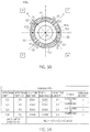
- FIG. 30 is a cross-sectional view on the XY plane illustrating a deformed state when a positive torque around the Z axis acts on a left side supporting body in a state where a load is applied to the right side supporting body in the basic structure illustrated in FIG. 24 .
- FIG. 31 is a table illustrating a behavior of each detection portion when deformation illustrated in FIG. 30 occurs.
- FIG. 32 is a circuit diagram illustrating an example of the detection circuit used in the torque sensor according to a basic embodiment illustrated in FIG. 15 .
- FIG. 33 is a schematic plan view illustrating the basic structural part of the one electrode type torque sensor including a deformation portion of a waveform according to the present invention.
- FIG. 34 is a graph illustrating a relationship between a magnitude of the torque acting on the torque sensor and a first electric signal T 1 a and a second electric signal T 2 a output from the torque sensor in a case (initial state) where metal fatigue does not occur in an annular deformation body of FIG. 33 .
- FIG. 35 is a graph illustrating a relationship between a magnitude of the torque acting on the torque sensor and a first electric signal T 1 b and the second electric signal T 2 b output from the torque sensor in a case where metal fatigue occurs in an annular deformation body of FIG. 33 .
- FIG. 36 is a schematic plan view illustrating the basic structural part of the two electrode type torque sensor according to the present invention which includes a waveform detection portion.
- FIG. 37 is a schematic plan view illustrating the basic structural part of the four electrode type torque sensor according to the present invention which includes the waveform detection portion.
- FIG. 38 is a schematic front view illustrating a modified example of the basic structural part that can be adopted in the torque sensor of the present invention.
- FIG. 39 is a view illustrating arrangement of a fixed electrode and a displacement electrode in a case where a capacitive element is configured between an annular deformation body and an inner supporting body.
- FIG. 40 is a view illustrating a principle for maintaining an effective area of the capacitive element constant even when a relative position of the displacement electrode with respect to the fixed electrode changes.
- FIG. 1 is an exploded perspective view of a basic structural part of the conventional torque sensor. As illustrated, this basic structural part is configured by arranging an annular deformation body 30 between a left side supporting body 10 and a right side supporting body 20 and joining these three constituent elements to each other.
- this basic structural part is configured by arranging an annular deformation body 30 between a left side supporting body 10 and a right side supporting body 20 and joining these three constituent elements to each other.
- the following description will be given defining an XYZ three-dimensional coordinate system, as illustrated, for the sake of convenience.
- a Z axis drawn in the horizontal direction in FIG. 1 corresponds to a rotation axis of a torque, which is an object to be detected, and this torque sensor serves a function to detect the torque around this rotation axis (around the Z axis).
- the annular deformation body 30 arranged at the center of FIG. 1 is made of a material elastically deformable by action of a torque which is an object to be detected, and a through opening H 30 through which a rotation axis (Z axis) passes is formed inside the annular deformation body 30 .
- the left side supporting body 10 arranged on the left side of FIG. 1 is a member that supports a left side face of the annular deformation body 30
- the right side supporting body 20 arranged on the right side of FIG. 1 is a member that supports a right side face of the annular deformation body 30 .
- the left side supporting body 10 is an annular member formed with a through opening H 10 through which the rotation axis (Z axis) passes
- the right side supporting body 20 is an annular member formed with a through opening H 20 through which the rotation axis (Z axis) passes.
- a concept of the right side and the left side is generally a concept that is meaningful only as viewed from a specific observation direction.
- a reference observation direction an observation direction in which a right direction is a positive direction of the Z axis
- Z axis the rotation axis
- a supporting body arranged at a position adjacent to the left side of the annular deformation body 30 is referred to as the left side supporting body 10
- a supporting body arranged at a position adjacent to the right side of the annular deformation body 30 is referred to as the right side supporting body 20 for convenience of description.
- an origin O of the XYZ three-dimensional coordinate system is defined at a center position of the annular deformation body 30 , and all of the left side supporting body 10 , the annular deformation body 30 , and the right side supporting body 20 are configured of the annular members having the Z axis as a central axis thereof.
- the annular deformation body 30 is formed of the annular member obtained by forming the through opening H 30 having a concentric disc shape with a smaller diameter at a central portion of a disc arranged with the Z axis (rotation axis) as a central axis.
- the left side supporting body 10 and the right side supporting body 20 are also formed of the annular members obtained by forming the through openings H 10 and H 20 each of which has a concentric disk shape with a smaller diameter at the central portion of the disc arranged with the Z axis (rotation axis) as the central axis. It is a matter of course that the through openings H 10 and H 20 are not necessarily provided, and the left side supporting body 10 and the right side supporting body 20 may be disks.
- two fan-shaped convex portions 11 and 12 projecting to the right are provided on a right side face of the left side supporting body 10 , and top faces of the convex portions 11 and 12 are joined to the left side face of the annular deformation body 30 .
- the convex portion 11 is joined to an upper portion (portion positioned in a positive Y axis direction) of the annular deformation body 30
- the convex portion 12 is joined to a lower portion (portion positioned in a negative Y axis direction) of the annular deformation body 30 .
- two fan-shaped convex portions 21 and 22 projecting to the left are provided on a left side face of the right side supporting body 20 , and top faces of the convex portions 21 and 22 are joined to the right side face of the annular deformation body 30 .
- the convex portion 21 is joined to a deep portion (portion positioned in a positive X axis direction) of the annular deformation body 30
- the convex portion 22 is joined to a front portion (portion positioned in a negative X axis direction) of the annular deformation body 30 .
- FIG. 2 is a side view of a basic structural part of a torque sensor obtained by joining the three constituent elements illustrated in FIG. 1 to each other
- FIG. 3 is a side sectional view of this basic structural part cut along a YZ plane.
- the convex portions 11 and 12 are structural bodies integrated with the left side supporting body 10 , and the top faces thereof are joined to the left side face of the annular deformation body 30 as illustrated in FIG. 3 .
- the convex portions 21 and 22 are structural bodies integrated with the right side supporting body 20 , and the top faces thereof are joined to the right side face of the annular deformation body 30 .
- the convex portions 11 and 12 function as left side connection members that connect a left side connection point on the left side face of the annular deformation body 30 opposing the left side supporting body 10 to the left side supporting body 10
- the convex portions 21 and 22 function as right side connection members that connect a right side connection point on the right side face of the annular deformation body 30 opposing the right side supporting body 20 to the right side supporting body 20 .
- FIG. 4 is a front view of the left side supporting body 10 and the convex portions 11 and 12 as viewed from the right direction of FIG. 1
- FIG. 5 is a front view of the annular deformation body 30 as viewed from the right direction of FIG. 1
- FIG. 6 is a front view of the right side supporting body 20 and the convex portions 21 and 22 as viewed from the right direction of FIG. 1
- points P 11 and P 12 illustrated at center positions of the convex portions 11 and 12 are the left side connection points, and are used to describe connection positions with respect to the annular deformation body 30 in ⁇ 2.
- points P 21 and P 22 illustrated at center positions of the convex portions 21 and 22 are the right side connection points, and are also used to describe the connection positions with respect to the annular deformation body 30 in ⁇ 2.
- the circular through opening H 30 is provided in the annular deformation body 30 , which is configured to cause elastic deformation that is necessary for detection.
- the annular deformation body 30 needs to be deformed into an elliptical shape when the torque to be detected acts on this basic structural part.
- the easiness of such elastic deformation of the annular deformation body 30 is a parameter which determines a detection sensitivity of the sensor.
- the annular deformation body 30 which is liable to be elastically deformed is used, it is possible to realize a highly sensitive sensor capable of detecting even a minute torque, but a maximum value of a detectable torque is suppressed.
- the annular deformation body 30 which is hardly elastically deformed it is possible to increase the maximum value of the detectable torque, but the sensitivity is lowered so that it is difficult to detect the minute torque.
- the ease of elastic deformation of the annular deformation body 30 is determined depending on the thickness in the Z axis direction (likely to be elastically deformed as the thickness becomes thinner) and the diameter of the through opening H 30 (likely to be elastically deformed as the diameter becomes larger), and further determined depending on its material. Accordingly, a dimension and a material of each part of the annular deformation body 30 may be appropriately selected according to an application of the torque sensor in practical use.
- the left side supporting body 10 and the right side supporting body 20 do not need to be members that cause elastic deformation in terms of the detection principle of the present invention. Rather, it is preferable that the left side supporting body 10 and the right side supporting body 20 be completely rigid bodies in order to make the acting torque contribute 100% to the deformation of the annular deformation body 30 .
- a reason for using the annular structural bodies having the through openings H 10 and H 20 at the central portions thereof as the left side supporting body 10 and the right side supporting body 20 is not for facilitating the elastic deformation, but for securing an insertion hole penetrating the through openings H 10 , H 30 and H 20 of the left side supporting body 10 , the annular deformation body 30 , and the right side supporting body 20 along the rotation axis (Z axis).
- this basic structural part adopts a structure whose interior is hollow.
- the torque sensor having such a hollow portion is used in the state of being incorporated in a joint portion of a robot arm, it is possible to arrange a decelerator or the like in this hollow portion, which allows designing the robot arm that is space saving on the whole.
- This is one of advantages which are hardly realized with the conventional torque sensor that uses torsion of a torsion bar having a solid round bar shape.
- the left side supporting body 10 and the right side supporting body 20 do not need to cause elastic deformation, and rather, are preferably configured of the material with high rigidity in the torque sensor according to the present invention.
- the materials of the left side supporting body 10 , the right side supporting body 20 , and the annular deformation body 30 it is sufficient to use a synthetic resin such as plastic as long as an insulating material is used, and it is sufficient to use metal such as stainless steel and aluminum as long as a conductive material is used (in this case, it is necessary to insulate a necessary part such that an electrode is not short-circuited).
- the insulating material and the conductive material may be used in combination.
- All the left side supporting body 10 , the right side supporting body 20 , and the annular deformation body 30 can be configured of a flat structural body having a small thickness in an axial direction, and thus, it is possible to set an axial length of the entire sensor to be short.
- FIG. 7 is a cross-sectional view of the basic structural part illustrated in FIG. 2 cut along an XY plane and viewed from a left direction of FIG. 2 .
- a XY coordinate system illustrated in FIG. 7 is obtained by viewing a general XY coordinate system from the back side (the positive X axis direction is the left direction in the drawing). Accordingly, an upper left region is the first quadrant, an upper right region is the second quadrant, a lower right region is the third quadrant, and a lower left region is the fourth quadrant in this XY coordinate system.
- I to IV indicate the respective quadrants of this coordinate system.
- the sectional part with hatching in FIG. 7 corresponds to the part of the annular deformation body 30 , and the right side supporting body 20 is visible at the back thereof.
- the points P 11 to P 22 in FIG. 7 are orthogonal projection images of the connection points P 11 to P 22 illustrated in FIGS. 4 and 6 on the XY plane.
- the points P 11 and P 12 arranged on the Y axis indicate joint positions (center points of joint faces) of the convex portions 11 and 12 of the left side supporting body 10
- the points P 21 and P 22 arranged on the X axis indicate joint positions (center points of joint faces) of the convex portions 21 and 22 of the right side supporting body 20
- the left side face of the annular deformation body 30 is joined to the left side supporting body 10 at the two connection points P 11 and P 12 along the Y axis
- the right side face of the annular deformation body 30 is joined to the right side supporting body 20 at the two connection points P 21 and P 22 along the X axis.
- the annular deformation body 30 can be efficiently deformed by action of the torque.
- a projection image of the first right side connection point P 21 is arranged on the positive X axis
- a projection image of the second right side connection point P 22 is arranged on the negative X axis
- a projection image of the first left side connection point P 11 is arranged on the positive Y axis
- a projection image of the second left side connection point P 12 is arranged on the negative Y axis.
- the annular deformation body 30 can be deformed into an axially symmetric ellipse by performing such arrangement, and thus, it is possible to obtain a detection value having axial symmetry.
- the torque sensor according to the present invention is configured to detect the torque (rotational moment) relatively applied between the left side supporting body 10 and the right side supporting body 20 , and the detection value indicates a force that relatively acts between the supporting bodies 10 and 20 .
- the torque rotational moment
- the left side supporting body 10 in a state where a load is applied to the right side supporting body 20 is considered as the torque to be detected (as a matter of course, it is equivalent even if a rotational moment applied to the right side supporting body 20 in a state where a load is applied to the left side supporting body 10 is considered as the torque to be detected) for convenience of description.
- a drive source such as a motor
- a robot hand is attached to the right side supporting body 20 as an example of using such a torque sensor in the joint portion of the robot arm.
- a rotational driving force is applied to the left side supporting body 10 from the drive source in a state where a heavy object is gripped by the robot hand
- this rotational drive force is transmitted to the robot hand side via the basic structural part forming the joint portion.
- a torque to rotationally drive the right side supporting body 20 acts, and this torque corresponds to the rotational moment applied to the left side supporting body 10 in a state where the right side supporting body 20 is fixed.
- connection points P 21 and P 22 on the X axis illustrated in FIG. 7 are in a fixed state.
- connection points P 11 and P 12 on the Y axis move clockwise.
- FIG. 8 is a cross-sectional view illustrating a state where such deformation occurs in the structural body illustrated in FIG. 7 . That is, FIG. 8 is the cross-sectional view of the basic structural part cut along the XY plane and viewed from the left direction in FIG. 2 when a positive torque in the Z axis acts on the basic structural part illustrated in FIG. 2 .
- a rotation direction for advancing a right screw in a positive direction of the coordinate axis is defined as the positive direction
- a rotation direction for advancing the right screw in a negative direction of the coordinate axis is defined as the negative direction in the present application.
- the positive torque around the Z axis is the torque acting in the clockwise direction as indicated by the hollow arrow in FIG. 8 .
- the dashed line drawn in FIG. 8 indicates a state of the annular deformation body 30 before deformation (the state of FIG. 7 ). Referring to this broken line, it is possible to easily grasp that the annular deformation body 30 is deformed into an elliptical shape due to the action of the positive torque around the Z axis.
- a V axis and a W axis which pass through the origin O and form 45° with respect to the X axis and the Y axis, respectively, are defined on the XY plane for convenience of description.
- the V axis is a coordinate axis with the first quadrant I as the positive direction and the W axis is a coordinate axis with the second quadrant II as the positive direction.
- the annular deformation body 30 is deformed into the ellipse with the V axis as a short-axis direction and the W axis as a long-axis direction, and has axial symmetry with respect to the V axis and the W axis.
- Such axial symmetry is convenient in the case of obtaining a torque detection value using a method to be described in ⁇ 3.
- the deformation with axial symmetry occurs because the annular deformation body 30 is a perfect circle when there is no load (when no torque acts), and the projection image of the first right side connection point P 21 is arranged on the positive X axis, the projection image of the second right side connection point P 22 is arranged on the negative X axis, the projection image of the first left side connection point P 11 is arranged on the positive Y axis, and the projection image of the second left side connection point P 12 is arranged on the negative Y axis in the case of obtaining the orthogonal projection images by projecting both the side faces of the annular deformation body 30 on the XY plane, as illustrated in FIG. 7 .
- the annular deformation body 30 is deformed into a more flattened ellipse as the acting torque becomes greater. Accordingly, it is possible to obtain the magnitude of the acting torque if it is possible to measure a distance of a portion of the annular deformation body 30 positioned on the V axis from the origin O, or a distance of a portion of the annular deformation body 30 positioned on the W axis from the origin O (these distances serve as information indicating a displacement amount from a position before deformation indicated by the broken line) in FIG. 8 . In other words, it is enough if displacement in the radial direction of the inner peripheral face or the outer peripheral face of the annular deformation body 30 is measured.
- a rotational force in a counterclockwise direction acts with respect to (the connection points P 11 and P 12 of) the annular deformation body 30 so that the annular deformation body 30 deforms into an ellipse with the V axis as the long-axis direction and the W axis as the short-axis direction, which is opposite to the example illustrated in FIG. 8 .
- a displacement direction of a portion positioned on the V axis or a portion positioned on the W axis of the annular deformation body 30 is opposite to the direction of the example illustrated in FIG. 8 .
- the displacement of the annular deformation body 30 in the radial direction occurring in the torque sensor according to the present invention is relatively great depending on a diameter of the annular deformation body even if a torsion angle generated in the annular deformation body 30 is small.
- the torque detection principle according to the present invention has been described as above.
- a capacitive element and a detection circuit are further added to the basic structural part described above in order to perform torque detection based on such a principle.
- the torque sensor is configured by further adding the capacitive element and the detection circuit to the basic structural part illustrated in FIG. 3 .
- the annular deformation body 30 is deformed into the ellipse by action of the torque. Since a portion causing the largest displacement through such displacement is the portion positioned on the V axis or the portion positioned on the W axis, to measure the displacement of the portion positioned on the V axis or the portion positioned on the W axis is the most efficient in measurement of the displacement amount (magnitude of the acting torque) of the annular deformation body 30 based on the displacement of a specific portion of the annular deformation body 30 .
- FIG. 9 is a plan view of the annular deformation body 30 in a state where displacement electrodes E 31 and E 32 are formed on the inner circumferential surface thereof as viewed from the left direction of FIG. 2 .
- the X, Y, V and W axes are drawn in an overlapping manner.
- the displacement electrode E 31 is an electrode formed in an intersection region between a positive region of the V axis and the inner peripheral face of the annular deformation body 30
- the displacement electrode E 32 is an electrode formed in an intersection region between a positive region of the W axis and the inner peripheral face of the annular deformation body 30
- a depth dimension (dimension in a direction perpendicular to the sheet plane of FIG. 9 ) of these displacement electrodes E 31 is equal to a depth dimension of the annular deformation body 30
- the displacement electrodes E 31 and E 32 are configured of a conductive layer such as a metal film formed by vapor deposition, plating, or the like on the inner peripheral face of the annular deformation body 30 . It is a matter of course that it is necessary to form the displacement electrodes E 31 and E 32 via an insulating layer since the annular deformation body 30 itself has conductivity when the annular deformation body 30 is made of metal such as aluminum and stainless steel.
- FIG. 10 is a plan view of the right side supporting body 20 in a state where the fixed electrodes E 21 and E 22 are attached thereto as viewed from the left direction of FIG. 2 .
- the X, Y, V and W axes are also drawn in an overlapping manner for convenience of description.
- the fixed electrode E 21 is arranged in the positive region of the V axis and opposes the displacement electrode E 31 .
- the fixed electrode E 22 is arranged in the positive region of the W axis and opposes the displacement electrode E 32 .
- FIG. 11 is a side view of the right side supporting body 20 illustrated in FIG. 10 .
- the fixed electrode E 21 is configured of a conductive plate that projects from the left side face of the right side supporting body 20 in the direction along the rotation axis (the negative Z axis direction).
- the fixed electrode E 21 is hidden behind the fixed electrode E 22 , and does not appear in FIG. 11 .
- FIG. 12 is a side cross-sectional view of the structural body in which the displacement electrode and the fixed electrode are added to the basic structural part illustrated in FIG. 3 that is cut along a VZ plane. Since FIG. 12 is the side sectional view cut along the VZ plane while FIG. 3 is the side sectional view cut along the YZ plane, the upper side of FIG. 12 is not the Y axis direction but the V axis direction illustrated in FIGS. 9 and 10 . A state where the displacement electrode E 31 and the fixed electrode E 21 arranged on the V axis oppose each other is clearly illustrated in the side sectional view of FIG. 12 .
- the displacement electrodes E 31 and E 32 are electrodes fixed to the inner peripheral face of the annular deformation body 30 , and thus, are displaced depending on the deformation of the annular deformation body 30 .
- right ends of the fixed electrodes E 21 and E 22 are fixed to the right side supporting body 20 so that the fixed electrodes E 21 and E 22 always maintain each constant position regardless of the deformation of the annular deformation body 30 .
- a relative position of the displacement electrode E 31 with respect to the fixed electrode E 21 and a relative position of the displacement electrode E 32 with respect to the fixed electrode E 22 change depending on the deformation of the annular deformation body 30 .
- an inter-electrode distance between the displacement electrode E 31 and the fixed electrode E 21 and an inter-electrode distance between the displacement electrode E 32 and the fixed electrode E 22 change depending on the deformation of the annular deformation body 30 .
- FIG. 13 is a cross-sectional view of the structural body in which the displacement electrode and the fixed electrode described above are added to the basic structural part illustrated in FIG. 2 that is cut along the XY plane and viewed from the left direction of FIG. 2 .
- a state where the displacement electrodes E 31 and E 32 and the fixed electrodes E 21 and E 22 arranged on the V axis oppose each other is clearly illustrated in this side sectional view.
- the displacement electrodes E 31 and E 32 are configured of the conductive layers formed on the inner peripheral face of the annular deformation body 30 in the present embodiment, surfaces thereof become curved surfaces along an inner periphery of the annular deformation body 30 .
- the fixed electrodes E 21 and E 22 opposing the displacement electrodes E 31 and E 32 are also formed as curved electrodes.
- the surfaces of the displacement electrodes E 31 and E 32 and the fixed electrodes E 21 , E 22 are configured by concentric cylindrical surfaces with the Z axis as a central axis thereof.
- the surface shape of each electrode may be any shape as long as it is possible to serve the role of forming the capacitive element, and thus, a planar electrode whose surface is planar may be used.
- each displacement electrode and each fixed electrode is drawn ignoring an actual dimension thereof in the drawings of the present application for convenience of illustration.
- the displacement electrodes E 31 and E 32 are configured of a conductive layer (a vapor-deposited layer or a plating layer) formed on the inner peripheral face of the annular deformation body 30 , the thickness thereof can be set to about several ⁇ m.
- the fixed electrodes E 21 and E 22 are configured of a conductive plate (metal plate) projecting from the left side surface of the right side supporting body 20 , it is preferable to secure the thickness thereof to be about several mm in order to secure strength in practical use.
- the thickness of the displacement electrode and the thickness of the fixed electrode are drawn to have the same dimension in FIG. 13 and the like for the sake of convenience, but the actual thickness dimensions of these electrodes need to be respectively set to appropriate values in consideration of a manufacturing process and the strength in practical use.
- FIG. 14 is an XY cross-sectional view illustrating a state where the positive torque around the Z axis acts on the basic structural part illustrated in FIG. 13 .
- the annular deformation body 30 deforms into the elliptical shape, the V axis becomes the short-axis direction of the ellipse, and the W axis becomes the long-axis direction of the ellipse.
- an inter-electrode interval between the pair of electrodes E 21 and E 31 arranged on the V axis is narrowed, and an inter-electrode interval between the pair of electrodes E 23 and E 33 arranged on the W axis is widened.
- the inter-electrode interval is narrowed when the positive torque around the Z axis acts as illustrated in FIG. 14 , and thus, the capacitance value increases. Conversely, the inter-electrode interval is widened when the negative torque around the Z axis acts, and thus, the capacitance value decreases. Accordingly, an incremental variation of the capacitance value indicates the action of the positive torque around the Z axis, and a decremental variation of the capacitance value indicates the action of the negative torque around the Z axis. It is a matter of course that an absolute value of the variation amount indicates the magnitude of the acting torque.
- the inter-electrode interval is widened when the positive torque around the Z axis acts as illustrated in FIG. 14 , and thus, the capacitance value decreases. Conversely, the inter-electrode interval is narrowed when the negative torque around the Z axis acts, and thus, the capacitance value increases. Accordingly, a decremental variation of the capacitance value indicates the action of the positive torque around the Z axis, and an incremental variation of the capacitance value indicates the action of the negative torque around the Z axis. It is a matter of course that an absolute value of the variation amount indicates the magnitude of the acting torque.
- the inter-electrode interval is widened and the capacitance value decreases at the long-axis position (on the W axis) while the inter-electrode interval is narrowed and the capacitance value increases at the short-axis position (on the V axis) in the case of applying the same torque.
- the acting torque it is possible to detect the acting torque as a difference between the two capacitance values C 11 and C 12 .
- FIG. 15 is an XY-sectional view illustrating a basic structural part of the two electrode type torque sensor according to the present invention.
- the annular deformation body 30 according to the present embodiment includes a high elastic portion 30 a and a low elastic portion 30 b having a spring constant smaller than a spring constant of the high elastic portion 30 a .
- a semicircular ring portion of the annular deformation body 30 arranged in a region where a Y coordinate is positive is configured as the high elastic portion 30 a
- the remaining semicircular ring portion arranged in a region where a Y coordinate is negative is configured as the low elastic portion 30 b .
- the spring constant of the high elastic portion 30 a is set to be larger than the spring constant of the low elastic portion 30 b by making a thickness of the high elastic portion 30 a in the radial direction to be larger than a thickness of the low elastic portion 30 b in the radial direction herein, as illustrated in the drawing.
- the spring constant of the high elastic portion 30 a it is also possible to set the spring constant of the high elastic portion 30 a to be larger than the spring constant of the low elastic portion 30 b by making a thickness of the high elastic portion 30 a in the Z axis direction to be larger than a thickness of the low elastic portion 30 b in the Z axis direction, and it is also possible to set the spring constant of the high elastic portion 30 a to be larger than the spring constant of the low elastic portion 30 b by configuring the high elastic portion 30 a and the low elastic portion 30 b using different materials.
- the high elastic portion 30 a and the low elastic portion 30 b are connected such that no step is formed on an inner peripheral face thereof, and the inner peripheral face of the annular deformation body 30 has a circular shape as viewed from the Z axis direction in the example illustrated in FIG. 15 .
- all distances from the origin O to four portions where the inner peripheral face of the annular deformation body 30 meets the V axis and the W axis are set to be equal.
- displacement electrodes E 31 a , E 32 a , E 31 b and E 32 b are arranged at positions corresponding to these four portions, respectively, as illustrated in the drawing.
- the displacement electrode E 31 a is an electrode formed in a region where the positive region of the V axis meets an inner peripheral face of the high elastic portion 30 a of the annular deformation body 30
- the displacement electrode E 32 a is an electrode formed in a region where the positive region of the W axis meets the inner peripheral face of the high elastic portion 30 a of the annular deformation body 30 .
- the displacement electrode E 31 b is an electrode formed in a region where the negative region of the V axis meets an inner peripheral face of the low elastic portion 30 b of the annular deformation body 30
- the displacement electrode E 32 b is an electrode formed in a region where the negative region of the W axis meets the inner peripheral face of the low elastic portion 30 b of the annular deformation body 30 .
- fixed electrodes E 21 a , E 22 a , E 21 b and E 22 b are arranged at positions opposite to the displacement electrodes E 31 a , E 32 a , E 31 b and E 32 b , respectively, and are fixed to the right side supporting body 20 . Since the configurations of the right side supporting body 20 and the left side supporting body 10 are the same as those of the conventional torque sensor described above, the detailed description thereof will be omitted.
- the torque sensor in which two capacitive elements are arranged to each of the high elastic portion 30 a and the low elastic portion 30 b is referred to as the two electrode type torque sensor.
- FIG. 16 is an XY cross-sectional view illustrating a deformed state of the basic structural part of FIG. 15 when a positive torque around the Z axis acts on the torque sensor according to the present embodiment.
- the annular deformation body 30 deforms into an elliptical shape, the V axis becomes the short-axis direction of the ellipse, and the W axis becomes the long-axis direction of the ellipse.
- the spring constant of the high elastic portion 30 a is larger than the spring constant of the low elastic portion 30 b in the annular deformation body 30 according to the present embodiment.
- a degree of deformation of the low elastic portion 30 b is larger than a degree of deformation of the high elastic portion 30 a as illustrated in the drawing.
- both inter-electrode intervals between the pair of electrodes E 21 a and E 31 a and between the pair of electrodes E 21 b and E 31 b arranged on the V axis are narrowed, but a narrowing degree thereof is larger in the inter-electrode interval between the pair of electrodes E 21 b and E 31 b arranged on the negative V axis.
- both inter-electrode intervals between the pair of electrodes E 22 a and E 32 a and between the pair of electrodes E 22 b and E 32 b arranged on the W axis are widened, but a widening degree thereof is larger in the inter-electrode interval between the pair of electrodes E 22 b and E 32 b arranged on the negative W axis.
- each displacement direction of the displacement electrodes E 31 a , E 31 b , E 32 a and E 32 b positioned on the V axis and the W axis of the annular deformation body 30 is opposite to that in the example illustrated in FIG. 16 .
- a first electric signal T 1 which corresponds to a difference between a capacitance value of a capacitive element C 1 a configured of the pair of electrodes E 21 a and E 31 a and a capacitance value of a capacitive element C 2 a configured of the pair of electrodes E 22 a and E 32 a , as shown in the following [Expression 1].
- a second electric signal T 2 which corresponds to a difference between a capacitance value of a capacitive element C 1 b configured of the pair of electrodes E 21 b and E 31 b and a capacitance value of a capacitive element C 2 b configured of the pair of electrodes E 22 b and E 32 b .
- C 1 a and C 2 a , C 1 b and C 2 b indicate capacitance values of the capacitive elements C 1 a and C 2 a , C 1 b and C 2 b , respectively, in the following [Expression 1].
- T 1 C 1 a ⁇ C 2 a
- T 2 C 1 b ⁇ C 2 b [Expression 1]
- the malfunction diagnosis of the torque sensor is performed by utilizing a fact that a ratio between the first and second electric signals T 1 and T 2 changes along with accumulation of metal fatigue in the annular deformation body 30 .
- first and second electric signals in an initial state where the metal fatigue does not occur in the annular deformation body 30 are denoted by T 1 a and T 2 a
- first and second electric signals in a state where the metal fatigue occurs (is accumulated) in the annular deformation body 30 are denoted by T 1 b and T 2 b to distinguish from each other in the following description.
- FIG. 17 is a graph illustrating a relationship between the magnitude of the torque acting on the torque sensor and the first electric signal T 1 a and the second electric signal T 2 a output from the torque sensor in the state (initial state) where the metal fatigue does not occur in the annular deformation body 30 of FIG. 15 .
- FIG. 18 is a graph illustrating a relationship between the magnitude of the torque acting on the torque sensor and the first electric signal T 1 b and the second electric signal T 2 b output from the torque sensor in a state where the metal fatigue occurs (is accumulated) in the annular deformation body 30 of FIG. 15 .
- the horizontal axis represents a torque acting on the torque sensor and the vertical axis represents a magnitude of an electric signal output from the torque sensor according to the torque.
- an inclination of a straight line indicating each of the electric signals T 1 a to T 2 b represents a detection sensitivity of the torque sensor in each drawing.
- the basic structural part according to the present embodiment is equivalent to a configuration in which the two basic structural parts of the conventional two electrode type described above are arranged with different sensitivities.
- the inclination of each straight line depends on the spring constants of the corresponding high elastic portion 30 a and low elastic portion 301 .
- the metal fatigue occurs in the annular deformation body 30 .
- the metal fatigue is remarkably developed in the low elastic portion 30 b in which the deformation caused by the torque is relatively large.
- strength of the low elastic portion 30 b decreases, and finally, the annular deformation body 30 breaks.
- the metal material is softened so that the spring constant of the low elastic portion 30 b decreases.
- the low elastic portion 30 b is largely deformed by the torque, and the sensitivity of the low elastic portion 30 b with respect to the torque increases as compared with the initial state. This fact can be understood by comparing FIG. 17 and FIG. 18 .
- an inclination (sensitivity) of the straight line indicating the second electric signal T 2 a corresponding to the low elastic portion 30 b is 2.0 in the initial state when referring to FIG. 17 .
- an inclination (sensitivity) of the straight line indicating the second electric signal T 2 b corresponding to the low elastic portion 30 b is 3.0 in the state where the metal fatigue is accumulated, and the sensitivity increases by 50% when referring to FIG. 18 .
- an inclination (sensitivity) of the straight line indicating the first electric signal T 1 a corresponding to the high elastic portion 30 a is 0.5 in the initial state when referring to FIG. 17 .
- an inclination (sensitivity) of the straight line indicating the first electric signal T 1 b corresponding to the high elastic portion 30 a in the state where the metal fatigue is accumulated is 0.6 when referring to FIG. 18 . Accordingly, an increase of the sensitivity is only 20%.
- the degree of the development of metal fatigue differs between the high elastic portion 30 a and the low elastic portion 30 b . That is, a ratio (T 2 a /T 1 a ) between the first electric signal T 1 a and the second electric signal T 2 a is 4.0 in the initial state, whereas a ratio (T 2 b /T 1 b ) between the first electric signal T 1 b and the second electric signal T 2 b increases to 5.0 in the state where the metal fatigue is accumulated.
- the present invention utilizes this fact to perform the malfunction diagnosis of the torque sensor.
- the ratio between the first electric signal T 1 and the second electric signal T 2 gradually changes due to the difference in characteristic of accumulation of metal fatigue between the high elastic portion 30 a and the low elastic portion 30 b .
- the annular deformation body 30 finally is broken in the low elastic portion 30 b , and it is difficult for the two capacitive elements C 1 b and C 2 b arranged on the low elastic portion 30 b side to function normally.
- the torque sensor according to the present embodiment includes a detection circuit illustrated in FIG. 19 .
- FIG. 19 is a block diagram of the detection circuit adopted in the torque sensor according to the present embodiment.
- This detection circuit includes a C/V converter 41 which converts information on capacitance values of the four capacitive elements provided from the mechanism including the annular deformation body 30 and the capacitive elements C 1 a and C 2 a , C 1 b and C 2 b into the respective corresponding voltage values, a microcomputer 47 which performs each difference processing of the four voltage values provided from the C/V converter 41 corresponding to [Expression 1], and calculates the torque acting on the torque sensor by calculating the first electric signal T 1 and the second electric signal T 2 described above, and a storage unit 48 which is connected to the microcomputer 47 and stores the ratio in the initial state between the first electric signal T 1 a and the second electric signal T 2 a .
- the microcomputer 47 has a function of comparing the initial state ratio stored in the storage unit 48 and a current ratio
- the microcomputer 47 determines that the torque sensor functions normally and outputs a value of the measured torque.
- the torque is measured using the first electric signals T 1 a and T 1 b provided based on the capacitive elements C 1 a and C 2 a provided on the high elastic portion 30 side. This is because it is considered that the influence of metal fatigue is small and it is possible to measure the torque with higher accuracy since the metal elastic fatigue is less likely to occur in the high elastic portion 30 a than in the low elastic portion 30 b as described above.
- the microcomputer 47 determines that the torque sensor does not function normally (malfunctions) and outputs a malfunction diagnosis signal.
- the torque measurement may be performed based on the variation amount of the capacitance values of the capacitive elements C 1 b and C 2 b arranged to the low elastic portion 30 b .
- These capacitive elements C 1 b and C 2 b greatly change (have the high sensitivities) with respect to the torque compared with the capacitive elements C 1 a and C 2 a , and thus, it is possible to perform the torque measurement with an excellent S/N.
- the fixed electrodes E 21 a , E 22 a , E 21 b and E 22 b are fixed to the right side supporting body 20 in the present embodiment, but the fixed electrodes may be fixed to the left side supporting body 10 .
- the fixed electrode E 21 is configured of the conductive plate projecting to the left from the left side face of the right side supporting body 20 in the example illustrated in FIG. 12
- the fixed electrode E 21 may be configured of a conductive plate projecting to the right from the right side face of the left side supporting body 10 .
- the fixed electrode E 21 may be provided at a fixed position opposing the displacement electrode E 31 so as to be maintained regardless of the deformation of the annular deformation body 30 .
- the displacement electrodes E 31 a , E 32 a , E 31 b and E 32 b are fixed to the inner peripheral face of the annular deformation body 30 in the embodiment illustrated herein, but the displacement electrodes may be fixed to the outer peripheral face of the annular deformation body 30 .
- the displacement electrode may be formed on the outer peripheral face of the annular deformation body 30 .
- the fixed electrode opposing the displacement electrode may be arranged on a further outer side of the displacement electrode.
- the respective electrodes with high symmetry if the high elastic portion 30 a and the low elastic portion 30 b are smoothly connected to each other so as not to generate a step on the outer peripheral face thereof.
- the low elastic portion 30 b is configured to have the thickness in the radial direction of the annular deformation body 30 smaller than the thickness of the high elastic portion 30 a in the radial direction, a step is generated at a connection portion between the high elastic portion 30 a and the low elastic portion 30 b on the inner peripheral face of the annular deformation body 30 .
- the overall size of the sensor increases when adopting a structure in which each electrode is arranged on the outer side of the annular deformation body 30 , and thus, it is preferable to provide the displacement electrode on the inner peripheral face of the annular deformation body 30 as in the above-described embodiment, in practical use.
- the size is the same even if the displacement electrode is arranged at the outer side in modified examples illustrated in FIGS. 38 and 39 to be described later.
- the ratio between the first electric signal T 1 and the second electric signal T 2 changes as the low elastic portion 30 b undergoes the metal fatigue earlier than the high elastic portion 30 a .
- the torque sensor in which the two capacitive elements are arranged to each of the high elastic portion 30 a and the low elastic portion 30 b has been described as the two electrode type torque sensor. Since this torque sensor can perform the difference detection using the respective two capacitive elements, it is possible to perform the torque measurement with high accuracy while excluding influence of a change in temperature. However, when the temperature is constant or when temperature compensation is performed, it is possible to perform torque detection and malfunction diagnosis using a single torque sensor even if only one capacitive element is arranged to each of the high elastic portion 30 a and the low elastic portion 30 b .
- the torque sensor in which one capacitive element is arranged to each of the high elastic portion 30 a and the low elastic portion 30 b is referred to as a one electrode type torque sensor.
- FIG. 20 is an XY-sectional view illustrating a basic structural part of the one electrode type torque sensor according to the present invention.
- the X, Y, V and W axes are also drawn in an overlapping manner for convenience of description.
- the annular deformation body 30 of the torque sensor according to the present embodiment has the same structure as the annular deformation body 30 of the two electrode type torque sensor described in ⁇ 4.
- the displacement electrode E 31 a is arranged in the intersection region between the positive region of the V axis and the inner peripheral face of the high elastic portion 30 a of the annular deformation body 30
- the displacement electrode E 31 b is arranged in the intersection region between the negative region of the V axis and the inner peripheral face of the low elastic portion 30 b of the annular deformation body 30 .
- the fixed electrodes E 21 a and E 21 b are arranged at positions opposite to the displacement electrodes E 31 a and E 31 b , respectively, and are fixed to the right side supporting body 20 .
- the capacitive element C 1 a is configured of the displacement electrode E 31 a and the fixed electrode E 21 a
- the capacitive element C 1 b is configured of the displacement electrode E 31 b and the fixed electrode E 21 b .
- the torque sensor according to the present embodiment has a configuration in which the respective electrodes forming the two capacitive elements C 2 a and C 2 b arranged on the W axis are removed from the two electrode type torque sensor described in ⁇ 4.
- the other configurations are the same as those of the two electrode type torque sensor described in ⁇ 4, and thus, a detailed description thereof will be omitted.
- FIG. 21 is an XY cross-sectional view illustrating a state where a positive torque around the Z axis acts on a basic structural part in FIG. 20 (the broken line indicates a state before deformation).
- the annular deformation body 30 is deformed into an elliptical shape, the V axis becomes a short-axis direction of the ellipse, and the W axis becomes a long-axis direction of the ellipse as described above.
- a spring constant of the high elastic portion 30 a is larger than a spring constant of the low elastic portion 30 b in the annular deformation body 30 .
- a degree of deformation of the low elastic portion 30 b is larger than a degree of deformation of the high elastic portion 30 a as described in ⁇ 4.
- a rotational force in a counterclockwise direction acts with respect to (the connection points P 11 and P 12 of) the annular deformation body 30 when a torque acts in the opposite direction, that is, when a negative torque around the Z axis acts so that the annular deformation body 30 deforms into an ellipse with the V axis as the long-axis direction and the W axis as the short-axis direction, which is opposite to the example illustrated in FIG. 21 .
- a displacement direction of a portion positioned on the V axis of the annular deformation body 30 is opposite to the direction of the example illustrated in FIG. 21 .
- a relationship between the magnitude of the torque acting on the torque sensor and the first and second electric signals T 1 a and T 2 a in the initial state is the same as that of the graph illustrated in FIG. 17 .
- a relationship between the magnitude of the torque acting on the torque sensor and the first and second electric signals T 1 b and T 2 b in a state where metal fatigue occurs in the annular deformation body 30 is the same as that of the graph illustrated in FIG. 18 .
- a principle and a method for determination on whether the torque sensor according to the present embodiment described above functions normally are the same as those in ⁇ 4. That is, it is possible to understand the principle and the method of the malfunction determination of the torque sensor according to the present embodiment by replacing [Expression 2] with the first electric signal T 1 (T 1 a , T 1 b ) and the second electric signal T 2 (T 2 a , T 2 b ) in ⁇ 4. Thus, a detailed description of the principle and method will be omitted herein. However, it is unnecessary for the microcomputer 47 of the detection circuit to perform the difference detection in the present embodiment. Thus, the microcomputer 47 may output two voltage values provided from the C/V converter 41 directly as the first electric signal T 1 and the second electric signal T 2 .
- the ratio between the first electric signal T 1 and the second electric signal T 2 changes as the low elastic portion 30 b undergoes the metal fatigue earlier than the high elastic portion 30 a
- the torque sensor capable of diagnosing the malfunction of the annular deformation body 30 .
- each of the capacitive elements C 1 a and C 1 b is arranged on each of the positive V axis and the negative V axis, and no capacitive element is arranged on the W axis in the above description.
- FIG. 22 is an XY-sectional view illustrating a basic structural part of the four electrode type torque sensor according to the present invention.
- the X, Y, V and W axes are also drawn in an overlapping manner for convenience of description.
- the basic structural part according to the present embodiment is configured such that four high elastic portions 30 a and four low elastic portions 30 b are alternately arranged in a circumferential direction, which is different from the basic structural parts of the two electrode type and one electrode type torque sensors.
- the high elastic portions 30 a are arranged in a region (i) partitioned by a positive X axis and a positive V axis, a region (iii) partitioned by a positive Y axis and a positive W axis, a region (v) partitioned by a negative X axis and a negative V axis, and a region (vii) partitioned by a negative Y axis and a negative W axis, respectively, as viewed from the Z axis direction.
- the low elastic portions 30 b are arranged in remaining regions, that is, a region (ii) partitioned by the positive V axis and the positive Y axis, a region (iv) defined by the positive W axis and the negative X axis, a region (vi) partitioned by the negative V axis and the negative Y axis, and a region (viii) partitioned by the negative W axis and the positive X axis, respectively.
- the four electrode type torque sensor means a torque sensor in which four capacitive elements are arranged to each of the high elastic portion 30 a and low elastic portion 30 b in this manner.
- each of the high elastic portions 30 a and each of the low elastic portions 30 b are connected to each other so as not to generate a step on the inner peripheral face of the annular deformation body 30 .
- eight displacement electrodes E 31 a to E 34 b are arranged on the inner peripheral face.
- the displacement electrode E 31 a is arranged on an inner peripheral face of the high elastic portion 30 a arranged in the region (i) in the vicinity of the positive V axis
- the displacement electrode E 31 b is arranged on an inner peripheral face of the low elastic portion 30 b arranged in the region (ii) in the vicinity of the positive V axis.
- the displacement electrode E 32 a is arranged on an inner peripheral face of the high elastic portion 30 a arranged in the region (iii) in the vicinity of the positive W axis, and the displacement electrode E 32 b is arranged on an inner peripheral face of the low elastic portion 30 b arranged in the region (iv) in the vicinity of the positive W axis.
- the displacement electrode E 33 a is arranged on an inner peripheral face of the high elastic portion 30 a arranged in the region (v) in the vicinity of the negative V axis, and the displacement electrode E 33 b is arranged on an inner peripheral face of the low elastic portion 30 b arranged in the region (vi) in the vicinity of the negative W axis.
- the displacement electrode E 34 a is arranged on an inner peripheral face of the high elastic portion 30 a arranged in the region (vii) in the vicinity of the negative W axis
- the displacement electrode E 34 b is arranged on an inner peripheral face of the low elastic portion 30 b arranged in the region (viii) in the vicinity of the negative W axis.
- fixed electrodes E 21 a to E 24 b are arranged at positions opposing these displacement electrodes E 31 a to E 34 b , respectively, as illustrated in the drawing, and are fixed to a right side supporting body (not illustrated). Further, eight capacitive elements C 1 a to C 4 b are configured of eight sets of these electrodes opposing each other.
- the capacitive element C 1 a configured of the fixed electrode E 21 a and the displacement electrode E 31 a and the capacitive element C 1 b configured of the fixed electrode E 21 b and the displacement electrode E 31 b are arranged to be symmetric with respect to the V axis as viewed from the Z axis direction.
- the capacitive element C 2 a configured of the fixed electrode E 22 a and the displacement electrode E 32 a and the capacitive element C 2 b configured of the fixed electrode E 22 b and the displacement electrode E 32 b are arranged to be symmetric with respect to the W axis as viewed from the Z axis direction.
- the capacitive element C 3 a configured of the fixed electrode E 23 a and the displacement electrode E 33 a and the capacitive element C 3 b configured of the fixed electrode E 23 b and the displacement electrode E 33 b are arranged to be symmetric with respect to the V axis as viewed from the Z axis direction.
- the capacitive element C 4 a configured of the fixed electrode E 24 a and the displacement electrode E 34 a and the capacitive element C 4 b configured of the fixed electrode E 24 b and the displacement electrode E 34 b are arranged to be symmetric with respect to the W axis as viewed from the Z axis direction.
- the other configurations are the same as those of the above-described two electrode type and one electrode type torque sensors, and thus, a detailed description thereof will be omitted.
- FIG. 23 is an XY cross-sectional view illustrating a state where the positive torque around the Z axis acts on the basic structural part illustrated in FIG. 22 .
- the annular deformation body 30 deforms into substantially an elliptical shape, the V axis becomes the short-axis direction of the ellipse, and the W axis becomes the long-axis direction of the ellipse.
- the annular deformation body 30 according to the present embodiment is configured by alternately arranging the high elastic portion 30 a that is less likely to deform and the low elastic portion 30 b that is more likely to deform.
- the degree of displacement of the annular deformation body 30 differs between the high elastic portion 30 a and the low elastic portion 30 b as illustrated in the drawing. Specifically, both the high elastic portion 30 a in the region (i) and the low elastic portion 30 b in the region (ii) are displaced in the positive V axis direction, but the low elastic portion 30 b in the region (ii) is more greatly displaced. Similarly, both the high elastic portion 30 a in the region (iii) and the low elastic portion 30 b in the region (iv) are displaced in the negative W axis direction, but the low elastic portion 30 b in the region (iv) is more greatly displaced.
- both the high elastic portion 30 a in the region (v) and the low elastic portion 30 b in the region (vi) are displaced in the negative V axis direction, but the low elastic portion 30 b in the region (vi) is more greatly displaced.
- Both the high elastic portion 30 a in the region (vii) and the low elastic portion 30 b in the region (viii) are displaced in the positive W axis direction, but the low elastic portion 30 b in the region (viii) is more greatly displaced.
- each displacement of the displacement electrodes E 31 a to E 34 b positioned in the vicinity of the V axis and the W axis of the annular deformation body 30 occurs in a direction opposite to that in the example illustrated in FIG. 23 .
- the torque sensor of the present embodiment it is possible to detect a direction and a magnitude of the acting torque using the first electric signal T 1 based on the respective capacitance values of the capacitive elements C 1 a , C 2 a , C 3 a and C 4 a each of which is configured of the pair of electrodes as shown in the following [Expression 3]. Further, it is also possible to detect the direction and the magnitude of the acting torque using the second electric signal T 2 based on the respective capacitance values of the capacitive elements C 1 b , C 2 b , C 3 b and C 4 b each of which is configured of the pair of electrodes.
- C 1 a to C 4 b indicate the capacitance values of the capacitive elements C 1 a to C 4 b , respectively, in the following [Expression 3].
- T 1 ( C 1 a+C 3 a ) ⁇ ( C 2 a+C 4 a )
- T 2 ( C 1 b+C 3 b ) ⁇ ( C 2 b+C 4 b ) [Expression 3]
- a relationship between the magnitude of the torque acting on the torque sensor and the first and second electric signals T 1 a and T 2 a in the initial state is the same as that of the graph illustrated in FIG. 17 .
- a relationship between the magnitude of the torque acting on the torque sensor and the first and second electric signals T 1 b and T 2 b in a state where metal fatigue occurs in the annular deformation body 30 is the same as that of the graph illustrated in FIG. 18 .
- a principle and a method for determination on whether the torque sensor according to the present embodiment described above functions normally are the same as those in ⁇ 4. That is, it is possible to understand the principle and the method of the malfunction determination of the torque sensor according to the present embodiment by replacing [Expression 3] with the first electric signal T 1 (T 1 a , T 1 b ) and the second electric signal T 2 (T 2 a , T 2 b ) in ⁇ 4. Thus, a detailed description of the principle and method will be omitted herein.
- the microcomputer 47 of the detection circuit outputs the first electric signal T 1 corresponding to a “difference between a sum of the capacitance values of the two capacitive elements C 1 a and C 3 a and a sum of the capacitance values of the two capacitive elements C 2 a and C 4 a ”, and a second electric signal T 2 corresponding to a “difference between a sum of the capacitance values of the two capacitive elements C 1 b and C 3 b and a sum of the capacitance values of the two capacitive elements C 2 b and C 4 b ” as an electric signal indicating the acting torque.
- the ratio between the first electric signal T 1 and the second electric signal T 2 changes as the low elastic portion 30 b undergoes the metal fatigue earlier than the high elastic portion 30 a .
- the displacement electrodes E 31 a to E 34 b are arranged on the inner peripheral face of the annular deformation body 30 in the present embodiment.
- the displacement electrodes E 31 a to E 34 b are arranged on the outer peripheral face of the annular deformation body 30 as a modified example.
- the fixed electrode opposing the displacement electrode may be arranged on a further outer side of the displacement electrode.
- the low elastic portion 30 b is configured to have the thickness in the radial direction of the annular deformation body 30 smaller than the thickness of the high elastic portion 30 a in the radial direction, a step is generated at a connection portion between the high elastic portion 30 a and the low elastic portion 30 b on the inner peripheral face of the annular deformation body 30 .
- the overall size of the sensor increases when adopting a structure in which each electrode is arranged on the outer side of the annular deformation body 30 , and thus, it is preferable to provide the displacement electrode on the inner peripheral face of the annular deformation body 30 as in the above-described embodiment, in practical use. Even in the present embodiment, however, the size is the same even if the displacement electrode is arranged at the outer side in the modified examples illustrated in FIGS. 38 and 39 to be described later.
- FIG. 24 is an exploded perspective view of the basic structural part of the conventional torque sensor adopting a wave type detection portion.
- this basic structural part is configured by arranging an annular deformation body 50 between the left side supporting body 10 and the right side supporting body 20 and joining these three constituent elements to each other.
- the following description will be given also defining an XYZ three-dimensional coordinate system, as illustrated, for the sake of convenience.
- a Z axis drawn in the horizontal direction in the drawing corresponds to a rotation axis of a torque, which is an object to be detected, and this torque sensor serves a function to detect a torque around this rotation axis (around the Z axis).
- a difference between the basic structural part of the torque sensor illustrated in FIG. 1 and the basic structural part of the torque sensor adopting the wave type detection portion illustrated in FIG. 24 is that the annular deformation body 30 of the former is replaced with the annular deformation body 50 in the latter.
- the annular deformation body 30 illustrated in FIG. 1 is the annular member obtained by forming the through opening H 30 having the concentric disc shape with the smaller diameter at the central portion of the disc arranged with the Z axis (rotation axis) as the central axis.
- the annular deformation body 50 is basically an annular member in which the through opening H 50 having a concentric disk shape is formed, and first to fourth detection portions D 1 to D 4 as illustrated in the drawing are formed by portions that have been subjected to the material removal processing.
- the term “material removal processing” is used to describe a shape of the annular deformation body 50 , herein.
- connection portions L 1 to L 4 portions of the annular deformation body 50 other than the first to fourth detection portions D 1 to D 4 will be referred to as connection portions L 1 to L 4 .
- the annular deformation body 50 has a structure in which four sets of the detection portions D 1 to D 4 and four sets of the connection portions L 1 to L 4 are alternately arranged.
- the four sets of connection portions L 1 to L 4 are configured of arc-shaped portions of the annular member, and the four sets of detection portions D 1 to D 4 have a structure in which elastic deformation occurs by action of the torque as will be described later.
- the portions of the first to fourth detection portions D 1 to D 4 of the annular deformation body 50 are configured of a place-shaped piece having a thin thickness, and is elastically deformable by action of the torque to be detected as the plate-shaped piece function as a leaf spring.
- the left side supporting body 10 and the right side supporting body 20 illustrated in FIG. 24 are exactly the same constituent elements as the left side supporting body 10 and the right side supporting body 20 illustrated in FIG. 1 , and are annular members obtained by forming the through openings H 10 and H 20 each of which has a concentric disk shape with a smaller diameter at the central portion of the disc arranged with the Z axis (rotation axis) as the central axis.
- the left supporting body 10 and the right supporting body 20 are the annular structural bodies having the through openings H 10 and H 20 at the center portions thereof even in this basic structural part illustrated in FIG.
- the left side supporting body 10 is a member that supports a left side face of the annular deformation body 50
- the right side supporting body 20 is a member that supports a right side face of the annular deformation body 50
- an origin O of the XYZ three-dimensional coordinate system is also defined at a center position of the annular deformation body 50 , and all of the left side supporting body 10 , the annular deformation body 50 , and the right side supporting body 20 are arranged to have the Z axis as the central axis thereof.
- two fan-shaped convex portions 11 and 12 (left side connection members) projecting to the right are provided on a right side face of the left side supporting body 10 , and top faces of the convex portions 11 and 12 are joined to the left side face of the annular deformation body 50 .
- two fan-shaped convex portions 21 and 22 (right side connection members) projecting to the left are provided on a left side face of the right side supporting body 20 , and top faces of the convex portions 21 and 22 are joined to the right side face of the annular deformation body 50 .
- the convex portion 11 is joined to an upper portion (the connection portion L 2 positioned in a positive Y axis direction) of the annular deformation body 50
- the convex portion 12 is joined to a lower portion (the connection portion L 4 positioned in a negative Y axis direction) of the annular deformation body 50
- the convex portion 21 is joined to a deep portion (the connection portion L 1 positioned in a positive X axis direction) of the annular deformation body 50
- the convex portion 22 is joined to a front portion (the connection portion L 3 positioned in a negative X axis direction) of the annular deformation body 50 .
- connection positions of these convex portions correspond to positions of connection points Q 1 to Q 4 of the annular deformation body 50 .
- FIG. 25 is a side view of the basic structural part of the torque sensor obtained by joining the three constituent elements illustrated in FIG. 24 to each other (in order to avoid complication of the drawing, only outer peripheral faces of the detection portions D 2 and D 3 positioned at the front side are illustrated in regard to the detection portion).
- the convex portions 11 and 12 are structural bodies integrated with the left side supporting body 10 , and the top faces thereof are joined to left side faces of the connection portions L 2 and L 4 of the annular deformation body 50 as illustrated in FIG. 24 .
- the convex portions 21 and 22 are structural bodies integrated with the right side supporting body 20 , and the top faces thereof are joined to right side faces of the connection portions L 1 and L 3 of the annular deformation body 50 .
- the convex portions 11 and 12 function as left side connection members that connects a left side connection point on the left side face of the annular deformation body, 50 opposing the left side supporting body 10 , to the left side supporting body 10
- the convex portions 21 and 22 function as right side connection members that connect a right side connection point on the right side face of the annular deformation body 50 , opposing the right side supporting body 20 , to the right side supporting body 20 .
- FIG. 26 is a front view of the annular deformation body 50 illustrated in FIG. 24 viewed from the right direction of FIG. 24 .
- the V axis and the W axis which pass through the origin O and form 45° with respect to the X axis and the Y axis, respectively, are defined on the XY plane for convenience of description.
- the V axis is a coordinate axis obtained by rotating the X axis counterclockwise by 45° using the origin O as a center thereof on the XY plane
- the W axis is a coordinate axis obtained by rotating the Y axis counterclockwise by 45° using the origin O as a center thereof on the XY plane.
- the first detection portion D 1 , the second detection portion D 2 , the third detection portion D 3 , and the fourth detection portion D 4 are arranged on the positive V axis (first quadrant I), the positive W axis (second quadrant II), the negative V axis (third quadrant III), and the negative W axis (fourth quadrant IV), respectively.
- each of the detection portions D 1 to D 4 is configured of three components including a first deformation portion 51 , a second deformation portion 52 , and a displacement portion 53 .
- reference numerals are given only to components of the detection portion D 1 , but the same reference numerals are also applied to the detection portions D 2 to D 4 .
- a three-dimensional shape of these four sets of detection portions D 1 to D 4 is the same as illustrated in the exploded perspective view of FIG. 24 .
- the four sets of connection portions L 1 to L 4 have a function of connecting these four sets of detection portions D 1 to D 4 to each other, and the connection portions L 1 to L 4 are interposed among the detection portions D 1 to D 4 , respectively.
- a joint position between the convex portions 11 and 12 (left side connection members) and a joint position between the convex portions 21 and 22 (right side connection members) are indicated by the broken lines.
- FIG. 27 is a projection view on the XY plane illustrating arrangement of the respective detection points Q 1 to Q 4 and the respective connection points P 11 to P 22 of the annular deformation body 50 illustrated in FIG. 24 (a view that is viewed from the right side supporting body 20 side). Only projection images of inner and outer contour circles of the annular deformation body 50 are illustrated.
- the thick circle drawn with the one-dot chain line in the drawing is a basic annular route R defined on the XY plane.
- this basic annular route R is a circle on the XY plane that passes through an intermediate position between the inner contour circle and the outer contour circle of the annular deformation body 50 , and becomes a center line of an annular thick portion of the annular deformation body 50 .
- the four sets of detection points Q 1 to Q 4 are defined as points on the basic annular route R.
- the first detection point Q 1 is defined at an intersection position between the positive V axis and the basic annular route R
- the second detection point Q 2 is defined at an intersection position between the positive W axis and the basic annular route R
- the third detection point Q 3 is defined at an intersection position between the negative V axis and the basic annular route R
- the fourth detection point Q 4 is defined at an intersection position between the negative W axis and the basic annular route R.
- These detection points Q 1 to Q 4 indicate the arrangement of the detection portions D 1 to D 4 , respectively. That is, when comparing FIG. 26 and FIG.
- the first detection portion D 1 is arranged at a position of the first detection point Q 1
- the second detection portion D 2 is arranged at a position of the second detection point Q 2
- the third detection portion D 3 is arranged at a position of the third detection point Q 3
- the fourth detection portion D 4 is arranged at a position of the fourth detection point Q 4 .
- the points P 11 and P 12 indicated by the white dots in FIG. 27 are projection images of the left side connection points
- the points P 21 and P 22 indicated by the black dots in FIG. 27 are projection images of the right side connection points.
- the left side connection points P 11 and P 12 are actually points on the left side face of the annular deformation body 50 and indicate the connection positions of the convex portions 11 and 12 (the left side connection members)
- the right side connection points P 21 and P 22 are actually points on the right side face of the annular deformation body 50 and indicate the connection positions of the convex portions 21 and 22 (right side connection members).
- these projection images of the respective connection points P 11 to P 22 are also positioned on the basic annular route R.
- the projection images of the left side connection points P 11 and P 12 are defined at intersection positions between the Y axis and the basic annular route R
- the projection images of the right side connection points P 21 and P 22 are defined at intersection positions between the X axis and the basic annular route R.
- the left side connection points P 11 and P 12 (white dots) indicating the connection positions of the left side connection members 11 and 12 and the right side connection points P 21 and P 22 (black dots) indicating the connection positions of the right side connection members 21 and 22 are alternately arranged along the basic annular route R in the example illustrated in FIG. 27 .
- Such alternate arrangement is important in order to cause effective deformation of the annular deformation body 50 when the torque to be detected acts as will be described later.
- the four sets of detection points Q 1 to Q 4 are arranged among the connection points P 11 to P 22 , respectively. This arrangement is also important in order to cause effective displacement in each of the detection portions D 1 to D 4 when the torque to be detected acts.
- FIG. 28 is a partial cross-sectional view illustrating the detailed structure of the detection portions D 1 to D 4 of the annular deformation body 50 illustrated in FIG. 24 . All the four sets of detection portions D 1 to D 4 have the same structure.
- a detection portion D illustrated in FIG. 28 is a representative of these four sets of detection portions D 1 to D 4 , and illustrates a sectional part obtained when the annular deformation body 50 is cut by a cylindrical plane including the basic annular route R.
- FIG. 28A illustrates a state where the torque does not act
- FIG. 28B illustrates a state where a compressive force f 1 is applied to the detection portion D by action of the torque
- FIG. 28C illustrates a state where a stretching force f 2 is applied to the detection portion D by action of the torque.
- connection portions L are positioned on both right and left sides of the detection portion D.
- the connection portion L corresponds to any of the four sets of connection portions L 1 to L 4 .
- the connection portion L arranged on the right side corresponds to the connection portion L 2 illustrated in FIG. 24
- the connection portion L arranged on the left side corresponds to the connection portion L 3 illustrated in FIG. 24 .
- the detection portion D includes the first deformation portion 51 elastically deformable by action of the torque to be detected, the second deformation portion 52 elastically deformable by action of the torque to be detected, and the displacement portion 53 which causes displacement by elastic deformation of the first deformation portion 51 and the second deformation portion 52 , and is arranged between an end portion of the connection portion L arranged on the left side and an end portion of the connection portion L arranged on the right side.
- the first deformation portion 51 is configured of a first plate-shaped piece having flexibility
- the second deformation portion 52 is configured of a second plate-shaped piece having flexibility
- the displacement portion 53 is configured of a third plate-shaped piece.
- the annular deformation body 50 is configured of a structural body made of the same material such as metal (stainless steel, aluminum, or the like) and synthetic resin (plastic or the like). Since the first plate-shaped piece 51 , the second plate-shaped piece 52 , and the displacement portion 53 are the plate-shaped members having a smaller thickness than the connection portion L, and thus, have flexibility.
- the displacement portion 53 is also the thin plate-shaped member and thus, has the flexibility in the example illustrated herein.
- the displacement portion 53 is not necessarily a member having flexibility (or may have the flexibility, of course).
- the role of the displacement portion 53 is to cause the displacement with respect to the opposing right side supporting body 20 when the torque acts, and it is enough if the first deformation portion 51 and the second deformation portion 52 have the flexibility in order to cause such displacement.
- the displacement portion 53 is not necessarily configured of the thin plate-shaped member, and may be a member having a larger thickness.
- the connection portion L may have flexibility to some extent, but it is preferable that the connection portion L is not deformed as much as possible in order to cause effective deformation in the first deformation portion 51 and the second deformation portion 52 by the acting torque.
- An outer end of the first deformation portion 51 is connected to the adjacent connection portion L, and an inner end of the first deformation portion 51 is connected to the displacement portion 53 .
- an outer end of the second deformation portion 52 is connected to the adjacent connection portion L, and an inner end of the second deformation portion 52 is connected to the displacement portion 53 .
- the first deformation portion, the second deformation portion, and the displaced portion are configured of the first plate-shaped piece 51 , the second plate-shaped piece 52 , and the third plate-shaped piece 53 , respectively, the outer end (left end) of the first plate-shaped piece 51 is connected to a right end portion of the connection portion L arranged on the left side, the inner end (right end) of the first plate-shaped piece 51 is connected to a left end of the third plate-shaped piece 53 , the outer end (right end) of the second plate-shaped piece 52 is connected to a left end portion of the connection portion L arranged on the right side, and the inner end of the second plate-shaped piece 52 is connected to a right end of the third plate-shaped piece 53 .
- a normal line N illustrated in FIG. 28A is a normal line of the basic plane (XY plane) including the basic annular route R that is set at the position of the detection point Q, and the detection portion D is arranged such that the normal line N is located at the center thereof.
- the first plate-shaped piece 51 and the second plate-shaped piece 52 are inclined with respect to the normal line N, and an inclination direction (rightwardly downward) of the first plate-shaped piece 51 and an inclination direction (rightwardly upward) of the second plate-shaped piece 52 are opposite to each other.
- a sectional shape of the detection portion D is line-symmetric with respect to the normal line N, and both upper and lower faces of the third plate-shaped piece 53 form a plane parallel to the XY plane in the example illustrated in the drawing.
- the basic principle of the present invention is to detect the direction and the magnitude of the acting torque by utilizing such displacement. That is, the direction of the acting torque can be detected using the displacement direction (upward or downward in FIG. 28 ) of the displacement portion 53 , and the magnitude of the acting torque can be detected using the displacement amount thereof.
- FIG. 29 is a partial cross-sectional view illustrating a detailed structure in which electrodes are provided the first to fourth detection portions D 1 to D 4 of the annular deformation body 50 illustrated in FIG. 15 and predetermined portions of the right side supporting body 20 opposing thereto, and illustrating each part of the annular deformation body 50 and the right side supporting body 20 illustrated in FIG. 24 .
- the detection portion D is also the representative of the four sets of detection portions D 1 to D 4 , and illustrates the sectional part obtained when the annular deformation body 50 is cut by the cylindrical plane including the basic annular route R. That is, a part of the annular deformation body 50 illustrated on the left side of FIG. 29 corresponds to a part of the annular deformation body 50 illustrated in FIG. 28A .
- both faces of the third plate-shaped piece 53 form a plane parallel to the XY plane including the basic annular route R in the state where the torque does not act. Accordingly, the third plate-shaped piece 53 (displacement portion) and an opposing surface of the right side supporting body 20 are in the state of being parallel to each other as illustrated in the drawing. Moreover, since the sectional shape of the detection portion D is line-symmetric with respect to the normal line N in the example illustrated herein, the third plate-shaped piece 53 (displacement portion) is displaced in the form of performing parallel movement along the normal line N as illustrated in FIGS. 28( b ) and 28( c ) . Eventually, the third plate-shaped piece 53 (displacement portion) and the opposing surface of the right side supporting body 20 are constantly maintained in the state of being parallel to each other.
- a displacement electrode E 50 is fixed at a position opposing the right side supporting body 20 of the third plate-shaped piece 53 (displacement part) with an insulating layer 150 interposed therebetween.
- a fixed electrode E 20 is fixed to a position opposing the displacement electrode E 50 of the right side supporting body 20 with an insulating layer 120 interposed therebetween. Then, it is possible to detect the displacement direction and the displacement amount of the third plate-shaped piece 53 (displacement portion) based on a capacitance value of a capacitive element C configured of the displacement electrode E 50 and the fixed electrode E 20 .
- FIG. 29 illustrates an example in which the capacitive element C is formed for the detection portion D
- the displacement electrodes E 50 and fixed electrodes E 20 are provided for each of the four sets of the detection portions D 1 to D 4 illustrated in FIG. 24 , in practice, to form the four sets of capacitive elements C 1 to C 4 .
- the specific torque detection principle using these four sets of capacitive elements C 1 to C 4 will be described in detail in the following ⁇ 8.
- the displacement electrode E 50 is fixed to the third plate-shaped piece 53 (displacement portion) with the insulating layer 150 interposed therebetween in the example illustrated in FIG. 29 , and this is because the annular deformation body 50 is configured of a conductive material such as metal.
- the fixed electrode E 20 is fixed to the right side supporting body 20 with the insulating layer 120 interposed therebetween, and this is because the right side supporting body 20 is configured of a conductive material such as metal.
- the displacement electrode E 50 is formed on the surface of the displacement portion 53 with the insulating layer 150 interposed therebetween and the fixed electrode E 20 is formed on the surface of the right side supporting body 20 with the insulating layer 120 interposed therebetween in the example illustrated herein.
- the insulating layer I 50 in a case where the annular deformation body 50 (at least a surface thereof on which the displacement electrode E 50 is formed) is configured of an insulating material such as resin.
- the insulating layer 120 when the right side supporting body 20 (at least a surface thereof on which the fixed electrode E 20 is formed) is configured of an insulating material such as resin.
- the annular deformation body 50 is configured of the conductive material such as metal
- a partial region of the surface of the right side face of the annular deformation body 50 can be used as the displacement electrode E 50 .
- the annular deformation body 50 is configured of the conductive material in the example illustrated in FIG. 29
- the third plate-shaped piece 53 becomes a conductive plate, and thus, directly serves the function as the displacement electrode E 50 .
- the entire surface of the annular deformation body 50 has the same potential electrically, and portions which actually functions as the displacement electrode E 50 of the four sets of capacitive elements C 1 to C 4 are only regions opposing the four sets of the fixed electrodes E 20 which have been individually provided. Accordingly, each of the four sets of capacitive elements C 1 to C 4 behaves as a separate capacitive element, which does not cause any problem in principle.
- the right side supporting body 20 when the right side supporting body 20 is configured of the conductive material such as metal, a partial region of the surface of the left side face of the right side supporting body 20 can be also used as the fixed electrode E 20 .
- the right side supporting body 20 if the right side supporting body 20 is configured of the conductive material, a part of the surface of the left side face serves the function as the fixed electrode E 20 in the example illustrated in FIG. 29 .
- the fixed electrode E 20 it is unnecessary to additionally provide the fixed electrode E 20 .
- the entire surface of the right side supporting body 20 has the same potential electrically, and portions which actually functions as the fixed electrode E 20 of the four sets of capacitive elements C 1 to C 4 are only regions opposing the four sets of the displacement electrodes E 50 which have been individually provided. Accordingly, each of the four sets of capacitive elements C 1 to C 4 behaves as a separate capacitive element, which does not cause any problem in principle.
- the entire annular deformation body 50 or the entire right side supporting body 20 becomes the common electrode when adopting such an omitted structure, and stray capacitances are formed at various unintended portions.
- a noise component is likely to be mixed in a detection value of the capacitance, and there is a possibility that detection accuracy decreases.
- the ease of elastic deformation of the detection portion D is a parameter which determines a detection sensitivity of the sensor.
- the detection portion D which is liable to be elastically deformed it is possible to realize a highly sensitive sensor capable of detecting even a minute torque, but a maximum value of a detectable torque is suppressed.
- the detection portion D which is hardly elastically deformed it is possible to increase the maximum value of the detectable torque, but the sensitivity is lowered so that it is difficult to detect the minute torque.
- the ease of elastic deformation of the detection portion D is determined depending on each shape of the first deformation portion 51 (the first plate-shaped piece) and the second deformation portion 52 (the second plate-shaped piece), such as a thickness (likely to be elastically deformed as the thickness becomes thinner), a width (likely to be elastically deformed as the width becomes narrower), and a length (likely to be elastically deformed as the length becomes longer), and further determined depending on its material.
- each unit thicknesses of the displacement electrode E 50 and the fixed electrode E 20 and thicknesses of the insulating layer 150 and the insulating layer 120 are drawn so as to be substantially the same as thicknesses of the respective plate-shaped pieces 51 , 52 and 53 in FIG. 29 .
- each of these electrodes and insulating layers can be configured by vapor deposition or plating, and its thickness can be set to about several ⁇ m.
- each thickness of the plate-shaped pieces 51 , 52 and 53 is preferably designed to be thicker in consideration of practical strength, and is preferably set to about 1 mm, for example, in the case of being configured of metal.
- the left side supporting body 10 and the right side supporting body 20 do not need to be members elastically deformable in terms of the principle of detecting the torque. Rather, it is preferable that the left side supporting body 10 and the right side supporting body 20 be completely rigid bodies in order to make the acting torque contribute 100% to the deformation of the annular deformation body 50 .
- a reason for using the annular structural bodies having the through openings H 10 and H 20 at the central portions thereof as the left side supporting body 10 and the right side supporting body 20 is not for facilitating the elastic deformation, but for securing an insertion hole penetrating the through openings H 10 , H 50 and H 20 of the left side supporting body 10 , the annular deformation body 50 , and the right side supporting body 20 along the rotation axis (Z axis).
- a structure whose inside is hollow is adopted similarly to the torque sensor of the prior application described in ⁇ 1 to ⁇ 3, it is possible to arrange various parts in a hollow portion, and practical is improved.
- all the left side supporting body 10 , the right side supporting body 20 , and the annular deformation body 50 can be configured of a flat structural body having a small thickness in the Z axis direction, and thus, it is possible to set an axial length of the entire sensor to be short. Moreover, it is possible to simplify an electrode structure to form the capacitive element C, and thus, it is possible to expect an effect of improving the production efficiency. This effect can be easily understood by comparing the capacitive element of the torque sensor exemplified in FIG. 12 and the capacitive element of the torque sensor exemplified in FIG. 29 .
- FIG. 30 is a cross-sectional view on an XY plane illustrating a deformed state when a positive torque +Mz around a Z axis acts on the left side supporting body 10 in a state where a load is applied to the right side supporting body 20 in the basic structure illustrated in FIG. 24 .
- FIG. 30 is the cross-sectional view of the basic structural part illustrated in FIG. 24 cut along an XY plane and viewed from a right direction of FIG. 24 .
- a V axis and a W axis are also defined as coordinate axes obtained by rotating an X axis and an Y axis counterclockwise by 45° for convenience of description.
- the sectional part with hatching in the drawing corresponds to the annular deformation body 50 , and the left side supporting body 10 is visible at the back thereof.
- the points P 11 to P 22 in the drawing are orthogonal projection images of the connection points P 11 to P 22 on the XY plane.
- the stretching force f 2 as indicated by the white arrow in the drawing acts in the vicinity of positions of the first detection point Q 1 and the third detection point Q 3
- the compressive force f 1 as indicated by the white arrow in the drawing acts in the vicinity of positions of the second detection point Q 2 and the fourth detection point Q 4 .
- the annular deformation body 50 is deformed into an elliptical shape having the W axis as a long-axis and the V axis as a short-axis as illustrated in the drawing (the broken line in the drawing indicates a state before deformation).
- the detection portions D 1 to D 4 are arranged at the positions of the detection points Q 1 to Q 4 , respectively, and the capacitive elements C 1 to C 4 are formed. Further, the displacement portion 53 of the detection portion D to which the compressive force f 1 is applied is displaced so as to approach the right side supporting body 20 , and the capacitance value of the capacitive element C increases as illustrated in FIG. 28B , and the displacement portion 53 of the detection portion D to which the stretching force f 2 is applied is displaced so as to move away from the right side supporting body 20 , and the capacitance value of the capacitive element C decreases as illustrated in FIG. 28C . Accordingly, the respective detection portions D 1 to D 4 exhibit behavior as shown in the table of FIG. 31 when the positive torque +Mz around the Z axis acts.
- the compressive force f 1 is applied to the detection points Q 2 and Q 4 , the displacement electrodes E 502 and E 504 are displaced so as to approach the fixed electrodes E 202 and E 204 , and the capacitance values of the capacitive elements C 2 and C 4 increase (indicated by “+” in the table).
- the obtained calculation value Mz is a positive value, and its absolute value indicates the magnitude of the acting torque.
- each behavior of the detection portions D 1 to D 4 when the counterclockwise torque, that is, a negative torque ⁇ Mz around the Z axis is applied become opposite to that in the table of FIG. 31 , the compressive force f 1 is applied to the detection points Q 1 and Q 3 , and the stretching force f 2 is applied to the detection points Q 2 and Q 4 . Accordingly, the capacitance values of the capacitive elements C 1 and C 3 increase, and the capacitance values of the capacitive elements C 2 and C 4 decrease.
- a sign of the calculation value Mz obtained by this arithmetic expression indicates the direction of the acting torque, and its absolute value indicates the magnitude thereof.
- the rotational moment applied to the left side supporting body 10 in the state where the load is applied to the right side supporting body 20 is considered as the torque to be detected for convenience of description, but, it is a matter of course that completely the same detection principle is applied even if a rotational moment applied to the right side supporting body 20 in a state where a load is applied to the left side supporting body 10 is considered as the torque to be detected.
- E 501 to E 504 represent the displacement electrodes provided in the respective detection portions D 1 to D 4
- E 201 to E 204 are the fixed electrodes opposing these displacement electrodes E 501 to E 504
- C 1 to C 4 are the capacitive elements configured of these electrodes.
- C/V conversion circuits 101 to 104 are circuits that convert the capacitance values C 1 to C 4 of the capacitive elements C 1 to C 4 into voltage values V 1 to V 4 , respectively, and the converted voltage values V 1 to V 4 become values corresponding to the capacitance values C 1 to C 4 , respectively.
- FIG. 33 is a schematic plan view illustrating a basic structural part of the torque sensor according to the present embodiment.
- the basic structural part according to the present embodiment is configured such that the first detection portion D 1 and the second detection portion D 2 have different spring constants.
- the spring constant of the detection portion D 1 is set to be smaller than the spring constant of the detection portion D 2 by configuring each thickness of the first deformation portion 51 and the second deformation portion 52 in the first detection portion D 1 to be thinner than each thickness of the first deformation portion 51 and the second deformation portion 52 in the second detection portion D 2 as illustrated in the drawing.
- the third detection portion D 3 has the same thickness in the radial direction (that is, the same spring constant) as the first detection portion D 1
- the fourth detection portion D 4 has the same thickness in the radial direction (that is, the same spring constant) as the second detection portion D 2 in the present embodiment.
- the capacitive elements are arranged only at positions corresponding to the first and second detection portions D 1 and D 2 , and are not arranged at positions corresponding to the third and fourth detection portions D 3 and D 4 in the present embodiment.
- the displacement electrode E 501 When a positive torque around the Z axis is applied to such a torque sensor, the displacement electrode E 501 is displaced so as to move away from the right side supporting body 20 , and the capacitance value of the capacitive element C 1 decreases in the first detection portion D 1 as described above.
- the displacement electrode E 502 is displaced so as to approach the right side supporting body, and the capacitance value of the capacitive element C 2 increases in the second detection portion D 2 .
- the spring constant of the first detection portion D 1 is relatively smaller than the spring constant of the second detection portion D 2 in the present embodiment, the displacement of the displacement electrode E 501 is greater than the displacement of the displacement electrode E 502 . That is, an absolute value of a variation amount of the capacitance value of the capacitive element C 1 is larger than an absolute value of a variation amount of the capacitance value of the capacitive element C 2 .
- malfunction diagnosis of the torque sensor is performed by utilizing a fact that a ratio between the first and second electric signals T 1 and T 2 changes along with accumulation of metal fatigue in the annular deformation body 50 , particularly in the first detection portion D 1 .
- first and second electric signals in an initial state where the metal fatigue does not occur in the respective detection portions D 1 and D 2 are denoted by T 1 a and T 2 a
- first and second electric signals in a state where the metal fatigue occurs (is accumulated) in the respective detection portions D 1 and D 2 are denoted by T 1 b and T 2 b to distinguish from each other in the following description.
- FIG. 34 is a graph illustrating a relationship between the magnitude of the torque acting on the torque sensor and the first electric signal T 1 a and the second electric signal T 2 a output from the torque sensor in the state (initial state) where the metal fatigue does not occur in the respective detection portions D 1 and D 2 of FIG. 33 .
- FIG. 35 is a graph illustrating a relationship between the magnitude of the torque acting on the torque sensor and the first electric signal T 1 b and the second electric signal T 2 b output from the torque sensor in a state where the metal fatigue occurs in the respective detection portions D 1 and D 2 of FIG. 32 .
- the horizontal axis represents a torque acting on the torque sensor and the vertical axis represents a magnitude of an electric signal output from the torque sensor according to the torque.
- an inclination of a straight line indicating each of the electric signals T 1 a to T 2 b represents a detection sensitivity of the torque sensor in each drawing.
- an inclination (sensitivity) of the straight line indicating the first electric signal T 1 a corresponding to the first detection portion D 1 is 2.0 in the initial state when referring to FIG. 34 .
- an inclination (sensitivity) of the straight line indicating the first electric signal T 1 b corresponding to the first detection portion D 1 is 3.0 in the state where the metal fatigue is accumulated, and the sensitivity increases by 50% when referring to FIG. 35 .
- an absolute value (sensitivity) of the straight line indicating the second electric signal T 2 a corresponding to the second detection portion D 2 is 0.5 in the initial state when referring to FIG. 34 .
- an absolute value (sensitivity) of the straight line indicating the second electric signal T 2 b corresponding to the second detection portion D 2 in the state where the metal fatigue is accumulated is 0.6 when referring to FIG. 35 . Accordingly, an increase of the sensitivity is only 20%.
- the degree of the development of metal fatigue differs between the high elastic portion 30 a and the low elastic portion 30 b .
- the present invention utilizes this fact to perform the malfunction diagnosis of the torque sensor. That is, an absolute value of a ratio (T 2 a /T 1 a ) between the first electric signal T 1 a and the second electric signal T 2 a is 0.25 in the initial state, whereas an absolute value of a ratio (T 2 b /T 1 b ) between the first electric signal T 1 b and the second electric signal T 2 b decreases to 0.2 in the state where the metal fatigue is accumulated.
- the ratio between the first electric signal T 1 and the second electric signal T 2 gradually changes due to the difference in characteristic of accumulation of metal fatigue between the first detection portion D 1 and the second detection portion D 2 .
- the annular deformation body 50 finally is broken in the first detection portion D 1 , and it is difficult for the capacitive element C 1 arranged at the first detection portion D 1 to function normally.
- the capacitive element C 2 arranged at the second detection portion D 2 function normally at this point in time.
- the torque sensor functions normally by evaluating whether a difference between a ratio of the first electric signal T 2 b and the second electric signal T 2 b at a certain point in time and the ratio of the first electric signal T 1 a and the second electric signal T 2 a in the initial state falls within a predetermined range while performing the torque measurement using the capacitive element C 1 arranged at the first detection portion D 1 having the relatively large spring constant. It is a matter of course that the torque measurement may be performed based on the variation amount of the capacitance value of the capacitive element C 2 arranged at the second detection portion D 2 having the relatively small spring constant.
- the capacitive element C 2 greatly changes (has the high sensitivity) with respect to the torque compared with the capacitive element C 1 , and thus, it is possible to perform the torque measurement with an excellent S/N.
- the torque sensor according to the present embodiment also includes the above-described detection circuit illustrated in FIG. 19 .
- a method of diagnosing malfunction using this detection circuit is substantially the same as that in ⁇ 4, and thus, a detailed description thereof will be omitted.
- the microcomputer 47 of the detection circuit may output two voltage values provided from the C/V converter 41 directly as the first electric signal T 1 and the second electric signal T 2 .
- the ratio between the first electric signal T 1 and the second electric signal T 2 changes as the first detection portion D 1 undergoes the metal fatigue earlier than the second detection portion D 2 .
- the annular deformation body 50 is provided with the third detection portion D 3 and the fourth detection portion D 4 in the present embodiment. This is for allowing (the first and the second detection portions D 1 and D 2 ) of the annular deformation body 50 to be elastically deformed symmetrically with respect to the rotation axis when the torque acts on the torque sensor so that it is possible to easily measure the direction and the magnitude of the acting torque based on the first electric signal T 1 and the second electric signal T 2 .
- the third detection portion D 3 and the fourth detection portion D 4 that is, to configure an area of the annular deformation body 50 where a Y coordinate is negative using a uniform elastic body, for example, by performing appropriate signal compensation on the first electric signal T 1 and the second electric signal T 2 .
- first detection portion D 1 and the third detection portion D 3 are arranged so as to deviate outward in the radial direction as viewed along a basic annular route of the annular deformation body 50 in the present embodiment.
- the present invention is not limited to such a mode, and for example, the first detection portion D 1 and the third detection portion D 3 may be arranged so as to deviate inward in the radial direction as viewed along the basic annular route of the annular deformation body 50 .
- the arrangement outward in the radial direction causes large displacement using the detection portion by the acting torque, and thus, is advantageous since the detection sensitivity of the torque is enhanced.
- FIG. 36 is a schematic plan view illustrating a basic structural part of the torque sensor according to the present embodiment.
- X, Y, V and W axes are drawn in an overlapping manner for convenience of description. Since the two electrode type torque sensor can perform the difference detection as described in ⁇ 4, it is possible to detect the torque with higher accuracy while excluding the influence of temperature change.
- the annular deformation body 50 of the torque sensor according to the present embodiment is configured such that the first and fourth detection portions D 1 and D 4 and the second and third detection portions D 2 and D 3 have different spring constants.
- each thickness of the detection portions D 2 and D 3 in a radial direction is formed to be relatively thinner than each thickness of the detection portions D 1 and D 4 in the radial direction, and accordingly, the spring constants of the second and third detection portions D 2 and D 3 are set to be smaller than the spring constants of the first and fourth detection portions D 1 and D 4 as illustrated in the drawing.
- the thickness in the radial direction (that is, the spring constant) of the second detection portion D 2 is the same as the thickness in the radial direction (that is, the spring constant) of the third detection portion D 3
- the thickness in the radial direction (that is, the spring constant) of the first detection portion D 1 is the same as the thickness in the radial direction (that is, the spring constant) of the fourth detection portion D 4 . Since other configurations are the same as those of the torque sensor described in ⁇ 7 and ⁇ 8, a detailed description thereof will be omitted.
- the above-described two electrode type torque sensor means a torque sensor in which two capacitive elements in which the detection portions D 2 and D 3 having the relatively small spring constants and the detection portions D 1 and D 4 having the relatively large spring constants as described above are arranged, respectively.
- the displacement electrode E 501 When a positive torque around the Z axis is applied to such a torque sensor, the displacement electrode E 501 is displaced so as to move away from the right side supporting body 20 , and capacitance values of the capacitive elements C 1 and C 3 decrease in the detection portions D 1 and D 3 as described above.
- the displacement electrode E 502 is displaced so as to approach the right side supporting body, and capacitance values of the capacitive elements C 2 and C 4 increase in the detection portions D 2 and D 4 .
- the spring constant of the detection portions D 1 and D 4 is larger than the spring constant of the detection portions D 2 and D 3 in the annular deformation body 50 according to the present embodiment.
- displacement of the detection portions D 2 and D 3 is larger than displacement of the detection portions D 1 and D 4 .
- an inter-electrode interval between the pair of electrodes E 202 and E 302 arranged on a positive W axis is widened, and an inter-electrode interval between the pair of electrodes E 204 and E 304 arranged on a negative W axis is further widened.
- a second electric signal T 2 which corresponds to a difference between capacitance values of a capacitive element C 4 configured of the pair of electrodes E 204 and E 504 and a capacitance value of a capacitive element C 1 configured of the pair of electrodes E 201 and E 501 .
- C 1 to C 4 indicate the capacitance values of the capacitive elements C 1 to C 4 , respectively, in the following [Expression 5].
- T 1 C 2 ⁇ C 3
- T 2 b C 4 ⁇ C 1 [Expression 5]
- malfunction diagnosis of the torque sensor is performed by utilizing a fact that a ratio between T 1 and T 2 changes along with accumulation of metal fatigue in the second and third detection portions D 2 and D 3 .
- first and second electric signals in the initial state are denoted by T 1 a and T 2 a
- first and second electric signals in a state where the metal fatigue occurs (is accumulated) in the respective detection portions D 1 to D 4 are denoted by T 1 b and T 2 b to distinguish from each other in the following description, which is similar to ⁇ 9.
- a relationship between the magnitude of the torque acting on the torque sensor and the first and second electric signals T 1 a and T 2 a in the initial state is the same as that of the graph illustrated in FIG. 34 .
- a relationship between the magnitude of the torque acting on the torque sensor and the first and second electric signals T 1 b and T 2 b in the state where the metal fatigue occurs in the respective detection portions D 1 to D 4 is the same as that of the graph illustrated in FIG. 35 .
- a principle and a method for determination on whether the torque sensor according to the present embodiment described above functions normally are the same as those in ⁇ 9. That is, it is possible to understand the principle and the method of the malfunction determination of the torque sensor according to the present embodiment by replacing [Expression 5] with the first electric signal T 1 (T 1 a , T 1 b ) and the second electric signal T 2 (T 2 a , T 2 b ) in ⁇ 9. Thus, a detailed description of the principle and method will be omitted herein.
- difference detection is performed using each pair of two capacitive elements provided in the first and fourth detection portions D 1 and D 4 and the second and third detection portions D 2 and D 3 , respectively, in the present embodiment.
- the microcomputer 47 of the detection circuit performs difference processing on four voltage values provided from the C/V converter 41 corresponding to [Expression 5].
- the ratio between the first electric signal T 1 and the second electric signal T 2 changes as the detection portions D 2 and D 3 undergoes the metal fatigue earlier than the detection portions D 1 and D 4 .
- the torque sensor capable of diagnosing the malfunction of the annular deformation body 50 .
- FIG. 37 is a schematic plan view illustrating a basic structural part of the torque sensor according to the present embodiment.
- X, Y, V and W axes are also drawn in an overlapping manner for convenience of description.
- the four electrode type torque sensor can perform the highly accurate difference detection as described in ⁇ 6.
- the basic structural part according to the present embodiment is different from the basic structural parts of the two electrode type and one electrode type torque sensors in that four detection portions D 1 b to D 4 b having relatively small spring constants and four detection portions D 1 a to D 4 a having relatively large spring constants are arranged alternately in a circumferential direction via connection portions L 1 to L 8 .
- each thickness of the detection portions D 1 b to D 4 b in a radial direction is formed to be relatively thinner than each thickness of the detection portions D 1 a to D 4 a in the radial direction, and accordingly, the spring constants of the detection portions D 1 b to D 4 b are set to be smaller than the spring constants of the detection portions D 1 a to D 4 a as illustrated in the drawing.
- the detection portions D 1 a to D 4 a have the same thickness in the radial direction (that is, the same spring constant) with each other, and the detection portions D 1 b to D 4 b have the same thickness in the radial direction (that is, the same spring constant) with each other.
- the detection portions D 1 b to D 4 b having the relatively small spring constant are arranged in the region (i) partitioned by a positive X axis and a positive V axis, the region (iii) partitioned by a positive Y axis and a positive W axis, the region (v) partitioned by a negative X axis and a negative V axis, and the region (vii) partitioned by a negative Y axis and a negative W axis, respectively, and the detection portions D 1 a to D 4 a having the relatively large spring constant are arranged in the region (ii) partitioned by the positive V axis and the positive Y axis, the region (iv) defined by the positive W axis and the negative X axis, the region (vi) partitioned by the negative V axis and the negative Y axis, and the region (viii) partitione
- the detection portion D 1 b is arranged on a straight line passing through an origin O and forming an angle of 30° with respect to the positive X axis
- the detection portion D 1 a is arranged on a straight line passing through the origin O and forming an angle of 60° with respect to the positive X axis
- the detection portion D 2 b is arranged on a straight line passing through the origin O and forming an angle of 120° with respect to the positive X axis
- the detection portion D 2 a is arranged on a straight line passing through the origin O and forming an angle of 150° with respect to the positive X axis
- the detection portion D 3 b is arranged on a straight line passing through the origin O and forming an angle of 210° with respect to the positive X axis
- the detection portion D 3 a is arranged on a straight line passing through the origin O and forming an angle of 240° with respect to the positive X axis
- the detection portion D 4 is arranged on a straight
- displacement electrodes E 501 a to 504 b are arranged at the detection portions D 1 a to D 4 b , respectively.
- fixed electrodes E 201 a to E 204 b are arranged at positions opposing the displacement electrodes E 501 a to 504 b , and are fixed to a right side supporting body (not illustrated).
- capacitive elements C 1 a to C 4 b are configured by the displacement electrodes E 501 a to 504 b and the fixed electrodes E 201 a to E 204 b .
- the capacitive element C 1 a is configured of the displacement element E 501 a and the fixed electrode E 201 a
- the capacitive element C 2 a is configured of the displacement electrode E 502 a and the fixed electrode E 202 a
- the capacitive element C 3 a is configured of the displacement element E 503 a and the fixed electrode E 203 a
- the capacitive element C 4 a is configured of the displacement electrode E 504 a and the fixed electrode E 204 a .
- the capacitive element C 1 b is configured of the displacement element E 501 b and the fixed electrode E 201 b
- the capacitive element C 2 b is configured of the displacement electrode E 502 b and the fixed electrode E 202 b
- the capacitive element C 3 b is configured of the displacement element E 503 b and the fixed electrode E 203 b
- the capacitive element C 4 b is configured of the displacement electrode E 504 b and the fixed electrode E 204 b .
- effective opposing areas of the fixed electrodes E 201 a to E 204 b and the displacement electrodes E 501 a to E 504 b forming the respective capacitive elements are equal to each other. Since other configurations are the same as those of the torque sensor described in ⁇ 7 and ⁇ 8, a detailed description thereof will be omitted.
- the annular deformation body 50 deforms into substantially an elliptical shape, the V axis becomes the short-axis direction of the ellipse, and the W axis becomes the long-axis direction of the ellipse.
- both the detection portion D 1 b in the region (i) and the detection portion D 1 a in the region (ii) are displaced in the positive V axis direction, but the detection portion D 1 b in the region (i) with the small spring constant is more greatly displaced.
- both the detection portion D 2 b in the region (iii) and the detection portion D 2 a in the region (iv) are displaced in the negative W axis direction, but the detection portion D 2 b in the region (iii) is more greatly displaced.
- both the detection portion D 3 b in the region (v) and the detection portion D 3 a in the region (vi) are displaced in the negative V axis direction, but the detection portion D 3 b in the region (v) is more greatly displaced.
- Both the detection portion D 4 b in the region (vii) and the detection portion D 4 a in the region (viii) are displaced in the positive W axis direction, but the detection portion D 4 b in the region (vii) is more greatly displaced.
- C 1 a to C 4 b indicate the capacitance values of the capacitive elements C 1 a to C 4 b , respectively, in the following [Expression 6].
- T 1 ( C 1 b+C 3 b ) ⁇ ( C 2 b+C 4 b )
- T 2 ( C 1 a+C 3 a ) ⁇ ( C 2 a+C 4 a ) [Expression 6]
- a detection circuit adopted in the torque sensor in the present embodiment is configured to output a first electric signal T 1 corresponding to a “difference between a sum of the capacitance values of the two capacitive elements C 1 b and C 3 b and a sum of the capacitance values of the two capacitive elements C 2 b and C 4 b ”, and a second electric signal T 2 corresponding to a “difference between a sum of the capacitance values of the two capacitive elements C 1 a and C 3 a and a sum of the capacitance values of the two capacitive elements C 2 a and C 4 a ” as an electric signal indicating the acting torque.
- malfunction diagnosis of the torque sensor is performed by utilizing a fact that a ratio between T 1 and T 2 changes along with accumulation of metal fatigue particularly in the respective detection portions D 1 a to D 4 b .
- first and second electric signals in the initial state are denoted by T 1 a and T 2 a
- first and second electric signals in a state where the metal fatigue occurs (is accumulated) in the respective detection portions D 1 a to D 4 b are denoted by T 1 b and T 2 b to distinguish from each other, which is similar to ⁇ 9.
- a relationship between the magnitude of the torque acting on the torque sensor and the first and second electric signals T 1 a and T 2 a in the initial state is the same as that of the graph illustrated in FIG. 34 .
- a relationship between the magnitude of the torque acting on the torque sensor and the first and second electric signals T 1 b and T 2 b in the state where the metal fatigue occurs in the respective detection portions D 1 a to D 4 b is the same as that of the graph illustrated in FIG. 35 .
- a principle and a method for determination on whether the torque sensor according to the present embodiment described above functions normally are the same as those in ⁇ 9. That is, it is possible to understand the principle and the method of the malfunction determination of the torque sensor according to the present embodiment by replacing [Expression 6] with the first electric signal T 1 (T 1 a , T 1 b ) and the second electric signal T 2 (T 2 a , T 2 b ) in ⁇ 9. Thus, a detailed description of the principle and method will be omitted herein.
- the microcomputer 47 of the detection circuit outputs a first electric signal T 1 corresponding to the “difference between the sum of the capacitance values of the two capacitive elements C 1 a and C 3 a and the sum of the capacitance values of the two capacitive elements C 2 a and C 4 a ”, and a second electric signal T 2 corresponding to the “difference between the sum of the capacitance values of the two capacitive elements C 1 b and C 3 b and the sum of the capacitance values of the two capacitive elements C 2 b and C 4 b ” as electric signals indicating the acting torque.
- the ratio between the first electric signal T 2 a and the second electric signal T 2 b changes as the detection portions D 1 b to D 4 b having the relatively smaller spring constant undergoes the metal fatigue earlier than the detection portions D 1 a to D 4 a having the relatively larger spring constant.
- the torque sensors described above has the basic structural part in which the annular deformation body 30 is arranged between the left side supporting body 10 and the right side supporting body 20 , for example, as illustrated in FIG. 1 .
- the present invention is not limited to such a mode.
- FIG. 38 is a schematic front view illustrating the modified example of the basic structural part that can be adopted in the torque sensor of the present invention.
- the basic structural part according to this modified example includes the annular deformation body 30 , an annular inner supporting body 310 arranged inside the through opening H 30 of the annular deformation body 30 , and an annular outer supporting body 320 which is arranged to surround an outer peripheral face of the annular deformation body 30 .
- the annular deformation body 30 , the inner supporting body 310 , and the outer supporting body 320 are concentric with each other.
- first and second inner connection members 331 and 332 are provided symmetrically with respect to an origin O between the inner supporting body 310 and the annular deformation body 30 on an X axis illustrated in FIG. 38 , and an outer peripheral face of the inner supporting body 310 and an inner peripheral face of the annular deformation body 30 are connected by the first and second inner connection members 331 and 332 .
- first and second outer connection members 341 and 342 are provided symmetrically with respect to the origin O between the annular deformation body 30 and the outer supporting body 320 on a Y axis, and the outer peripheral face of the annular deformation body 30 and an inner peripheral face of the outer supporting body 320 are connected by the first and second outer connection members 341 and 342 .
- the torque sensor adopting the basic structural part according to the present modified example has a thinner structure than the above-described torque sensor illustrated in FIG. 2 since all the annular deformation body 30 , the inner supporting body 310 , and the outer supporting body 320 are arranged on an XY plane.
- FIG. 39 is a view illustrating the arrangement of the fixed electrode and the displacement electrode in a case where a capacitive element is formed between the annular deformation body 30 and the inner supporting body 310 in the two electrode type torque sensor.
- a region where the Y axis is positive is the high elastic portion 30 a
- a region where the Y axis is negative is the low elastic portion 30 b in the annular deformation body 30 , which is similar to the example illustrated in FIG. 15 .
- FIG. 39 four capacitive elements are provided in the basic structural part. Specifically, when a V axis and a W axis passing through the origin O and forming 45° with respect to the X axis and the Y axis, respectively, are defined on the XY plane for convenience of description, the displacement electrode E 31 a is arranged on a positive V axis, the displacement electrode E 32 a is arranged on a positive W axis, the displacement electrode E 31 b is arranged on a negative V axis, the displacement electrode E 32 b is arranged on a negative W axis on the inner peripheral face of the annular deformation body 30 .
- the fixed electrode E 21 a is arranged at a position opposing the displacement electrode E 31 a
- the fixed electrode E 22 a is arranged at a position opposing the displacement electrode E 32 a
- the fixed electrode E 21 b is arranged at a position opposing the displacement electrode E 31 b
- the fixed electrode E 22 b is arranged at a position opposing the displacement electrode E 32 b on the outer circumferential surface of the inner supporting body 310 .
- the fixed electrode E 21 a is arranged on the positive V axis
- the fixed electrode E 22 a is arranged on the positive W axis
- the fixed electrode E 21 b is arranged on the negative V axis
- the fourth fixed electrode E 22 b is arranged symmetrically with respect to the W axis on the negative W axis on the outer peripheral face of the inner supporting body 310 .
- each capacitive element may be configured between the annular deformation body 30 and the outer supporting body 320 although not illustrated. That is, the displacement electrodes E 31 a to E 32 b may be arranged on the outer peripheral face of the annular deformation body 30 , and the fixed electrodes E 21 a to E 22 b may be arranged on the inner peripheral face of the outer supporting body 320 .
- the above-described structure can be adopted also for the one electrode type or four electrode type torque sensor, and can be adopted also for the torque sensors having the waveform detection portion described in ⁇ 7 to ⁇ 11.
- both the inner supporting body 310 and the outer supporting body 320 have the annular shape has been exemplified herein, but the present invention is not limited to such a form.
- other forms such as a rod shape and a semicircle shape may be adopted as long as it is also possible to transmit the torque to the annular deformation body 30 .
- examples of such a structure may include a structure in which the outer supporting body 320 and the annular deformation body 30 illustrated in FIG. 39 are connected via the first and second outer connection members 341 and 342 , and further, the annular deformation body 30 is connected to the right side supporting body 20 in FIG. 1 via the convex portions 21 and 22 although not illustrated. It is a matter of course that it is also possible to adopt the inner supporting body 310 instead of the outer supporting body 320 , and to adopt the left side supporting body 10 instead of the right side supporting body 20 .
- positions of the respective detection points Q 1 to Q 4 are slightly displaced in a direction along a circumference of the annular deformation body 30 in accordance with deformation of the annular deformation body 30 , for example, as illustrated in FIG. 30 .
- the positions of the respective detection points Q 1 to Q 4 move to positions slightly shifted in the clockwise direction from a V axis or a W axis in the example illustrated in the drawing.
- the detection point Q illustrated in FIG. 29 also moves up and down in the drawing when the torque acts, and the displacement portion 53 (displacement electrode E 50 ) is not only displaced in a lateral direction of the drawing but also displaced in a vertical direction of the drawing.
- a size (a planar size, that is, an occupied area) of the fixed electrode E 20 is set to be larger than a size (a planar size, that is, an occupied area) of the displacement electrode E 50 in the example illustrated in FIG. 29 , and thus, there is no change in an opposing area of the displacement electrode E 50 with respect to the fixed electrode E 20 even if the displacement electrode E 50 is displaced in the vertical direction of the drawing or a direction perpendicular to the sheet plane of the drawing. Accordingly, an effective area of the capacitive element C is always maintained to be constant.
- FIG. 40 is a view illustrating a principle for maintaining the effective area of the capacitive element C constant even when a relative position of the displacement electrode E 50 with respect to the fixed electrode E 20 changes in this manner.
- a pair of electrodes EL and ES are arranged so as to oppose each other as illustrated in FIG. 40A .
- Both the electrodes EL and ES are arranged so as to be parallel to each other at a predetermined interval, and form a capacitive element.
- an area of the electrode EL is larger than an area of the electrode ES, and a projection image of the electrode ES is completely contained inside a surface of the electrode EL when a contour of the electrode ES is projected on the surface of the electrode EL to form an orthogonal projection image.
- an effective area as the capacitive element is the area of the electrode ES.
- FIG. 40B is a side view of the pair of electrodes ES and EL illustrated in FIG. 40A .
- the region with hatching in the drawing is a portion that functions as a substantial capacitive element, and the effective area as the capacitive element is an area of the hatched electrode (that is, the area of the electrode ES).
- a vertical plane U as indicated by the one-dot chain line in the drawing is considered.
- Both the electrodes ES and EL are arranged so as to be parallel to the vertical plane U.
- an opposing portion on the electrode EL side moves upward, but the area of the opposing portion does not change.
- the electrode ES is moved downward or moved in a depth direction or a front direction of the sheet plane, the area of the opposing portion on the electrode EL side does not change.
- the effective area of the capacitive element configured of both the electrodes is equal to the area of the electrode ES and is always constant as long as the projection image of the electrode ES is completely contained inside the surface of the electrode EL.
- the effective opposing area of the pair of electrodes forming the capacitive element is constant even if the displacement electrode E 50 is displaced in any direction by action of the torque as long as the displacement electrode E 50 and the fixed electrode E 20 are secured to be parallel with each other.
- the capacitance value of the capacitive element C changes exclusively depending on the distance between the displacement electrode E 50 and the fixed electrode E 20 .
- the area of one of the fixed electrode E 20 and the displacement electrode E 50 is larger than the area of the other electrode such that the effective opposing area of the pair of electrodes forming the capacitive element C does not change even when the relative position of the displacement electrode E 50 with respect to the fixed electrode E 20 changes as the result of action of the torque in a predetermined rotation direction, in order to implement the present invention.
- FIG. 40 illustrates an example in which a rectangular electrode is used as the two electrodes EL and ES.
- each shape of the displacement electrode E 50 and the fixed electrode E 20 used in the torque sensor according to the present invention is arbitrary, and for example, a circular electrode may be used.
- the annular deformation body 50 may be configured of the conductive material such as metal and the partial region of the surface thereof may be used as the displacement electrode E 50
- the right side supporting body 20 may be configured of the conductive material such as metal and the partial region of the surface thereof may be used as the fixed electrode E 20 as described in ⁇ 4-3.
Landscapes
- Physics & Mathematics (AREA)
- General Physics & Mathematics (AREA)
- Force Measurement Appropriate To Specific Purposes (AREA)
- Power Steering Mechanism (AREA)
Abstract
Description
T1=C1a−C2a
T2=C1b−C2b [Expression 1]
T1=C1a
T2=C1b [Expression 2]
T1=(C1a+C3a)−(C2a+C4a)
T2=(C1b+C3b)−(C2b+C4b) [Expression 3]
T1=C1
T2=C2 [Expression 4]
T1=C2−C3
T2b=C4−C1 [Expression 5]
T1=(C1b+C3b)−(C2b+C4b)
T2=(C1a+C3a)−(C2a+C4a) [Expression 6]
Claims (46)
Applications Claiming Priority (1)
| Application Number | Priority Date | Filing Date | Title |
|---|---|---|---|
| PCT/JP2016/071307 WO2018016036A1 (en) | 2016-07-20 | 2016-07-20 | Torque sensor |
Publications (2)
| Publication Number | Publication Date |
|---|---|
| US20180348074A1 US20180348074A1 (en) | 2018-12-06 |
| US10557766B2 true US10557766B2 (en) | 2020-02-11 |
Family
ID=58363192
Family Applications (1)
| Application Number | Title | Priority Date | Filing Date |
|---|---|---|---|
| US15/761,713 Expired - Fee Related US10557766B2 (en) | 2016-07-20 | 2016-07-20 | Torque sensor for detecting occurrence of metal fatigue in an elastic body |
Country Status (4)
| Country | Link |
|---|---|
| US (1) | US10557766B2 (en) |
| JP (1) | JP6100448B1 (en) |
| CN (1) | CN108291850B (en) |
| WO (1) | WO2018016036A1 (en) |
Families Citing this family (30)
| Publication number | Priority date | Publication date | Assignee | Title |
|---|---|---|---|---|
| US10775250B2 (en) * | 2016-05-31 | 2020-09-15 | Tri-Force Management Corporation | Torque sensor |
| US11259881B2 (en) * | 2016-11-03 | 2022-03-01 | Verb Surgical Inc. | Tool driver with reaction torque sensor for use in robotic surgery |
| JP6600824B2 (en) * | 2017-02-16 | 2019-11-06 | 株式会社トライフォース・マネジメント | Force sensor |
| WO2018163255A1 (en) * | 2017-03-06 | 2018-09-13 | 株式会社 トライフォース・マネジメント | Force sensor |
| JP6532040B2 (en) * | 2017-05-29 | 2019-06-19 | 株式会社トライフォース・マネジメント | Torque sensor |
| JP6257017B1 (en) * | 2017-09-26 | 2018-01-10 | 株式会社トライフォース・マネジメント | Force sensor |
| JP6339304B1 (en) * | 2018-02-06 | 2018-06-06 | 株式会社トライフォース・マネジメント | Force sensor device |
| JP6404514B2 (en) * | 2018-03-05 | 2018-10-10 | 株式会社トライフォース・マネジメント | Force sensor |
| JP6494056B2 (en) * | 2018-08-22 | 2019-04-03 | 株式会社トライフォース・マネジメント | Force sensor |
| CN109781321B (en) * | 2019-01-29 | 2021-03-23 | 西安交通大学 | A split-tube torque sensor |
| JP6865976B2 (en) * | 2019-05-09 | 2021-04-28 | 株式会社トライフォース・マネジメント | Torque sensor |
| JP7105010B2 (en) * | 2019-05-09 | 2022-07-22 | 株式会社トライフォース・マネジメント | torque sensor |
| JP6644307B2 (en) * | 2019-08-23 | 2020-02-12 | 株式会社トライフォース・マネジメント | Force sensor |
| JP6685528B2 (en) * | 2019-12-03 | 2020-04-22 | 株式会社トライフォース・マネジメント | Force sensor |
| CN110987779B (en) * | 2019-12-12 | 2021-06-04 | 燕山大学 | A device for detecting the corrosive strength of weakly acidic mixed gas |
| DE102019134392B4 (en) * | 2019-12-13 | 2023-06-15 | Neura Robotics GmbH | Device for determining the torque and/or the angle of rotation between a first shaft and a second shaft |
| JP6710404B2 (en) * | 2020-03-16 | 2020-06-17 | 株式会社トライフォース・マネジメント | Force sensor |
| JP6771797B2 (en) * | 2020-04-10 | 2020-10-21 | 株式会社トライフォース・マネジメント | Force sensor |
| CN115803597B (en) | 2020-06-12 | 2025-11-07 | 发那科株式会社 | Displacement detection device and torque sensor |
| JP6784432B1 (en) * | 2020-09-18 | 2020-11-11 | 株式会社トライフォース・マネジメント | Force sensor |
| JP6896309B2 (en) * | 2020-09-18 | 2021-06-30 | 株式会社トライフォース・マネジメント | Force sensor |
| JP6923991B2 (en) * | 2020-10-16 | 2021-08-25 | 株式会社トライフォース・マネジメント | Force sensor |
| CN112461433B (en) * | 2020-11-27 | 2022-05-20 | 芯海科技(深圳)股份有限公司 | Capacitive pressure sensing device and electronic equipment |
| US12029516B2 (en) * | 2021-02-11 | 2024-07-09 | Mako Surgical Corp. | Robotic manipulator comprising isolation mechanism for force/torque sensor |
| CN115226401B (en) * | 2021-02-18 | 2025-09-23 | 三角力量管理株式会社 | Torque sensor |
| CN113176024B (en) * | 2021-04-16 | 2023-04-14 | 西安交通大学 | A non-linear split cylinder torque sensor |
| CN113447368A (en) * | 2021-06-28 | 2021-09-28 | 中国十七冶集团有限公司 | Concrete torque testing device and testing method |
| JP7152096B2 (en) * | 2021-11-04 | 2022-10-12 | 株式会社トライフォース・マネジメント | torque sensor |
| CN114659697B (en) * | 2022-03-28 | 2023-06-23 | 浙江机电职业技术学院 | A flexible six-dimensional force sensor based on capacitive sensor |
| CN120741198B (en) * | 2025-08-25 | 2025-10-31 | 五行科技股份有限公司 | Torsion detection device and method for winding formed pipe |
Citations (10)
| Publication number | Priority date | Publication date | Assignee | Title |
|---|---|---|---|---|
| JP2000019035A (en) | 1998-07-02 | 2000-01-21 | Koyo Seiko Co Ltd | Torque sensor |
| JP2006292423A (en) | 2005-04-06 | 2006-10-26 | Hitachi Cable Ltd | Rotation angle sensor, torque sensor using the same, steering angle sensor, steering device, and power steering device |
| JP2007024641A (en) | 2005-07-14 | 2007-02-01 | Honda Motor Co Ltd | Magnetostrictive torque sensor and method of forming magnetostrictive film of magnetostrictive torque sensor |
| JP2009058338A (en) | 2007-08-31 | 2009-03-19 | Koyo Electronics Ind Co Ltd | Rotary encoder and electronic control system |
| US20090241693A1 (en) | 2008-03-31 | 2009-10-01 | Kayaba Industry Co., Ltd. | Torque sensor and manufacturing method thereof |
| US20110005338A1 (en) * | 2009-07-08 | 2011-01-13 | Wacoh Corporation | Force detection device |
| JP2012037300A (en) | 2010-08-05 | 2012-02-23 | Tryforce Management Co Ltd | Torque sensor |
| JP4963138B1 (en) | 2011-07-27 | 2012-06-27 | 株式会社トライフォース・マネジメント | Force sensor |
| US20160041049A1 (en) * | 2013-07-17 | 2016-02-11 | Wacoh Corporation | Force sensor |
| US20170191882A1 (en) * | 2015-01-26 | 2017-07-06 | Wacoh-Tech Inc. | Force sensor |
Family Cites Families (6)
| Publication number | Priority date | Publication date | Assignee | Title |
|---|---|---|---|---|
| JP3200026B2 (en) * | 1997-04-04 | 2001-08-20 | 日本碍子株式会社 | Perimeter sensor |
| JP4303091B2 (en) * | 2003-11-10 | 2009-07-29 | ニッタ株式会社 | Strain gauge type sensor and strain gauge type sensor unit using the same |
| DE102008008835B4 (en) * | 2008-02-13 | 2010-04-22 | Zf Friedrichshafen Ag | Device for determining a torque |
| DE102010000671A1 (en) * | 2010-01-05 | 2011-07-07 | Robert Bosch GmbH, 70469 | Rotation angle sensor |
| CN103267600B (en) * | 2013-04-27 | 2015-08-19 | 蚌埠传感器系统工程有限公司 | Adopt the rotary torque sensor of dynamic transformer coupled power supply |
| CN203191128U (en) * | 2013-04-27 | 2013-09-11 | 蚌埠传感器系统工程有限公司 | Rotation torque sensor employing dynamic transformer for coupling for power supply |
-
2016
- 2016-07-20 US US15/761,713 patent/US10557766B2/en not_active Expired - Fee Related
- 2016-07-20 WO PCT/JP2016/071307 patent/WO2018016036A1/en not_active Ceased
- 2016-07-20 JP JP2016570129A patent/JP6100448B1/en not_active Expired - Fee Related
- 2016-07-20 CN CN201680069398.1A patent/CN108291850B/en not_active Expired - Fee Related
Patent Citations (14)
| Publication number | Priority date | Publication date | Assignee | Title |
|---|---|---|---|---|
| JP2000019035A (en) | 1998-07-02 | 2000-01-21 | Koyo Seiko Co Ltd | Torque sensor |
| JP2006292423A (en) | 2005-04-06 | 2006-10-26 | Hitachi Cable Ltd | Rotation angle sensor, torque sensor using the same, steering angle sensor, steering device, and power steering device |
| JP2007024641A (en) | 2005-07-14 | 2007-02-01 | Honda Motor Co Ltd | Magnetostrictive torque sensor and method of forming magnetostrictive film of magnetostrictive torque sensor |
| JP2009058338A (en) | 2007-08-31 | 2009-03-19 | Koyo Electronics Ind Co Ltd | Rotary encoder and electronic control system |
| US20090241693A1 (en) | 2008-03-31 | 2009-10-01 | Kayaba Industry Co., Ltd. | Torque sensor and manufacturing method thereof |
| JP2009244134A (en) | 2008-03-31 | 2009-10-22 | Kayaba Ind Co Ltd | Torque sensor and its manufacturing method |
| US20110005338A1 (en) * | 2009-07-08 | 2011-01-13 | Wacoh Corporation | Force detection device |
| JP2012037300A (en) | 2010-08-05 | 2012-02-23 | Tryforce Management Co Ltd | Torque sensor |
| US20130167661A1 (en) * | 2010-08-05 | 2013-07-04 | Nobuhisa Nishioki | Torque sensor |
| JP4963138B1 (en) | 2011-07-27 | 2012-06-27 | 株式会社トライフォース・マネジメント | Force sensor |
| US20130319135A1 (en) * | 2011-07-27 | 2013-12-05 | Tri-Force Management Corporation | Force sensor |
| US8966996B2 (en) | 2011-07-27 | 2015-03-03 | Tri-Force Management Corporation | Force sensor |
| US20160041049A1 (en) * | 2013-07-17 | 2016-02-11 | Wacoh Corporation | Force sensor |
| US20170191882A1 (en) * | 2015-01-26 | 2017-07-06 | Wacoh-Tech Inc. | Force sensor |
Non-Patent Citations (8)
| Title |
|---|
| English translation of JP 2000-19035 A. |
| English translation of JP 2006-292423 A. |
| English translation of JP 2007-24641 A. |
| English translation of JP 2009-244134 A. |
| English translation of JP 2009-58338 A. |
| English translation of Written Opinion dated Aug. 23, 2016 for Application No. PCT/JP2016/071307. |
| International Preliminary Report on Patentability (IPRP) dated Jan. 22, 2019 for Application No. PCT/JP2016/071307. |
| International Search Report (ISR) and Written Opinion (WO) dated Aug. 23, 2016 for International Application No. PCT/JP2016/071307. |
Also Published As
| Publication number | Publication date |
|---|---|
| JP6100448B1 (en) | 2017-03-22 |
| CN108291850A (en) | 2018-07-17 |
| CN108291850B (en) | 2020-06-16 |
| US20180348074A1 (en) | 2018-12-06 |
| WO2018016036A1 (en) | 2018-01-25 |
| JPWO2018016036A1 (en) | 2018-07-19 |
Similar Documents
| Publication | Publication Date | Title |
|---|---|---|
| US10557766B2 (en) | Torque sensor for detecting occurrence of metal fatigue in an elastic body | |
| US10564059B2 (en) | Force sensor | |
| US11703402B2 (en) | Torque sensor having detection element which detects elastic deformation by exertion of torque to be detected | |
| CN103080716B (en) | Torque sensor | |
| US8966996B2 (en) | Force sensor | |
| JP6092326B2 (en) | Torque sensor | |
| JP5667723B1 (en) | Force sensor | |
| US11085836B2 (en) | Force sensor that detects at least one of a force in each axial direction and a moment around each axis in an XYZ three-dimensional coordinate system | |
| CN104272073B (en) | force sensor | |
| CN102589792A (en) | Capacitance-type force sensor | |
| US10775250B2 (en) | Torque sensor | |
| US20200256750A1 (en) | Force sensor | |
| JP2018141538A (en) | Fastening bolt device for detecting axial force | |
| JP6241978B2 (en) | Force sensor | |
| CN114018462B (en) | Force sensor and intelligent equipment | |
| JP6339304B1 (en) | Force sensor device | |
| JP2019095201A (en) | Load cell |
Legal Events
| Date | Code | Title | Description |
|---|---|---|---|
| FEPP | Fee payment procedure |
Free format text: ENTITY STATUS SET TO UNDISCOUNTED (ORIGINAL EVENT CODE: BIG.); ENTITY STATUS OF PATENT OWNER: SMALL ENTITY |
|
| AS | Assignment |
Owner name: TRI-FORCE MANAGEMENT CORPORATION, JAPAN Free format text: ASSIGNMENT OF ASSIGNORS INTEREST;ASSIGNORS:OKADA, KAZUHIRO;OKADA, MIHO;REEL/FRAME:046040/0263 Effective date: 20180522 |
|
| FEPP | Fee payment procedure |
Free format text: ENTITY STATUS SET TO SMALL (ORIGINAL EVENT CODE: SMAL); ENTITY STATUS OF PATENT OWNER: SMALL ENTITY |
|
| STPP | Information on status: patent application and granting procedure in general |
Free format text: EX PARTE QUAYLE ACTION MAILED |
|
| STPP | Information on status: patent application and granting procedure in general |
Free format text: RESPONSE TO EX PARTE QUAYLE ACTION ENTERED AND FORWARDED TO EXAMINER |
|
| STPP | Information on status: patent application and granting procedure in general |
Free format text: NOTICE OF ALLOWANCE MAILED -- APPLICATION RECEIVED IN OFFICE OF PUBLICATIONS |
|
| STPP | Information on status: patent application and granting procedure in general |
Free format text: PUBLICATIONS -- ISSUE FEE PAYMENT RECEIVED |
|
| STCF | Information on status: patent grant |
Free format text: PATENTED CASE |
|
| FEPP | Fee payment procedure |
Free format text: MAINTENANCE FEE REMINDER MAILED (ORIGINAL EVENT CODE: REM.); ENTITY STATUS OF PATENT OWNER: SMALL ENTITY |
|
| LAPS | Lapse for failure to pay maintenance fees |
Free format text: PATENT EXPIRED FOR FAILURE TO PAY MAINTENANCE FEES (ORIGINAL EVENT CODE: EXP.); ENTITY STATUS OF PATENT OWNER: SMALL ENTITY |
|
| STCH | Information on status: patent discontinuation |
Free format text: PATENT EXPIRED DUE TO NONPAYMENT OF MAINTENANCE FEES UNDER 37 CFR 1.362 |
|
| FP | Lapsed due to failure to pay maintenance fee |
Effective date: 20240211 |