US10557733B2 - Multi-channel ultrasonic flow meter - Google Patents
Multi-channel ultrasonic flow meter Download PDFInfo
- Publication number
- US10557733B2 US10557733B2 US16/330,443 US201716330443A US10557733B2 US 10557733 B2 US10557733 B2 US 10557733B2 US 201716330443 A US201716330443 A US 201716330443A US 10557733 B2 US10557733 B2 US 10557733B2
- Authority
- US
- United States
- Prior art keywords
- holes
- installation
- transducers
- transducer assembly
- pipe housing
- Prior art date
- Legal status (The legal status is an assumption and is not a legal conclusion. Google has not performed a legal analysis and makes no representation as to the accuracy of the status listed.)
- Active
Links
Images


Classifications
-
- G—PHYSICS
- G01—MEASURING; TESTING
- G01F—MEASURING VOLUME, VOLUME FLOW, MASS FLOW OR LIQUID LEVEL; METERING BY VOLUME
- G01F1/00—Measuring the volume flow or mass flow of fluid or fluent solid material wherein the fluid passes through a meter in a continuous flow
- G01F1/66—Measuring the volume flow or mass flow of fluid or fluent solid material wherein the fluid passes through a meter in a continuous flow by measuring frequency, phase shift or propagation time of electromagnetic or other waves, e.g. using ultrasonic flowmeters
- G01F1/667—Arrangements of transducers for ultrasonic flowmeters; Circuits for operating ultrasonic flowmeters
-
- G—PHYSICS
- G01—MEASURING; TESTING
- G01F—MEASURING VOLUME, VOLUME FLOW, MASS FLOW OR LIQUID LEVEL; METERING BY VOLUME
- G01F1/00—Measuring the volume flow or mass flow of fluid or fluent solid material wherein the fluid passes through a meter in a continuous flow
- G01F1/66—Measuring the volume flow or mass flow of fluid or fluent solid material wherein the fluid passes through a meter in a continuous flow by measuring frequency, phase shift or propagation time of electromagnetic or other waves, e.g. using ultrasonic flowmeters
- G01F1/662—Constructional details
Definitions
- the invention belongs to the technical field of fluid metering, and particularly relates to a multi-channel ultrasonic flowmeter.
- Ultrasonic flowmeters have been widely applied to the field of industrial flow metering of large-diameter heat meters, large-diameter water meters and the like.
- the installation structure of transducers of large-diameter ultrasonic flowmeters is changing all the time.
- the previous installation method where a pair of transducers is angled with respect to the fluid flow direction of the flowmeters is being gradually replaced with the installation method where the transducers are perpendicular to the fluid flow direction.
- CN 204330187U discloses a novel large-diameter ultrasonic heat meter which is provided with transducer installation bases arranged perpendicular to the fluid flow direction. This structure transformation increases the distance from the connection wires between two pairs of transducers to projections in the fluid direction and improves the accuracy and range ratio of the flowmeter. Due to the fact that the ultrasonic flowmeters are difficult to maintain, repair, and replace during use, a plurality of pairs of symmetrical transducers are usually adopted for standby application during engineering, so as to meet the high reliability requirements for the ultrasonic flowmeters. For instance, Chinese Patent CN 202770480U discloses an ultrasonic flow sensor provided with two sets of symmetrical transducers (each set includes two pairs of transducers).
- one set of the transducers can be used as standbys, so that the reliability of the flow sensor is greatly improved.
- these two ultrasonic flowmeters adopt silica gel for lateral sealing or adopt silica gel gaskets for sealing; however, practice has proved that such sealing elements are prone to aging and turn inflexible, resulting in leakage when used in high-temperature environments for a long time, and consequentially, the service life of the ultrasonic flowmeters is drastically shortened.
- the invention puts forwards a thorough solution about installation, positioning, and sealing of the transducers by providing a multi-channel ultrasonic flowmeter.
- a multi-channel ultrasonic flowmeter comprises transducer assemblies and a pipe housing, wherein flanges are separately arranged at two ends of the pipe housing and are provided with bolt holes, and four transducer assembly installation holes are formed in the two ends of the pipe housing close to the flanges.
- Each transducer assembly comprises two transducers and a stationary post, wherein two first installation holes are formed in the middle of the stationary post, and the two transducers are installed in the first installation holes.
- Each transducer assembly further comprises a circular compression piece and an elastic ring, protrusions extending outwards in a radial direction are symmetrically formed on two sides of each circular compression piece, first installation faces are formed in the first installation holes, the first installation holes are formed with second circular grooves and second rectangular grooves, bosses are arranged at transmitting ends of the transducers, the other ends of the transducers are attached to the first installation faces, the circular compression pieces are installed in the first installation holes, the protrusions are arranged in the second circular grooves, and the elastic rings are installed in the second circular grooves.
- First sealing gaskets are arranged between the first installation faces and the transducers.
- the transducer assembly installation holes comprise first round holes and key grooves, the first round holes are located on upper portions of the transducer assembly installation holes, bottom ends of the transducer assembly installation holes are formed with the key grooves and are provided with second positioning step surfaces, and the key grooves are matched with the protrusions.
- the upper portions of the transducer assembly installation holes are broached to form second round holes, and third positioning step surfaces are formed between the second round holes and the first round holes.
- the multi-channel ultrasonic flowmeter further comprises second sealing rings, polytetrafluoroethylene gaskets and compression rings, wherein the compression rings are in threaded connection with the second round holes and press the polytetrafluoroethylene gaskets against upper end faces of the stationary posts and the third positioning step surfaces through disc springs, circular grooves are formed in the first round holes, and the second sealing rings are arranged in the circular grooves.
- the multi-channel ultrasonic flowmeter further comprises a circuit box arranged outside the pipe housing, wherein an integrator is arranged in the circuit box, a wire hole and four wiring holes are formed in the pipe housing, the wire hole is perpendicular to the pipe housing and is communicated with the circuit box, the four transducer assembly installation holes are communicated with the wire hole via the four wiring holes, and wire guide holes are formed in the upper portions of the stationary posts and are communicated with the first installation holes.
- the multi-channel ultrasonic flowmeter further comprises plastic covers, wherein the plastic covers are arranged in the second round holes and are located above the compression rings, first sealing rings are arranged between the plastic covers and the second round holes, a cylinder convexly extending downwards is formed in the middle of each plastic cover and has a tail end provided with an external thread, the cylinders are in threaded connection with threaded holes in the stationary posts, lead-sealed holes are formed in the plastic covers, and second lead-sealed holes are formed in the pipe housing.
- Two sets of multi-channel transducers used in pairs are formed, and two or more pairs of transducers can be configured in each set to adapt to pipes having different diameters; and the laminar flow can be more accurately measured through more transducers.
- one set of transducers can serve as standbys, so that the safety and reliability of the flowmeter are improved.
- the stationary posts are provided with the key-shaped positioning protrusions matched with the key grooves, so that the stationary posts are accurately positioned and are prevented from rotating.
- Dual sealing including lateral sealing based on O-shaped silica gel rings and compression sealing based on polytetrafluoroethylene gaskets, is adopted, and uniquely, the polytetrafluoroethylene gaskets only seal a narrow gap formed between the posts of the transducers and the installation holes and are located at the center of the polytetrafluoroethylene gaskets.
- the disc springs press against the polytetrafluoroethylene gaskets, and the polytetrafluoroethylene gaskets can adapt to a high-temperature (up to 220° C.) and high-pressure (up to 5 PMa) condition in an alternate cooling and heating environment for a long time without aging, thereby having a service life for dozens of years.
- the stationary posts adopt an optimized sealing structure and are simple in structure and small in size, and the installation holes are small so that the stationary posts of the transducers can be arranged close to the flanges at the two ends of the pipe housing; and the distance from connection wires of the transducers to the projections in the fluid flow direction are maximized under a fixed length of the pipe housing, so that the metering accuracy and range ratio of the flowmeter are improved.
- the transducers are pressed by the elastic steel wire rings so as to be bucked and fastened, thereby being easy to assemble and disassembled; and all the parts are well sealed.
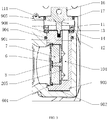
- FIG. 1 is a structural view of a multi-channel ultrasonic flowmeter of the invention
- FIG. 2 is slant sectional view of an embodiment of the multi-channel ultrasonic flowmeter
- FIG. 3 is a partially enlarged view of the installation of a transducer assembly in FIG. 2 ;
- FIG. 4 is a schematic diagram of the transducer assembly
- FIG. 5 is a partially enlarged view of a lower side of the transducer assembly
- FIG. 6 is cross-sectional view of a pipe housing.
- a multi-channel ultrasonic flowmeter comprises transducer assemblies 21 , 22 , 23 , 24 and a pipe housing 10 , wherein the transducer assembly 21 and the transducer assembly 22 are used in pairs, the transducer assembly 23 and the transducer assembly 24 are used in pairs, flanges 4 are separately arranged at two ends of the pipe housing 10 and are provided with bolt holes 41 , and a pipe is connected into the pipe housing 10 with bolts, so that the flow rate in the pipe is measured.
- four transducer assembly installation holes 9 are formed in the two ends of the pipe housing 10 close to the flanges 4 and are separately located at a left end and a right end of the pipe housing 10 .
- the transducer assembly installation holes 9 are used for installing and positioning the transducer assemblies and are arranged perpendicular to the pipe housing 10 . In order to increase the range ratio, the transducer assembly installation holes 9 should be arranged as close as possible to the flanges.
- the transducer assemblies comprise transducers 7 and stationary posts 1 , two first installation holes 103 are formed in the middle of each stationary post 1 , and the transducers 7 are installed in the first installation holes 103 .
- Each of the four transducer assemblies is provided with two transducers 7 , so that four ultrasonic channels are formed.
- comparative measurement of the fluid flow can be achieved through the four ultrasonic channels, and a more accurate flow value is obtained through arithmetic round-off and calculation, thus, improving the accuracy of the flowmeter; and on the other hand, certain transducers 7 can serve as standbys to be used when one pair of transducers cannot work normally, thus, improving the reliability of the flowmeter.
- Two or more pairs of transducers can be configured in each set to adapt to pipes having different diameters, and the laminar flow can be more accurately measured through more transducers.
- one set of the transducers can be used as standbys, so that the safety and reliability of the flowmeter are improved.
- each transducer assembly further comprises a circular compression piece 6 and an elastic steel wire ring 601 .
- Protrusions 61 extending outwards in a radial direction are symmetrically formed on a left side and a right side of each circular compression piece 6 .
- First installation faces 205 are formed in the first installation holes 103 , and the first installation holes 103 are formed with second circular grooves 132 and second rectangular grooves 131 , wherein the size of the second rectangular grooves 131 should be greater than or equal to that of the protrusions 61 .
- the elastic rings 601 are circular rings, have an outer diameter greater than that of the second circular grooves 132 in a natural state and are compressed when installed in the second circular grooves 132 .
- Bosses are arranged at transmitting ends of the transducers 7 , and the bosses are cylindrical and have a diameter smaller than or equal to an internal bore diameter of the circular compression pieces 6 .
- the other ends of the transducers 7 are attached to the first installation faces 205 , so that the transducers are accurately positioned in the axial direction.
- the circular compression pieces 6 are disposed around the transmitting ends of the transducers 7 first, the protrusions 61 are accurately placed into the second rectangular grooves 131 and are then rotated by 90° to be disposed into the second circular grooves 132 , and afterwards, the elastic rings 601 are installed in the second circular grooves 132 and press against the protrusions 61 , so that the circular compression pieces 6 and the transducers 7 are tightly pressed and fastened on the first installation faces 205 .
- first sealing gaskets 8 are arranged between the first installation faces 205 and the transducers 7 .
- the first sealing gaskets 8 are usually silica gel gaskets and can be compressed by the circular compression pieces 6 and the elastic rings 601 . The sealing effect can be improved with the increase of the pipe pressure.
- each stationary post 1 is provided with a first cylindrical body 109 located on an upper portion of the stationary post 1 , a lower portion of the stationary post 1 is provided with a key-shaped protrusion 105 extending in an axial direction, and a first positioning step surface 106 is formed between the key-shaped protrusion 105 and a body of the stationary post 1 .
- FIG. 3 and FIG. 4 each stationary post 1 is provided with a first cylindrical body 109 located on an upper portion of the stationary post 1 , a lower portion of the stationary post 1 is provided with a key-shaped protrusion 105 extending in an axial direction, and a first positioning step surface 106 is formed between the key-shaped protrusion 105 and a body of the stationary post 1 .
- each transducer assembly installation hole 9 comprises a first round hole 901 and a key groove 902 , wherein the first round hole 901 is located on an upper portion of the transducer assembly installation hole 9 , and a bottom end of the transducer assembly installation hole 9 is formed with the key groove 902 and is provided with a second positioning step surface 903 .
- the key grooves 902 are matched with the key-shaped protrusions 105 , and the maximum length of the key grooves 902 is smaller than the diameter of the first round holes 901 .
- the first round holes 901 are matched with the first cylindrical bodies 109 , and the key-shaped protrusions 105 are matched with the key grooves 902 at the same time, so that rotation of the stationary posts 1 around axes thereof is limited.
- the degree of freedom of rotation of the stationary posts 1 is limited by the key-shaped positioning protrusions 105 , so that positioning accuracy is high, rotational displacement of the stationary posts 1 is avoided, and signals can be stably transmitted and received between the transducers 7 .
- Axial positioning of the stationary posts 1 upper portions of the transducer assembly installation holes 9 are broached to form second round holes 905 , and third positioning step surfaces 908 are formed between the second round holes 905 and the first round holes 901 .
- the first positioning step surfaces 106 are attached to the second positioning step surfaces 903 of the transducer assembly installation holes 9 .
- upper end faces of the stationary posts 1 are flush with the third positioning step surfaces 908 and are compressed by compression rings 11 in threaded connection with the second round holes 905 , so that the stationary posts 1 are prevented from moving upwards or downwards around axes thereof.
- the multi-channel ultrasonic flowmeter further comprises second sealing rings 12 , polytetrafluoroethylene gaskets 14 , disc springs 13 and compression rings 11 , wherein the compression rings 11 are in threaded connection with the second round holes 905 to press the polytetrafluoroethylene gaskets 14 and the disc springs 13 against the upper end faces of the stationary posts 1 and the third positioning step surfaces 908 , the disc springs 13 are located above the polytetrafluoroethylene gaskets 14 , circular grooves 904 are formed in the first round holes 901 , and the second sealing rings 12 are arranged in the circular grooves 904 .
- the multi-channel ultrasonic flowmeter has the unique feature that the polytetrafluoroethylene gaskets 14 only seal a circular narrow gap formed between the stationary posts 1 and the corresponding faces of the first round holes 901 and are located at the center of the polytetrafluoroethylene gaskets 14 in a width direction.
- the disc springs 13 press against the polytetrafluoroethylene gaskets 14 .
- the polytetrafluoroethylene gaskets 14 can adapt to a high-temperature (up to 220° C.) and high-pressure (up to 5 PMa) condition in an alternate cooling and heating environment for a long time without aging, thereby having a service life for dozens of years.
- This sealing structure is compact and is superior to the prior art in the following aspects: the outer circumference of the upper portions of the stationary posts 1 is small, and accordingly, the transducer assembly installation holes 9 are small, so that the transducer assemblies can be arranged as close as possible to the flanges 4 , the distance from the connection wires of the transducers to the projections in the fluid flow direction are maximized under a fixed length of the pipe housing, and accordingly, the metering accuracy and range ratio of the flowmeter are improved.
- Wiring of the transducers 7 as shown in FIG. 2 , a circuit box 5 is arranged outside the pipe housing 10 , and a controller is arranged in the circuit box 5 .
- a wire hole 101 and four wiring holes 100 are formed in the pipe housing 10 , wherein the wire hole 101 is perpendicular to the pipe housing 10 , and is communicated with the circuit box 5 , and the four transducer assembly installation holes 9 are communicated with the wire hole 101 via the four wiring holes 100 .
- wire guide holes 104 are formed in the upper portions of the stationary posts 1 and are communicated with the first installation holes 103 .
- Wires of the transducers 7 are led into the wire guide holes 104 via the first installation holes 103 and finally are led out of the upper ends of the stationary posts 1 . After being led out of the upper ends of the stationary posts 1 , the wires enter the transducer assembly installation holes 9 and then enter the wire hole 101 via the wiring holes 100 to be connected to the controller in the circuit box 5 .
- the multi-channel ultrasonic flowmeter further comprises plastic covers 16 , as shown in FIG. 3 .
- the plastic covers 16 are arranged in the second round holes 905 and are located above the compression rings 11 , and first sealing rings 17 are arranged between the plastic covers 16 and the second round holes 905 .
- a cylinder convexly extending downwards is formed in the middle of each plastic cover 16 and has a tail end provided with an external thread. The cylinders are in threaded connection with threaded holes in the stationary posts 1 .
- Lead-sealed holes 161 are formed in the plastic covers 16 .
- Second lead-sealed holes 111 are formed in the pipe housing 10 .
- the plastic covers 16 are disassembled first, then the compression rings 11 are disassembled, and afterwards, the plastic covers 16 are assembled; and because the plastic covers 16 are in threaded connection with the stationary posts 1 , the plastic covers 16 and the stationary posts 1 can be taken out together by pulling the plastic covers 16 , and transducer assemblies are conveniently disassembled.
Landscapes
- Physics & Mathematics (AREA)
- Electromagnetism (AREA)
- Fluid Mechanics (AREA)
- General Physics & Mathematics (AREA)
- Measuring Volume Flow (AREA)
Applications Claiming Priority (4)
| Application Number | Priority Date | Filing Date | Title |
|---|---|---|---|
| CN201720098989.3 | 2017-01-23 | ||
| CN201720098989U | 2017-01-23 | ||
| CN201720098989.3U CN206440316U (zh) | 2017-01-23 | 2017-01-23 | 一种多通道超声波流量计 |
| PCT/CN2017/106149 WO2018133463A1 (fr) | 2017-01-23 | 2017-10-13 | Débitmètre ultrasonore multicanal |
Publications (2)
| Publication Number | Publication Date |
|---|---|
| US20190346299A1 US20190346299A1 (en) | 2019-11-14 |
| US10557733B2 true US10557733B2 (en) | 2020-02-11 |
Family
ID=59636542
Family Applications (1)
| Application Number | Title | Priority Date | Filing Date |
|---|---|---|---|
| US16/330,443 Active US10557733B2 (en) | 2017-01-23 | 2017-10-13 | Multi-channel ultrasonic flow meter |
Country Status (3)
| Country | Link |
|---|---|
| US (1) | US10557733B2 (fr) |
| CN (1) | CN206440316U (fr) |
| WO (1) | WO2018133463A1 (fr) |
Cited By (1)
| Publication number | Priority date | Publication date | Assignee | Title |
|---|---|---|---|---|
| US20210048325A1 (en) * | 2019-08-15 | 2021-02-18 | Spire Metering Technology LLC | Ultrasonic flow meter |
Families Citing this family (5)
| Publication number | Priority date | Publication date | Assignee | Title |
|---|---|---|---|---|
| CN206440316U (zh) * | 2017-01-23 | 2017-08-25 | 青岛海威茨仪表有限公司 | 一种多通道超声波流量计 |
| US11215488B2 (en) * | 2019-07-02 | 2022-01-04 | Itron Global Sarl | Transducer enclosure with variable moisture proofing |
| USD953180S1 (en) * | 2020-06-11 | 2022-05-31 | Dwyer Instruments, Inc. | Differential pressure transmitter |
| CN114111952A (zh) * | 2021-11-22 | 2022-03-01 | 金卡智能集团股份有限公司 | 表头连接件及流量计 |
| CN117553869A (zh) * | 2022-08-03 | 2024-02-13 | 金卡智能集团股份有限公司 | 超声波流量计 |
Citations (31)
| Publication number | Priority date | Publication date | Assignee | Title |
|---|---|---|---|---|
| US20080307911A1 (en) * | 2007-06-15 | 2008-12-18 | Daniel Measurement And Control, Inc. | Cable Cover for an Ultrasonic Flow Meter |
| US20100005901A1 (en) * | 2008-07-09 | 2010-01-14 | Daniel Measurement And Control, Inc. | Method and system of coordination of measurement subsystems of a flow meter |
| US20100242590A1 (en) * | 2009-03-27 | 2010-09-30 | Daniel Measurement And Control, Inc. | Flow Meter and Temperature Stabilizing Cover Therefor |
| US20110162463A1 (en) * | 2010-01-06 | 2011-07-07 | Daniel Measurement And Control, Inc. | Ultrasonic Flow Meter Having A Port Cover Assembly |
| JP4793916B2 (ja) | 2005-11-18 | 2011-10-12 | リコーエレメックス株式会社 | 超音波流量計のセンサ取付構造 |
| CN202420578U (zh) | 2012-01-19 | 2012-09-05 | 唐山汇中仪表股份有限公司 | 一种多声路超声水表、热量表用测量管段 |
| US20130098167A1 (en) * | 2011-10-24 | 2013-04-25 | General Electric Company | Flow cell for a flow meter |
| US20130219707A1 (en) * | 2012-02-29 | 2013-08-29 | General Electric Company | Sensor port insert apparatus |
| US20130294475A1 (en) * | 2012-05-02 | 2013-11-07 | Daniel Measurement And Control, Inc. | Temperature verification for ultrasonic flow meters |
| US20130291649A1 (en) * | 2012-05-02 | 2013-11-07 | Daniel Measurement And Control, Inc. | System and method for meter substitution for co-located flowmeters |
| US20140083181A1 (en) * | 2012-09-25 | 2014-03-27 | General Electric Company | Removable sensor port insert apparatus |
| US20140103274A1 (en) * | 2012-10-15 | 2014-04-17 | General Electric Company | Apparatus and method for installing or removing a cable |
| US20140109687A1 (en) * | 2012-10-19 | 2014-04-24 | Daniel Measurement And Control, Inc. | Quantitative analysis of flow profile characteristics for ultrasonic metering systems |
| US20140111342A1 (en) * | 2012-10-19 | 2014-04-24 | Daniel Measurement And Control, Inc. | Condition monitoring with alarm confidence levels for flow metering systems |
| US20140109686A1 (en) * | 2012-10-19 | 2014-04-24 | Daniel Measurement And Control, Inc. | Ultrasonic flow metering system with an upstream pressure transducer |
| US20140109645A1 (en) * | 2012-10-19 | 2014-04-24 | Daniel Measurement And Control, Inc. | Determination of reference values for ultrasonic flow metering systems |
| US20140109689A1 (en) * | 2012-10-19 | 2014-04-24 | Daniel Measurement And Control, Inc. | Percentage deviation based evaluation of velocity dependent characteristics in ultrasonic flow metering systems |
| US20140109690A1 (en) * | 2012-10-19 | 2014-04-24 | Daniel Measurement And Control, Inc. | Reynolds number based verification for ultrasonic flow metering systems |
| CN103868628A (zh) | 2012-12-18 | 2014-06-18 | 杭州三花研究院有限公司 | 一种超声波热量表 |
| US8776613B2 (en) * | 2010-03-18 | 2014-07-15 | Sick Engineering Gmbh | Ultrasonic measurement apparatus having a deflection unit forming a loop |
| US20140238148A1 (en) * | 2013-02-27 | 2014-08-28 | Daniel Measurement And Control, Inc. | Ultrasonic flow metering with laminar to turbulent transition flow control |
| US20140260670A1 (en) * | 2013-03-15 | 2014-09-18 | Dieterich Standard, Inc. | Process variable measurement using primary element connection platform |
| US20150000420A1 (en) * | 2012-09-07 | 2015-01-01 | Daniel Measurement And Control, Inc. | Ultrasonic flow metering using compensated computed temperature |
| CN204313901U (zh) | 2015-01-05 | 2015-05-06 | 上海迪纳声科技股份有限公司 | 多声路超声水表、热量表用测量管段 |
| US20150136842A1 (en) * | 2012-07-18 | 2015-05-21 | Daniel Measurement And Control, Inc. | Method for Forming a Welded Seal |
| US20150268077A1 (en) * | 2014-03-20 | 2015-09-24 | Daniel Measurement And Control, Inc. | Transducer for ultrasonic flow meter |
| CN205537791U (zh) | 2016-04-18 | 2016-08-31 | 汇中仪表股份有限公司 | 一种具有防冻功能的超声流量、热量计用测量传感器结构 |
| US20160282160A1 (en) * | 2015-03-24 | 2016-09-29 | Daniel Measurement And Control, Inc. | Transducer mini-horn array for ultrasonic flow meter |
| CN206440316U (zh) | 2017-01-23 | 2017-08-25 | 青岛海威茨仪表有限公司 | 一种多通道超声波流量计 |
| US20190128714A1 (en) * | 2017-10-27 | 2019-05-02 | Daniel Measurement And Control, Inc. | Adjustable Transducer Assemblies |
| US20190186967A1 (en) * | 2017-12-19 | 2019-06-20 | Daniel Measurement And Control, Inc. | Multi-fluid calibration |
-
2017
- 2017-01-23 CN CN201720098989.3U patent/CN206440316U/zh active Active
- 2017-10-13 WO PCT/CN2017/106149 patent/WO2018133463A1/fr active Application Filing
- 2017-10-13 US US16/330,443 patent/US10557733B2/en active Active
Patent Citations (31)
| Publication number | Priority date | Publication date | Assignee | Title |
|---|---|---|---|---|
| JP4793916B2 (ja) | 2005-11-18 | 2011-10-12 | リコーエレメックス株式会社 | 超音波流量計のセンサ取付構造 |
| US20080307911A1 (en) * | 2007-06-15 | 2008-12-18 | Daniel Measurement And Control, Inc. | Cable Cover for an Ultrasonic Flow Meter |
| US20100005901A1 (en) * | 2008-07-09 | 2010-01-14 | Daniel Measurement And Control, Inc. | Method and system of coordination of measurement subsystems of a flow meter |
| US20100242590A1 (en) * | 2009-03-27 | 2010-09-30 | Daniel Measurement And Control, Inc. | Flow Meter and Temperature Stabilizing Cover Therefor |
| US20110162463A1 (en) * | 2010-01-06 | 2011-07-07 | Daniel Measurement And Control, Inc. | Ultrasonic Flow Meter Having A Port Cover Assembly |
| US8776613B2 (en) * | 2010-03-18 | 2014-07-15 | Sick Engineering Gmbh | Ultrasonic measurement apparatus having a deflection unit forming a loop |
| US20130098167A1 (en) * | 2011-10-24 | 2013-04-25 | General Electric Company | Flow cell for a flow meter |
| CN202420578U (zh) | 2012-01-19 | 2012-09-05 | 唐山汇中仪表股份有限公司 | 一种多声路超声水表、热量表用测量管段 |
| US20130219707A1 (en) * | 2012-02-29 | 2013-08-29 | General Electric Company | Sensor port insert apparatus |
| US20130294475A1 (en) * | 2012-05-02 | 2013-11-07 | Daniel Measurement And Control, Inc. | Temperature verification for ultrasonic flow meters |
| US20130291649A1 (en) * | 2012-05-02 | 2013-11-07 | Daniel Measurement And Control, Inc. | System and method for meter substitution for co-located flowmeters |
| US20150136842A1 (en) * | 2012-07-18 | 2015-05-21 | Daniel Measurement And Control, Inc. | Method for Forming a Welded Seal |
| US20150000420A1 (en) * | 2012-09-07 | 2015-01-01 | Daniel Measurement And Control, Inc. | Ultrasonic flow metering using compensated computed temperature |
| US20140083181A1 (en) * | 2012-09-25 | 2014-03-27 | General Electric Company | Removable sensor port insert apparatus |
| US20140103274A1 (en) * | 2012-10-15 | 2014-04-17 | General Electric Company | Apparatus and method for installing or removing a cable |
| US20140109686A1 (en) * | 2012-10-19 | 2014-04-24 | Daniel Measurement And Control, Inc. | Ultrasonic flow metering system with an upstream pressure transducer |
| US20140111342A1 (en) * | 2012-10-19 | 2014-04-24 | Daniel Measurement And Control, Inc. | Condition monitoring with alarm confidence levels for flow metering systems |
| US20140109690A1 (en) * | 2012-10-19 | 2014-04-24 | Daniel Measurement And Control, Inc. | Reynolds number based verification for ultrasonic flow metering systems |
| US20140109687A1 (en) * | 2012-10-19 | 2014-04-24 | Daniel Measurement And Control, Inc. | Quantitative analysis of flow profile characteristics for ultrasonic metering systems |
| US20140109645A1 (en) * | 2012-10-19 | 2014-04-24 | Daniel Measurement And Control, Inc. | Determination of reference values for ultrasonic flow metering systems |
| US20140109689A1 (en) * | 2012-10-19 | 2014-04-24 | Daniel Measurement And Control, Inc. | Percentage deviation based evaluation of velocity dependent characteristics in ultrasonic flow metering systems |
| CN103868628A (zh) | 2012-12-18 | 2014-06-18 | 杭州三花研究院有限公司 | 一种超声波热量表 |
| US20140238148A1 (en) * | 2013-02-27 | 2014-08-28 | Daniel Measurement And Control, Inc. | Ultrasonic flow metering with laminar to turbulent transition flow control |
| US20140260670A1 (en) * | 2013-03-15 | 2014-09-18 | Dieterich Standard, Inc. | Process variable measurement using primary element connection platform |
| US20150268077A1 (en) * | 2014-03-20 | 2015-09-24 | Daniel Measurement And Control, Inc. | Transducer for ultrasonic flow meter |
| CN204313901U (zh) | 2015-01-05 | 2015-05-06 | 上海迪纳声科技股份有限公司 | 多声路超声水表、热量表用测量管段 |
| US20160282160A1 (en) * | 2015-03-24 | 2016-09-29 | Daniel Measurement And Control, Inc. | Transducer mini-horn array for ultrasonic flow meter |
| CN205537791U (zh) | 2016-04-18 | 2016-08-31 | 汇中仪表股份有限公司 | 一种具有防冻功能的超声流量、热量计用测量传感器结构 |
| CN206440316U (zh) | 2017-01-23 | 2017-08-25 | 青岛海威茨仪表有限公司 | 一种多通道超声波流量计 |
| US20190128714A1 (en) * | 2017-10-27 | 2019-05-02 | Daniel Measurement And Control, Inc. | Adjustable Transducer Assemblies |
| US20190186967A1 (en) * | 2017-12-19 | 2019-06-20 | Daniel Measurement And Control, Inc. | Multi-fluid calibration |
Cited By (2)
| Publication number | Priority date | Publication date | Assignee | Title |
|---|---|---|---|---|
| US20210048325A1 (en) * | 2019-08-15 | 2021-02-18 | Spire Metering Technology LLC | Ultrasonic flow meter |
| US11566928B2 (en) * | 2019-08-15 | 2023-01-31 | Spire Metering Technology LLC | Ultrasonic flow meter having four separate transducer assemblies mounted within mounts in a flow cell |
Also Published As
| Publication number | Publication date |
|---|---|
| US20190346299A1 (en) | 2019-11-14 |
| WO2018133463A1 (fr) | 2018-07-26 |
| CN206440316U (zh) | 2017-08-25 |
Similar Documents
| Publication | Publication Date | Title |
|---|---|---|
| US10557733B2 (en) | Multi-channel ultrasonic flow meter | |
| US4672728A (en) | Pressure signal instrumentation having removable flanges and mounting method therefor | |
| RU2532611C2 (ru) | Способ и система преобразовательного блока ультразвукового расходомера | |
| US20210003435A1 (en) | Small-diameter ultrasonic flow meter having opposing transducers | |
| CN204269166U (zh) | 晶片型电磁流量传感器 | |
| CN106017787A (zh) | 一种防腐压力传感器 | |
| CN104913821A (zh) | 电磁流量计 | |
| CN212843771U (zh) | 一种物联网超声波流量计换能器密封装置 | |
| GB2391278A (en) | Pipe Coupling | |
| CN114110248A (zh) | 一种计量监测型闸阀 | |
| CN217331270U (zh) | 一种非接触式流量测量系统 | |
| CN113390021A (zh) | 一种管道法兰(盲法兰)泄漏监测设备及使用方法 | |
| JP5569970B2 (ja) | 電磁式水道メーター | |
| CN219092637U (zh) | 一种超声换能器结构 | |
| US8177238B2 (en) | System and method of a flange seal ring | |
| CN218496171U (zh) | 一种法兰取压流量测量装置 | |
| CN117906770A (zh) | 传感器的安装结构 | |
| JP6428239B2 (ja) | 電磁流量計 | |
| RU2110771C1 (ru) | Устройство для измерения расхода текучих сред | |
| CN220690189U (zh) | 一种超声波水表基表结构 | |
| CN211602049U (zh) | 内衬式超声波流量计用固定安装结构 | |
| KR20150114192A (ko) | 고무확장조인트에 대한 내압성능 시험장치 및 그 제조방법 | |
| CN220082384U (zh) | 一种天然气管道固定机构 | |
| CN113567137B (zh) | 一种薄壁式冷却孔液流检测装置及方法 | |
| CN213956479U (zh) | 一种皮托尔流量计 |
Legal Events
| Date | Code | Title | Description |
|---|---|---|---|
| AS | Assignment |
Owner name: LI, XINXING, CHINA Free format text: ASSIGNMENT OF ASSIGNORS INTEREST;ASSIGNORS:FANG, XIN;LI, XINXING;REEL/FRAME:048502/0050 Effective date: 20190303 |
|
| FEPP | Fee payment procedure |
Free format text: ENTITY STATUS SET TO UNDISCOUNTED (ORIGINAL EVENT CODE: BIG.); ENTITY STATUS OF PATENT OWNER: MICROENTITY |
|
| AS | Assignment |
Owner name: QINGDAO HIWITS METER CO., LTD., CHINA Free format text: ASSIGNMENT OF ASSIGNORS INTEREST;ASSIGNOR:LI, XINXING;REEL/FRAME:048615/0106 Effective date: 20190311 |
|
| FEPP | Fee payment procedure |
Free format text: ENTITY STATUS SET TO MICRO (ORIGINAL EVENT CODE: MICR); ENTITY STATUS OF PATENT OWNER: MICROENTITY |
|
| STPP | Information on status: patent application and granting procedure in general |
Free format text: RESPONSE TO NON-FINAL OFFICE ACTION ENTERED AND FORWARDED TO EXAMINER |
|
| FEPP | Fee payment procedure |
Free format text: ENTITY STATUS SET TO MICRO (ORIGINAL EVENT CODE: MICR); ENTITY STATUS OF PATENT OWNER: MICROENTITY |
|
| STPP | Information on status: patent application and granting procedure in general |
Free format text: PUBLICATIONS -- ISSUE FEE PAYMENT VERIFIED |
|
| STCF | Information on status: patent grant |
Free format text: PATENTED CASE |
|
| MAFP | Maintenance fee payment |
Free format text: PAYMENT OF MAINTENANCE FEE, 4TH YEAR, MICRO ENTITY (ORIGINAL EVENT CODE: M3551); ENTITY STATUS OF PATENT OWNER: MICROENTITY Year of fee payment: 4 |