US10556263B2 - Deformation Method and Press - Google Patents
Deformation Method and Press Download PDFInfo
- Publication number
- US10556263B2 US10556263B2 US15/562,715 US201615562715A US10556263B2 US 10556263 B2 US10556263 B2 US 10556263B2 US 201615562715 A US201615562715 A US 201615562715A US 10556263 B2 US10556263 B2 US 10556263B2
- Authority
- US
- United States
- Prior art keywords
- press
- lever
- ram
- knuckle
- piston
- Prior art date
- Legal status (The legal status is an assumption and is not a legal conclusion. Google has not performed a legal analysis and makes no representation as to the accuracy of the status listed.)
- Expired - Fee Related, expires
Links
Images


Classifications
-
- B—PERFORMING OPERATIONS; TRANSPORTING
- B21—MECHANICAL METAL-WORKING WITHOUT ESSENTIALLY REMOVING MATERIAL; PUNCHING METAL
- B21D—WORKING OR PROCESSING OF SHEET METAL OR METAL TUBES, RODS OR PROFILES WITHOUT ESSENTIALLY REMOVING MATERIAL; PUNCHING METAL
- B21D22/00—Shaping without cutting, by stamping, spinning, or deep-drawing
- B21D22/02—Stamping using rigid devices or tools
- B21D22/022—Stamping using rigid devices or tools by heating the blank or stamping associated with heat treatment
-
- B—PERFORMING OPERATIONS; TRANSPORTING
- B21—MECHANICAL METAL-WORKING WITHOUT ESSENTIALLY REMOVING MATERIAL; PUNCHING METAL
- B21D—WORKING OR PROCESSING OF SHEET METAL OR METAL TUBES, RODS OR PROFILES WITHOUT ESSENTIALLY REMOVING MATERIAL; PUNCHING METAL
- B21D26/00—Shaping without cutting otherwise than using rigid devices or tools or yieldable or resilient pads, i.e. applying fluid pressure or magnetic forces
- B21D26/02—Shaping without cutting otherwise than using rigid devices or tools or yieldable or resilient pads, i.e. applying fluid pressure or magnetic forces by applying fluid pressure
- B21D26/033—Deforming tubular bodies
- B21D26/039—Means for controlling the clamping or opening of the moulds
-
- B—PERFORMING OPERATIONS; TRANSPORTING
- B21—MECHANICAL METAL-WORKING WITHOUT ESSENTIALLY REMOVING MATERIAL; PUNCHING METAL
- B21J—FORGING; HAMMERING; PRESSING METAL; RIVETING; FORGE FURNACES
- B21J9/00—Forging presses
- B21J9/10—Drives for forging presses
- B21J9/12—Drives for forging presses operated by hydraulic or liquid pressure
-
- B—PERFORMING OPERATIONS; TRANSPORTING
- B22—CASTING; POWDER METALLURGY
- B22D—CASTING OF METALS; CASTING OF OTHER SUBSTANCES BY THE SAME PROCESSES OR DEVICES
- B22D17/00—Pressure die casting or injection die casting, i.e. casting in which the metal is forced into a mould under high pressure
- B22D17/20—Accessories: Details
- B22D17/26—Mechanisms or devices for locking or opening dies
-
- B—PERFORMING OPERATIONS; TRANSPORTING
- B29—WORKING OF PLASTICS; WORKING OF SUBSTANCES IN A PLASTIC STATE IN GENERAL
- B29C—SHAPING OR JOINING OF PLASTICS; SHAPING OF MATERIAL IN A PLASTIC STATE, NOT OTHERWISE PROVIDED FOR; AFTER-TREATMENT OF THE SHAPED PRODUCTS, e.g. REPAIRING
- B29C59/00—Surface shaping of articles, e.g. embossing; Apparatus therefor
- B29C59/002—Component parts, details or accessories; Auxiliary operations
-
- B—PERFORMING OPERATIONS; TRANSPORTING
- B29—WORKING OF PLASTICS; WORKING OF SUBSTANCES IN A PLASTIC STATE IN GENERAL
- B29C—SHAPING OR JOINING OF PLASTICS; SHAPING OF MATERIAL IN A PLASTIC STATE, NOT OTHERWISE PROVIDED FOR; AFTER-TREATMENT OF THE SHAPED PRODUCTS, e.g. REPAIRING
- B29C59/00—Surface shaping of articles, e.g. embossing; Apparatus therefor
- B29C59/02—Surface shaping of articles, e.g. embossing; Apparatus therefor by mechanical means, e.g. pressing
-
- B—PERFORMING OPERATIONS; TRANSPORTING
- B30—PRESSES
- B30B—PRESSES IN GENERAL
- B30B1/00—Presses, using a press ram, characterised by the features of the drive therefor, pressure being transmitted directly, or through simple thrust or tension members only, to the press ram or platen
- B30B1/02—Presses, using a press ram, characterised by the features of the drive therefor, pressure being transmitted directly, or through simple thrust or tension members only, to the press ram or platen by lever mechanism
- B30B1/08—Presses, using a press ram, characterised by the features of the drive therefor, pressure being transmitted directly, or through simple thrust or tension members only, to the press ram or platen by lever mechanism operated by fluid-pressure means
-
- B—PERFORMING OPERATIONS; TRANSPORTING
- B30—PRESSES
- B30B—PRESSES IN GENERAL
- B30B1/00—Presses, using a press ram, characterised by the features of the drive therefor, pressure being transmitted directly, or through simple thrust or tension members only, to the press ram or platen
- B30B1/10—Presses, using a press ram, characterised by the features of the drive therefor, pressure being transmitted directly, or through simple thrust or tension members only, to the press ram or platen by toggle mechanism
- B30B1/106—Presses, using a press ram, characterised by the features of the drive therefor, pressure being transmitted directly, or through simple thrust or tension members only, to the press ram or platen by toggle mechanism operated by another toggle mechanism
-
- B—PERFORMING OPERATIONS; TRANSPORTING
- B30—PRESSES
- B30B—PRESSES IN GENERAL
- B30B1/00—Presses, using a press ram, characterised by the features of the drive therefor, pressure being transmitted directly, or through simple thrust or tension members only, to the press ram or platen
- B30B1/10—Presses, using a press ram, characterised by the features of the drive therefor, pressure being transmitted directly, or through simple thrust or tension members only, to the press ram or platen by toggle mechanism
- B30B1/16—Presses, using a press ram, characterised by the features of the drive therefor, pressure being transmitted directly, or through simple thrust or tension members only, to the press ram or platen by toggle mechanism operated by fluid-pressure means
-
- B—PERFORMING OPERATIONS; TRANSPORTING
- B30—PRESSES
- B30B—PRESSES IN GENERAL
- B30B15/00—Details of, or accessories for, presses; Auxiliary measures in connection with pressing
- B30B15/0029—Details of, or accessories for, presses; Auxiliary measures in connection with pressing means for adjusting the space between the press slide and the press table, i.e. the shut height
Definitions
- the invention is directed to a forming process, particularly a hot-forming process, and to a press in which there is provided in a frame a ram closing through the force of a cylinder with a moveable piston against a press table in a straight-line movement.
- Hydraulically operated presses in particular have a broad spectrum of application.
- Mechanically operated presses on the other hand, are often of a specific nature. Thus mechanically operated knuckle joint presses are usually only used in book printing or as fruit presses.
- the forming process according to one aspect of the invention has a number of advantages which are based on dividing the forming of a workpiece into two forming portions. Accordingly, a fast closing process of the press is initiated through the transference of the force of the cylinder to the at least one knuckle joint system. If the knuckle joint system is then extended and the ram can be supported against the frame, the forming process is concluded through the hydraulic cushion of the ram under high force.
- a further advantage results from the step in which the hydraulic cushion is initially moved out during the closing of the press, the hydraulic cushion is moved in with impingement on a workpiece, and after extension of the at least one knuckle joint system the hydraulic cushion, which moves out again, concludes the forming process.
- hydraulic fluid is displaced from the cylinder of the hydraulic cushion, and only a small amount of hydraulic fluid need then impinge upon the hydraulic cushion after extension of the at least one knuckle joint system.
- the advantages are realized when it is provided that the ram is connected so as to be fixed with respect to the frame via at least two identically constructed knuckle joint systems and that the ram has a hydraulic cushion.
- the press according to aspects of the invention likewise has a number of advantages.
- initial closing speeds of the knuckle joint systems of 800 mm/s to 900 mm/s can be achieved.
- the control of the one cylinder can be kept simple because the knuckle levers are connected in parallel and a deformation during the pressing process can be ruled out to a great extent through a sufficient dimensioning or a sufficient quantity of knuckle joint systems.
- a very uniform pressure can also be worked up via the ram through the arrangement of and/or the quantity of knuckle levers.
- the knuckle joint systems When the knuckle joint systems are extended and can accordingly, through their extension, transmit high forces to the frame of the press, the concluding forming of a workpiece takes place through the moving out of the hydraulic cushion which, to this end, can have, e.g., six hydraulic cylinders so as to be adapted to the stated object.
- a knuckle joint system has a lever which is connected at a first end via a first rotational axis to the ram, that a T-shaped knuckle lever is connected at one end of the continuous leg to the second end of the lever via a second rotational axis, that the continuous leg is connected at the other end via a third rotational axis in a receptacle which is fixed with respect to the frame, and the three rotational axes lie in a line in movement direction of the ram in the closed position of the press, and that the free end of the extending leg of the knuckle lever is connected at one end via a fourth rotational axis to a connection lever, which is connected at the other end to the one piston via a fifth rotational axis.
- the height of the receptacles over the press table is adjustable.
- a correspondingly constructed long cylinder and the vertical adjustability thereof make it possible to adapt to workpieces and dies of different dimensions in a simple manner.
- the receptacles are arranged at the free ends of threaded spindles, particularly with a trapezoidal thread, which extend in movement direction of the ram. They can then be fixed in spindle nuts, e.g., in a top flange of the frame joining two uprights, so as to be adjustable with respect to height and, e.g., can be actuated by motor. A hydraulic locking mechanism can then secure the height adjustment.
- the geometry of the knuckle joint system aims primarily at a fast closing of the press. Therefore, it is provided that the distances between the first rotational axis and the second rotational axis and between the second rotational axis and the third rotational axis are equal. Accordingly, these lever portions form an isosceles triangle when the press is open. In a corresponding manner, uniform loads also take place during a closing of the press.
- the step by which the second rotational axis and the fourth rotational axis are arranged on a circular path around the third rotational axis can also be useful for this purpose.
- At least three knuckle joint systems are arranged so as to have uniform pitch on a circular path centrally over the hydraulic cushion, which is possibly circular in cross section, with inwardly directed, extending legs of the knuckle levers, and that the free ends of the knuckle levers are connected via the connection lever to a common platform fixed with respect to the piston.
- At least two knuckle joint systems arranged with extending legs of the knuckle levers directed towards one another over the ram, and the free ends of the extending legs of the knuckle levers are connected via the connection lever to a common platform which is fixed with respect to the piston. If four knuckle joint systems are intended, they are arranged in two pairs extending adjacent to one another.
- An arrangement of this kind is used with comparatively large rectangular hydraulic cushions, in which case the application of the knuckle joint systems takes place in the corners of the hydraulic cushion.
- connection levers Regardless of the arrangement of the knuckle joint systems, it is provided that webs to which the connection levers are rotatably connected project from the underside of the platform.
- the webs will extend in a star-shaped manner and intersect in the center of the platform. In case of four knuckle levers, two parallel webs are to be provided.
- levers are formed by double levers.
- connections between levers, receptacles and/or webs are formed in a pincer-like manner in that a first part to be connected is enclosed by two brackets of the second part which is partially U-shaped in cross section, and in that the two parts are connected by a pin in aligned bore holes as rotational axis.
- one end of the first portion is weakened to form a neck and is provided with a rounding, that two flat sides extending perpendicular to the neck are formed by the weakening, that the front sides of the rounded brackets of the second portion lie on the flat sides in the closed position of the press, and that, during an opening or closing of the press and a resulting deflection of the portions toward one another, the roundings of the brackets roll on the flat sides and the roundings of the necks roll on the groove base formed by the brackets and/or roundings on surfaces which are fixed with respect to the piston or with respect to the ram.
- FIG. 1 is a front view of a press according to the invention
- FIG. 2 is a side view
- FIG. 3 is a top view
- FIG. 4 is an isometric diagram
- FIG. 5 is a front view of a lever shown in isolation
- FIG. 6 is a side view
- FIG. 7 is an isometric diagram
- FIG. 8 is an isometric diagram of a knuckle lever
- FIG. 9 is a front view
- FIG. 10 is a side view
- FIG. 11 is a front view of a deflected knuckle joint system
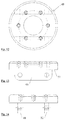
- FIG. 12 is a top view of a platform
- FIG. 13 is a first side view
- FIG. 14 is a second side view
- FIG. 15 is a front view of an opened press
- FIG. 16 is the upper die impinging on a workpiece during the closing of the press
- FIG. 17 is the press with locked knuckle joint systems and with inner box of the hydraulic cushion moved in;
- FIG. 18 is the position of the press after the conclusion of the forming process
- FIG. 19 is a side view of a hydraulic cushion
- FIG. 20 is a top view
- FIG. 21 is a front-side view
- FIG. 22 is an isometric view
- FIG. 23 is a front view with a hydraulic cushion in a bottommost position
- FIG. 24 is a front view with a hydraulic cushion in a topmost position
- FIG. 25 is a schematic view of the connection of a threaded spindle to the upper flange.
- FIG. 26 is a detail of a knuckle joint system.
- a press 1 according to one aspect of the invention is shown in a view from three sides in FIGS. 1-3 .
- the press 1 has a portal-type construction, conventional per se, with two uprights 2 , 3 and an upper flange 4 of a press frame connecting the uprights 2 , 3 .
- FIG. 1 shows the press 1 in a closed position in which an upper die 5 of a ram 6 is moved against a lower die 7 of a press table.
- a hydraulic cylinder 8 which is fixed in the upper flange 4 , is provided for adjusting the ram 6 , the piston 9 thereof acting on identically constructed knuckle joint systems 10 , 11 , of which there are four in this instance, see FIGS. 15-18 .
- a comparatively long double-cylinder which is designed for very fast stroke movements is preferably used as cylinder 8 so that the dies 5 , 7 can be closed quickly particularly for hot-forming of a workpiece via the knuckle joint systems 10 , 11 .
- the ram 6 further has a two-housing hydraulic cushion 14 at the underside of which the upper die 5 is fixed.
- FIG. 1 shows the hydraulic cushion 14 moved out, and the upper die 5 is therefore in its bottommost position.
- Every knuckle joint system 10 , 11 has a first lever 15 which is connected at a first end 16 , in this instance a lower end 16 , to the hydraulic cushion 14 of the ram 6 via a rotational axis 17 .
- the first end 16 of lever 15 has a U-shaped cross section, see FIGS. 5-7 , so that two brackets 18 , 19 with aligned bore holes 20 , 21 can enclose a neck 22 which projects from the top side of the hydraulic cushion 14 and which has a further bore hole so as to be connected through an inserted pin as rotational axis 17 , see FIG. 11 .
- this end 23 is weakened to form a neck 32 viewed from the side according to FIG. 6 and is provided with a bore hole 26 .
- the neck 32 is enclosed by two brackets 27 , 28 of the continuous leg 29 of knuckle lever 25 , which likewise again have aligned bore holes 30 , 31 .
- the lever 15 and the knuckle lever 25 are connected to one another in an articulated manner by a pin inserted into the aligned bore holes 26 , 30 , 31 as rotational axis 35 .
- the other end 34 of the continuous leg 29 of knuckle lever 25 is again weakened to form a neck 36 and is provided with a bore hole 37 for connecting so as to be fixed with respect to the frame.
- the neck 36 is enclosed by two brackets with aligned bore holes of a receptacle 38 , and a connection is carried out by a pin as rotational axis 39 .
- Brackets 41 , 42 which are provided with aligned bore holes 43 , 44 , are formed by the extending leg 40 of knuckle lever 25 .
- the brackets 41 , 42 enclose a neck 45 of a connection lever 46 with a corresponding bore hole, and the articulated connection is carried out via a pin as rotational axis 47 .
- connection lever 46 connected to the extending leg 40 of knuckle lever 25 also encloses a web 48 in the manner described above by two brackets in a pincer-like manner, which web 48 projects from the underside of a platform 49 fixed with respect to the piston, and the connection lever 46 is swivelably connected to this web 48 via a pin as rotational axis 50 .
- the common platform 49 has two parallel webs 48 , 52 projecting from the underside 51 as is shown again in FIGS. 12 to 14 .
- the knuckle joint systems are arranged so as to have a uniform pitch on a circular path centrally above the hydraulic cushion with inwardly directed, extending legs of the knuckle levers, the webs intersect in the center on the underside of the platform.
- FIG. 11 in particular shows that the connections of levers 15 , 25 , 46 are adapted to one another at the ends so as to fit precisely.
- the front sides 55 , 56 of the brackets 27 , 28 of knuckle lever 25 are supported on the front flat sides 57 , 58 of the lever 15 that extend perpendicular to the neck 32 .
- the corners of the brackets 27 , 28 are provided with roundings 59 , 60 which roll when swiveled on the flat sides 49 , 50 of the lever 15 .
- the front side 61 is supported at the upper end 16 of the lever 15 on the groove base 62 between the brackets 55 , 56 of the knuckle lever 25 , and the front side 61 is provided with a rounding 63 rolling on the groove base 62 for swiveling.
- connection of the knuckle lever 25 to the receptacle 38 and connection lever 46 , respectively, is carried out in an identical manner.
- connection of the lower end 16 of the lever 15 to the neck 22 is also comparable.
- the front sides 64 , 65 of the brackets 18 , 19 are supported on correspondingly constructed surfaces 66 of the hydraulic cushion 14 and can roll on the latter during a deflection owing to the roundings 67 , 68 .
- connection lever 46 This also applies correspondingly to the connection of the connection lever 46 to the web 48 .
- connection lever 46 for example, locks as a result of its narrow side 69 contacting the underside 51 of the platform 49 .
- levers 15 , 25 can only be deflected toward the right, only in FIG. 1 , in direction of the extending lever 40 .
- FIG. 26 shows that the distances a, a between the first rotational axis 75 of lever 76 and the second rotational axis 77 and between this rotational axis 77 and the third rotational axis 78 of knuckle lever 79 are equal in knuckle joint system 11 .
- the second rotational axis 77 and the fourth rotational axis 80 via which the extending leg 81 of knuckle lever 79 is connected to the connection lever not shown in FIG. 26 lie on a circular path r around the third rotational axis 78 .
- the three rotational axes 75 , 77 , 78 lie on a line b when dies 5 , 7 are closed.
- Receptacles 38 , 85 are adjustable in height (see FIGS. 23, 24 ) for adapting to workpieces and dies 5 , 7 of different sizes. Height adjustability may also be considered with respect to cylinder 8 , but height adjustability of this kind is not compulsory provided the stroke of the cylinder 8 is sufficiently large.
- the latter are arranged at the free end of threaded spindles 86 , 87 , preferably with a trapezoidal thread, which are engaged in the upper flange 4 so as to be adjustable in height.
- the threaded spindles 86 , 87 are guided in two spindle nuts 88 , 89 , shown in an implied manner, which enclose the upper flange 4 .
- the vertical adjustment of threaded spindle 86 is carried by two motors 90 , 91 , for example, very accurately controllable stepping motors.
- the hydraulic cushion 14 can be moved out of a lower position shown in FIG. 23 into an upper position shown in FIG. 24 in which the threaded spindles 86 , 87 project upward from the upper flange 4 .
- FIG. 25 shows that the forces occurring when the hydraulic cushion 14 is closed at the conclusion of the forming process are transmitted into the upper flange 4 solely along the lower spindle nuts 89 with extended knuckle joint systems 10 , 11 . A loading of the cylinder 8 does not take place.
- FIG. 15 shows the press 1 with knuckle levers 10 , 11 shortened as far as possible over a workpiece 95 . Therefore, the hydraulic cushion 14 is in a topmost position over the workpiece 95 .
- the hydraulic cushion 14 (see also FIGS. 19-22 ) has an outer box 96 in which an inner box 97 is guided.
- an inner box 97 For guiding, beveled inner corners 98 of the outer box 96 and beveled outer corners 99 of the inner box 97 are indicated in FIG. 20 .
- additional guide strips and grooves can be provided.
- six cylinders 100 are shown arranged between the cover 101 of the outer box 96 and the base 102 of the inner box 97 .
- the cylinders 100 according to FIG. 15 are moved out. Therefore, the upper die 5 is not in its topmost position.
Landscapes
- Engineering & Computer Science (AREA)
- Mechanical Engineering (AREA)
- Physics & Mathematics (AREA)
- Thermal Sciences (AREA)
- Fluid Mechanics (AREA)
- Press Drives And Press Lines (AREA)
- Presses And Accessory Devices Thereof (AREA)
- Shaping Metal By Deep-Drawing, Or The Like (AREA)
Abstract
Description
Claims (10)
Applications Claiming Priority (4)
| Application Number | Priority Date | Filing Date | Title |
|---|---|---|---|
| DE102015004108.8A DE102015004108A1 (en) | 2015-03-31 | 2015-03-31 | Forming process and press |
| DE102015004108 | 2015-03-31 | ||
| DE102015004108.8 | 2015-03-31 | ||
| PCT/DE2016/000076 WO2016155689A1 (en) | 2015-03-31 | 2016-02-24 | Deformation method and press |
Publications (2)
| Publication Number | Publication Date |
|---|---|
| US20180117654A1 US20180117654A1 (en) | 2018-05-03 |
| US10556263B2 true US10556263B2 (en) | 2020-02-11 |
Family
ID=55701644
Family Applications (1)
| Application Number | Title | Priority Date | Filing Date |
|---|---|---|---|
| US15/562,715 Expired - Fee Related US10556263B2 (en) | 2015-03-31 | 2016-02-24 | Deformation Method and Press |
Country Status (7)
| Country | Link |
|---|---|
| US (1) | US10556263B2 (en) |
| EP (1) | EP3277492A1 (en) |
| JP (1) | JP6676652B2 (en) |
| KR (1) | KR20170132781A (en) |
| CN (1) | CN107405852B (en) |
| DE (2) | DE102015004108A1 (en) |
| WO (1) | WO2016155689A1 (en) |
Families Citing this family (9)
| Publication number | Priority date | Publication date | Assignee | Title |
|---|---|---|---|---|
| EP3284678B1 (en) * | 2016-08-19 | 2019-04-24 | Hamilton Sundstrand Corporation | Release mechanism |
| US11253898B2 (en) * | 2018-10-18 | 2022-02-22 | The Boeing Company | Hot-forming presses and methods of hot-forming workpieces |
| US11072011B2 (en) | 2018-10-18 | 2021-07-27 | The Boeing Company | Hot boxes for hot-forming presses |
| CN110315791B (en) * | 2019-08-08 | 2021-04-02 | 西安理工大学 | Mould hold-down mechanism and have its mode locking device, core making machine |
| JP7341795B2 (en) * | 2019-08-30 | 2023-09-11 | 住友重機械工業株式会社 | Release agent spraying equipment and press equipment |
| CN110743998A (en) * | 2019-11-06 | 2020-02-04 | 南通锻压设备如皋有限公司 | Hybrid drive punching machine |
| CN111730897A (en) * | 2020-07-02 | 2020-10-02 | 赵月亭 | Lever type mechanical feeding mechanism of powder hydraulic press |
| CN112810208A (en) * | 2020-12-31 | 2021-05-18 | 无锡通美机械科技有限公司 | Dynamic balance single-cylinder pressure mechanism |
| US20240116098A1 (en) * | 2022-10-11 | 2024-04-11 | The Boeing Company | Hot box exchange capability and method thereof |
Citations (12)
| Publication number | Priority date | Publication date | Assignee | Title |
|---|---|---|---|---|
| US2105053A (en) * | 1934-06-15 | 1938-01-11 | Hydraulic Press Corp Inc | Four-point hydraulically operated press |
| US2780117A (en) * | 1952-11-25 | 1957-02-05 | Nat Lead Co | Press for forging metal |
| US3205551A (en) * | 1962-04-12 | 1965-09-14 | Rheinmetall Gmbh | Double toggle-lever press |
| US4302961A (en) * | 1979-06-23 | 1981-12-01 | Werner Leinhaas | Press or similar machine tool |
| DE3517492A1 (en) | 1984-11-05 | 1986-05-07 | Werner Ing.(Grad.) 6460 Gelnhausen Leinhaas | KNEE LEVER SHEET PRESS, CONSISING OF A PRESS STAND AND A PRESS ROLE |
| US4850272A (en) * | 1986-06-20 | 1989-07-25 | E. Bruderer Maschinenfabrik Ag | Articulated-lever cutting and forming press |
| US5600995A (en) * | 1995-06-07 | 1997-02-11 | Sherman; Alden O. | Useful improvements in press apparatus |
| DE20216874U1 (en) | 2002-10-30 | 2003-02-06 | Händle GmbH, 75417 Mühlacker | Ceramic industry press, for manufacturing roof tiles, has knee lever linked to plunger powered by linear drive with variable pressure application |
| DE102004046493A1 (en) | 2004-08-18 | 2006-03-02 | Müller Weingarten AG | Press in particular for the production of plastic moldings |
| US7124618B1 (en) * | 2006-03-07 | 2006-10-24 | Gm Global Technology Operations, Inc. | Clamp assembly for hydroforming die |
| CN201823859U (en) | 2010-04-21 | 2011-05-11 | 重庆全悦机械制造有限公司 | Hydraulic forging press |
| DE102011055630A1 (en) | 2010-12-06 | 2012-06-06 | Foliotec Gmbh | Toggle press with adjusting device for a tool part |
Family Cites Families (9)
| Publication number | Priority date | Publication date | Assignee | Title |
|---|---|---|---|---|
| DE2516526A1 (en) * | 1975-04-15 | 1976-10-28 | Maschinenbaugesellschaft Mbh | Hydraulic press with resiliently mounted lower plate - has hydraulic or pneumatic cylinder supporting lower plate |
| JP2000042797A (en) * | 1998-07-23 | 2000-02-15 | Toyota Shatai Seiko Kk | Press |
| JP2007045091A (en) * | 2005-08-12 | 2007-02-22 | Sumitomo Heavy Ind Ltd | Motorized vertical molding machine and molding method using it |
| CN102363375A (en) * | 2011-06-30 | 2012-02-29 | 天津市天锻压力机有限公司 | Fast energy-saving single-action hydraulic machine |
| CN102602019A (en) * | 2012-03-22 | 2012-07-25 | 上海大学 | Low-power 200mm/s grade high-speed large-tonnage four-post single-acting hot-stamping oil press |
| CN102632631B (en) * | 2012-04-23 | 2014-09-17 | 广东格兰仕集团有限公司 | Pneumatic punching machine |
| CN202528495U (en) * | 2012-05-16 | 2012-11-14 | 瑞安市华大液压机械厂 | Hydraulic cushion of hydraulic machine |
| CN202669011U (en) * | 2012-07-07 | 2013-01-16 | 彭奎九 | Mechanical type two-way fully-automatic powder forming machine |
| CN203210703U (en) * | 2013-05-09 | 2013-09-25 | 迪斯油压工业(昆山)有限公司 | Double-sliding-block hydraulic machine |
-
2015
- 2015-03-31 DE DE102015004108.8A patent/DE102015004108A1/en not_active Withdrawn
-
2016
- 2016-02-24 JP JP2017551116A patent/JP6676652B2/en not_active Expired - Fee Related
- 2016-02-24 KR KR1020177028149A patent/KR20170132781A/en not_active Withdrawn
- 2016-02-24 US US15/562,715 patent/US10556263B2/en not_active Expired - Fee Related
- 2016-02-24 DE DE112016001500.3T patent/DE112016001500A5/en not_active Withdrawn
- 2016-02-24 CN CN201680019647.6A patent/CN107405852B/en not_active Expired - Fee Related
- 2016-02-24 WO PCT/DE2016/000076 patent/WO2016155689A1/en not_active Ceased
- 2016-02-24 EP EP16715437.6A patent/EP3277492A1/en not_active Withdrawn
Patent Citations (12)
| Publication number | Priority date | Publication date | Assignee | Title |
|---|---|---|---|---|
| US2105053A (en) * | 1934-06-15 | 1938-01-11 | Hydraulic Press Corp Inc | Four-point hydraulically operated press |
| US2780117A (en) * | 1952-11-25 | 1957-02-05 | Nat Lead Co | Press for forging metal |
| US3205551A (en) * | 1962-04-12 | 1965-09-14 | Rheinmetall Gmbh | Double toggle-lever press |
| US4302961A (en) * | 1979-06-23 | 1981-12-01 | Werner Leinhaas | Press or similar machine tool |
| DE3517492A1 (en) | 1984-11-05 | 1986-05-07 | Werner Ing.(Grad.) 6460 Gelnhausen Leinhaas | KNEE LEVER SHEET PRESS, CONSISING OF A PRESS STAND AND A PRESS ROLE |
| US4850272A (en) * | 1986-06-20 | 1989-07-25 | E. Bruderer Maschinenfabrik Ag | Articulated-lever cutting and forming press |
| US5600995A (en) * | 1995-06-07 | 1997-02-11 | Sherman; Alden O. | Useful improvements in press apparatus |
| DE20216874U1 (en) | 2002-10-30 | 2003-02-06 | Händle GmbH, 75417 Mühlacker | Ceramic industry press, for manufacturing roof tiles, has knee lever linked to plunger powered by linear drive with variable pressure application |
| DE102004046493A1 (en) | 2004-08-18 | 2006-03-02 | Müller Weingarten AG | Press in particular for the production of plastic moldings |
| US7124618B1 (en) * | 2006-03-07 | 2006-10-24 | Gm Global Technology Operations, Inc. | Clamp assembly for hydroforming die |
| CN201823859U (en) | 2010-04-21 | 2011-05-11 | 重庆全悦机械制造有限公司 | Hydraulic forging press |
| DE102011055630A1 (en) | 2010-12-06 | 2012-06-06 | Foliotec Gmbh | Toggle press with adjusting device for a tool part |
Also Published As
| Publication number | Publication date |
|---|---|
| DE112016001500A5 (en) | 2018-04-05 |
| US20180117654A1 (en) | 2018-05-03 |
| EP3277492A1 (en) | 2018-02-07 |
| KR20170132781A (en) | 2017-12-04 |
| CN107405852A (en) | 2017-11-28 |
| WO2016155689A1 (en) | 2016-10-06 |
| JP6676652B2 (en) | 2020-04-08 |
| DE102015004108A1 (en) | 2016-10-06 |
| JP2018510067A (en) | 2018-04-12 |
| CN107405852B (en) | 2020-01-03 |
Similar Documents
| Publication | Publication Date | Title |
|---|---|---|
| US10556263B2 (en) | Deformation Method and Press | |
| DE102007033199B3 (en) | Bending machine e.g. press brake, parts deflection compensating method for embossing e.g. pusher, involves exerting force before displacement, balancing or raising wedge, and accomplishing relative displacement | |
| EP3744650B1 (en) | Work station with lifting mechanism for a packaging machine | |
| DE102015101715B4 (en) | Method and forming device for producing a hollow body | |
| DE10197111T5 (en) | Electric folding press | |
| EP3160726B1 (en) | Improved c-frame press | |
| DE19856950B4 (en) | Apparatus and method for producing beaded sheets with a plurality of closed beads | |
| CN201872364U (en) | High-precision flat plate type pressing machine | |
| DE19814487A1 (en) | Locking arrangement for forming tools used for powder pressing, precision forging, thixoforging, injection pressing, injection molding etc. | |
| EP4525032A1 (en) | Device for connecting a component to a substrate | |
| US4517879A (en) | Machine comprising a reciprocating operative member | |
| EP1772418B1 (en) | Lifting device with a guided lifting table | |
| US928609A (en) | Press. | |
| EP1799372B1 (en) | Method and device for the production and/or machining of pieces | |
| DE4220043C2 (en) | Cutting and forming press with one or more drive cylinders and an articulated lever drive | |
| KR102262656B1 (en) | Punching supporter | |
| DE10030792C2 (en) | Multi-stage press, in particular cross transport press, with hydraulic closing device | |
| DE102012111377B3 (en) | membrane press | |
| DE2514898B2 (en) | Device for expanding large rings | |
| EP0297475B1 (en) | Plate drawing apparatus | |
| AT527922A4 (en) | Cylinder plate of a device for connecting a component to a substrate | |
| KR960008175Y1 (en) | Feeding device of press processing machine | |
| EP1344585A2 (en) | Hydroelastic deep drawing device | |
| EP1970191A2 (en) | Work station | |
| CN101973137A (en) | High-precision flat plate type pressing machine |
Legal Events
| Date | Code | Title | Description |
|---|---|---|---|
| FEPP | Fee payment procedure |
Free format text: ENTITY STATUS SET TO UNDISCOUNTED (ORIGINAL EVENT CODE: BIG.); ENTITY STATUS OF PATENT OWNER: SMALL ENTITY |
|
| FEPP | Fee payment procedure |
Free format text: ENTITY STATUS SET TO SMALL (ORIGINAL EVENT CODE: SMAL); ENTITY STATUS OF PATENT OWNER: SMALL ENTITY |
|
| STPP | Information on status: patent application and granting procedure in general |
Free format text: DOCKETED NEW CASE - READY FOR EXAMINATION |
|
| STPP | Information on status: patent application and granting procedure in general |
Free format text: NON FINAL ACTION MAILED |
|
| STPP | Information on status: patent application and granting procedure in general |
Free format text: RESPONSE TO NON-FINAL OFFICE ACTION ENTERED AND FORWARDED TO EXAMINER |
|
| STPP | Information on status: patent application and granting procedure in general |
Free format text: NOTICE OF ALLOWANCE MAILED -- APPLICATION RECEIVED IN OFFICE OF PUBLICATIONS |
|
| STPP | Information on status: patent application and granting procedure in general |
Free format text: PUBLICATIONS -- ISSUE FEE PAYMENT RECEIVED |
|
| STCF | Information on status: patent grant |
Free format text: PATENTED CASE |
|
| FEPP | Fee payment procedure |
Free format text: MAINTENANCE FEE REMINDER MAILED (ORIGINAL EVENT CODE: REM.); ENTITY STATUS OF PATENT OWNER: SMALL ENTITY |
|
| LAPS | Lapse for failure to pay maintenance fees |
Free format text: PATENT EXPIRED FOR FAILURE TO PAY MAINTENANCE FEES (ORIGINAL EVENT CODE: EXP.); ENTITY STATUS OF PATENT OWNER: SMALL ENTITY |
|
| STCH | Information on status: patent discontinuation |
Free format text: PATENT EXPIRED DUE TO NONPAYMENT OF MAINTENANCE FEES UNDER 37 CFR 1.362 |
|
| FP | Lapsed due to failure to pay maintenance fee |
Effective date: 20240211 |