US10554244B2 - Multiway switch, radio frequency system, and wireless communication device - Google Patents
Multiway switch, radio frequency system, and wireless communication device Download PDFInfo
- Publication number
- US10554244B2 US10554244B2 US16/173,501 US201816173501A US10554244B2 US 10554244 B2 US10554244 B2 US 10554244B2 US 201816173501 A US201816173501 A US 201816173501A US 10554244 B2 US10554244 B2 US 10554244B2
- Authority
- US
- United States
- Prior art keywords
- ports
- coupled
- port
- independent circuit
- circuit
- Prior art date
- Legal status (The legal status is an assumption and is not a legal conclusion. Google has not performed a legal analysis and makes no representation as to the accuracy of the status listed.)
- Active
Links
Images


Classifications
-
- H—ELECTRICITY
- H04—ELECTRIC COMMUNICATION TECHNIQUE
- H04B—TRANSMISSION
- H04B1/00—Details of transmission systems, not covered by a single one of groups H04B3/00 - H04B13/00; Details of transmission systems not characterised by the medium used for transmission
- H04B1/38—Transceivers, i.e. devices in which transmitter and receiver form a structural unit and in which at least one part is used for functions of transmitting and receiving
- H04B1/40—Circuits
- H04B1/44—Transmit/receive switching
-
- H—ELECTRICITY
- H04—ELECTRIC COMMUNICATION TECHNIQUE
- H04B—TRANSMISSION
- H04B1/00—Details of transmission systems, not covered by a single one of groups H04B3/00 - H04B13/00; Details of transmission systems not characterised by the medium used for transmission
- H04B1/38—Transceivers, i.e. devices in which transmitter and receiver form a structural unit and in which at least one part is used for functions of transmitting and receiving
- H04B1/40—Circuits
- H04B1/401—Circuits for selecting or indicating operating mode
-
- H—ELECTRICITY
- H04—ELECTRIC COMMUNICATION TECHNIQUE
- H04B—TRANSMISSION
- H04B1/00—Details of transmission systems, not covered by a single one of groups H04B3/00 - H04B13/00; Details of transmission systems not characterised by the medium used for transmission
- H04B1/005—Details of transmission systems, not covered by a single one of groups H04B3/00 - H04B13/00; Details of transmission systems not characterised by the medium used for transmission adapting radio receivers, transmitters andtransceivers for operation on two or more bands, i.e. frequency ranges
- H04B1/0053—Details of transmission systems, not covered by a single one of groups H04B3/00 - H04B13/00; Details of transmission systems not characterised by the medium used for transmission adapting radio receivers, transmitters andtransceivers for operation on two or more bands, i.e. frequency ranges with common antenna for more than one band
- H04B1/0057—Details of transmission systems, not covered by a single one of groups H04B3/00 - H04B13/00; Details of transmission systems not characterised by the medium used for transmission adapting radio receivers, transmitters andtransceivers for operation on two or more bands, i.e. frequency ranges with common antenna for more than one band using diplexing or multiplexing filters for selecting the desired band
-
- H—ELECTRICITY
- H04—ELECTRIC COMMUNICATION TECHNIQUE
- H04B—TRANSMISSION
- H04B1/00—Details of transmission systems, not covered by a single one of groups H04B3/00 - H04B13/00; Details of transmission systems not characterised by the medium used for transmission
- H04B1/005—Details of transmission systems, not covered by a single one of groups H04B3/00 - H04B13/00; Details of transmission systems not characterised by the medium used for transmission adapting radio receivers, transmitters andtransceivers for operation on two or more bands, i.e. frequency ranges
- H04B1/0053—Details of transmission systems, not covered by a single one of groups H04B3/00 - H04B13/00; Details of transmission systems not characterised by the medium used for transmission adapting radio receivers, transmitters andtransceivers for operation on two or more bands, i.e. frequency ranges with common antenna for more than one band
- H04B1/006—Details of transmission systems, not covered by a single one of groups H04B3/00 - H04B13/00; Details of transmission systems not characterised by the medium used for transmission adapting radio receivers, transmitters andtransceivers for operation on two or more bands, i.e. frequency ranges with common antenna for more than one band using switches for selecting the desired band
-
- H—ELECTRICITY
- H04—ELECTRIC COMMUNICATION TECHNIQUE
- H04B—TRANSMISSION
- H04B1/00—Details of transmission systems, not covered by a single one of groups H04B3/00 - H04B13/00; Details of transmission systems not characterised by the medium used for transmission
- H04B1/005—Details of transmission systems, not covered by a single one of groups H04B3/00 - H04B13/00; Details of transmission systems not characterised by the medium used for transmission adapting radio receivers, transmitters andtransceivers for operation on two or more bands, i.e. frequency ranges
- H04B1/0064—Details of transmission systems, not covered by a single one of groups H04B3/00 - H04B13/00; Details of transmission systems not characterised by the medium used for transmission adapting radio receivers, transmitters andtransceivers for operation on two or more bands, i.e. frequency ranges with separate antennas for the more than one band
-
- H—ELECTRICITY
- H04—ELECTRIC COMMUNICATION TECHNIQUE
- H04B—TRANSMISSION
- H04B1/00—Details of transmission systems, not covered by a single one of groups H04B3/00 - H04B13/00; Details of transmission systems not characterised by the medium used for transmission
- H04B1/38—Transceivers, i.e. devices in which transmitter and receiver form a structural unit and in which at least one part is used for functions of transmitting and receiving
- H04B1/40—Circuits
- H04B1/44—Transmit/receive switching
- H04B1/48—Transmit/receive switching in circuits for connecting transmitter and receiver to a common transmission path, e.g. by energy of transmitter
-
- H—ELECTRICITY
- H04—ELECTRIC COMMUNICATION TECHNIQUE
- H04B—TRANSMISSION
- H04B7/00—Radio transmission systems, i.e. using radiation field
- H04B7/02—Diversity systems; Multi-antenna system, i.e. transmission or reception using multiple antennas
- H04B7/04—Diversity systems; Multi-antenna system, i.e. transmission or reception using multiple antennas using two or more spaced independent antennas
- H04B7/0404—Diversity systems; Multi-antenna system, i.e. transmission or reception using multiple antennas using two or more spaced independent antennas the mobile station comprising multiple antennas, e.g. to provide uplink diversity
-
- H—ELECTRICITY
- H04—ELECTRIC COMMUNICATION TECHNIQUE
- H04B—TRANSMISSION
- H04B7/00—Radio transmission systems, i.e. using radiation field
- H04B7/02—Diversity systems; Multi-antenna system, i.e. transmission or reception using multiple antennas
- H04B7/04—Diversity systems; Multi-antenna system, i.e. transmission or reception using multiple antennas using two or more spaced independent antennas
- H04B7/0413—MIMO systems
-
- H—ELECTRICITY
- H04—ELECTRIC COMMUNICATION TECHNIQUE
- H04B—TRANSMISSION
- H04B7/00—Radio transmission systems, i.e. using radiation field
- H04B7/02—Diversity systems; Multi-antenna system, i.e. transmission or reception using multiple antennas
- H04B7/04—Diversity systems; Multi-antenna system, i.e. transmission or reception using multiple antennas using two or more spaced independent antennas
- H04B7/06—Diversity systems; Multi-antenna system, i.e. transmission or reception using multiple antennas using two or more spaced independent antennas at the transmitting station
- H04B7/0602—Diversity systems; Multi-antenna system, i.e. transmission or reception using multiple antennas using two or more spaced independent antennas at the transmitting station using antenna switching
- H04B7/0608—Antenna selection according to transmission parameters
-
- H—ELECTRICITY
- H04—ELECTRIC COMMUNICATION TECHNIQUE
- H04B—TRANSMISSION
- H04B7/00—Radio transmission systems, i.e. using radiation field
- H04B7/02—Diversity systems; Multi-antenna system, i.e. transmission or reception using multiple antennas
- H04B7/04—Diversity systems; Multi-antenna system, i.e. transmission or reception using multiple antennas using two or more spaced independent antennas
- H04B7/08—Diversity systems; Multi-antenna system, i.e. transmission or reception using multiple antennas using two or more spaced independent antennas at the receiving station
- H04B7/0802—Diversity systems; Multi-antenna system, i.e. transmission or reception using multiple antennas using two or more spaced independent antennas at the receiving station using antenna selection
-
- H—ELECTRICITY
- H04—ELECTRIC COMMUNICATION TECHNIQUE
- H04L—TRANSMISSION OF DIGITAL INFORMATION, e.g. TELEGRAPHIC COMMUNICATION
- H04L25/00—Baseband systems
- H04L25/02—Details ; arrangements for supplying electrical power along data transmission lines
- H04L25/0202—Channel estimation
- H04L25/0224—Channel estimation using sounding signals
- H04L25/0228—Channel estimation using sounding signals with direct estimation from sounding signals
-
- H—ELECTRICITY
- H04—ELECTRIC COMMUNICATION TECHNIQUE
- H04L—TRANSMISSION OF DIGITAL INFORMATION, e.g. TELEGRAPHIC COMMUNICATION
- H04L5/00—Arrangements affording multiple use of the transmission path
- H04L5/003—Arrangements for allocating sub-channels of the transmission path
- H04L5/0048—Allocation of pilot signals, i.e. of signals known to the receiver
-
- H—ELECTRICITY
- H04—ELECTRIC COMMUNICATION TECHNIQUE
- H04Q—SELECTING
- H04Q3/00—Selecting arrangements
-
- H—ELECTRICITY
- H04—ELECTRIC COMMUNICATION TECHNIQUE
- H04Q—SELECTING
- H04Q3/00—Selecting arrangements
- H04Q3/0004—Selecting arrangements using crossbar selectors in the switching stages
-
- H—ELECTRICITY
- H04—ELECTRIC COMMUNICATION TECHNIQUE
- H04Q—SELECTING
- H04Q2213/00—Indexing scheme relating to selecting arrangements in general and for multiplex systems
- H04Q2213/1302—Relay switches
Definitions
- This disclosure relates to the field of mobile terminal technology, and particularly to a multiway switch, a radio frequency system, and a wireless communication device.
- the smart phone With the widespread use of electronic devices such as smart phones, the smart phone can support an increasing number of applications and is becoming more and more powerful. The smart phone is developing in a diversified and personalized way, becoming indispensable electronic products in users' life.
- the electronic device In the fourth generation (4G) mobile communication system, the electronic device generally adopts a single-antenna or dual-antenna radio frequency (RF) system architecture.
- RF radio frequency
- NR new radio
- Implementations of the disclosure provide a multiway switch, a radio frequency system, and a wireless communication device, to implement a function of transmitting a sounding reference signal (SRS) through four antennas corresponding to four ports in turn (that is, four-port SRS) of an electronic device in the fifth generation new radio (5G NR).
- SRS sounding reference signal
- a multiway switch includes eight T ports and four P ports.
- the eight T ports includes four first T ports and each of the four first T ports is coupled with all of the four P ports.
- the four first T ports support a transmission-reception function.
- the multiway switch is configured to be coupled with a radio frequency circuit and an antenna system of an electronic device operable in a dual-frequency dual-transmit mode, to implement a preset function of the electronic device.
- the antenna system includes four antennas corresponding to the four P ports.
- the preset function is a function of transmitting an SRS through the four antennas in turn.
- a radio frequency system includes an antenna system, a radio frequency circuit, and a multiway switch coupled with the radio frequency circuit and the antenna system.
- the multiway switch includes eight T ports and four P ports.
- the eight T ports includes four first T ports and each of the four first T ports is coupled with all of the four P ports.
- the four first T ports support a transmission-reception function.
- the antenna system includes four antennas corresponding to the four P ports.
- the multiway switch is configured to implement a preset function of transmitting an SRS through the four antennas in turn.
- a wireless communication device includes an antenna system, a radio frequency transceiver, a radio frequency circuit coupled with the radio frequency transceiver, and a multiway switch coupled with the radio frequency circuit and the antenna system.
- the multiway switch includes eight T ports and four P ports.
- the antenna system includes four antennas corresponding to the four P ports.
- the eight T ports include four first T ports and four second T ports. Each of the four first T ports is coupled with all of the four P ports.
- the four first T ports support a transmission-reception function. Two of the four second T ports at different frequency bands are coupled with one of the four P ports. The other two of the four second T ports at different frequency bands are coupled with another one of the four P ports.
- the four second T ports support only a reception function.
- Each of the four P ports is configured to be coupled with a corresponding antenna of the four antennas.
- the multiway switch is configured to support a preset function of transmitting an SRS through the four antennas in turn.
- FIG. 1 is a schematic structural diagram illustrating a multiway switch according to an implementation of the disclosure.
- FIG. 2 is a schematic structural diagram illustrating a simplified 4P8T switch according to an implementation of the disclosure.
- FIG. 3A is a schematic structural diagram illustrating a radio frequency circuit of an electronic device according to an implementation of the disclosure.
- FIG. 3B is a schematic structural diagram illustrating a multiway switch according to an implementation of the disclosure.
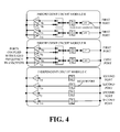
- FIG. 4 is a schematic structural diagram illustrating another radio frequency circuit according to an implementation of the disclosure.
- FIG. 5 is a schematic structural diagram illustrating yet another radio frequency circuit according to an implementation of the disclosure.
- FIG. 6 is a schematic structural diagram illustrating still another radio frequency circuit according to an implementation of the disclosure.
- FIG. 7 is a schematic structural diagram illustrating still another radio frequency circuit according to an implementation of the disclosure.
- FIG. 8 is a schematic structural diagram illustrating still another radio frequency circuit according to an implementation of the disclosure.
- FIG. 9 is a schematic structural diagram illustrating still another radio frequency circuit according to an implementation of the disclosure.
- FIG. 10 is a schematic structural diagram illustrating still another radio frequency circuit according to an implementation of the disclosure.
- FIG. 11 is a schematic structural diagram illustrating an antenna system of an electronic device according to an implementation of the disclosure.
- FIG. 12 is a schematic structural diagram illustrating another antenna system of an electronic device according to an implementation of the disclosure.
- FIG. 13 is a schematic structural diagram illustrating a radio frequency system according to an implementation of the disclosure.
- FIG. 14 is a schematic structural diagram illustrating a wireless communication device according to an implementation of the disclosure.
- FIG. 15 is a schematic diagram illustrating a wireless charging receiver for multiplexing an antenna of a wireless communication device according to an implementation of the disclosure.
- FIG. 16 is a schematic structural diagram illustrating a loop array antenna including four antennas according to an implementation of the disclosure.
- the wireless communication device involved in the implementations of the present disclosure may include terminal devices, base stations, and servers that have wireless communication functions.
- the wireless communication device may include at least one of handheld devices, in-vehicle devices, wearable devices (such as smart bracelets, smart watches, wearable glasses, wireless headsets), wireless charging receivers, computing devices or other processing devices connected to the wireless modem, as well as various forms of user equipments (UE), mobile stations (MS), terminal devices, and the like.
- UE user equipments
- MS mobile stations
- terminal devices and the like.
- the above-mentioned devices are collectively referred to as a wireless communication device.
- SRS transmission via four antennas switching of a mobile phone is a mandatory option for China mobile communications corporation (CMCC) in the China mobile fifth generation (5G) Scale Test Technical White Paper_Terminal, which is optional in the 3rd generation partnership project (3GPP).
- CMCC China mobile communications corporation
- 5G Fifth Generation
- 3GPP 3rd generation partnership project
- Its main purpose is for a base station to determine quality and parameters of four channels via measuring uplink signals of the four antennas of the mobile phone, to perform a beamforming of a downlink massive multi-input multi-output (MIMO) antenna array on the four channels according to a channel reciprocity, and finally to obtain the best data transmission performance for a downlink 4 ⁇ 4 MIMO.
- MIMO downlink massive multi-input multi-output
- implementations of the present disclosure provide a radio frequency architecture based on a simplified 4P8T (four P ports and eight T ports) antenna switch.
- the present switching scheme can reduce the number of series switches in each path (all or part of switches are integrated into the 4P8T switch), thereby reducing link loss and optimizing the overall transmission and reception performance of the terminal.
- P port in the disclosure is the abbreviation of “pole port”, which refers to ports coupled with antennas of the multiway switch.
- T port in the disclosure is the abbreviation of “throw port”, which refers to ports coupled with radio frequency modules of the multiway switch.
- a 4P4T switch refers to a switch that has four P ports coupled with antennas and four T ports coupled with a radio frequency circuit.
- Module herein can refer to circuits and any combination of related components.
- the concept of coupling, full coupling, or other kinds of coupling between the T ports and the P ports of the multiway switch described in the implementations of the disclosure refers to a state in which the T ports are coupled with the P ports through first switch transistors.
- One T port or one P port may be one port of a second switch transistor.
- the first switch transistors are configured to control a unidirectional conduction state between the T ports and the P ports (including a unidirectional conduction state from the T ports to the P ports and a unidirectional conduction state from the P ports to the T ports).
- the first switch transistor can be, for example, a switch array including three metal-oxide-semiconductor (MOS) transistors.
- the first switch transistor is implemented with three MOS transistors, where the three MOS transistors can be in a common source connection, that is, coupled at a common source.
- the second switch transistor is configured to enable a corresponding port (T port or P port) and can be, for example, a MOS transistor.
- the specific configurations of the first switch transistor and the second switch transistor are not limited herein.
- the electronic device can control paths between the T ports and the P ports to switch on through the first switch transistors.
- the electronic device can be provided with a dedicated controller to be coupled with switch transistors of the multiway switch.
- the transmitting a sounding reference signal (SRS) through the four antennas corresponding to the four P ports in turn refers to a process in which the electronic device interacts with a base station based on polling mechanism to determine quality of an uplink channel corresponding to each antenna.
- SRS sounding reference signal
- FIG. 1 is a schematic structural diagram illustrating a multiway switch 10 according to an implementation of the disclosure.
- the multiway switch 10 includes eight T ports and four P ports. Four T ports of the eight T ports are coupled with all of the four P ports (that is, fully-coupled). Two T ports at different frequency bands of the remaining four T ports are coupled with one of the four P ports, and the other two T ports at different frequency bands of the remaining four T ports are coupled with another one of the four P ports.
- the multiway switch 10 is applicable to a wireless communication device.
- the wireless communication device can be an electronic device 100 illustrated in FIG. 1 .
- the electronic device 100 is operable in a dual-frequency dual-transmit mode and includes an antenna system 20 and a radio frequency circuit 30 .
- the antenna system 20 includes four antennas. The four antennas correspond to the four P ports; specifically, the four antennas and the four P ports are in one-to-one correspondence.
- the multiway switch 10 is configured to be coupled with the radio frequency circuit 30 and the antenna system 20 to implement a preset function of the electronic device 100 .
- the preset function is a function of transmitting an SRS through the four antennas corresponding to the four P ports in turn, which can be understood as a four-port SRS function.
- the electronic device may be a mobile phone or other terminal devices supporting the fifth generation new radio (5G NR), such as a customer premise equipment (CPE) or a mobile wireless-fidelity (MIFI).
- 5G NR fifth generation new radio
- CPE customer premise equipment
- MIFI mobile wireless-fidelity
- the dual-frequency dual-transmit mode refers to an operating mode in which the electronic device 100 can support at most dual frequency band-two UL transmit paths or dual frequency band-four DL receive paths.
- the multiway switch 10 includes field-effect transistors (FET). As four T ports of the eight T ports are fully coupled with the four P ports and the other four T ports of the eight T ports are only configured to be coupled with one fixed antenna for receiving, the number of built-in FETs, volume, and cost of the 4P8T switch can be reduced and performance can be improved. Details will be described hereinafter.
- FET field-effect transistors
- the electronic device is operable in the dual-frequency dual-transmit mode
- the number of switches of a radio frequency system of the electronic device can be effectively reduced. That is to say, the number of fully coupled T ports has a great influence on performance of the radio frequency system.
- the electronic device 100 further includes a radio frequency transceiver.
- the radio frequency transceiver is coupled with the radio frequency circuit 30 and constitutes a radio frequency system of the electronic device 100 together with the radio frequency circuit 30 , the multiway switch 10 , and the antenna system 20 .
- the multiway switch 10 is provided, which is applicable to the electronic device 100 .
- the electronic device 100 is operable in the dual-frequency dual-transmit mode and includes the antenna system 20 , the radio frequency circuit 30 , and the multiway switch 10 .
- the antenna system 20 includes the four antennas.
- the multiway switch 10 includes the eight T ports and the four P ports. Four T ports of the eight T ports are fully coupled with the four P ports.
- the multiway switch 10 is configured to be coupled with the radio frequency circuit 30 and the antenna system 20 to implement the preset function of the electronic device 100 , and the preset function is a function of transmitting an SRS through the four antennas corresponding to the four P ports in turn.
- the eight T ports include four first T ports and four second T ports.
- Each of the four first T ports is fully coupled with the four P ports.
- Two of the four second T ports at different frequency bands are coupled with one of the four P ports, and the other two of the four second T ports at different frequency bands are coupled with another one of the four P ports.
- Each of the four P ports is configured to be coupled with a corresponding antenna of the four antennas.
- the four first T ports support a transmission-reception function and the four second T ports support only a reception function.
- the multiway switch 10 since the multiway switch 10 includes the first T ports and the second T ports and the number of the second T ports is not 0, in comparison with a configuration in which all T ports are fully coupled with P ports, for the multiway switch 10 provided herein, the number of switches is reduced. That is, the number of the switches in transmit paths and/or receive paths of the radio frequency system of the electronic device 100 can be reduced, thereby reducing path loss, improving transmit power/sensitivity, data transmission rate in the 5G NR, and uplink and downlink coverage of the mobile phone, and reducing power consumption and cost.
- One of the four transmitter circuits and one of the eight receiver circuits are integrated into one transceiver integrated circuit (can be comprehended as an integrated circuit for transmitting, receiving, and/or processing signals) through a switch, another one of the four transmitter circuits and another one of the eight receiver circuits are integrated into another one transceiver integrated circuit through a switch, yet another one of the four transmitter circuits and yet another one of the eight receiver circuits are integrated into yet another one transceiver integrated circuit through a switch, and still another one of the four transmitter circuits and still another one of the eight receiver circuits are integrated into still another one transceiver integrated circuit through a switch. That is to say, there are four transceiver integrated circuits in total that are distributed to at most four independent circuit modules.
- Each transceiver integrated circuit is coupled with a first port of an independent circuit module to which this transceiver integrated circuit belongs. Since the four transmitter circuits and the four of the eight receiver circuits are integrated into the four transceiver integrated circuits, the remaining four receiver circuits are disposed individually. The remaining four receiver circuits can belong to one independent circuit module or an independent circuit module to which a transceiver integrated circuit belongs. The independent circuit module(s) to which the four receiver circuits belong is not limited herein. In the case that the remaining four receiver circuits belong to one independent circuit module, the remaining four receiver circuits are coupled with four second ports of the independent circuit module (in one-to-one correspondence). In the case that the independent circuit modules to which the four transceiver integrated circuits and the remaining four receiver circuits belong are not limited, the radio frequency circuit 30 can be illustrated in FIGS. 3A, 4, 5, 6, 7, 8, 9, and 10 .
- the matching manner of the above radio frequency circuit 30 and the multiway switch 10 includes but is not limited to the structure of the drawing, and is merely an example herein.
- the multiway switch 10 of the implementation of the disclosure can enable the electronic device 100 to be operable in the dual-frequency dual-transmit mode. It is beneficial to simplifying the RF architecture of the electronic device supporting four-port SRS switching in the 5G NR, reducing the number of switches in transmit paths and receive paths, and reducing path loss, thereby improving transmit power/sensitivity, data transmission rate in the 5G NR, and uplink and downlink coverage of the mobile phone, and reducing power consumption.
- the radio frequency circuit 30 physically includes two independent circuit modules.
- the two independent circuit modules include two first independent circuit modules, where the first independent circuit module is embodied as an independent circuit module A.
- the independent circuit module A includes two first ports and two second ports. Each first port is coupled with one of the four first T ports, and each second port is coupled with one of the four second T ports.
- the independent circuit module A includes two transceiver integrated circuits and two receiver circuits. The two transceiver integrated circuits work at different frequency bands.
- Each transceiver integrated circuit includes one transmitter circuit and one receiver circuit and has a transmit-receive port coupled with one first port of the independent circuit module A.
- Each receiver circuit has a receive port coupled with one second port of the independent circuit module A. Details will be described hereinafter.
- the radio frequency circuit 30 physically includes three independent circuit modules.
- the three independent circuit modules include two first independent circuit modules and one second independent circuit module.
- the first independent circuit module is embodied as an independent circuit module B and the second independent circuit module is embodied as an independent circuit module C.
- the independent circuit module B includes two first ports, and the independent circuit module C includes four second ports. Each first port is coupled with one of the four first T ports, and each second port is coupled with one of the four second T ports.
- the independent circuit module B includes two transceiver integrated circuits. The two transceiver integrated circuits work at different frequency bands.
- Each transceiver integrated circuit includes one transmitter circuit and one receiver circuit and has a transmit-receive port coupled with one first port of the independent circuit module B.
- the independent circuit module C includes four receiver circuits. Each receiver circuit has a receive port coupled with one second port of the independent circuit module C. Details will be described hereinafter.
- the radio frequency circuit 30 physically includes three independent circuit modules.
- the three independent circuit modules include two first independent circuit modules and one second independent circuit module.
- the first independent circuit module is embodied as an independent circuit module D and the second independent circuit module is embodied as an independent circuit module E.
- the independent circuit module D includes two first ports and one second port, and the independent circuit module E includes two second ports. Each first port is coupled with one of the four first T ports, and each second port is coupled with one of the four second T ports.
- the independent circuit module D includes two transceiver integrated circuits and one receiver circuit. The two transceiver integrated circuits work at different frequency bands.
- Each transceiver integrated circuit includes one transmitter circuit and one receiver circuit and has a transmit-receive port coupled with one first port of the independent circuit module D.
- the receiver circuit has a receive port coupled with the second port of the independent circuit module D.
- the independent circuit module E includes two receiver circuits. Each receiver circuit has a receive port coupled with one second port of the independent circuit module E. Details will be described hereinafter.
- the radio frequency circuit 30 physically includes four independent circuit modules.
- the four independent circuit modules include four first independent circuit modules, where the first independent circuit module is embodied as an independent circuit module F.
- the independent circuit module F includes one first port and one second port. Each first port is coupled with one of the four first T ports, and each second port is coupled with one of the four second T ports.
- the independent circuit module F includes one transceiver integrated circuit and one receiver circuit.
- the transceiver integrated circuit includes one transmitter circuit and one receiver circuit and has a transmit-receive port coupled with the first port of the independent circuit module F.
- the receiver circuit module has a receive port coupled with the second port of the independent circuit module F. Details will be described hereinafter.
- the radio frequency circuit 30 physically includes four independent circuit modules.
- the four independent circuit modules include two first independent circuit modules and two second independent circuit modules.
- the first independent circuit module is embodied as an independent circuit module G and the second independent circuit module is embodied as an independent circuit module H.
- the independent circuit module G includes one first port and two second ports and the independent circuit module H includes one first port. Each first port is coupled with one of the four first T ports, and each second port is coupled with one of the four second T ports.
- the independent circuit module G includes one transceiver integrated circuit and two receiver circuits.
- the transceiver integrated circuit includes one transmitter circuit and one receiver circuit and has a transmit-receive port coupled with the first port of the independent circuit module G. Each receiver circuit has a receive port coupled with one second port of the independent circuit module G.
- the independent circuit module H includes one transceiver integrated circuit.
- the transceiver integrated circuit includes one transmitter circuit and one receiver circuit and has a transmit-receive port coupled with the first port of the independent circuit module H. Details will be described hereinafter.
- the radio frequency circuit 30 physically includes five independent circuit modules.
- the five independent circuit modules include one first independent circuit module and four second independent circuit modules.
- the first independent circuit module is embodied as an independent circuit module C and the second independent circuit module is embodied as an independent circuit module H.
- the independent circuit module C includes four second ports, and the independent circuit module H includes one first port. Each first port is coupled with one of the four first T ports, and each second port is coupled with one of the four second T ports.
- the independent circuit module C includes four receiver circuits. Each receiver circuit has a receive port coupled with one second port of the independent circuit module C.
- the independent circuit module H includes one transceiver integrated circuit.
- the transceiver integrated circuit includes one transmitter circuit and one receiver circuit and has a transmit-receive port coupled with the first port of the independent circuit module H. Details will be described hereinafter.
- the radio frequency circuit 30 physically includes six independent circuit modules.
- the six independent circuit modules include two first independent circuit modules and four second independent circuit modules.
- the first independent circuit module is embodied as an independent circuit module E and the second independent circuit module is embodied as an independent circuit module H.
- the independent circuit module E includes two second ports, and the independent circuit module H includes one first port. Each first port is coupled with one of the four first T ports, and each second port is coupled with one of the four second T ports.
- the independent circuit module E includes two receiver circuits. Each receiver circuit has a receive port coupled with one second port of the independent circuit module E.
- the independent circuit module H includes one transceiver integrated circuit.
- the transceiver integrated circuit includes one transmitter circuit and one receiver circuit and has a transmit-receive port coupled with the first port of the independent circuit module H. Details will be described hereinafter.
- the radio frequency circuit 30 physically includes eight independent circuit modules.
- the eight independent circuit modules include four first independent circuit modules and four second independent circuit modules.
- the first independent circuit module is embodied as an independent circuit module H and the second independent circuit module is embodied as an independent circuit module I.
- the independent circuit module H includes one first port, and the independent circuit module I includes one second port. Each first port is coupled with one of the four first T ports, and each second port is coupled with one of the four second T ports.
- the independent circuit module H includes one transceiver integrated circuit.
- the transceiver integrated circuit includes one transmitter circuit and one receiver circuit and has a transmit-receive port coupled with the first port of the independent circuit module H.
- the independent circuit module I includes one receiver circuit.
- the receiver circuit has a receive port coupled with the second port of the independent circuit module I. Details will be described hereinafter.
- the coupling manner between the four first ports and the four first T ports is one-to-one correspondence (one first port coupled with one first T port), and the coupling manner between the four second ports and the four second T ports is one-to-one correspondence.
- the above expression of “each first port is coupled with one of the four first T ports” means that four first ports are coupled in one-to-one correspondence with four first T ports; similarly, the above expression of “each second port is coupled with one of the four second T ports” means that four second ports are coupled in one-to-one correspondence with four second T ports.
- each transceiver integrated circuit is coupled with one first port of an independent circuit module to which this transceiver integrated circuit belongs.
- the two transceiver integrated circuits are coupled with two first ports of the forgoing independent circuit module in one-to-one correspondence.
- Each receiver circuit in the above implementations is coupled with one second port of an independent circuit module to which this receiver circuit belongs.
- the multiple receiver circuits are coupled with second ports of the forgoing independent circuit module in one-to-one correspondence.
- LNA low-noise amplifiers
- the receiver circuits can operate simultaneously, due to their low power and low power consumption, mutual influence can be avoided through design. Therefore, multiple LNAs in multiple receiver circuits at the same frequency band can be disposed in the same circuit module.
- PAs power amplifiers
- the two PAs will affect heat dissipation efficiency when working at the same time.
- the implementations of the present disclosure include four transmitter circuits, two of the four transmitter circuits at the same frequency band cannot be set in the same circuit module. Therefore, when two PAs are disposed in the same circuit module, the two PAs are at different frequency bands. That is to say, two transceiver integrated circuits at the same frequency band cannot be disposed in the same circuit module.
- transceiver integrated circuits can be implemented in various manners.
- the implementations of the disclosure are not particularly restricted.
- Each receiver circuit in the above implementations includes one LNA and one filter.
- the filter has a receive port (a receive port of a receiver circuit) coupled with a second port of an independent circuit module to which this receiver circuit belongs.
- the filter has an output port coupled with a receive port of the LNA.
- the LNA has an output port coupled with a corresponding port of the radio frequency transceiver.
- Each transceiver integrated circuit in the above implementations includes one PA, one LNA, one switch, one filter, and one power coupler.
- the PA has a receive port coupled with a corresponding port of the radio frequency transceiver.
- the LNA has an output port coupled with a corresponding port of the radio frequency transceiver.
- the PA has an output port coupled with a first selection port of the switch.
- the LNA has a receive port coupled with a second selection port of the switch.
- the switch has a common port coupled with one port of the filter.
- the filter has the other one port coupled with a first port of the power coupler.
- the power coupler has a second port (a transmit-receive port of a transceiver integrated circuit) coupled with a first port of an independent circuit module to which this transceiver integrated circuit belongs.
- radio frequency circuit 30 physically includes two independent circuit modules.
- the radio frequency circuit 30 physically includes two independent circuit modules A.
- the independent circuit module A includes two transceiver integrated circuits and two receiver circuits. Each transmission-receiver circuit includes one transmitter circuit and one receiver circuit.
- the two transceiver integrated circuits of the independent circuit module A include a first transceiver integrated circuit and a second transceiver integrated circuit.
- the two receiver circuits of the independent circuit module A include a first receiver circuit and a second receiver circuit.
- the first transceiver integrated circuit includes one LNA, one PA, and one power coupler.
- the LNA is coupled with a “PRX_NY” pin (a fourth receive port at the NY frequency band).
- the PA is coupled with a “TX_CH0_NY” pin (a transmit port of a first transmit path at the NY frequency band).
- the power coupler is coupled with one first port of the independent circuit module A.
- the first port is coupled with one first T port of the multiway switch 10 .
- the second transmission-receiver circuit includes one LNA, one PA, and one power coupler.
- the LNA is coupled with a “PRX_NX” pin (a fourth receive port at the NX frequency band.
- the PA is coupled with a “TX_CH0_NX” pin (a transmit port of a first transmit path at the NX frequency band).
- the power coupler is coupled with the other first port of the independent circuit module A.
- the first port is coupled with another one first T port of the multiway switch 10 .
- the first receiver circuit includes one LNA and one filter.
- the LNA is coupled with a “RX1_NY” pin (a third receive port at the NY frequency band).
- the filter is coupled with one second port of the independent circuit module A.
- the second port is coupled with one second T port of the multiway switch 10 .
- the second receiver circuit includes one LNA and one filter.
- the LNA is coupled with a “RX1_NX” pin (a third receive port at the NX frequency band).
- the filter is coupled with the other second port of the independent circuit module A.
- the second port is coupled with another one second T port of the multiway switch 10 .
- NR BAND NY TRX1 and “NR BAND NY TRX2” represent pins corresponding to two transceiver integrated circuits at the NY frequency band.
- NR BAND NX TRX1 and “NR BAND NX TRX2” represent pins corresponding to two transceiver integrated circuits at the NX frequency band.
- NR BAND NY RX3 and “NR BAND NY TRX4 represent pins corresponding to two receiver circuits at the NY frequency band.
- NR BAND NX RX3 and “NR BAND NX TRX4 represent pins corresponding to two receiver circuits at the NX frequency band.
- the four LNAs of the other one independent circuit module A are respectively coupled with a “RX2_NY” pin (a second receive port at the NY frequency band), a “RX2_NX” pin (a second receive port at the NX frequency band), a “RX3_NY” pin (a first receive port at the NY frequency band) and a “RX3_NX” pin (a first receive port at the NX frequency band) of the radio frequency transceiver.
- the two PAs are respectively coupled with a “TX_CH1_NY” pin (a transmit port of a second transmit path at the NY frequency band) and a “TX_CH1_NX” pin (a transmit port of a second transmit path at the NX frequency band).
- the coupling manners of other circuits and the multiway switch 10 are similar to those of the first independent circuit module, and are not repeated herein.
- the coupling manners of the radio frequency transceiver, the radio frequency circuit 30 , and the multiway switch 10 illustrated in FIGS. 4, 5, 6, 7, 8, 9, and 10 are similar to those of the radio frequency transceiver, the radio frequency circuit 30 , and the multiway switch 10 illustrated in FIG. 3A and FIG. 3B , and are not repeated herein.
- the four antennas include a first antenna, a second antenna, a third antenna, and a fourth antenna. These four antennas are all operable at a fifth generation new radio (5G NR) frequency band.
- 5G NR fifth generation new radio
- the 5G NR frequency band may include, for example, 3.3 GHz to 3.8 GHz and 4.4 GHz to 5 GHz.
- the four antennas include a first antenna, a second antenna, a third antenna, and a fourth antenna.
- the first antenna and the fourth antenna are antennas operable at a long term evolution (LTE) frequency band and a fifth generation new radio (5G NR) frequency band.
- the second antenna and the third antenna are antennas only operable at the 5G NR frequency band.
- the first antenna and fourth antenna are intended to support DL 4 ⁇ 4 MIMO for some frequency bands in LTE on terminals. These two antennas are shared with the 5G NR (hereinafter, “shared antennas” for short).
- the LTE frequency band may include, for example, 1880-1920 MHz and 2496-2690 MHz.
- the antenna system further includes a first combiner and a second combiner.
- the first combiner has a first port configured to be coupled with the first antenna, a second port configured to be coupled with a first receive path in LTE 4 ⁇ 4 multiple-input multiple-output (MIMO) configuration of the electronic device 100 , and a third port configured to be coupled with a corresponding P port of the multiway switch 10 .
- the second combiner has a first port configured to be coupled with the fourth antenna, a second port configured to be coupled with a second receive path in the LTE 4 ⁇ 4 MIMO configuration of the electronic device 100 , and a third port configured to be coupled with a corresponding P port of the multiway switch 10 .
- the LTE 4*4 MIMO is a downlink LTE receive circuit and can be defined as a third receive path. Since the LTE currently has two receive paths, in order to support LTE 4 ⁇ 4 MIMO, the third path and a fourth receive path are added.
- the electronic device 100 will arrange one antenna with better performance for the circuit for PRX (primary receiver), and the antenna will be in a standby state.
- first T ports of the switch having the transmission-reception function can be configured for TX (transmit) and PRX purpose, and thus the antenna can be switched arbitrarily. In this way, there is no need to restrict the coupling between ports of shared antennas.
- the antenna system 20 further includes a first single-pole double-throw (SPDT) switch and a second SPDT switch.
- the first SPDT switch has a first port configured to be coupled with the first antenna, a second port configured to be coupled with a first receive path in LTE 4 ⁇ 4 MIMO configuration of the electronic device 100 , and a third port configured to be coupled with a corresponding P port of the multiway switch 10 .
- the second SPDT switch has a first port configured to be coupled with the fourth antenna, a second port configured to be coupled with a second receive path in the LTE 4 ⁇ 4 MIMO configuration of the electronic device 100 , and a third port configured to be coupled with a corresponding P port of the multiway switch 10 .
- the antenna system and/or the multiway switch described above can be applied or combined into the radio frequency system and the terminal device below.
- the antenna system and/or the multiway switch of the disclosure means “the antenna system”, “the multiway switch”, or “the antenna system and the multiway switch”.
- FIG. 13 is a schematic structural diagram illustrating a radio frequency system according to an implementation of the disclosure.
- the radio frequency system includes an antenna system, a radio frequency circuit, and a multiway switch coupled with the radio frequency circuit and the antenna system.
- the multiway switch includes eight T ports and four P ports.
- the eight T ports includes four first T ports and each of the four first T ports is coupled with all of the four P ports.
- the four first T ports support a transmission-reception function.
- the antenna system includes four antennas corresponding to the four P ports.
- the multiway switch is configured to implement a preset function of transmitting an SRS through the four antennas in turn.
- the eight T ports further include four second T ports. Two of the four second T ports at different frequency bands are coupled with one of the four P ports. The other two of the four second T ports at different frequency bands are coupled with another one of the four P ports. Each of the four P ports is configured to be coupled with a corresponding antenna of the four antennas.
- the four second T ports support only a reception function.
- the four antennas include a first antenna, a second antenna, a third antenna, and a fourth antenna.
- the first antenna and the fourth antenna are antennas operable at an LTE frequency band and a 5G NR frequency band.
- the second antenna and the third antenna are antennas only operable at the 5G NR frequency band.
- the antenna system further includes a first combiner and a second combiner.
- the first combiner has a first port coupled with the first antenna, a second port coupled with a first receive path in LTE 4 ⁇ 4 MIMO configuration of the electronic device, and a third port coupled with a corresponding P port of the multiway switch.
- the second combiner has a first port coupled with the fourth antenna, a second port coupled with a second receive path in the LTE 4 ⁇ 4 MIMO configuration of the electronic device, and a third port coupled with a corresponding P port of the multiway switch.
- the antenna system 20 further includes a first single-pole double-throw (SPDT) switch and a second SPDT switch.
- the first SPDT switch has a first port coupled with the first antenna, a second port coupled with a first receive path in LTE 4 ⁇ 4 multiple-input multiple-output (MIMO) of the electronic device 100 , and a third port coupled with a corresponding P port of the multiway switch.
- the second SPDT switch has a first port coupled with the fourth antenna, a second port coupled with a second receive path in the LTE 4 ⁇ 4 MIMO of the electronic device 100 , and a third port coupled with a corresponding P port of the multiway switch.
- the transmit paths can include one single independent switch (a 4P8T switch) or two independent switches (a SPDT switch and a 4P8T switch), and the receive paths can include one single independent switch (a 4P8T switch) or two independent switches (a SPDT switch and a 4P8T switch). That is to say, by integrating more switch functions of the transmit paths and the receive paths of the radio frequency system into the 4P8T switch, the number of independent switches of the transmit paths and the receive paths can be effectively reduced.
- FIG. 14 is a schematic structural diagram illustrating a wireless communication device according to an implementation of the disclosure.
- the wireless communication device for example can be a terminal device, a base station, and the like and includes an antenna system, a radio frequency transceiver, a radio frequency circuit coupled with the radio frequency transceiver, and the multiway switch described in any of the implementations above.
- the multiway switch includes eight T ports and four P ports.
- the antenna system includes four antennas corresponding to the four P ports.
- the eight T ports include four first T ports and four second T ports. Each of the four first T ports is coupled with all of the four P ports.
- the four first T ports support a transmission-reception function. Two of the four second T ports at different frequency bands are coupled with one of the four P ports. The other two of the four second T ports at different frequency bands are coupled with another one of the four P ports.
- the four second T ports support only a reception function.
- Each of the four P ports is configured to be coupled with a corresponding antenna of the four antennas.
- the multiway switch is coupled with the radio frequency circuit and the antenna system and supports a preset function of transmitting an SRS through the four antennas in turn.
- the four antennas in the antenna system described in the implementations of the disclosure can also be multiplexed by a wireless charging receiver of the electronic device 100 .
- the wireless charging receiver includes a receive antenna and a receive control circuit.
- the receive antenna matches transmit antennas of a wireless charging transmitter (resonates at the same or similar frequency and transfers energy in a wireless manner in the way of radiative resonant magnetic coupling).
- the receive control circuit converts, through a loop array antenna, the energy into a direct current (DC) to output to charge a battery.
- the receive control circuit can dynamically adjust a frequency of the loop array antenna and match the frequency of the loop array antenna with frequencies of the transmit antennas of the wireless charging transmitter to achieve paired charging.
- the receive control circuit interacts with the wireless charging transmitter in real time on a frequency change range to implement an “exclusive encryption” wireless charging mode.
- the receive antenna may be an antenna include at least one of the four antennas (in the case of multiple antennas, the multiple antennas are strobed via switches).
- the receive antenna is a loop array antenna including the four antennas described above.
- the four antennas include antenna 1, antenna 2, antenna 3, and antenna 4.
- Antenna 1 and antenna 4 are operable at both an LTE frequency band and a 5G NR frequency band, while antenna 2 and antenna 3 are only operable at the 5G NR frequency band.
- a port of antenna 1 and a port of antenna 4 are used as ports of the loop array antenna.
- Adjacent antennas are coupled via a gate circuit 170 with an isolation function.
- the gate circuit 170 includes a spacer 171 and a switch 172 , where the spacer 171 is a conductor and the switch 172 is further coupled with a controller.
- the electronic device 100 can conduct the switch 172 of each gate circuit 170 in a wireless charging mode to form a loop array antenna to receive energy.
- the gate circuit 170 can reduce mutual coupling among the multiple antennas of the electronic device 100 in a normal communication mode, improve isolation among the multiple antennas, and optimize performance of the antennas.
- the multiple antennas can be coupled in series to form the loop array antenna through the switches 172 , so as to better match the transmit antennas to transfer energy.
- antenna 1 and antenna 4 have capabilities stronger than that of antenna 2 and antenna 3, the loop array antenna thus arranged can reduce energy loss in transmission as much as possible.
Landscapes
- Engineering & Computer Science (AREA)
- Computer Networks & Wireless Communication (AREA)
- Signal Processing (AREA)
- Power Engineering (AREA)
- Transceivers (AREA)
- Waveguide Switches, Polarizers, And Phase Shifters (AREA)
Abstract
Description
Claims (19)
Applications Claiming Priority (2)
| Application Number | Priority Date | Filing Date | Title |
|---|---|---|---|
| CN2018102207118 | 2018-03-16 | ||
| CN201810220711.8A CN108512556B (en) | 2018-03-16 | 2018-03-16 | Multi-way selector switch, radio frequency system and wireless communication equipment |
Publications (2)
| Publication Number | Publication Date |
|---|---|
| US20190288736A1 US20190288736A1 (en) | 2019-09-19 |
| US10554244B2 true US10554244B2 (en) | 2020-02-04 |
Family
ID=63375816
Family Applications (1)
| Application Number | Title | Priority Date | Filing Date |
|---|---|---|---|
| US16/173,501 Active US10554244B2 (en) | 2018-03-16 | 2018-10-29 | Multiway switch, radio frequency system, and wireless communication device |
Country Status (7)
| Country | Link |
|---|---|
| US (1) | US10554244B2 (en) |
| EP (1) | EP3540957B1 (en) |
| JP (1) | JP7065961B2 (en) |
| KR (1) | KR102318243B1 (en) |
| CN (1) | CN108512556B (en) |
| AU (1) | AU2018412818B2 (en) |
| WO (1) | WO2019174233A1 (en) |
Cited By (6)
| Publication number | Priority date | Publication date | Assignee | Title |
|---|---|---|---|---|
| US20190288719A1 (en) * | 2018-03-16 | 2019-09-19 | Guangdong Oppo Mobile Telecommunications Corp., Ltd. | Multiway Switch, Radio Frequency System, and Wireless Communication Device |
| US20190288735A1 (en) * | 2018-03-16 | 2019-09-19 | Guangdong Oppo Mobile Telecommunications Corp., Ltd | Multiway Switch, Radio Frequency System, and Wireless Communication Device |
| US10727584B2 (en) | 2018-03-16 | 2020-07-28 | Guangdong Oppo Mobile Telecommunications Corp., Ltd. | Multiway switch for transmitting sounding reference signal successively through a set of antennas |
| US11445402B1 (en) | 2020-10-30 | 2022-09-13 | Sprint Communications Company L.P. | Wireless data service using dynamic data rates based on serving radio bands and historical data rates |
| US12381592B2 (en) | 2021-07-07 | 2025-08-05 | Samsung Electronics Co., Ltd. | Wireless communication device including radio frequency integrated circuit and method of controlling the same |
| US12562774B2 (en) * | 2021-06-09 | 2026-02-24 | Murata Manufacturing Co., Ltd. | Radio frequency circuit, communication device, and control method |
Families Citing this family (16)
| Publication number | Priority date | Publication date | Assignee | Title |
|---|---|---|---|---|
| CN108494461B (en) | 2018-03-16 | 2020-06-16 | Oppo广东移动通信有限公司 | Wireless communication device |
| CN108462498B (en) | 2018-03-16 | 2020-05-05 | Oppo广东移动通信有限公司 | Multiplexer switches, radio frequency systems and wireless communication equipment |
| CN108199730B (en) | 2018-03-16 | 2020-11-06 | Oppo广东移动通信有限公司 | Multiplexer switches, radio frequency systems, and wireless communication equipment |
| CN108599779B (en) * | 2018-03-16 | 2020-03-10 | Oppo广东移动通信有限公司 | Wireless communication device with multiple-way selector switch |
| CN108512567B (en) * | 2018-03-16 | 2020-06-23 | Oppo广东移动通信有限公司 | Multiplexer switches, radio frequency systems and wireless communication equipment |
| CN108199729B (en) | 2018-03-16 | 2020-09-04 | Oppo广东移动通信有限公司 | Multi-way selector switch, radio frequency system and wireless communication equipment |
| CN108462506B (en) | 2018-03-16 | 2020-06-23 | Oppo广东移动通信有限公司 | Multiplexer switches, radio frequency systems and wireless communication equipment |
| CN108512556B (en) * | 2018-03-16 | 2020-06-16 | Oppo广东移动通信有限公司 | Multi-way selector switch, radio frequency system and wireless communication equipment |
| CN108390693A (en) | 2018-03-16 | 2018-08-10 | 广东欧珀移动通信有限公司 | Multidiameter option switch and Related product |
| TWI761669B (en) * | 2019-03-29 | 2022-04-21 | 緯創資通股份有限公司 | Mobile device and antenna structure |
| US10756786B1 (en) * | 2019-04-30 | 2020-08-25 | Corning Research & Development Corporation | Systems and methods for providing isolation for antennas in a wireless communication system |
| CN111525933B (en) * | 2020-04-30 | 2021-12-17 | 维沃移动通信有限公司 | Radio frequency circuit and electronic equipment |
| CN112468178B (en) * | 2020-11-27 | 2022-08-09 | Oppo广东移动通信有限公司 | Radio frequency system, antenna switching method and customer premises equipment |
| CN213661598U (en) * | 2020-12-02 | 2021-07-09 | Oppo广东移动通信有限公司 | Radio frequency L-PA Mid device, radio frequency transceiving system and communication equipment |
| CN114824791B (en) | 2022-05-31 | 2025-09-23 | 立讯精密工业股份有限公司 | wireless headphones |
| CN117092133B (en) * | 2023-10-16 | 2024-01-09 | 成都市汇智讯新能源科技有限公司 | A detection system and detection method based on energy storage panels |
Citations (32)
| Publication number | Priority date | Publication date | Assignee | Title |
|---|---|---|---|---|
| US6229486B1 (en) | 1998-09-10 | 2001-05-08 | David James Krile | Subscriber based smart antenna |
| CN101154978A (en) | 2006-09-29 | 2008-04-02 | 宣德科技股份有限公司 | Wireless communication receiver and receiving method thereof |
| CN101242213A (en) | 2007-11-28 | 2008-08-13 | 中兴通讯股份有限公司 | A device for transmitting and receiving selection switch and antenna selection switch |
| US20090054093A1 (en) | 2007-08-15 | 2009-02-26 | Qualcomm Incorporated | Antenna switching and uplink sounding channel measurement |
| US7633357B2 (en) * | 2004-03-24 | 2009-12-15 | Mitsubishi Electric Corporation | SPST switch, SPDT switch and MPMT switch |
| CN101867402A (en) | 2010-05-04 | 2010-10-20 | 西安交通大学 | A MIMO system with adaptive antenna selection and its application method |
| CN202103661U (en) | 2011-07-15 | 2012-01-04 | 惠州市正源微电子有限公司 | Multi-mode multi-frequency handset radio frequency front module |
| WO2012026601A1 (en) | 2010-08-27 | 2012-03-01 | 京セラ株式会社 | Wireless base station and communications control method |
| US20130308554A1 (en) | 2012-05-21 | 2013-11-21 | Qualcomm Incorporated | Systems, apparatus, and methods for antenna selection |
| CN103905104A (en) | 2012-12-28 | 2014-07-02 | 中兴通讯股份有限公司 | Multi-antenna sending method based on sounding reference signal, terminal, and base station |
| US20140227982A1 (en) | 2013-02-08 | 2014-08-14 | Rf Micro Devices, Inc. | Front end circuitry for carrier aggregation configurations |
| WO2015131020A1 (en) | 2014-02-27 | 2015-09-03 | Battelle Memorial Institute | System and method for reconfiguring rf signals in a multi-input receiver |
| CN105245295A (en) | 2015-10-10 | 2016-01-13 | 广东欧珀移动通信有限公司 | A multi-antenna radio frequency test device |
| CN105281735A (en) | 2014-06-16 | 2016-01-27 | 英飞凌科技股份有限公司 | Matrix switch |
| CN105634569A (en) | 2015-12-31 | 2016-06-01 | 宇龙计算机通信科技(深圳)有限公司 | Control circuit and terminal achieving carrier aggregation and WIFI double-frequency MIMO |
| CN106559277A (en) | 2015-09-25 | 2017-04-05 | 中兴通讯股份有限公司 | The sending method and device of detection reference signal, signaling configuration method and device |
| CN106685621A (en) | 2015-11-06 | 2017-05-17 | 中兴通讯股份有限公司 | SRS processing method and device |
| US20170149134A1 (en) | 2015-11-23 | 2017-05-25 | Huawei Technologies Co., Ltd. | Sparse Phase-Mode Planar Feed For Circular Arrays |
| CN106788577A (en) | 2017-01-20 | 2017-05-31 | 深圳市金立通信设备有限公司 | A kind of multi-line antenna change-over switch |
| US20170195004A1 (en) | 2016-01-06 | 2017-07-06 | Le Holdings (Beijing) Co., Ltd. | Antenna apparatus applied to mobile terminal and mobile terminal |
| US9831940B2 (en) * | 2015-12-01 | 2017-11-28 | Hughes Network Systems, Llc | Gain/flatness enhancement for RF switch matrix |
| US20170373368A1 (en) * | 2016-06-22 | 2017-12-28 | Skyworks Solutions, Inc. | Electromagnetic coupler arrangements for multi-frequency power detection, and devices including same |
| US20180152955A1 (en) * | 2016-11-30 | 2018-05-31 | Samsung Electronics Co., Ltd. | Method and electronic device for performing data communication using a frequency band shared among different radio access technologies |
| CN108199729A (en) | 2018-03-16 | 2018-06-22 | 广东欧珀移动通信有限公司 | Multidiameter option switch and wireless telecom equipment |
| CN108199727A (en) | 2018-03-16 | 2018-06-22 | 广东欧珀移动通信有限公司 | Multidiameter option switch and Related product |
| US20180205413A1 (en) * | 2017-01-17 | 2018-07-19 | Qualcomm Incorporated | Techniques for low-loss multi-band multiplexing |
| CN108390693A (en) | 2018-03-16 | 2018-08-10 | 广东欧珀移动通信有限公司 | Multidiameter option switch and Related product |
| CN108462506A (en) | 2018-03-16 | 2018-08-28 | 广东欧珀移动通信有限公司 | Multidiameter option switch and Related product |
| CN108462497A (en) | 2018-03-16 | 2018-08-28 | 广东欧珀移动通信有限公司 | Multidiameter option switch and Related product |
| CN108494461A (en) | 2018-03-16 | 2018-09-04 | 广东欧珀移动通信有限公司 | Multidiameter option switch, radio frequency system and wireless telecom equipment |
| CN108494413A (en) | 2018-03-16 | 2018-09-04 | 广东欧珀移动通信有限公司 | Multidiameter option switch and Related product |
| CN108599777A (en) | 2018-03-16 | 2018-09-28 | 广东欧珀移动通信有限公司 | Multidiameter option switch and Related product |
Family Cites Families (4)
| Publication number | Priority date | Publication date | Assignee | Title |
|---|---|---|---|---|
| FR2762948B1 (en) * | 1997-05-02 | 1999-07-23 | Alsthom Cge Alcatel | NETWORK OF SWITCHES |
| US20130308562A1 (en) * | 2012-05-21 | 2013-11-21 | Qualcomm Incorporated | Antenna selection devices, methods, & systems |
| US20140169243A1 (en) * | 2012-12-18 | 2014-06-19 | Rf Micro Devices, Inc. | Mobile communication circuitry for three or more antennas |
| CN108512556B (en) * | 2018-03-16 | 2020-06-16 | Oppo广东移动通信有限公司 | Multi-way selector switch, radio frequency system and wireless communication equipment |
-
2018
- 2018-03-16 CN CN201810220711.8A patent/CN108512556B/en not_active Expired - Fee Related
- 2018-10-19 KR KR1020207015013A patent/KR102318243B1/en not_active Expired - Fee Related
- 2018-10-19 AU AU2018412818A patent/AU2018412818B2/en not_active Ceased
- 2018-10-19 WO PCT/CN2018/111028 patent/WO2019174233A1/en not_active Ceased
- 2018-10-19 JP JP2020529145A patent/JP7065961B2/en active Active
- 2018-10-29 US US16/173,501 patent/US10554244B2/en active Active
- 2018-10-31 EP EP18203601.2A patent/EP3540957B1/en active Active
Patent Citations (32)
| Publication number | Priority date | Publication date | Assignee | Title |
|---|---|---|---|---|
| US6229486B1 (en) | 1998-09-10 | 2001-05-08 | David James Krile | Subscriber based smart antenna |
| US7633357B2 (en) * | 2004-03-24 | 2009-12-15 | Mitsubishi Electric Corporation | SPST switch, SPDT switch and MPMT switch |
| CN101154978A (en) | 2006-09-29 | 2008-04-02 | 宣德科技股份有限公司 | Wireless communication receiver and receiving method thereof |
| US20090054093A1 (en) | 2007-08-15 | 2009-02-26 | Qualcomm Incorporated | Antenna switching and uplink sounding channel measurement |
| CN101242213A (en) | 2007-11-28 | 2008-08-13 | 中兴通讯股份有限公司 | A device for transmitting and receiving selection switch and antenna selection switch |
| CN101867402A (en) | 2010-05-04 | 2010-10-20 | 西安交通大学 | A MIMO system with adaptive antenna selection and its application method |
| WO2012026601A1 (en) | 2010-08-27 | 2012-03-01 | 京セラ株式会社 | Wireless base station and communications control method |
| CN202103661U (en) | 2011-07-15 | 2012-01-04 | 惠州市正源微电子有限公司 | Multi-mode multi-frequency handset radio frequency front module |
| US20130308554A1 (en) | 2012-05-21 | 2013-11-21 | Qualcomm Incorporated | Systems, apparatus, and methods for antenna selection |
| CN103905104A (en) | 2012-12-28 | 2014-07-02 | 中兴通讯股份有限公司 | Multi-antenna sending method based on sounding reference signal, terminal, and base station |
| US20140227982A1 (en) | 2013-02-08 | 2014-08-14 | Rf Micro Devices, Inc. | Front end circuitry for carrier aggregation configurations |
| WO2015131020A1 (en) | 2014-02-27 | 2015-09-03 | Battelle Memorial Institute | System and method for reconfiguring rf signals in a multi-input receiver |
| CN105281735A (en) | 2014-06-16 | 2016-01-27 | 英飞凌科技股份有限公司 | Matrix switch |
| CN106559277A (en) | 2015-09-25 | 2017-04-05 | 中兴通讯股份有限公司 | The sending method and device of detection reference signal, signaling configuration method and device |
| CN105245295A (en) | 2015-10-10 | 2016-01-13 | 广东欧珀移动通信有限公司 | A multi-antenna radio frequency test device |
| CN106685621A (en) | 2015-11-06 | 2017-05-17 | 中兴通讯股份有限公司 | SRS processing method and device |
| US20170149134A1 (en) | 2015-11-23 | 2017-05-25 | Huawei Technologies Co., Ltd. | Sparse Phase-Mode Planar Feed For Circular Arrays |
| US9831940B2 (en) * | 2015-12-01 | 2017-11-28 | Hughes Network Systems, Llc | Gain/flatness enhancement for RF switch matrix |
| CN105634569A (en) | 2015-12-31 | 2016-06-01 | 宇龙计算机通信科技(深圳)有限公司 | Control circuit and terminal achieving carrier aggregation and WIFI double-frequency MIMO |
| US20170195004A1 (en) | 2016-01-06 | 2017-07-06 | Le Holdings (Beijing) Co., Ltd. | Antenna apparatus applied to mobile terminal and mobile terminal |
| US20170373368A1 (en) * | 2016-06-22 | 2017-12-28 | Skyworks Solutions, Inc. | Electromagnetic coupler arrangements for multi-frequency power detection, and devices including same |
| US20180152955A1 (en) * | 2016-11-30 | 2018-05-31 | Samsung Electronics Co., Ltd. | Method and electronic device for performing data communication using a frequency band shared among different radio access technologies |
| US20180205413A1 (en) * | 2017-01-17 | 2018-07-19 | Qualcomm Incorporated | Techniques for low-loss multi-band multiplexing |
| CN106788577A (en) | 2017-01-20 | 2017-05-31 | 深圳市金立通信设备有限公司 | A kind of multi-line antenna change-over switch |
| CN108199727A (en) | 2018-03-16 | 2018-06-22 | 广东欧珀移动通信有限公司 | Multidiameter option switch and Related product |
| CN108199729A (en) | 2018-03-16 | 2018-06-22 | 广东欧珀移动通信有限公司 | Multidiameter option switch and wireless telecom equipment |
| CN108390693A (en) | 2018-03-16 | 2018-08-10 | 广东欧珀移动通信有限公司 | Multidiameter option switch and Related product |
| CN108462506A (en) | 2018-03-16 | 2018-08-28 | 广东欧珀移动通信有限公司 | Multidiameter option switch and Related product |
| CN108462497A (en) | 2018-03-16 | 2018-08-28 | 广东欧珀移动通信有限公司 | Multidiameter option switch and Related product |
| CN108494461A (en) | 2018-03-16 | 2018-09-04 | 广东欧珀移动通信有限公司 | Multidiameter option switch, radio frequency system and wireless telecom equipment |
| CN108494413A (en) | 2018-03-16 | 2018-09-04 | 广东欧珀移动通信有限公司 | Multidiameter option switch and Related product |
| CN108599777A (en) | 2018-03-16 | 2018-09-28 | 广东欧珀移动通信有限公司 | Multidiameter option switch and Related product |
Non-Patent Citations (5)
| Title |
|---|
| Extended European search report issued in corresponding European application No. 18203601.2 dated May 28, 2019. |
| Gao Xiang et al: "Multi-Switch for Antenna Selection in Massive MIMO" 2015 IEEE Global Communications Conference (GLOBECOM), IEEE, Dec. 6, 2015 (Dec. 6, 2015), pp. 1-6, XPQ32872922, DOI: 10.1109/GLOCOM.2014.7417765; abstract; Sections I, III.B, III.C; figures 1, 2, 5, 6. |
| International search report issued in corresponding international application No. PCT/CN2018/112763 dated Jan. 30, 2019. |
| International search report issued in corresponding international application No. PCT/CN2018111028 dated Jan. 3, 2019. |
| Lemieux G et al: "Generating Highly-Routable Sparse Crossbars for PLDS" FPGA'00. ACM/SIGDA International Symposium on Field Programmable Gate Arrays. Monterey, CA, Feb. 9-11, 20; [ACM/SIGDA International Symposium on Field Programmable Gate Arrays], New York, NY: ACM, US, vol. : Conf. 8, Jan. 1, 2000 (Jan. 1, 2000), pp. 155-164, XP008O6O160, DOI: 10.1145/329166.329199; ISBN: 978-1-58113-193-2; Section 2; figure 1. |
Cited By (9)
| Publication number | Priority date | Publication date | Assignee | Title |
|---|---|---|---|---|
| US20190288719A1 (en) * | 2018-03-16 | 2019-09-19 | Guangdong Oppo Mobile Telecommunications Corp., Ltd. | Multiway Switch, Radio Frequency System, and Wireless Communication Device |
| US20190288735A1 (en) * | 2018-03-16 | 2019-09-19 | Guangdong Oppo Mobile Telecommunications Corp., Ltd | Multiway Switch, Radio Frequency System, and Wireless Communication Device |
| US10727584B2 (en) | 2018-03-16 | 2020-07-28 | Guangdong Oppo Mobile Telecommunications Corp., Ltd. | Multiway switch for transmitting sounding reference signal successively through a set of antennas |
| US10727877B2 (en) * | 2018-03-16 | 2020-07-28 | Guangdong Oppo Mobile Telecommunications Corp., Ltd. | Multiway switch, radio frequency system, and wireless communication device |
| US10749562B2 (en) * | 2018-03-16 | 2020-08-18 | Guangdong Oppo Mobile Telecommunications Corp., Ltd. | Multiway switch, radio frequency system, and wireless communication device |
| US11445402B1 (en) | 2020-10-30 | 2022-09-13 | Sprint Communications Company L.P. | Wireless data service using dynamic data rates based on serving radio bands and historical data rates |
| US11792679B2 (en) | 2020-10-30 | 2023-10-17 | T-Mobile Innovations Llc | Wireless data service using dynamic data rates based on serving radio bands and historical data rates |
| US12562774B2 (en) * | 2021-06-09 | 2026-02-24 | Murata Manufacturing Co., Ltd. | Radio frequency circuit, communication device, and control method |
| US12381592B2 (en) | 2021-07-07 | 2025-08-05 | Samsung Electronics Co., Ltd. | Wireless communication device including radio frequency integrated circuit and method of controlling the same |
Also Published As
| Publication number | Publication date |
|---|---|
| KR20200074990A (en) | 2020-06-25 |
| EP3540957B1 (en) | 2020-08-05 |
| WO2019174233A1 (en) | 2019-09-19 |
| JP2021505054A (en) | 2021-02-15 |
| US20190288736A1 (en) | 2019-09-19 |
| AU2018412818A1 (en) | 2020-06-11 |
| AU2018412818B2 (en) | 2021-03-25 |
| JP7065961B2 (en) | 2022-05-12 |
| EP3540957A1 (en) | 2019-09-18 |
| CN108512556B (en) | 2020-06-16 |
| CN108512556A (en) | 2018-09-07 |
| KR102318243B1 (en) | 2021-10-28 |
Similar Documents
| Publication | Publication Date | Title |
|---|---|---|
| US10554244B2 (en) | Multiway switch, radio frequency system, and wireless communication device | |
| US10560130B2 (en) | Multiway switch, radio frequency system, and wireless communication device | |
| US10727877B2 (en) | Multiway switch, radio frequency system, and wireless communication device | |
| US10454508B2 (en) | Multiway switch, radio frequency system, and wireless communication device | |
| AU2018413669B2 (en) | Multiway switch, radio frequency system, and wireless communication device | |
| US10567029B2 (en) | Multiway switch, radio frequency system, and electronic device | |
| US10567027B2 (en) | Multiway switch, radio frequency system, and wireless communication device | |
| US10727584B2 (en) | Multiway switch for transmitting sounding reference signal successively through a set of antennas | |
| US10355738B1 (en) | Multiway switch, radio frequency system, and wireless communication device | |
| US10505578B2 (en) | Multiway switch, radio frequency system, and electronic device | |
| US10615838B2 (en) | Multiway switch, radio frequency system, and electronic device | |
| US10454550B2 (en) | Multiway switch, radio frequency system, and wireless communication device | |
| US10567028B2 (en) | Multiway switch, radio frequency system, and wireless communication device |
Legal Events
| Date | Code | Title | Description |
|---|---|---|---|
| FEPP | Fee payment procedure |
Free format text: ENTITY STATUS SET TO UNDISCOUNTED (ORIGINAL EVENT CODE: BIG.); ENTITY STATUS OF PATENT OWNER: LARGE ENTITY |
|
| AS | Assignment |
Owner name: GUANGDONG OPPO MOBILE TELECOMMUNICATIONS CORP., LT Free format text: ASSIGNMENT OF ASSIGNORS INTEREST;ASSIGNOR:BAI, JIAN;REEL/FRAME:047548/0907 Effective date: 20180706 Owner name: GUANGDONG OPPO MOBILE TELECOMMUNICATIONS CORP., LTD., CHINA Free format text: ASSIGNMENT OF ASSIGNORS INTEREST;ASSIGNOR:BAI, JIAN;REEL/FRAME:047548/0907 Effective date: 20180706 |
|
| STPP | Information on status: patent application and granting procedure in general |
Free format text: PUBLICATIONS -- ISSUE FEE PAYMENT VERIFIED |
|
| STPP | Information on status: patent application and granting procedure in general |
Free format text: NOTICE OF ALLOWANCE MAILED -- APPLICATION RECEIVED IN OFFICE OF PUBLICATIONS |
|
| STPP | Information on status: patent application and granting procedure in general |
Free format text: PUBLICATIONS -- ISSUE FEE PAYMENT VERIFIED |
|
| STCF | Information on status: patent grant |
Free format text: PATENTED CASE |
|
| MAFP | Maintenance fee payment |
Free format text: PAYMENT OF MAINTENANCE FEE, 4TH YEAR, LARGE ENTITY (ORIGINAL EVENT CODE: M1551); ENTITY STATUS OF PATENT OWNER: LARGE ENTITY Year of fee payment: 4 |
|
| AS | Assignment |
Owner name: NOKIA TECHNOLOGIES OY, FINLAND Free format text: ASSIGNMENT OF ASSIGNORS INTEREST;ASSIGNOR:GUANGDONG OPPO MOBILE TELECOMMUNICATIONS CORP., LTD.;REEL/FRAME:071711/0153 Effective date: 20250321 |