US1054834A - Attachment for bath-tubs. - Google Patents
Attachment for bath-tubs. Download PDFInfo
- Publication number
- US1054834A US1054834A US69555312A US1912695553A US1054834A US 1054834 A US1054834 A US 1054834A US 69555312 A US69555312 A US 69555312A US 1912695553 A US1912695553 A US 1912695553A US 1054834 A US1054834 A US 1054834A
- Authority
- US
- United States
- Prior art keywords
- bath
- tubs
- attachment
- tongs
- lazy tongs
- Prior art date
- Legal status (The legal status is an assumption and is not a legal conclusion. Google has not performed a legal analysis and makes no representation as to the accuracy of the status listed.)
- Expired - Lifetime
Links
- 238000010276 construction Methods 0.000 description 5
- 239000007921 spray Substances 0.000 description 5
- 241001274197 Scatophagus argus Species 0.000 description 1
- 238000003287 bathing Methods 0.000 description 1
- 230000008878 coupling Effects 0.000 description 1
- 238000010168 coupling process Methods 0.000 description 1
- 238000005859 coupling reaction Methods 0.000 description 1
- 210000002445 nipple Anatomy 0.000 description 1
- 239000000344 soap Substances 0.000 description 1
Images
Classifications
-
- E—FIXED CONSTRUCTIONS
- E03—WATER SUPPLY; SEWERAGE
- E03C—DOMESTIC PLUMBING INSTALLATIONS FOR FRESH WATER OR WASTE WATER; SINKS
- E03C1/00—Domestic plumbing installations for fresh water or waste water; Sinks
- E03C1/02—Plumbing installations for fresh water
- E03C1/06—Devices for suspending or supporting the supply pipe or supply hose of a shower-bath
Definitions
- My invent-ion relates to attachments for bath-tubs, and it consists in. the constructions, combinations and arrangements herein described and claimed.
- the object of my invention is to provide an improved attachment for bath-tubs comprising a portable shower bath, lavatory. and sitz bath in compact. form for convenient use in transportation, and adapted to supply all the conveniences and luxuries of a complete modern bath room to tourists and to occupants of flats or other contracted quarters.
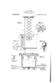
- FIG. 1 is a fragmentary longitudinal section through the spigot end of a bath-tub, illustrating one embodiment of my invention applied thereto and adjusted to constitute a shower bath
- Fig. 2 is a transverse section of a bath-tub, showing my invention applied thereto for providing a lavatory at convenient height for use
- Fig. 3 is an enlarged, detail View, illustrating a preferred hose connection to the annular spray device and the support for a soap dish thereon
- Fig. 4 is an enlarged fragmentary view of the pivotal connection between two adjacent; legs of the lazy tongs constituting my adjustable member
- Fig. 5 is an end View of the construction shown in Fig. 4, with the pivotallyconnected folded in their closed .posi tion
- Fig. 6 is a fragmentary elevation of a modificatnm.
- the brackets 1 are provided with pins 4 for slidably engaging the slotted lower legs of lazy tongs 5, and with vertical slots 6 intermediate of said pins for slidably engaging the lowest pivot bolts 7 of said lazy tongs; said bolts 'T'bcing provided with heads 8 engaging the rear faces of. the brackets l and with wing nuts 1) for securely clamping the lazy tongs in their several adjusted positions.
- hollow annular seat 10 is provided with pins 11 slidably engaging slots in the upper legs of said lazy tongs for interchangeably supporting various bathing vessels, such as a'lavatory or a sitz bath, at different desired heights for convenient use.
- Fig. 2 shows a lavatory 12 extending through the annular seat 10 and Supported in convenient position thereon at any'desired height within a bath-tub by its curled rim 13; a sitz bath 14 similarly supported on the anular seat 10 being indicated by broken lines.
- the hollow annular sea-t 10 is pro-. 'VltlPCl with a series of perforations 16 to constitute a spray device, and IS connected to the bath-tub spigot 15 by a flexible hose 17; said connection being conveniently made by a coupling member 18 swiveledaon the end of the hose 1'? for threadingly engaging a nipple 19. extending from the hollow annular spray device Figs.
- FIGS. 4 and 5 illustrate a construction, in which the pivoted legs of the lazy tongs are provided with raised ends 20 formed with ribs 21 and recesses 9.2 for frictionally resisting shifting of the lazy tongs and yieldingly locking said pivoted legs together in the closed or contracted position of said' tongs.
- Fig. 6 illustrates a modified construction, in which a link 23 ispivoted on the bolt 24 of the lazy tongs and provided with slots 25 adapted to receive an upper bolt 26 of the,
- An attachment for bath-tubs comprising an adjustable member, means for detachably supporting said memberon a bathtub, a hollow annular scat carried by said mci'nber for interchangeably supporting a lavatory or sitz bath at-different desired heights, said hollow seat being perforated neeting said spray device with the usual hath-tub nozzle, and means for locking said member in its several adjusted positions.
- An attachment for bath-tubs comprisinglazy tongs, having their terminal legs provided with slots brackets vfor detachabh supporting said tongs on a bath-tub and provided with pins slidably engaging the lower slotted legs of said tongs said brackets being provided with vertical slots medially of said pins, pivot bolts on said laz tongs extending through such bracket slots for clampingly locking said lazy tongs in their l to constitute a spray device, means for eon- 5 l
Landscapes
- Health & Medical Sciences (AREA)
- Life Sciences & Earth Sciences (AREA)
- Engineering & Computer Science (AREA)
- Hydrology & Water Resources (AREA)
- Public Health (AREA)
- Water Supply & Treatment (AREA)
- Devices For Medical Bathing And Washing (AREA)
Description
S. FISHER.-
ATTACHMENT FOR BATH TUBS. APPLIGATIONFILED MAY 6-, 1012 Patented Mar. 4, 1913.
SAMUEL J. FISHER, OF ASHEVILLE, NORTH CAROLINA;
ATTACHMENT FOR BATH-TUBS.
Specification of Letters Patent.
Patented Mar. 4, 1913.
Application filed May 6, 1912. Serial No. 695,553. 4
. To all whom, it may concern:
Be it known that. I, SAMUEL J. FISHER, a subject of'the King of England, residing at Asheville, in the county of Buncombe and State of North Carolina, have invented certain new and useful Improvements in Attachments for Bath-Tubs; and'I do hereby declare the following to be a full, clear, and
exact description of the invention, such as will enable others skilled in the art to which it appertains to make and use the same.
My invent-ion relates to attachments for bath-tubs, and it consists in. the constructions, combinations and arrangements herein described and claimed.
The object of my invention is to provide an improved attachment for bath-tubs comprising a portable shower bath, lavatory. and sitz bath in compact. form for convenient use in transportation, and adapted to supply all the conveniences and luxuries of a complete modern bath room to tourists and to occupants of flats or other contracted quarters.
In the accompanying drawings forming a partof the application, and in which similar referencesym'bols indicate corresponding parts inthe several views :F igure 1 is a fragmentary longitudinal section through the spigot end of a bath-tub, illustrating one embodiment of my invention applied thereto and adjusted to constitute a shower bath; Fig. 2 is a transverse section of a bath-tub, showing my invention applied thereto for providing a lavatory at convenient height for use; Fig. 3 is an enlarged, detail View, illustrating a preferred hose connection to the annular spray device and the support for a soap dish thereon; Fig. 4 is an enlarged fragmentary view of the pivotal connection between two adjacent; legs of the lazy tongs constituting my adjustable member; Fig. 5 is an end View of the construction shown in Fig. 4, with the pivotallyconnected folded in their closed .posi tion; and Fig. 6 is a fragmentary elevation of a modificatnm.
Referring to the drawings, 1 indicates brackets slidab'ly mounted on the rim of a bath-tub 2, and provided with set screws .3 for rigidly securing thorn in place if desired; The brackets 1 are provided with pins 4 for slidably engaging the slotted lower legs of lazy tongs 5, and with vertical slots 6 intermediate of said pins for slidably engaging the lowest pivot bolts 7 of said lazy tongs; said bolts 'T'bcing provided with heads 8 engaging the rear faces of. the brackets l and with wing nuts 1) for securely clamping the lazy tongs in their several adjusted positions. hollow annular seat 10 is provided with pins 11 slidably engaging slots in the upper legs of said lazy tongs for interchangeably supporting various bathing vessels, such as a'lavatory or a sitz bath, at different desired heights for convenient use.
Fig. 2 shows a lavatory 12 extending through the annular seat 10 and Supported in convenient position thereon at any'desired height within a bath-tub by its curled rim 13; a sitz bath 14 similarly supported on the anular seat 10 being indicated by broken lines. The hollow annular sea-t 10is pro-. 'VltlPCl with a series of perforations 16 to constitute a spray device, and IS connected to the bath-tub spigot 15 by a flexible hose 17; said connection being conveniently made by a coupling member 18 swiveledaon the end of the hose 1'? for threadingly engaging a nipple 19. extending from the hollow annular spray device Figs. 4 and 5 illustrate a construction, in which the pivoted legs of the lazy tongs are provided with raised ends 20 formed with ribs 21 and recesses 9.2 for frictionally resisting shifting of the lazy tongs and yieldingly locking said pivoted legs together in the closed or contracted position of said' tongs.
Fig. 6 illustrates a modified construction, in which a link 23 ispivoted on the bolt 24 of the lazy tongs and provided with slots 25 adapted to receive an upper bolt 26 of the,
lazy tongs, said slots. being formed with recessed portions 27 for lockingly enga ing said bolt 26. The lower legs of the-lazy tongs are shown provided with projecting stops 2% for firmly supporting the lazy tongs in collapsed or closed position.
I have illustrated and describcdpreferred and satisfaetoi'y constructions, but'cbanges could be made within the spirit and scope of my invention.
l claim: 1. An attachment for bath-tubs, comprising an adjustable member, means for detachably supporting said memberon a bathtub, a hollow annular scat carried by said mci'nber for interchangeably supporting a lavatory or sitz bath at-different desired heights, said hollow seat being perforated neeting said spray device with the usual hath-tub nozzle, and means for locking said member in its several adjusted positions.
2. An attachment for bath-tubs, comprisinglazy tongs, having their terminal legs provided with slots brackets vfor detachabh supporting said tongs on a bath-tub and provided with pins slidably engaging the lower slotted legs of said tongs said brackets being provided with vertical slots medially of said pins, pivot bolts on said laz tongs extending through such bracket slots for clampingly locking said lazy tongs in their l to constitute a spray device, means for eon- 5 l
Priority Applications (1)
| Application Number | Priority Date | Filing Date | Title |
|---|---|---|---|
| US69555312A US1054834A (en) | 1912-05-06 | 1912-05-06 | Attachment for bath-tubs. |
Applications Claiming Priority (1)
| Application Number | Priority Date | Filing Date | Title |
|---|---|---|---|
| US69555312A US1054834A (en) | 1912-05-06 | 1912-05-06 | Attachment for bath-tubs. |
Publications (1)
| Publication Number | Publication Date |
|---|---|
| US1054834A true US1054834A (en) | 1913-03-04 |
Family
ID=3123094
Family Applications (1)
| Application Number | Title | Priority Date | Filing Date |
|---|---|---|---|
| US69555312A Expired - Lifetime US1054834A (en) | 1912-05-06 | 1912-05-06 | Attachment for bath-tubs. |
Country Status (1)
| Country | Link |
|---|---|
| US (1) | US1054834A (en) |
-
1912
- 1912-05-06 US US69555312A patent/US1054834A/en not_active Expired - Lifetime
Similar Documents
| Publication | Publication Date | Title |
|---|---|---|
| US1724147A (en) | Shower fixture | |
| US1076808A (en) | Bath-room fixture. | |
| US2242461A (en) | Bathroom fixture | |
| US1799079A (en) | Washstand | |
| US2243794A (en) | Supporting device for bathtubs | |
| US1406779A (en) | Shower-bath chair | |
| US3086223A (en) | Adjustable raised toilet seat | |
| US4193141A (en) | Rest room, especially for disabled persons | |
| US10865555B2 (en) | Emesis funnel assembly | |
| US3196465A (en) | Bath tub stools | |
| US20080289094A1 (en) | Retractable bathtub tray | |
| US2432147A (en) | Bath and lavatory supply construction for bed structures | |
| US3090051A (en) | Support and rest device for a flush toilet | |
| US1739163A (en) | Bath attachment | |
| US2319017A (en) | Bathroom fixture | |
| US2899688A (en) | Bath tub accessory | |
| US5367724A (en) | Bathing platform for the disabled | |
| US913310A (en) | Combined drying chair and stand. | |
| US933148A (en) | Step or platform attachment. | |
| US652289A (en) | Support for washbowls. | |
| US1199881A (en) | Collapsible-table attachment for bath-tubs. | |
| US223907A (en) | Oscab hammeestein | |
| US1026759A (en) | Folding stool. | |
| CN211186986U (en) | Folding chair for sitting type shower equipment and sitting type shower equipment | |
| US1527174A (en) | Toilet accessory |