US10543835B2 - Hybrid vehicle - Google Patents
Hybrid vehicle Download PDFInfo
- Publication number
- US10543835B2 US10543835B2 US15/844,805 US201715844805A US10543835B2 US 10543835 B2 US10543835 B2 US 10543835B2 US 201715844805 A US201715844805 A US 201715844805A US 10543835 B2 US10543835 B2 US 10543835B2
- Authority
- US
- United States
- Prior art keywords
- speed
- motor
- engine
- clutch
- rotary member
- Prior art date
- Legal status (The legal status is an assumption and is not a legal conclusion. Google has not performed a legal analysis and makes no representation as to the accuracy of the status listed.)
- Expired - Fee Related, expires
Links
Images


Classifications
-
- B—PERFORMING OPERATIONS; TRANSPORTING
- B60—VEHICLES IN GENERAL
- B60W—CONJOINT CONTROL OF VEHICLE SUB-UNITS OF DIFFERENT TYPE OR DIFFERENT FUNCTION; CONTROL SYSTEMS SPECIALLY ADAPTED FOR HYBRID VEHICLES; ROAD VEHICLE DRIVE CONTROL SYSTEMS FOR PURPOSES NOT RELATED TO THE CONTROL OF A PARTICULAR SUB-UNIT
- B60W20/00—Control systems specially adapted for hybrid vehicles
- B60W20/40—Controlling the engagement or disengagement of prime movers, e.g. for transition between prime movers
-
- B—PERFORMING OPERATIONS; TRANSPORTING
- B60—VEHICLES IN GENERAL
- B60K—ARRANGEMENT OR MOUNTING OF PROPULSION UNITS OR OF TRANSMISSIONS IN VEHICLES; ARRANGEMENT OR MOUNTING OF PLURAL DIVERSE PRIME-MOVERS IN VEHICLES; AUXILIARY DRIVES FOR VEHICLES; INSTRUMENTATION OR DASHBOARDS FOR VEHICLES; ARRANGEMENTS IN CONNECTION WITH COOLING, AIR INTAKE, GAS EXHAUST OR FUEL SUPPLY OF PROPULSION UNITS IN VEHICLES
- B60K6/00—Arrangement or mounting of plural diverse prime-movers for mutual or common propulsion, e.g. hybrid propulsion systems comprising electric motors and internal combustion engines
- B60K6/20—Arrangement or mounting of plural diverse prime-movers for mutual or common propulsion, e.g. hybrid propulsion systems comprising electric motors and internal combustion engines the prime-movers consisting of electric motors and internal combustion engines, e.g. HEVs
- B60K6/22—Arrangement or mounting of plural diverse prime-movers for mutual or common propulsion, e.g. hybrid propulsion systems comprising electric motors and internal combustion engines the prime-movers consisting of electric motors and internal combustion engines, e.g. HEVs characterised by apparatus, components or means specially adapted for HEVs
- B60K6/36—Arrangement or mounting of plural diverse prime-movers for mutual or common propulsion, e.g. hybrid propulsion systems comprising electric motors and internal combustion engines the prime-movers consisting of electric motors and internal combustion engines, e.g. HEVs characterised by apparatus, components or means specially adapted for HEVs characterised by the transmission gearings
- B60K6/365—Arrangement or mounting of plural diverse prime-movers for mutual or common propulsion, e.g. hybrid propulsion systems comprising electric motors and internal combustion engines the prime-movers consisting of electric motors and internal combustion engines, e.g. HEVs characterised by apparatus, components or means specially adapted for HEVs characterised by the transmission gearings with the gears having orbital motion
-
- B—PERFORMING OPERATIONS; TRANSPORTING
- B60—VEHICLES IN GENERAL
- B60K—ARRANGEMENT OR MOUNTING OF PROPULSION UNITS OR OF TRANSMISSIONS IN VEHICLES; ARRANGEMENT OR MOUNTING OF PLURAL DIVERSE PRIME-MOVERS IN VEHICLES; AUXILIARY DRIVES FOR VEHICLES; INSTRUMENTATION OR DASHBOARDS FOR VEHICLES; ARRANGEMENTS IN CONNECTION WITH COOLING, AIR INTAKE, GAS EXHAUST OR FUEL SUPPLY OF PROPULSION UNITS IN VEHICLES
- B60K6/00—Arrangement or mounting of plural diverse prime-movers for mutual or common propulsion, e.g. hybrid propulsion systems comprising electric motors and internal combustion engines
- B60K6/20—Arrangement or mounting of plural diverse prime-movers for mutual or common propulsion, e.g. hybrid propulsion systems comprising electric motors and internal combustion engines the prime-movers consisting of electric motors and internal combustion engines, e.g. HEVs
- B60K6/22—Arrangement or mounting of plural diverse prime-movers for mutual or common propulsion, e.g. hybrid propulsion systems comprising electric motors and internal combustion engines the prime-movers consisting of electric motors and internal combustion engines, e.g. HEVs characterised by apparatus, components or means specially adapted for HEVs
- B60K6/38—Arrangement or mounting of plural diverse prime-movers for mutual or common propulsion, e.g. hybrid propulsion systems comprising electric motors and internal combustion engines the prime-movers consisting of electric motors and internal combustion engines, e.g. HEVs characterised by apparatus, components or means specially adapted for HEVs characterised by the driveline clutches
- B60K6/383—One-way clutches or freewheel devices
-
- B—PERFORMING OPERATIONS; TRANSPORTING
- B60—VEHICLES IN GENERAL
- B60K—ARRANGEMENT OR MOUNTING OF PROPULSION UNITS OR OF TRANSMISSIONS IN VEHICLES; ARRANGEMENT OR MOUNTING OF PLURAL DIVERSE PRIME-MOVERS IN VEHICLES; AUXILIARY DRIVES FOR VEHICLES; INSTRUMENTATION OR DASHBOARDS FOR VEHICLES; ARRANGEMENTS IN CONNECTION WITH COOLING, AIR INTAKE, GAS EXHAUST OR FUEL SUPPLY OF PROPULSION UNITS IN VEHICLES
- B60K6/00—Arrangement or mounting of plural diverse prime-movers for mutual or common propulsion, e.g. hybrid propulsion systems comprising electric motors and internal combustion engines
- B60K6/20—Arrangement or mounting of plural diverse prime-movers for mutual or common propulsion, e.g. hybrid propulsion systems comprising electric motors and internal combustion engines the prime-movers consisting of electric motors and internal combustion engines, e.g. HEVs
- B60K6/22—Arrangement or mounting of plural diverse prime-movers for mutual or common propulsion, e.g. hybrid propulsion systems comprising electric motors and internal combustion engines the prime-movers consisting of electric motors and internal combustion engines, e.g. HEVs characterised by apparatus, components or means specially adapted for HEVs
- B60K6/38—Arrangement or mounting of plural diverse prime-movers for mutual or common propulsion, e.g. hybrid propulsion systems comprising electric motors and internal combustion engines the prime-movers consisting of electric motors and internal combustion engines, e.g. HEVs characterised by apparatus, components or means specially adapted for HEVs characterised by the driveline clutches
- B60K6/387—Actuated clutches, i.e. clutches engaged or disengaged by electric, hydraulic or mechanical actuating means
-
- B—PERFORMING OPERATIONS; TRANSPORTING
- B60—VEHICLES IN GENERAL
- B60K—ARRANGEMENT OR MOUNTING OF PROPULSION UNITS OR OF TRANSMISSIONS IN VEHICLES; ARRANGEMENT OR MOUNTING OF PLURAL DIVERSE PRIME-MOVERS IN VEHICLES; AUXILIARY DRIVES FOR VEHICLES; INSTRUMENTATION OR DASHBOARDS FOR VEHICLES; ARRANGEMENTS IN CONNECTION WITH COOLING, AIR INTAKE, GAS EXHAUST OR FUEL SUPPLY OF PROPULSION UNITS IN VEHICLES
- B60K6/00—Arrangement or mounting of plural diverse prime-movers for mutual or common propulsion, e.g. hybrid propulsion systems comprising electric motors and internal combustion engines
- B60K6/20—Arrangement or mounting of plural diverse prime-movers for mutual or common propulsion, e.g. hybrid propulsion systems comprising electric motors and internal combustion engines the prime-movers consisting of electric motors and internal combustion engines, e.g. HEVs
- B60K6/42—Arrangement or mounting of plural diverse prime-movers for mutual or common propulsion, e.g. hybrid propulsion systems comprising electric motors and internal combustion engines the prime-movers consisting of electric motors and internal combustion engines, e.g. HEVs characterised by the architecture of the hybrid electric vehicle
- B60K6/44—Series-parallel type
- B60K6/442—Series-parallel switching type
-
- B—PERFORMING OPERATIONS; TRANSPORTING
- B60—VEHICLES IN GENERAL
- B60K—ARRANGEMENT OR MOUNTING OF PROPULSION UNITS OR OF TRANSMISSIONS IN VEHICLES; ARRANGEMENT OR MOUNTING OF PLURAL DIVERSE PRIME-MOVERS IN VEHICLES; AUXILIARY DRIVES FOR VEHICLES; INSTRUMENTATION OR DASHBOARDS FOR VEHICLES; ARRANGEMENTS IN CONNECTION WITH COOLING, AIR INTAKE, GAS EXHAUST OR FUEL SUPPLY OF PROPULSION UNITS IN VEHICLES
- B60K6/00—Arrangement or mounting of plural diverse prime-movers for mutual or common propulsion, e.g. hybrid propulsion systems comprising electric motors and internal combustion engines
- B60K6/20—Arrangement or mounting of plural diverse prime-movers for mutual or common propulsion, e.g. hybrid propulsion systems comprising electric motors and internal combustion engines the prime-movers consisting of electric motors and internal combustion engines, e.g. HEVs
- B60K6/42—Arrangement or mounting of plural diverse prime-movers for mutual or common propulsion, e.g. hybrid propulsion systems comprising electric motors and internal combustion engines the prime-movers consisting of electric motors and internal combustion engines, e.g. HEVs characterised by the architecture of the hybrid electric vehicle
- B60K6/44—Series-parallel type
- B60K6/445—Differential gearing distribution type
-
- B—PERFORMING OPERATIONS; TRANSPORTING
- B60—VEHICLES IN GENERAL
- B60W—CONJOINT CONTROL OF VEHICLE SUB-UNITS OF DIFFERENT TYPE OR DIFFERENT FUNCTION; CONTROL SYSTEMS SPECIALLY ADAPTED FOR HYBRID VEHICLES; ROAD VEHICLE DRIVE CONTROL SYSTEMS FOR PURPOSES NOT RELATED TO THE CONTROL OF A PARTICULAR SUB-UNIT
- B60W10/00—Conjoint control of vehicle sub-units of different type or different function
- B60W10/04—Conjoint control of vehicle sub-units of different type or different function including control of propulsion units
- B60W10/06—Conjoint control of vehicle sub-units of different type or different function including control of propulsion units including control of combustion engines
-
- B—PERFORMING OPERATIONS; TRANSPORTING
- B60—VEHICLES IN GENERAL
- B60W—CONJOINT CONTROL OF VEHICLE SUB-UNITS OF DIFFERENT TYPE OR DIFFERENT FUNCTION; CONTROL SYSTEMS SPECIALLY ADAPTED FOR HYBRID VEHICLES; ROAD VEHICLE DRIVE CONTROL SYSTEMS FOR PURPOSES NOT RELATED TO THE CONTROL OF A PARTICULAR SUB-UNIT
- B60W10/00—Conjoint control of vehicle sub-units of different type or different function
- B60W10/04—Conjoint control of vehicle sub-units of different type or different function including control of propulsion units
- B60W10/08—Conjoint control of vehicle sub-units of different type or different function including control of propulsion units including control of electric propulsion units, e.g. motors or generators
-
- B—PERFORMING OPERATIONS; TRANSPORTING
- B60—VEHICLES IN GENERAL
- B60W—CONJOINT CONTROL OF VEHICLE SUB-UNITS OF DIFFERENT TYPE OR DIFFERENT FUNCTION; CONTROL SYSTEMS SPECIALLY ADAPTED FOR HYBRID VEHICLES; ROAD VEHICLE DRIVE CONTROL SYSTEMS FOR PURPOSES NOT RELATED TO THE CONTROL OF A PARTICULAR SUB-UNIT
- B60W10/00—Conjoint control of vehicle sub-units of different type or different function
- B60W10/30—Conjoint control of vehicle sub-units of different type or different function including control of auxiliary equipment, e.g. air-conditioning compressors or oil pumps
-
- B—PERFORMING OPERATIONS; TRANSPORTING
- B60—VEHICLES IN GENERAL
- B60W—CONJOINT CONTROL OF VEHICLE SUB-UNITS OF DIFFERENT TYPE OR DIFFERENT FUNCTION; CONTROL SYSTEMS SPECIALLY ADAPTED FOR HYBRID VEHICLES; ROAD VEHICLE DRIVE CONTROL SYSTEMS FOR PURPOSES NOT RELATED TO THE CONTROL OF A PARTICULAR SUB-UNIT
- B60W20/00—Control systems specially adapted for hybrid vehicles
- B60W20/20—Control strategies involving selection of hybrid configuration, e.g. selection between series or parallel configuration
-
- F—MECHANICAL ENGINEERING; LIGHTING; HEATING; WEAPONS; BLASTING
- F16—ENGINEERING ELEMENTS AND UNITS; GENERAL MEASURES FOR PRODUCING AND MAINTAINING EFFECTIVE FUNCTIONING OF MACHINES OR INSTALLATIONS; THERMAL INSULATION IN GENERAL
- F16D—COUPLINGS FOR TRANSMITTING ROTATION; CLUTCHES; BRAKES
- F16D41/00—Freewheels or freewheel clutches
-
- F—MECHANICAL ENGINEERING; LIGHTING; HEATING; WEAPONS; BLASTING
- F16—ENGINEERING ELEMENTS AND UNITS; GENERAL MEASURES FOR PRODUCING AND MAINTAINING EFFECTIVE FUNCTIONING OF MACHINES OR INSTALLATIONS; THERMAL INSULATION IN GENERAL
- F16D—COUPLINGS FOR TRANSMITTING ROTATION; CLUTCHES; BRAKES
- F16D48/00—External control of clutches
- F16D48/06—Control by electric or electronic means, e.g. of fluid pressure
-
- B—PERFORMING OPERATIONS; TRANSPORTING
- B60—VEHICLES IN GENERAL
- B60K—ARRANGEMENT OR MOUNTING OF PROPULSION UNITS OR OF TRANSMISSIONS IN VEHICLES; ARRANGEMENT OR MOUNTING OF PLURAL DIVERSE PRIME-MOVERS IN VEHICLES; AUXILIARY DRIVES FOR VEHICLES; INSTRUMENTATION OR DASHBOARDS FOR VEHICLES; ARRANGEMENTS IN CONNECTION WITH COOLING, AIR INTAKE, GAS EXHAUST OR FUEL SUPPLY OF PROPULSION UNITS IN VEHICLES
- B60K6/00—Arrangement or mounting of plural diverse prime-movers for mutual or common propulsion, e.g. hybrid propulsion systems comprising electric motors and internal combustion engines
- B60K6/20—Arrangement or mounting of plural diverse prime-movers for mutual or common propulsion, e.g. hybrid propulsion systems comprising electric motors and internal combustion engines the prime-movers consisting of electric motors and internal combustion engines, e.g. HEVs
- B60K6/22—Arrangement or mounting of plural diverse prime-movers for mutual or common propulsion, e.g. hybrid propulsion systems comprising electric motors and internal combustion engines the prime-movers consisting of electric motors and internal combustion engines, e.g. HEVs characterised by apparatus, components or means specially adapted for HEVs
- B60K6/26—Arrangement or mounting of plural diverse prime-movers for mutual or common propulsion, e.g. hybrid propulsion systems comprising electric motors and internal combustion engines the prime-movers consisting of electric motors and internal combustion engines, e.g. HEVs characterised by apparatus, components or means specially adapted for HEVs characterised by the motors or the generators
- B60K2006/268—Electric drive motor starts the engine, i.e. used as starter motor
-
- B—PERFORMING OPERATIONS; TRANSPORTING
- B60—VEHICLES IN GENERAL
- B60W—CONJOINT CONTROL OF VEHICLE SUB-UNITS OF DIFFERENT TYPE OR DIFFERENT FUNCTION; CONTROL SYSTEMS SPECIALLY ADAPTED FOR HYBRID VEHICLES; ROAD VEHICLE DRIVE CONTROL SYSTEMS FOR PURPOSES NOT RELATED TO THE CONTROL OF A PARTICULAR SUB-UNIT
- B60W2510/00—Input parameters relating to a particular sub-units
- B60W2510/06—Combustion engines, Gas turbines
- B60W2510/0638—Engine speed
-
- B—PERFORMING OPERATIONS; TRANSPORTING
- B60—VEHICLES IN GENERAL
- B60W—CONJOINT CONTROL OF VEHICLE SUB-UNITS OF DIFFERENT TYPE OR DIFFERENT FUNCTION; CONTROL SYSTEMS SPECIALLY ADAPTED FOR HYBRID VEHICLES; ROAD VEHICLE DRIVE CONTROL SYSTEMS FOR PURPOSES NOT RELATED TO THE CONTROL OF A PARTICULAR SUB-UNIT
- B60W2510/00—Input parameters relating to a particular sub-units
- B60W2510/06—Combustion engines, Gas turbines
- B60W2510/0666—Engine power
-
- B—PERFORMING OPERATIONS; TRANSPORTING
- B60—VEHICLES IN GENERAL
- B60W—CONJOINT CONTROL OF VEHICLE SUB-UNITS OF DIFFERENT TYPE OR DIFFERENT FUNCTION; CONTROL SYSTEMS SPECIALLY ADAPTED FOR HYBRID VEHICLES; ROAD VEHICLE DRIVE CONTROL SYSTEMS FOR PURPOSES NOT RELATED TO THE CONTROL OF A PARTICULAR SUB-UNIT
- B60W2510/00—Input parameters relating to a particular sub-units
- B60W2510/08—Electric propulsion units
- B60W2510/081—Speed
-
- B—PERFORMING OPERATIONS; TRANSPORTING
- B60—VEHICLES IN GENERAL
- B60W—CONJOINT CONTROL OF VEHICLE SUB-UNITS OF DIFFERENT TYPE OR DIFFERENT FUNCTION; CONTROL SYSTEMS SPECIALLY ADAPTED FOR HYBRID VEHICLES; ROAD VEHICLE DRIVE CONTROL SYSTEMS FOR PURPOSES NOT RELATED TO THE CONTROL OF A PARTICULAR SUB-UNIT
- B60W2510/00—Input parameters relating to a particular sub-units
- B60W2510/10—Change speed gearings
- B60W2510/1035—Input power
-
- B—PERFORMING OPERATIONS; TRANSPORTING
- B60—VEHICLES IN GENERAL
- B60W—CONJOINT CONTROL OF VEHICLE SUB-UNITS OF DIFFERENT TYPE OR DIFFERENT FUNCTION; CONTROL SYSTEMS SPECIALLY ADAPTED FOR HYBRID VEHICLES; ROAD VEHICLE DRIVE CONTROL SYSTEMS FOR PURPOSES NOT RELATED TO THE CONTROL OF A PARTICULAR SUB-UNIT
- B60W2710/00—Output or target parameters relating to a particular sub-units
- B60W2710/02—Clutches
- B60W2710/021—Clutch engagement state
-
- B—PERFORMING OPERATIONS; TRANSPORTING
- B60—VEHICLES IN GENERAL
- B60W—CONJOINT CONTROL OF VEHICLE SUB-UNITS OF DIFFERENT TYPE OR DIFFERENT FUNCTION; CONTROL SYSTEMS SPECIALLY ADAPTED FOR HYBRID VEHICLES; ROAD VEHICLE DRIVE CONTROL SYSTEMS FOR PURPOSES NOT RELATED TO THE CONTROL OF A PARTICULAR SUB-UNIT
- B60W2710/00—Output or target parameters relating to a particular sub-units
- B60W2710/06—Combustion engines, Gas turbines
- B60W2710/0605—Throttle position
-
- B—PERFORMING OPERATIONS; TRANSPORTING
- B60—VEHICLES IN GENERAL
- B60W—CONJOINT CONTROL OF VEHICLE SUB-UNITS OF DIFFERENT TYPE OR DIFFERENT FUNCTION; CONTROL SYSTEMS SPECIALLY ADAPTED FOR HYBRID VEHICLES; ROAD VEHICLE DRIVE CONTROL SYSTEMS FOR PURPOSES NOT RELATED TO THE CONTROL OF A PARTICULAR SUB-UNIT
- B60W2710/00—Output or target parameters relating to a particular sub-units
- B60W2710/06—Combustion engines, Gas turbines
- B60W2710/0666—Engine torque
-
- B—PERFORMING OPERATIONS; TRANSPORTING
- B60—VEHICLES IN GENERAL
- B60W—CONJOINT CONTROL OF VEHICLE SUB-UNITS OF DIFFERENT TYPE OR DIFFERENT FUNCTION; CONTROL SYSTEMS SPECIALLY ADAPTED FOR HYBRID VEHICLES; ROAD VEHICLE DRIVE CONTROL SYSTEMS FOR PURPOSES NOT RELATED TO THE CONTROL OF A PARTICULAR SUB-UNIT
- B60W2710/00—Output or target parameters relating to a particular sub-units
- B60W2710/08—Electric propulsion units
- B60W2710/081—Speed
-
- B—PERFORMING OPERATIONS; TRANSPORTING
- B60—VEHICLES IN GENERAL
- B60W—CONJOINT CONTROL OF VEHICLE SUB-UNITS OF DIFFERENT TYPE OR DIFFERENT FUNCTION; CONTROL SYSTEMS SPECIALLY ADAPTED FOR HYBRID VEHICLES; ROAD VEHICLE DRIVE CONTROL SYSTEMS FOR PURPOSES NOT RELATED TO THE CONTROL OF A PARTICULAR SUB-UNIT
- B60W2710/00—Output or target parameters relating to a particular sub-units
- B60W2710/08—Electric propulsion units
- B60W2710/083—Torque
-
- B—PERFORMING OPERATIONS; TRANSPORTING
- B60—VEHICLES IN GENERAL
- B60W—CONJOINT CONTROL OF VEHICLE SUB-UNITS OF DIFFERENT TYPE OR DIFFERENT FUNCTION; CONTROL SYSTEMS SPECIALLY ADAPTED FOR HYBRID VEHICLES; ROAD VEHICLE DRIVE CONTROL SYSTEMS FOR PURPOSES NOT RELATED TO THE CONTROL OF A PARTICULAR SUB-UNIT
- B60W2710/00—Output or target parameters relating to a particular sub-units
- B60W2710/08—Electric propulsion units
- B60W2710/086—Power
-
- B—PERFORMING OPERATIONS; TRANSPORTING
- B60—VEHICLES IN GENERAL
- B60W—CONJOINT CONTROL OF VEHICLE SUB-UNITS OF DIFFERENT TYPE OR DIFFERENT FUNCTION; CONTROL SYSTEMS SPECIALLY ADAPTED FOR HYBRID VEHICLES; ROAD VEHICLE DRIVE CONTROL SYSTEMS FOR PURPOSES NOT RELATED TO THE CONTROL OF A PARTICULAR SUB-UNIT
- B60W2710/00—Output or target parameters relating to a particular sub-units
- B60W2710/10—Change speed gearings
- B60W2710/1061—Output power
-
- B—PERFORMING OPERATIONS; TRANSPORTING
- B60—VEHICLES IN GENERAL
- B60Y—INDEXING SCHEME RELATING TO ASPECTS CROSS-CUTTING VEHICLE TECHNOLOGY
- B60Y2200/00—Type of vehicle
- B60Y2200/90—Vehicles comprising electric prime movers
- B60Y2200/92—Hybrid vehicles
-
- B—PERFORMING OPERATIONS; TRANSPORTING
- B60—VEHICLES IN GENERAL
- B60Y—INDEXING SCHEME RELATING TO ASPECTS CROSS-CUTTING VEHICLE TECHNOLOGY
- B60Y2300/00—Purposes or special features of road vehicle drive control systems
- B60Y2300/18—Propelling the vehicle
- B60Y2300/192—Power-up or power-down of the driveline, e.g. start up of a cold engine
-
- B—PERFORMING OPERATIONS; TRANSPORTING
- B60—VEHICLES IN GENERAL
- B60Y—INDEXING SCHEME RELATING TO ASPECTS CROSS-CUTTING VEHICLE TECHNOLOGY
- B60Y2300/00—Purposes or special features of road vehicle drive control systems
- B60Y2300/42—Control of clutches
- B60Y2300/424—Control of freewheel clutches
-
- F—MECHANICAL ENGINEERING; LIGHTING; HEATING; WEAPONS; BLASTING
- F16—ENGINEERING ELEMENTS AND UNITS; GENERAL MEASURES FOR PRODUCING AND MAINTAINING EFFECTIVE FUNCTIONING OF MACHINES OR INSTALLATIONS; THERMAL INSULATION IN GENERAL
- F16H—GEARING
- F16H57/00—General details of gearing
- F16H57/04—Features relating to lubrication or cooling or heating
-
- Y—GENERAL TAGGING OF NEW TECHNOLOGICAL DEVELOPMENTS; GENERAL TAGGING OF CROSS-SECTIONAL TECHNOLOGIES SPANNING OVER SEVERAL SECTIONS OF THE IPC; TECHNICAL SUBJECTS COVERED BY FORMER USPC CROSS-REFERENCE ART COLLECTIONS [XRACs] AND DIGESTS
- Y02—TECHNOLOGIES OR APPLICATIONS FOR MITIGATION OR ADAPTATION AGAINST CLIMATE CHANGE
- Y02T—CLIMATE CHANGE MITIGATION TECHNOLOGIES RELATED TO TRANSPORTATION
- Y02T10/00—Road transport of goods or passengers
- Y02T10/60—Other road transportation technologies with climate change mitigation effect
- Y02T10/62—Hybrid vehicles
-
- Y—GENERAL TAGGING OF NEW TECHNOLOGICAL DEVELOPMENTS; GENERAL TAGGING OF CROSS-SECTIONAL TECHNOLOGIES SPANNING OVER SEVERAL SECTIONS OF THE IPC; TECHNICAL SUBJECTS COVERED BY FORMER USPC CROSS-REFERENCE ART COLLECTIONS [XRACs] AND DIGESTS
- Y10—TECHNICAL SUBJECTS COVERED BY FORMER USPC
- Y10S—TECHNICAL SUBJECTS COVERED BY FORMER USPC CROSS-REFERENCE ART COLLECTIONS [XRACs] AND DIGESTS
- Y10S903/00—Hybrid electric vehicles, HEVS
- Y10S903/902—Prime movers comprising electrical and internal combustion motors
- Y10S903/903—Prime movers comprising electrical and internal combustion motors having energy storing means, e.g. battery, capacitor
- Y10S903/904—Component specially adapted for hev
- Y10S903/912—Drive line clutch
- Y10S903/914—Actuated, e.g. engaged or disengaged by electrical, hydraulic or mechanical means
Definitions
- Embodiments of the present disclosure relate to the art of a hybrid vehicle having an engine, a motor and a mechanical oil pump.
- JP-A-2016-150674 describes a hybrid vehicle including a power split device for distributing engine power to a first motor and drive wheels.
- a transmission is disposed between the engine and the power split device, and a speed ratio of the transmission is set to “1” by engaging a clutch and reduced from “1” by engaging a brake.
- a rotary element connected to the transmission is connected to a mechanical oil pump so that the mechanical oil pump is driven even when the engine is stopped. Specifically, the mechanical oil pump is driven by the first motor while stopping the engine and disengaging the clutch and the brake to interrupt torque transmission between the power split device and the engine.
- JP-A-2016-150674 since torque transmission between the power split device and the engine may be interrupted, the engine may be stopped during propulsion by a second motor while operating the mechanical oil at an appropriate speed. However, the teachings of JP-A-2016-150674 may not be applied to a vehicle which does not have the transmission adapted to interrupt torque transmission between the power split device and the engine.
- an object of the present disclosure is to provide a hybrid vehicle in which a mechanical oil pump can be driven while stopping an engine without a device for interrupting torque transmission between a power split device and the engine.
- the present disclosure relates to a hybrid vehicle comprising: an engine; a first motor; a differential mechanism including a first rotary element to which torque is delivered from the engine, a second rotary element connected to drive wheels, and a third rotary element to which torque is delivered from the first motor; and a second motor that applies torque to a power transmitting route between the second rotary element and the drive wheels.
- An operating mode of the hybrid vehicle may be switched between a hybrid mode in which an output torque of the engine is delivered to the drive wheels through the differential mechanism to propel the hybrid vehicle, and an electric vehicle mode in which an output torque of the second motor is delivered to the drive wheels to propel the hybrid vehicle while stopping the engine.
- the hybrid vehicle further comprises: a clutch that selectively interrupts torque transmission between the first motor and the third rotary element; a first input shaft connected to any one of the rotary elements of the differential mechanism; a second input shaft connected to the first motor; and a mechanical oil pump that is driven by the torque applied from any one of the first input shaft and the second input shaft that is rotated at a speed higher than that of the other one.
- the mechanical oil pump may include: a first one-way clutch that is engaged to transmit torque when the first input shaft is rotated in a predetermined direction; a second one-way clutch that is engaged to transmit torque when the second input shaft is rotated in a predetermined direction; and a driveshaft that is connected to the first input shaft through the first one-way clutch, and that is connected to the second input shaft through the second one-way clutch.
- an engagement direction of the first one-way clutch and an engagement direction of the second one-way clutch may be identical to each other.
- the hybrid vehicle may further comprise a controller that controls the clutch and the first motor.
- the first input shaft may be connected to the second rotary element.
- the controller may be further configured to: determine whether or not a discharge amount of oil discharged from the mechanical oil pump by driving the mechanical oil pump by torque of the first input shaft is greater than a required discharge amount of the oil discharged from the mechanical oil pump during propulsion in the electric vehicle mode; and disengage the clutch and stop the first motor in a case that the discharge amount of oil discharged from the mechanical oil pump by driving the mechanical oil pump by the torque of the first input shaft during propulsion in the electric vehicle mode is greater than the required discharge amount of the oil discharged from the mechanical oil pump.
- the controller may be further configured to: determine whether or not oil supply from the mechanical oil pump is required; and disengage the clutch and stop the first motor in a case that oil supply from the mechanical oil pump is not required.
- the controller may be further configured to: determine whether or not a discharge amount of the oil discharged from the mechanical oil pump in a case of engaging the clutch is greater than the required discharge amount of the oil discharged from the mechanical oil pump; and disengage the clutch and drive the first motor in a case that the discharge amount of the oil discharged from the mechanical oil pump in the case of engaging the clutch is smaller than the required discharge amount of the oil discharged from the mechanical oil pump.
- the controller may be further configured to: determine whether or not a speed of the first motor in the case of engaging the clutch falls within a predetermined range determined based on a natural vibration frequency of the first motor; and disengage the clutch and drive the first motor in a case that the speed of the first motor in the case of engaging the clutch falls within the predetermined range.
- the clutch may include a first rotary member connected to the first motor, and a second rotary member connected to the third rotary element.
- a torque transmitting capacity between the first rotary member and the second rotary member may be variable.
- the controller may be further configured to: determine whether or not a torque transmitting capacity of the clutch can be adjusted by causing a slip between the first rotary member and the second rotary member; and start the engine by engaging the first rotary member with the second rotary member after synchronizing a speed of the first rotary member with a speed of the second rotary member by controlling a speed of the first motor, and thereafter increasing a speed of the engine to a predetermined speed by controlling the speed of the first motor, in a case that the torque transmitting capacity of the clutch cannot be adjusted.
- the controller may be further configured to: determine whether or not a speed difference between the first rotary member and the second rotary member is equal to or greater than a threshold value; and start the engine by engaging the first rotary member with the second rotary member after synchronizing a speed of the first rotary member with a speed of the second rotary member by controlling a speed of the first motor, and thereafter increasing a speed of the engine to a predetermined speed by controlling the speed of the first motor, in a case that the speed difference between the first rotary member and the second rotary member is equal to or greater than the threshold value.
- the controller may be further configured to: determine whether or not the engine is required to be started promptly; and start the engine by engaging the clutch while maintaining a current speed of the first motor, and thereafter changing the speed of the first motor in such a manner as to raise the speed of the engine to an engine starting speed, in a case that the engine is required to be started promptly.
- the controller may be further configured to: determine whether or not the engine is required to be started promptly; and start the engine by changing the speed of the first motor to a target speed to start the engine while disengaging the clutch, and thereafter engaging the clutch while maintaining the speed of the first motor to the target speed, in a case that the engine is not required to be started promptly.
- the operating mode of the hybrid vehicle may be switched between a hybrid mode in which an output torque of the engine is delivered to the drive wheels through the differential mechanism to propel the hybrid vehicle, and an electric vehicle mode in which an output torque of the second motor is delivered to the drive wheels to propel the hybrid vehicle while stopping the engine.
- the mechanical oil pump can be driven by the torque applied from any one of the first input shaft and the second input shaft that is rotated at a speed higher than that of the other one.
- the mechanical oil pump can be driven by the torque applied from the second input shaft while disengaging the clutch and stopping the engine.
- the engine is connected to the power split device but the mechanical oil pump may be driven in every situation irrespective of the operating mode.
- FIG. 1 is a schematic illustration showing one example of a structure of the hybrid vehicle according to the present disclosure
- FIG. 2 shows a table indicating conditions of the vehicle and a nomographic diagram indicating speeds of the rotary elements when the vehicle is stopped while driving the mechanical oil pump and disengaging the clutch;
- FIG. 3 shows a table indicating conditions of the vehicle and a nomographic diagram indicating speeds of the rotary elements when the vehicle is stopped while driving the mechanical oil pump and engaging the clutch;
- FIG. 4 shows a table indicating conditions of the vehicle and a nomographic diagram indicating speeds of the rotary elements when the vehicle is propelled in the EV mode while driving the mechanical oil pump and disengaging the clutch;
- FIG. 5 shows a table indicating conditions of the vehicle and a nomographic diagram indicating speeds of the rotary elements when the vehicle is propelled in the EV mode while driving the mechanical oil pump and engaging the clutch;
- FIG. 6 shows a table indicating conditions of the vehicle and a nomographic diagram indicating speeds of the rotary elements when the vehicle is propelled in the HV mode at a low speed while driving the mechanical oil pump;
- FIG. 7 shows a table indicating conditions of the vehicle and a nomographic diagram indicating speeds of the rotary elements when the vehicle is propelled in the HV mode at a high speed while driving the mechanical oil pump;
- FIG. 8 shows a table indicating conditions of the vehicle and a nomographic diagram indicating speeds of the rotary elements when the vehicle is propelled in the EV mode in the reverse direction while driving the mechanical oil pump and disengaging the clutch;
- FIG. 9 shows a table indicating conditions of the vehicle and a nomographic diagram indicating speeds of the rotary elements when the vehicle is propelled in the EV mode in the reverse direction while driving the mechanical oil pump and engaging the clutch;
- FIG. 10 shows a table indicating conditions of the vehicle and a nomographic diagram indicating speeds of the rotary elements when the vehicle is propelled in the HV mode in the reverse direction while driving the mechanical oil pump;
- FIG. 11 is a flowchart showing an example of a routine for controlling the clutch and the first motor during propulsion in the EV mode
- FIG. 12 is a flowchart showing an example of a routine for starting the engine when shifting the operating mode from the EV mode in which the clutch is disengaged to the HV mode;
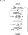
- FIG. 13 is a flowchart showing a first engine starting control
- FIG. 14 is a time chart showing temporal changes in speeds of the first motor and the engine, and engagement pressure of the clutch during execution of the first engine starting control;
- FIG. 15 is a nomographic diagram indicating speeds of the rotary elements and an engagement states at point t 2 in FIG. 14 ;
- FIG. 16 is a flowchart showing a second engine starting control
- FIG. 17 is a time chart showing temporal changes in speeds of the first motor and the engine, and engagement pressure of the clutch during execution of the second engine starting control;
- FIG. 18 is a nomographic diagram indicating speeds of the rotary elements and an engagement states at point t 12 in FIG. 17 ;
- FIG. 19 is a flowchart showing a third engine starting control.
- FIG. 20 is a time chart showing temporal changes in speeds of the first motor and the engine, and engagement pressure of the clutch during execution of the third engine starting control.
- a prime mover of the vehicle Ve includes an engine 1 , a first motor (referred to as “MG 1 ” in the drawings) 2 , and a second motor (referred to as “MG 2 ” in the drawings) 3 .
- MG 1 first motor
- MG 2 second motor
- a gasoline engine and a diesel engine may be used as the engine 1
- a motor-generator such as a permanent magnet synchronous motor and an induction motor may be used as the first motor 2 and the second motor 3 .
- An output shaft 4 of the engine 1 is connected to a flywheel 5 , and a torque limiter 6 is connected to the flywheel 5 to limit a transmission torque.
- the torque limiter 6 includes a dry clutch that pushes an annular rotary member 7 onto the flywheel 5 by a diaphragm spring. When a torque greater than an upper limit torque to the flywheel 5 or the rotary member 7 , torque transmission between the flywheel 5 and the rotary member 7 is interrupted to prevent an excessive torque transmission.
- An output member 8 is held in the rotary member 7 while being allowed to rotate relatively to the rotary member 7 , and a plurality of coil springs 9 are interposed between the rotary member 7 and the output member 8 to elastically transmit torque of the rotary member 7 to the output member 8 .
- the rotary member 7 , the output member 8 , and the coil springs 9 form a spring damper 10 so that the torque of the rotary member 7 is transmitted to the output member 8 while suppressing pulsation.
- the output member 8 is connected to an input shaft 11 of a transmission T, and the input shaft 11 is connected to a power split device 12 as a single-pinion planetary gear unit. Accordingly, the power split device 12 serves as a “differential mechanism” of the embodiment.
- the power split device 12 includes: a sun gear 13 as a third rotary element; a ring gear 14 as a second rotary element arranged concentrically with the sun gear 13 ; a plurality of planetary gears 15 interposed between the sun gear 13 and the ring gear 14 while keeping predetermined intervals; and a carrier 16 as a first rotary element that supports the planetary gears 15 while allowing to revolve around the sun gear 13 .
- the carrier 16 is connected to the input shaft 11 , the sun gear 13 is connected to the first motor 2 through a clutch 17 , and the ring gear 14 is connected to drive wheels 19 through a gear train 18 .
- torque of the engine 1 and torque of the first motor 2 are delivered to the sun gear 13 , and the ring gear 14 is connected the drive wheels 19 to transmit torque therebetween.
- the torque of the engine 1 is delivered to the drive wheels 19 though the power split device 12 by establishing a reaction torque by the first motor 2 .
- the first motor 2 generates torque in a direction to reduce a speed thereof in most cases so that power of the engine 1 is partially converted into electric power by the first motor 2 .
- a double-pinion planetary gear unit may also be used as the power split device 12 instead of the single-pinion planetary gear unit.
- a ring gear is connected to the engine 1
- a carrier is connected to the drive wheels 19
- a sun gear is connected to the first motor 2 through the clutch 17 .
- a Ravigneaux planetary gear unit having four rotary elements may also be used as the power split device 12 instead of the single-pinion planetary gear unit.
- the ring gear 14 has a predetermined length in an axial direction, and first external teeth 20 are formed on an outer circumferential face of one end of the ring gear 14 .
- a counter driven gear 22 is fitted onto one end of a countershaft 21 extending parallel to the input shaft 11 while meshing with the first external teeth 20 of the ring gear 14
- a counter drive gear 23 is fitted onto other end of the countershaft 21 while meshing with a ring gear 25 of a differential gear unit 24 to transmit power to the drive wheels 19 .
- the second motor 3 is arranged between the ring gear 14 and the drive wheels 19 in such a manner that an output shaft 27 of the second motor 3 extends parallel to the countershaft 21 , and an output gear 26 is fitted onto a leading end of the output shaft 27 to be meshed with the counter driven gear 22 .
- Second external teeth 28 are formed on an outer circumferential face of other end of the ring gear 14 , and a first pinion gear 29 fitted onto one end of a first input shaft 30 is meshed with the second external teeth 28 .
- Other end of the first input shaft 30 is connected to a driveshaft 33 of a mechanical oil pump (to be abbreviated as the “MOP” hereinafter) 32 through a first one-way clutch (to be abbreviated as the “first OWC” hereinafter) 31 .
- MOP mechanical oil pump
- first OWC first one-way clutch
- An output gear 35 is fitted onto the output shaft 34 of the first motor 2 , and a second pinion gear 36 is fitted onto one end of a second input shaft 37 extending coaxially with the first pinion gear 29 to be meshed with the output gear 35 .
- Other end of the second input shaft 37 is connected to the driveshaft 33 of the MOP 32 through a second one-way clutch (to be abbreviated as the “second OWC” hereinafter) 38 .
- the first OWC 31 is brought into engagement when the first input shaft 30 is rotated in the counter direction to a rotational direction of the engine 1 (as will be simply called the “counter direction” hereinafter) to apply torque to the driveshaft 33 .
- the second OWC 38 is brought into engagement when the second input shaft 37 is rotated in the counter direction to apply torque to the driveshaft 33 . That is, the first OWC 31 is brought into engagement when the ring gear 14 is rotated in the rotational direction of the engine 1 (as will be simply called the “forward direction” hereinafter) to apply torque to the driveshaft 33 . Likewise, the second OWC 38 is brought into engagement when the first motor 2 is rotated in the forward direction to apply torque to the driveshaft 33 .
- the first input shaft 30 is connected to the driveshaft 33 through the first OWC 31
- the second input shaft 37 is connected to the driveshaft 33 through the second OWC 38
- the engagement direction of the first OWC 31 to engage the first input shaft 30 with the driveshaft 33 and the engagement direction of the second OWC 38 to engage the second input shaft 37 with the driveshaft 33 are identical to each other. That is, when the first input shaft 30 is rotated at a speed higher than a rotational speed of the second input shaft 37 , the first OWC 31 is brought into engagement so that the first input shaft 30 is rotated integrally with the driveshaft 33 .
- the second input shaft 37 is rotated at a speed lower than a rotational speed of the driveshaft 33 and hence the second OWC 38 is not brought into engagement.
- the second input shaft 37 is rotated at a speed higher than a rotational speed of the first input shaft 30
- the second OWC 38 is brought into engagement so that the second input shaft 37 is rotated integrally with the driveshaft 33 .
- the first input shaft 30 is rotated at a speed lower than a rotational speed of the driveshaft 33 and hence the first OWC 31 is not brought into engagement. That is, torque is applied to the MOP 32 from one of the first input shaft 30 and the second input shaft 37 rotated at the higher speed in the counter direction.
- the input shaft applying the torque to the MOP 32 is switched automatically.
- a clutch 17 is disposed on the output shaft 34 .
- the clutch 17 includes a first rotary member 17 a connected to the first motor 2 and a second rotary member 17 b connected to the sun gear 13 .
- the clutch 17 is actuated hydraulically or electromagnetically, and a torque transmitting capacity of the clutch 17 is changed by controlling a contact pressure between the first rotary member 17 a and the second rotary member 17 b .
- the clutch 17 is in disengagement, the torque will not be transmitted to the drive wheels 19 through the power split device 12 . In this situation, therefore, the vehicle Ve is allowed to be powered by the second motor 3 while stopping the engine 1 .
- a speed of the first motor 2 may be altered arbitrarily in this situation.
- the vehicle Ve is provided with an electronic control unit (to be abbreviated as the “ECU” hereinafter) 39 as a controller.
- the ECU 39 is composed mainly of a microcomputer, and data from an accelerator sensor for detecting an accelerator position, a vehicle speed sensor for detecting a vehicle speed, a shift position sensor for detecting a shift position, an SOC sensor for detecting a state of charge (to be abbreviated as the “SOC” hereinafter) level of a battery connected to the motors 2 and 3 , an engine speed sensor for detecting an engine speed, a motor speed sensor for detecting speeds of the motors 2 and 3 (those sensors are not shown) are sent to the ECU 39 .
- the ECU 39 executes calculation based on the incident data using maps and formulas installed in advance, and transmits calculation result in the form of command signal. For example, the ECU 39 transmits command signals of an ignition timing of the engine 1 , a fuel injection amount, current values and voltage values of the electricity supplied to the motors 2 and 3 , a hydraulic value or a current value to engage the clutch 17 and so on.
- An operating mode of the vehicle Ve may be selected from hybrid vehicle mode (to be abbreviated as the “HV mode” hereinafter) in which an output torque of the engine 1 is delivered to the drive wheels 19 through the power split device 12 to propel the vehicle Ve, and an electric vehicle mode (to be abbreviated as the “EV mode” hereinafter) in which an output torque of the second motor 3 is delivered to the drive wheels 19 to propel the vehicle Ve while stopping the engine 1 .
- the MOP 32 may be driven even when the vehicle Ve is stopped.
- Conditions of the vehicle Ve in each operating mode, and rotational speeds of the rotary elements of the power split device 12 and the first motor 2 are indicated in FIGS. 2 to 10 .
- the nomographic diagrams shown in FIGS. 2 to 10 will be explained on the assumption that a gear ratio between the second external teeth 28 and the first pinion gear 29 , and a gear ratio between the output gear 35 and the second pinion gear 36 are “1”, for the sake of explanation.
- FIG. 2 shows an example of driving the MOP 32 when the vehicle Ve is stopped while stopping the engine 1 .
- the ring gear 14 is connected to the drive wheels 19 through the gear train 18 , and hence a rotation of the ring gear 14 is stopped when the vehicle Ve is stopped. In this situation, therefore, torque may not be applied to the MOP 32 from the ring gear 14 .
- the second motor 3 is also connected to the drive wheels 19 through the counter driven gear 22 and so on, and hence rotations of the second motor 3 and the rotary elements 13 , 14 , and 15 of the power split device 12 are also stopped when the vehicle Ve is stopped while stopping the engine 1 .
- the MOP 32 may be required to be driven for the purpose of cooling gears of the gear train 18 and the power split device 12 .
- the clutch 17 is disengaged to drive the power split device 12 and the first motor 2 separately.
- the clutch 17 is disengaged to allow the first motor 2 to be rotated at a desired speed while stopping the engine 1 in the stopping vehicle Ve.
- the MOP 32 is allowed to be driven by the torque applied from the second input shaft 37 while stopping the engine 1 , by thus disengaging the clutch 17 while adjusting the rotational speed of the first motor 2 .
- the battery may be charged by activating the engine 1 to operate the first motor 2 as a generator by the engine 1 .
- FIG. 3 shows a situation in which the battery is charged in the stopping vehicle Ve by activating the engine 1 to operate the first motor 2 as a generator.
- the torque cannot be applied to the MOP 32 from the ring gear 14 , and the rotations of the second motor 3 and the power split device 12 are also stopped.
- the first motor 2 is driven to serve as a generator by activating the engine 1 .
- the MOP 32 may also be required to be driven for the purpose of cooling gears of the gear train 18 and the power split device 12 .
- the engine 1 When charging the battery while driving the MOP 32 in the stopping vehicle Ve, the engine 1 generates power not only to charge the battery but also to drive the MOP 32 .
- the clutch 17 is engaged to apply the power to the first motor 2 .
- the first motor 2 generates torque to maintain a speed of the first motor 2 at a speed possible keep a speed of the engine 1 to an optimally fuel efficient speed in accordance with a gear ratio of the power split device 12 .
- the first motor 2 generates the torque in the forward direction to reduce the speed of the first motor 2 , and consequently the first motor 2 generates electricity.
- the power of the engine 1 delivered to the output shaft 34 of the first motor 2 through the clutch 17 is partially delivered to the driveshaft 33 through the second input shaft 37 to drive the MOP 32 .
- the first motor 2 is allowed not only to charge the battery but also to drive the MOP 32 by activating the engine 1 while engaging the clutch 17 .
- FIG. 4 shows a situation in which the MOP 32 is driven during forward propulsion of the vehicle Ve in the EV mode while stopping the engine 1 and disengaging the clutch 17 .
- the torque may be applied to the MOP 32 from the first input shaft 30 or the second input shaft 37 .
- the ring gear 14 is rotated at a speed in accordance with the vehicle speed, and the second motor 3 is rotated at the forward direction to propel the vehicle Ve.
- the sun gear 13 is rotated in the counter direction at a speed governed by the rotational speed of the ring gear 14 and the gear ratio of the power split device 12 .
- the sun gear 13 and the first motor 2 are allowed to rotate relatively to each other.
- the clutch 17 would be kept in engagement when mechanical failure occurs in the clutch 17 .
- the clutch 17 may be engaged for the preparation of cranking of the engine 1 to shift the operating mode to the HV mode.
- FIG. 5 The situation of such cases during forward propulsion in the EV mode is shown in FIG. 5 .
- the ring gear 14 is also rotated at a speed in accordance with the vehicle speed, and the second motor 3 is also rotated at the forward direction to propel the vehicle Ve.
- the sun gear 13 is also rotated in the counter direction at the speed governed by the rotational speed of the ring gear 14 and the gear ratio of the power split device 12 .
- FIG. 6 shows a situation in which the MOP 32 is driven during forward propulsion of the vehicle Ve in the HV mode at a low speed.
- the ring gear 14 is rotated at a relatively low speed.
- the engine 1 is operated at a speed that is determined based on a required drive force in line with an optimally fuel efficient curve, and that is higher than the speed of the ring gear 14 .
- the sun gear 13 is also rotated at the speed governed by the rotational speeds of the ring gear 14 and the carrier 16 , and the gear ratio of the power split device 12 .
- the rotational speed of the sun gear 13 of this case is higher than those of the ring gear 14 and the carrier 16 .
- the first motor 2 in order to deliver the torque of the engine 1 to the drive wheels 19 , the first motor 2 generates a reaction torque and the clutch 17 is engaged. Consequently, the first motor 2 is rotated at a same speed as the sun gear 13 . Thus, in the situation shown in FIG. 6 , the first motor is rotated at the speed higher than that of the ring gear 14 in the forward direction so that the torque is applied to the MOP 32 from the first input shaft 30 .
- FIG. 7 shows a situation in which the MOP 32 is driven during forward propulsion of the vehicle Ve in the HV mode at a high speed.
- the ring gear 14 is rotated at a speed higher than that of the engine, and the sun gear 13 is rotated at a speed lower than that of the carrier 16 .
- the torque of the ring gear 14 is applied to the MOP 32 from the first input shaft 30 .
- the MOP 32 may also be driven even during reverse propulsion of the vehicle Ve.
- FIG. 8 shows a situation in which the MOP 32 is driven during reverse propulsion of the vehicle Ve in the EV mode while stopping the engine 1 and disengaging the clutch 17 .
- the drive wheels 19 are rotated in the backward direction and hence the second motor 3 and the ring gear 14 are rotated in the counter direction.
- the sun gear 13 is rotated in the opposite direction to the rotational direction of the ring gear 14 . That is, the sun gear 13 is rotated in the forward direction at a speed governed by the rotational speed of the rig gear 14 and the gear ratio of the power split device 12 .
- FIG. 9 shows a situation in which the MOP 32 is driven during reverse propulsion of the vehicle Ve in the EV mode while stopping the engine 1 and engaging the clutch 17 .
- the second motor 3 generates power not only to propel the vehicle Ve but also to drive the MOP 32 .
- the output power of the second motor 3 is partially delivered to the MOP 32 through the sun gear 13 , the clutch 17 , the output shaft 34 of the first motor 2 , the output gear 35 , and the second input shaft 37 .
- FIG. 10 shows a situation in which the MOP 32 is driven during reverse propulsion of the vehicle Ve in the HV mode.
- the engine 1 is activated and the ring gear 14 is rotated in the counter direction in accordance with the vehicle speed.
- the sun gear 13 is rotated in the forward direction at a speed governed by the rotational speeds of the carrier 16 and the ring gear 14 , and the gear ratio of the power split device 12 .
- the clutch 17 is in engagement so that the first motor 2 is rotated integrally with the sun gear 13 in the forward direction. Consequently, the torque is applied to the MOP 32 from the second input shaft 37 .
- the engine 1 is connected to the power split device 12 but the MOP 32 may be driven in every situation (including forward propulsion, reverse propulsion, and stopping of the vehicle Ve).
- the clutch 17 may be used as a torque limiter by controlling the engagement pressure. By thus using the clutch 17 as a torque limiter, excessive application of torque to the transmission T can be prevented without using the torque limiter 6 and hence the transmission T may be downsized. Specifically, the flywheel 5 may be reduced diametrically.
- step S 1 it is determined whether or not the vehicle Ve is propelled in the EV mode. If the vehicle Ve is propelled in the HV mode or the vehicle Ve is stopped so that the answer of step S 1 is NO, the routine terminates.
- step S 2 determines whether or not oil supply to the transmission T is required.
- step S 2 specifically, it is determined whether or not the gear train 18 has to be cooled or lubricated by the oil. For example, it is unnecessary to lubricate the gear train 18 in the following cases that the vehicle Ve is propelled in the reverse direction without applying large torque to the transmission T, and that the vehicle Ve is propelled in the forward direction or the reverse direction at a low speed while rotating the gears of the gear train 18 at a low speed. In those cases, accordingly, the answer of step S 2 will be NO.
- a temperature of the gear train 18 will not be raised excessively if a driving time of the vehicle Ve is short and hence the answer of step S 2 will also be NO in this case.
- a temperature sensor may be arranged in the transmission T. In this case, the answer of step S 2 will be NO if the temperature of the transmission T detected by the temperature sensor is lower than a threshold temperature.
- a torque sensor may also be arranged in the gear train 18 to detect torque of any of the rotary member of the gear train 18 . In this case, the answer of step S 2 will be NO if the torque of the rotary member of the gear train 18 detected by the torque sensor is smaller than a reference torque.
- step S 3 determines whether or not a discharge amount Din 1 of the oil discharged from the MOP 32 by driving the MOP 32 by the first input shaft 30 is greater than a required discharge amount Dr of the oil discharged from the MOP 32 .
- the required discharge amount Dr may be determined based on a driving time of the vehicle Ve, a temperature of the transmission T, or a torque applied to the transmission T.
- the discharge amount Din 1 may be obtained based on a rotational speed of the first input shaft 30 calculated based on a vehicle speed and a gear ratio of the power split device 12 .
- step S 2 If it is not necessary to supply oil to the transmission T so that the answer of step S 2 is NO, or if the discharge amount Din 1 is greater than the required discharge amount Dr so that the answer of step S 3 is YES, the routine progresses to step S 4 to disengage the clutch 17 and stop the first motor 2 . Thereafter, the routine terminates. In this case, the ring gear 14 is rotated at a speed governed by the vehicle speed so that the MOP 32 discharges the oil in accordance with the rotational speed of the ring gear 14 .
- step S 5 determines whether or not a discharge amount Den of the oil discharged from the MOP 32 in a case of engaging the clutch 17 is greater than the required discharge amount Dr of the oil discharged from the MOP 32 .
- the discharge amount Den may be obtained based on a rotational speed of the second input shaft 37 calculated based on a vehicle speed and the gear ratio of the power split device 12 .
- step S 5 If the discharge amount Den is greater than the required discharge amount Dr so that the answer of step S 5 is YES, the second input shaft 37 is rotated at a speed higher than that of the first input shaft 30 .
- the routine progresses to step S 6 to determine whether or not a speed N 1 of the first motor 2 in a case of engaging the clutch 17 falls within a predetermined range a determined based on a natural vibration frequency f of the first motor 2 .
- the natural vibration frequency f may be determined in advance based on a structure of the first motor 2 .
- step S 7 determines whether or not the clutch 17 is required to be engaged to satisfy another conditions. For example, the answer of step S 7 will be YES if the operating mode of the vehicle Ve is expected to be shifted from the EV mode to the HV mode.
- step S 7 If the clutch 17 is required to be engaged to satisfy another conditions so that the answer of step S 7 is YES, the routine progresses to step S 8 to engage the clutch 17 and stop current supply to the first motor 2 , and then the routine is terminates.
- step S 9 if the discharge amount Den is smaller than the required discharge amount Dr so that the answer of step S 5 is NO, if the speed N 1 of the first motor 2 falls within the predetermined range a so that the answer of step S 6 is YES, or if the clutch 17 is not required to be engaged to satisfy another conditions so that the answer of step S 7 is NO.
- step S 9 the clutch 17 is disengaged, and the rotational speed of the first motor 2 is adjusted to a speed out of the predetermined range a at which an actual discharge amount Da of the oil discharged from the MOP 32 is increased to be greater than the required discharge amount Dr. Thereafter, the routine terminates.
- the clutch 17 is disengaged in the case that it is unnecessary to supply oil to the transmission T, and in the case that the discharge amount Din 1 of the oil discharged from the MOP 32 by driving the MOP 32 by the first input shaft 30 is greater than the required discharge amount Dr of the MOP 32 .
- the output power of the second motor 3 will not be consumed to change the rotational speed of the first motor 2 even partially. That is, a power loss during propulsion of the EV mode may be reduced.
- the first motor 2 does not have to generate power to drive the MOP 32 , electric consumption may be reduced.
- the clutch 17 is also disengaged in the case that the rotational speed of the first motor 3 falls within the predetermined range a as a result of engaging the clutch 17 .
- the rotational speed of the first motor 2 is adjusted to the speed out of the predetermined range a. For this reason, noises and vibrations in the vehicle Ve resulting from vibrations of the first motor 2 may be suppressed.
- FIG. 12 shows a routine to be executed by the ECU 39 so as to select a pattern to start the engine 1 thereby shifting the operating mode from the EV mode to the HV mode.
- a clutch control system works properly to adjust a torque transmitting capacity of the clutch 17 causing a slip to a desired capacity.
- step S 11 may be made based on a fact that an actual speed of the first motor 2 detected by the sensor is changed in line with a theoretical change in the speed of the first motor 2 governed by a command signal transmitted from the ECU 39 . Even if the torque transmitting capacity of the clutch 17 cannot be controlled by the clutch control system, the routine shown in FIG. 12 will be continued if the ECU 39 determines that clutch 17 is still in a condition in which the first rotary member 17 a and the second rotary member 17 b can be engaged to each other completely and disengaged from each other completely.
- step S 12 determines whether or not a speed difference ⁇ N between the first rotary member 17 a and the second rotary member 17 b of the clutch 17 is equal to or greater than a threshold value ⁇ .
- the threshold value ⁇ is a slip limit value of the clutch 17
- the threshold value ⁇ may be determined based on heat resistance property of the clutch 17 .
- the speed difference ⁇ N may be obtained based on: a speed of the first motor 2 detected by the sensor; and a speed of the sun gear 13 obtained based on speeds of the vehicle Ve and the engine 1 detected by the sensors, and the gear ratio of the power split device 12 .
- step S 13 determines whether or not it is necessary to start the engine 1 promptly.
- Such determination at step S 13 may be made based on a fact that the accelerator pedal is depressed at a speed higher than a predetermined speed. In other words, at step S 13 , it is determined whether or not the engine 1 is required to be started promptly to generate high torque thereby accelerating the vehicle Ve quickly.
- step S 13 If the engine 1 is required to be started promptly so that the answer of step S 13 is YES, the routine progresses to step S 14 to execute an after-mentioned first engine starting control, and then the routine terminates. By contrast, if the engine 1 is not required to be started promptly so that the answer of step S 13 is NO, the routine progresses to step S 15 to execute an after-mentioned second engine starting control, and then the routine terminates.
- step S 11 If the clutch control system does not work properly so that the answer of step S 11 is NO, or if the speed difference ⁇ N is equal to or greater than the threshold value ⁇ so that the answer of step S 12 is YES, the routine progresses to step S 16 to execute an after-mentioned third engine starting control, and then the routine terminates.
- step S 21 transmission of an engine starting command is determined. For example, such determination at step S 21 may be made based on a fact that a flag to start the engine 1 is turned on upon satisfaction of the condition to shift the operating mode from the EV mode to the HV mode. If the engine starting command is not transmitted so that the answer of step S 21 is NO, the routine terminates. By contrast, if the engine starting command is transmitted so that the answer of step S 21 is YES, the routine progresses to step S 22 to raise an engagement pressure applied to the clutch 17 at a rate to increase an engine speed Ne of the engine 1 at a desired rate. Consequently, the engine speed Ne is increased toward a starting speed (or a target speed) Ns with an increase in the engagement pressure applied to the clutch 17 . In this situation, the first motor 2 is controlled in such a manner as to maintain the current speed.
- step S 23 it is determined at step S 23 whether or not the clutch 17 is engaged completely.
- step S 22 specifically, it is determined whether or not the speed of the sun gear 13 governed by the vehicle speed and the engine speed Ne is synchronized with the speed of the first motor 2 .
- step S 23 If the clutch 17 has not yet engaged completely while causing a slip so that the answer of step S 23 is NO, the routine returns to step S 22 to raise the engagement pressure applied to the clutch 17 continuously. By contrast, if the clutch 17 has been engaged completely so that the answer of step S 23 is YES, the routine progresses to step S 24 to increase the speed of the first motor 2 at a rate to increase the engine speed Ne at a desired rate. Consequently, the engine speed Ne is further increased toward the starting speed Ns with an increase in the speed of the first motor 2 .
- step S 25 it is determined whether or not the engine speed Ne is raised to the starting speed Ns.
- step S 25 If the engine speed Ne has not yet been raised to the starting speed Ns so that the answer of step S 25 is NO, the routine returns to step S 24 to raise the speed of the first motor 2 continuously. By contrast, if the engine speed Ne has been raised to the starting speed Ns so that the answer of step S 25 is YES, the routine progresses to step S 26 to execute fuel injection and ignition of the engine 1 . Thereafter, the routine terminates.
- Temporal changes in the speed of the first motor 2 , the engine speed Ne, and the engagement pressure applied to the clutch 17 in the case of starting the engine 1 by the first engine starting control are shown in FIG. 14 .
- the determination of complete engagement of the clutch 17 is made at step S 23 of the routine shown in FIG. 13 , and hence the speed of the first motor 2 is increased from point t 2 at the rate to increase the engine speed Ne at the desired rate. In this situation, therefore, the engine speed Ne is increased continuously without changing the change rate. Then, when the engine speed Ne is raised to the starting speed Ns at point t 3 , the speed of the first motor 2 is maintained. Conditions of the power split device 12 , the first input shaft 30 , and the second input shaft 37 in this situation are identical to those shown in FIG. 16 .
- the engine speed Ne may be raised promptly to the starting speed Ns upon transmission of the starting command. For this reason, the engine power may be delivered promptly to the drive wheels 19 . That is, the vehicle Ve may be accelerated quickly.
- a routine to execute the second engine starting control is shown in FIG. 16 .
- transmission of the engine starting command is also determined. If the engine starting command is not transmitted so that the answer of step S 31 is NO, the routine terminates. By contrast, if the engine starting command is transmitted so that the answer of step S 31 is YES, the routine progresses to step S 32 to increase a speed Nm of the first motor 2 to a target speed Nt to start the engine 1 .
- the target speed Nt of the first motor 2 is determined based on a speed of the sun gear 13 to be achieved when starting the engine 1 that is estimated based on a current speed of the ring gear 14 , the engine starting speed Ns, and the gear ratio of the power split device 12 . In this situation, since the clutch 17 is still in disengagement, drive force will not be changed even if the speed Nm of the first motor 2 is changed. For this reason, a change rate of the speed Nm of the first motor 2 may be set arbitrarily.
- step S 33 it is determined at step S 33 whether or not the speed Nm of the first motor 2 is raised to the target speed Nt based on an actual speed Nm of the first motor 2 detected by the sensor.
- step S 33 If the speed Nm of the first motor 2 has not yet been raised to the target speed Nt so that the answer of step S 33 is NO, the routine returns to step S 32 .
- the routine progresses to step S 34 to raise an engagement pressure applied to the clutch 17 at a rate to increase an engine speed Ne of the engine 1 at a desired rate. In this situation, the first motor 2 is controlled in such a manner as to maintain the current speed.
- step S 35 it is determined whether or not the engine speed Ne is raised to the starting speed Ns.
- step S 35 If the engine speed Ne has not yet been raised to the starting speed Ns so that the answer of step S 35 is NO, the routine returns to step S 34 to raise the engagement pressure applied to the clutch 17 continuously. By contrast, if the engine speed Ne has been raised to the starting speed Ns so that the answer of step S 35 is YES, the routine progresses to step S 36 to execute the fuel injection and the ignition of the engine 1 .
- Temporal changes in the speed of the first motor 2 , the engine speed Ne, and the engagement pressure applied to the clutch 17 in the case of starting the engine 1 by the second engine starting control are shown in FIG. 17 .
- dashed lines individually represent the speed Nm of the first motor 2 , the engine speed Ne, and the engagement pressure applied to the clutch 17 of the case in which the engine 1 is started by the first engine starting control.
- the speed Nm of the first motor 2 is raised to the target speed Nt at point t 12 .
- Conditions of the power split device 12 , the first input shaft 30 , and the second input shaft 37 in this situation are shown in FIG. 18 .
- the dashed circle represents the speed Nm of the first motor 2 at point t 11 before raised.
- the sun gear 13 , the ring gear 14 , and the carrier 16 of the power split device 12 are rotated at the speeds shown in FIG. 4 .
- the speed Nm of the first motor 2 is increased to the target speed Nt to start the engine 1 .
- the speed Nm of the first motor 2 is indicated on the assumption that the speed Nm of the first motor 2 to achieve the required discharge amount Dr of the oil discharged from the MOP 32 is lower than the speed Nm to start the engine 1 .
- the determination of increase in the speed Nm of the first motor 2 to the target speed Nt is made at step S 33 of the routine shown in FIG. 16 , and hence the engagement pressure applied to the clutch 17 is raised from point t 12 at the rate to increase an engine speed Ne of the engine 1 at the desired rate. Consequently, the torque of the first motor 2 is applied to the engine 1 so that the engine speed Ne is raised from point t 12 .
- the first motor 2 is controlled in such a manner as to maintain the current speed Nm.
- the speed Ne is raised to the starting speed Ns at point t 13 , the speed Nm of the first motor 2 is maintained.
- Conditions of the power split device 12 , the first input shaft 30 , and the second input shaft 37 in this situation are identical to those shown in FIG. 6 .
- the speed Nm of the first motor 2 does not have to be controlled after increasing the engine speed Ne. For this reason, the control may be simplified while preventing a temporal change in the change rate of the engine speed Ne during cranking.
- step S 41 transmission of the engine starting command is also determined. If the engine starting command is not transmitted so that the answer of step S 41 is NO, the routine terminates. By contrast, if the engine starting command is transmitted so that the answer of step S 41 is YES, the routine progresses to step S 42 to reduce the speed Nm of the first motor 2 to a current speed Np of the sun gear 13 . In other words, at step S 42 , the speed Nm of the first motor 2 is synchronized with the current speed Np of the sun gear 13 .
- the current speed Np of the sun gear 13 may be obtained based on the current speed of the ring gear 14 , the current engine speed Ne, and the gear ratio of the power split device 12 .
- a change rate of the speed Nm of the first motor 2 may be set arbitrarily.
- step S 43 it is determined at step S 43 whether or not the speed Nm of the first motor 2 is synchronized with the current speed Np of the sun gear 13 based on an actual speed of the first motor 2 Nm detected by the sensor.
- step S 43 If the speed Nm of the first motor 2 has not yet been synchronized with the current speed Np of the sun gear 13 so that the answer of step S 43 is NO, the routine returns to step S 42 to reduce the speed Nm of the first motor 2 continuously. By contrast, if the speed Nm of the first motor 2 has been synchronized with the current speed Np of the sun gear 13 so that the answer of step S 43 is YES, the routine progresses to step S 44 to engage the clutch 17 . In this situation, since the speed Nm of the first motor 2 has been synchronized with the current speed Np of the sun gear 13 , an engagement shock of the clutch 17 may be reduced even if the clutch 17 is engaged abruptly. In this situation, therefore, it is preferable to raise the engagement pressure applied to the clutch 17 abruptly to bring the clutch 17 into complete engagement promptly so as to start the engine 1 promptly.
- step S 45 the speed Nm of the first motor 2 is increased at the rate to increase the engine speed Ne at the desired rate. Consequently, the engine speed Ne is further increased with an increase in the speed Nm of the first motor 2 .
- step S 46 it is determined whether or not the engine speed Ne is raised to the starting speed Ns.
- step S 46 If the engine speed Ne has not yet been raised to the starting speed Ns so that the answer of step S 46 is NO, the routine returns to step S 45 to increase the speed Nm of the first motor 2 continuously. By contrast, if the engine speed Ne has been raised to the starting speed Ns so that the answer of step S 46 is YES, the routine progresses to step S 47 to execute the fuel injection and the ignition of the engine 1 .
- Temporal changes in the speed of the first motor 2 , the engine speed Ne, and the engagement pressure applied to the clutch 17 in the case of starting the engine 1 by the third engine starting control are shown in FIG. 20 .
- dashed lines individually represent the speed Nm of the first motor 2 , the engine speed Ne, and the engagement pressure applied to the clutch 17 of the case in which the engine 1 is started by the first engine starting control.
- engagement shock of the clutch 17 may be reduced even if the clutch control system does not work properly.
- the clutch 17 since the clutch 17 is engaged without causing a slip, the clutch 17 may be prevented from being heated excessively. That is, damage on the clutch 17 can be limited. For this reason, a clutch the heat resistance thereof is not so high may be used as the clutch 17 .
- the first input shaft 30 may also be connected to the sun gear 13 or the carrier 16 instead of the ring gear 14 .
- the sun gear 13 will be rotated in the counter direction and the carrier 16 is stopped during propulsion in the EV mode, therefore, torque may not be applied to the MOP 32 from the first input shaft 30 .
- the clutch 17 is disengaged and the first motor 2 is driven during propulsion in the EV mode.
- a speed difference between the first rotary member 17 a and the second rotary member 17 b may be increased when engaging the clutch 17 , and hence the rotational speed of the first rotary member 17 a is synchronized with the rotational speed of the second rotary member 17 b while rotating the first motor 2 in the counter direction.
- torque transmission to the MOP 32 is stopped when the first motor 2 starts rotating in the counter direction and hence the MOP 32 is inactivated temporarily.
- the first input shaft 30 is connected to the ring gear 14 so that the MOP 32 is driven continuously by the ring gear 14 even during the synchronization of the clutch 17 . For this reason, it is preferable to connect the first input shaft 30 to the ring gear 14 .
Landscapes
- Engineering & Computer Science (AREA)
- Mechanical Engineering (AREA)
- Transportation (AREA)
- Chemical & Material Sciences (AREA)
- Combustion & Propulsion (AREA)
- General Engineering & Computer Science (AREA)
- Automation & Control Theory (AREA)
- Physics & Mathematics (AREA)
- Fluid Mechanics (AREA)
- Hybrid Electric Vehicles (AREA)
- Electric Propulsion And Braking For Vehicles (AREA)
- Arrangement Of Transmissions (AREA)
Abstract
Description
Claims (19)
Applications Claiming Priority (2)
| Application Number | Priority Date | Filing Date | Title |
|---|---|---|---|
| JP2016251768A JP6540680B2 (en) | 2016-12-26 | 2016-12-26 | Hybrid vehicle |
| JP2016-251768 | 2016-12-26 |
Publications (2)
| Publication Number | Publication Date |
|---|---|
| US20180178779A1 US20180178779A1 (en) | 2018-06-28 |
| US10543835B2 true US10543835B2 (en) | 2020-01-28 |
Family
ID=62625373
Family Applications (1)
| Application Number | Title | Priority Date | Filing Date |
|---|---|---|---|
| US15/844,805 Expired - Fee Related US10543835B2 (en) | 2016-12-26 | 2017-12-18 | Hybrid vehicle |
Country Status (3)
| Country | Link |
|---|---|
| US (1) | US10543835B2 (en) |
| JP (1) | JP6540680B2 (en) |
| CN (1) | CN108237894B (en) |
Families Citing this family (10)
| Publication number | Priority date | Publication date | Assignee | Title |
|---|---|---|---|---|
| JP6343596B2 (en) * | 2015-10-06 | 2018-06-13 | 本田技研工業株式会社 | Dual clutch transmission |
| JP6540680B2 (en) * | 2016-12-26 | 2019-07-10 | トヨタ自動車株式会社 | Hybrid vehicle |
| JP6607202B2 (en) * | 2017-01-10 | 2019-11-20 | トヨタ自動車株式会社 | Drive device |
| JP7192408B2 (en) * | 2018-11-06 | 2022-12-20 | トヨタ自動車株式会社 | Hybrid vehicle control device |
| CN109177968B (en) * | 2018-11-06 | 2020-02-07 | 吉林大学 | Drive mode control method of power split type hybrid electric vehicle |
| CN111634193B (en) * | 2019-03-01 | 2024-05-14 | 广汽埃安新能源汽车有限公司 | Torque direction determination method, device, vehicle, computer equipment and storage medium |
| CN111516478A (en) * | 2020-03-23 | 2020-08-11 | 潍柴动力股份有限公司 | Vehicle transmission system and vehicle |
| JP2023000144A (en) * | 2021-06-17 | 2023-01-04 | 本田技研工業株式会社 | VEHICLE DRIVE MECHANISM CONTROL DEVICE AND VEHICLE DRIVE MECHANISM CONTROL METHOD |
| DE102021122046A1 (en) | 2021-08-26 | 2023-03-02 | Bayerische Motoren Werke Aktiengesellschaft | Transmission arrangement, motor vehicle with a transmission arrangement and method for operating a transmission arrangement |
| US12291102B2 (en) * | 2023-01-17 | 2025-05-06 | Dana Belgium N.V. | Pump assembly in a transmission and pump assembly operating method |
Citations (16)
| Publication number | Priority date | Publication date | Assignee | Title |
|---|---|---|---|---|
| JPH08324262A (en) | 1995-05-30 | 1996-12-10 | Aqueous Res:Kk | Hybrid vehicle |
| US20100075798A1 (en) * | 2008-09-24 | 2010-03-25 | Jatco Ltd | Control apparatus for hybrid vehicle |
| US20100228452A1 (en) * | 2009-03-09 | 2010-09-09 | Aisin Seiki Kabushiki Kaisha | Hydraulic pressure controlling apparatus |
| US20100228451A1 (en) * | 2009-03-09 | 2010-09-09 | Aisin Seiki Kabushiki Kaisha | Hydraulic pressure controlling apparatus |
| JP2011037329A (en) | 2009-08-07 | 2011-02-24 | Toyota Motor Corp | Power train of vehicle |
| JP2012144172A (en) | 2011-01-13 | 2012-08-02 | Toyota Motor Corp | Controller for hybrid vehicle |
| US20130124027A1 (en) * | 2010-07-21 | 2013-05-16 | Nissan Motor Co., Ltd. | Control apparatus and method for hybrid vehicle |
| US20130231815A1 (en) * | 2010-10-22 | 2013-09-05 | Nissan Motor Co., Ltd. | Hybrid vehicle control device |
| US20130297135A1 (en) * | 2011-01-28 | 2013-11-07 | Jatco Ltd | Hybrid vehicle control device |
| JP2013252734A (en) | 2012-06-05 | 2013-12-19 | Toyota Motor Corp | Control device of hybrid vehicle |
| JP2015054579A (en) | 2013-09-11 | 2015-03-23 | トヨタ自動車株式会社 | Vehicle control device |
| US20150337953A1 (en) * | 2013-01-29 | 2015-11-26 | Aisin Aw Co., Ltd. | Vehicular power transmission device |
| US20150360682A1 (en) * | 2013-01-31 | 2015-12-17 | Jatco Ltd | Control device for automatic transmission |
| JP2016130115A (en) | 2015-01-15 | 2016-07-21 | トヨタ自動車株式会社 | Hybrid vehicle drive control device |
| JP2016150674A (en) | 2015-02-18 | 2016-08-22 | トヨタ自動車株式会社 | Hybrid vehicle |
| US20180178779A1 (en) * | 2016-12-26 | 2018-06-28 | Toyota Jidosha Kabushiki Kaisha | Hybrid vehicle |
Family Cites Families (5)
| Publication number | Priority date | Publication date | Assignee | Title |
|---|---|---|---|---|
| DE19917665A1 (en) * | 1999-04-19 | 2000-10-26 | Zahnradfabrik Friedrichshafen | Hybrid drive for motor vehicle has IC engine coupled to motor through clutch and to gears through second clutch, second motor coupled permanently to gears forming hybrid drive with IC engine |
| US8187147B2 (en) * | 2008-03-27 | 2012-05-29 | GM Global Technology Operations LLC | Hydraulic control system for multi-mode hybrid transmission and method of regulating the same |
| JP5108071B2 (en) * | 2010-09-22 | 2012-12-26 | 富士重工業株式会社 | Drive device for hybrid vehicle |
| US9353692B2 (en) * | 2011-12-12 | 2016-05-31 | Fca Us Llc | Start-up strategy for hybrid powertrain |
| US9827978B2 (en) * | 2015-02-10 | 2017-11-28 | Ford Global Technologies, Llc | Method of engaging transmission system of a hybrid vehicle |
-
2016
- 2016-12-26 JP JP2016251768A patent/JP6540680B2/en not_active Expired - Fee Related
-
2017
- 2017-12-18 US US15/844,805 patent/US10543835B2/en not_active Expired - Fee Related
- 2017-12-25 CN CN201711417033.6A patent/CN108237894B/en not_active Expired - Fee Related
Patent Citations (17)
| Publication number | Priority date | Publication date | Assignee | Title |
|---|---|---|---|---|
| JPH08324262A (en) | 1995-05-30 | 1996-12-10 | Aqueous Res:Kk | Hybrid vehicle |
| US20100075798A1 (en) * | 2008-09-24 | 2010-03-25 | Jatco Ltd | Control apparatus for hybrid vehicle |
| US20100228452A1 (en) * | 2009-03-09 | 2010-09-09 | Aisin Seiki Kabushiki Kaisha | Hydraulic pressure controlling apparatus |
| US20100228451A1 (en) * | 2009-03-09 | 2010-09-09 | Aisin Seiki Kabushiki Kaisha | Hydraulic pressure controlling apparatus |
| JP2011037329A (en) | 2009-08-07 | 2011-02-24 | Toyota Motor Corp | Power train of vehicle |
| US20130124027A1 (en) * | 2010-07-21 | 2013-05-16 | Nissan Motor Co., Ltd. | Control apparatus and method for hybrid vehicle |
| US20130231815A1 (en) * | 2010-10-22 | 2013-09-05 | Nissan Motor Co., Ltd. | Hybrid vehicle control device |
| JP2012144172A (en) | 2011-01-13 | 2012-08-02 | Toyota Motor Corp | Controller for hybrid vehicle |
| US20130297135A1 (en) * | 2011-01-28 | 2013-11-07 | Jatco Ltd | Hybrid vehicle control device |
| JP2013252734A (en) | 2012-06-05 | 2013-12-19 | Toyota Motor Corp | Control device of hybrid vehicle |
| US20150337953A1 (en) * | 2013-01-29 | 2015-11-26 | Aisin Aw Co., Ltd. | Vehicular power transmission device |
| US20150360682A1 (en) * | 2013-01-31 | 2015-12-17 | Jatco Ltd | Control device for automatic transmission |
| JP2015054579A (en) | 2013-09-11 | 2015-03-23 | トヨタ自動車株式会社 | Vehicle control device |
| JP2016130115A (en) | 2015-01-15 | 2016-07-21 | トヨタ自動車株式会社 | Hybrid vehicle drive control device |
| JP2016150674A (en) | 2015-02-18 | 2016-08-22 | トヨタ自動車株式会社 | Hybrid vehicle |
| WO2016132203A1 (en) | 2015-02-18 | 2016-08-25 | Toyota Jidosha Kabushiki Kaisha | Hybrid vehicle |
| US20180178779A1 (en) * | 2016-12-26 | 2018-06-28 | Toyota Jidosha Kabushiki Kaisha | Hybrid vehicle |
Also Published As
| Publication number | Publication date |
|---|---|
| JP6540680B2 (en) | 2019-07-10 |
| CN108237894A (en) | 2018-07-03 |
| US20180178779A1 (en) | 2018-06-28 |
| CN108237894B (en) | 2020-12-22 |
| JP2018103777A (en) | 2018-07-05 |
Similar Documents
| Publication | Publication Date | Title |
|---|---|---|
| US10543835B2 (en) | Hybrid vehicle | |
| US9956954B2 (en) | Control system for hybrid vehicle | |
| US8050830B2 (en) | Driving apparatus for vehicle | |
| US9896088B2 (en) | Drive control system for hybrid vehicle | |
| US8412396B2 (en) | Electric launch of a hybrid vehicle having a belt alternator starter and a dual clutch transmission | |
| US9291218B2 (en) | Vehicle control system | |
| US20170259809A1 (en) | Control system for hybrid vehicle | |
| US10017042B2 (en) | Control system for hybrid vehicle | |
| US9896084B2 (en) | Control system for hybrid vehicle | |
| US9682697B2 (en) | Control system for hybrid vehicle | |
| US20160214598A1 (en) | Driving force control system for a vehicle | |
| JPWO2017056910A1 (en) | Control device | |
| US11242046B2 (en) | Control system for hybrid vehicle | |
| US9925976B2 (en) | Hybrid electric vehicle drive apparatus | |
| US10023171B2 (en) | Power transmission device | |
| US10202113B2 (en) | Engine starting control system for hybrid vehicle | |
| US9771065B2 (en) | Vehicle control system | |
| US20160325735A1 (en) | Control system for power transmission unit | |
| US10293828B2 (en) | Engine starting system | |
| WO2015159661A1 (en) | Hybrid vehicle | |
| US10308136B2 (en) | Vehicle control system | |
| US20190299976A1 (en) | Control system for vehicle | |
| US11447125B2 (en) | Vehicle control system |
Legal Events
| Date | Code | Title | Description |
|---|---|---|---|
| FEPP | Fee payment procedure |
Free format text: ENTITY STATUS SET TO UNDISCOUNTED (ORIGINAL EVENT CODE: BIG.); ENTITY STATUS OF PATENT OWNER: LARGE ENTITY |
|
| STPP | Information on status: patent application and granting procedure in general |
Free format text: DOCKETED NEW CASE - READY FOR EXAMINATION |
|
| AS | Assignment |
Owner name: TOYOTA JIDOSHA KABUSHIKI KAISHA, JAPAN Free format text: ASSIGNMENT OF ASSIGNORS INTEREST;ASSIGNOR:INAGAWA, TOMOKAZU;REEL/FRAME:045495/0657 Effective date: 20180123 |
|
| STPP | Information on status: patent application and granting procedure in general |
Free format text: NON FINAL ACTION MAILED |
|
| STPP | Information on status: patent application and granting procedure in general |
Free format text: RESPONSE TO NON-FINAL OFFICE ACTION ENTERED AND FORWARDED TO EXAMINER |
|
| STPP | Information on status: patent application and granting procedure in general |
Free format text: NOTICE OF ALLOWANCE MAILED -- APPLICATION RECEIVED IN OFFICE OF PUBLICATIONS |
|
| STCF | Information on status: patent grant |
Free format text: PATENTED CASE |
|
| FEPP | Fee payment procedure |
Free format text: MAINTENANCE FEE REMINDER MAILED (ORIGINAL EVENT CODE: REM.); ENTITY STATUS OF PATENT OWNER: LARGE ENTITY |
|
| LAPS | Lapse for failure to pay maintenance fees |
Free format text: PATENT EXPIRED FOR FAILURE TO PAY MAINTENANCE FEES (ORIGINAL EVENT CODE: EXP.); ENTITY STATUS OF PATENT OWNER: LARGE ENTITY |
|
| STCH | Information on status: patent discontinuation |
Free format text: PATENT EXPIRED DUE TO NONPAYMENT OF MAINTENANCE FEES UNDER 37 CFR 1.362 |
|
| FP | Lapsed due to failure to pay maintenance fee |
Effective date: 20240128 |