US1054092A - Trolley. - Google Patents
Trolley. Download PDFInfo
- Publication number
- US1054092A US1054092A US72474512A US1912724745A US1054092A US 1054092 A US1054092 A US 1054092A US 72474512 A US72474512 A US 72474512A US 1912724745 A US1912724745 A US 1912724745A US 1054092 A US1054092 A US 1054092A
- Authority
- US
- United States
- Prior art keywords
- trolley
- shafts
- shaft
- web
- members
- Prior art date
- Legal status (The legal status is an assumption and is not a legal conclusion. Google has not performed a legal analysis and makes no representation as to the accuracy of the status listed.)
- Expired - Lifetime
Links
- 238000005192 partition Methods 0.000 description 3
- 244000273618 Sphenoclea zeylanica Species 0.000 description 1
- 239000004020 conductor Substances 0.000 description 1
- 238000010276 construction Methods 0.000 description 1
Images
Classifications
-
- B—PERFORMING OPERATIONS; TRANSPORTING
- B60—VEHICLES IN GENERAL
- B60L—PROPULSION OF ELECTRICALLY-PROPELLED VEHICLES; SUPPLYING ELECTRIC POWER FOR AUXILIARY EQUIPMENT OF ELECTRICALLY-PROPELLED VEHICLES; ELECTRODYNAMIC BRAKE SYSTEMS FOR VEHICLES IN GENERAL; MAGNETIC SUSPENSION OR LEVITATION FOR VEHICLES; MONITORING OPERATING VARIABLES OF ELECTRICALLY-PROPELLED VEHICLES; ELECTRIC SAFETY DEVICES FOR ELECTRICALLY-PROPELLED VEHICLES
- B60L5/00—Current collectors for power supply lines of electrically-propelled vehicles
- B60L5/04—Current collectors for power supply lines of electrically-propelled vehicles using rollers or sliding shoes in contact with trolley wire
- B60L5/10—Devices preventing the collector from jumping off
Definitions
- This invention relates to devices which are attached to the free end of poles, called trolley poles, the said trolley poles being ⁇ attached to the top or upper deok'- of cars which are propelled by electric motors.
- the object of this invention 'is to. obtain a trolley which will,'when the wheel thereof becomes 'disengagedfrom the overhead wire, automatically return to engagement therewith, to obviate thenecessity of the conductor, or other person in charge thereof, manually returning said trolley to said wire.
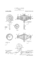
- FIG. l is a side elevation of a device embodying this invention.
- Fig. 2 is a rear elevation of said device.
- Fig. 3 is a longitudinal sectional view of the device.
- Fig. 4 is an end elevation of one of the rotating elements forming the trolley wheel of the device, exposing the interior thereof to view.
- F ig. 5 is a side elevation ⁇ of a supporting wheel, forming an element of the device.
- Fig. 6 is a side elevation of the base of the device, said baseforming the supporting member of the movable parts and shaft of said device.
- A is the base, and comprises the hollow stem a, in which the end ofA the trolley polev on which the device is secured may be inserted; and the web a to which the shafts B, B' are secured.
- Web a' is provided with hub a" through which said shafts extend.
- the lower edge of the web a' is considerably thicker than the upper edge the shafts B, B' are perpendicular to the side faces of said web.
- Said shafts consist of a single piece of shafting which is inserted through thehub a", and then bent so as o be atright angles to the faces of the we a'.
- D, D' are hollow cone shaped members which are, respectively, provided with right and left hand spiral grooves on the outerl faces thereof.
- flange d At the smaller end of mem- ⁇ ber D- there is the flange d, and at the ,eimaller end of member D' there is the flange f Flanges.
- d, al' are designed to insure the engagement of said members D, D', with the trolley wire in case the said members jump, or become disengaged from the said wire.
- ends of said members D, D', on thevshafts B, B', and said bearings rotate. freely on said shafts.
- the larger ends of said members D, D' are supported on .the supporting wheels C, C', respectively, and said wheels revolve freely on said shafts B, B'.
- E is a rib on the forward edge of the web a and E' is a like rib on the rear edge of said web.
- Ribs E, E', cover so much of the d" are the bearings of the smaller larger ends of the members D, D', as are not substantially in contact with each other; and the purpose of these ribs is to receive thereon the trolley wire when the trolley-is not in position so that said wire is not in contact with the exposed faces e, e of .said
- iF is ana erture which is adapted to rie-y ceive the en vof a cord or rope.
- G, G' are nuts on the ends of shafts B, B', respectively..A
- the ends of shafts B, B' are respectively provided with screw threads g, and said nuts G, G' are rovided with corresponding screw threa s.
- - H are cotter pins which are put through apertures provided therefor in -said nuts G, G' and shafts B, B', in the ordinary .way of securing nuts bo shafts and bolts'to prevent the turning tliereof after adjustment.
- a trolley consisting of a base provided with ribs extending from said handle-par-l tially around the periphery of said web, in combination with a shaft secured in said web, with the parts of said shaft which pro.-
- cone shaped members respectively provided with right and left hand spirals and provided with circular faces on the larger ends thereof, saidcone shaped members hollow, and lrotatably mounted on said shaft, 4and supporting Wheels (C C) inserted in the larger ends thereof, said supporting Wheels rotatably mounted on said shaft, and means to secure said cone shaped members on said shaft and close to contact with said Web.
- la trolley roller consisting of a ltvvo part hollow cone shaped cylinder provided with right and left hand .spiral grooves on the periphery thereof and provided with circular faces o-n the larger ends thereof, respectively, in combination with a head' adapted to t on one end of a tenaces trolley pole, said head provided With a partitionl extending between the larger ends of the' two parte of the trolley, and said partition Wedge shaped in its vertical section, with a shaft rigidly secured in said partition midway of the ends of said shaft, and said ends respectively set perpendicular to the plane of the face of 4said partition which is adjacent thereto, bearing Wheels respectively fitting into the larger ends of the cone shaped parts of said trolley and rottably mounted on said'shaft, and the smalle ends of said cone shaped parts rotatably mounted on said shaft, nuts on the ends of said shaft, and means to secure said nuts -from turning.
Landscapes
- Engineering & Computer Science (AREA)
- Power Engineering (AREA)
- Transportation (AREA)
- Mechanical Engineering (AREA)
- Current-Collector Devices For Electrically Propelled Vehicles (AREA)
Description
JkLented Feb. 25, 1913.
TROLLEY.
APPLICATION FILED OGT- 9, 1912.
ANDREW DASZO AND ANDREW .BIELECH, F CvI-IICAGQ, ILLINOIS.
TROLLEY.
-' Specification of Letters Patent.
Patented Feb. 25, 1913.
Application filed October?, 1912. SeriaI No. 724,745.
To all 'whom it may concern.:
'Be it known that we, ANDREW DASZKO Aand ANDREW BIELECH, subjects of the Emperor of Austria-Hungary, and residents ofv Chicago, in the county of Cook and State of Illinols, 4have invented certain new and useful Improvements in Trolleys, of -which the following is a specification.
This invention relates to devices which are attached to the free end of poles, called trolley poles, the said trolley poles being `attached to the top or upper deok'- of cars which are propelled by electric motors.
and that it isnecessary to replace said trolley on said wire before the car can be propelled by said motor.' i
The object of this invention 'is to. obtain a trolley which will,'when the wheel thereof becomes 'disengagedfrom the overhead wire, automatically return to engagement therewith, to obviate thenecessity of the conductor, or other person in charge thereof, manually returning said trolley to said wire.
Further objects of this invention' are to obtain a trolley which is durable, simple in construction, not liable to, get out of order or break, and which is not of any considerable weight.
In the drawing Figure l is a side elevation of a device embodying this invention. Fig. 2 is a rear elevation of said device. Fig. 3 is a longitudinal sectional view of the device. Fig. 4 is an end elevation of one of the rotating elements forming the trolley wheel of the device, exposing the interior thereof to view. F ig. 5 is a side elevation` of a supporting wheel, forming an element of the device. And Fig. 6 is a side elevation of the base of the device, said baseforming the supporting member of the movable parts and shaft of said device. i
A reference letter -applied to designate a given part is used to indicate sald part throughout the several figures of the drawing, wherever the same appears.
A is the base, and comprises the hollow stem a, in which the end ofA the trolley polev on which the device is secured may be inserted; and the web a to which the shafts B, B' are secured. Web a' is provided with hub a" through which said shafts extend. The lower edge of the web a' is considerably thicker than the upper edge the shafts B, B' are perpendicular to the side faces of said web. Said shafts consist of a single piece of shafting which is inserted through thehub a", and then bent so as o be atright angles to the faces of the we a'.
thereof, as is well illust-rated in Fig. 3, and l C, C' lare supporting wheels whichrotate y.
freely on the shafts B, B', respectively.
D, D', are hollow cone shaped members which are, respectively, provided with right and left hand spiral grooves on the outerl faces thereof. At the smaller end of mem- `ber D- there is the flange d, and at the ,eimaller end of member D' there is the flange f Flanges. d, al' are designed to insure the engagement of said members D, D', with the trolley wire in case the said members jump, or become disengaged from the said wire. ends of said members D, D', on thevshafts B, B', and said bearings rotate. freely on said shafts. The larger ends of said members D, D', are supported on .the supporting wheels C, C', respectively, and said wheels revolve freely on said shafts B, B'. E is a rib on the forward edge of the web a and E' is a like rib on the rear edge of said web. Ribs E, E', cover so much of the d" are the bearings of the smaller larger ends of the members D, D', as are not substantially in contact with each other; and the purpose of these ribs is to receive thereon the trolley wire when the trolley-is not in position so that said wire is not in contact with the exposed faces e, e of .said
members D, D'. l
iF is ana erture which is adapted to rie-y ceive the en vof a cord or rope.
G, G' are nuts on the ends of shafts B, B', respectively..A The ends of shafts B, B' are respectively provided with screw threads g, and said nuts G, G' are rovided with corresponding screw threa s.- H are cotter pins which are put through apertures provided therefor in -said nuts G, G' and shafts B, B', in the ordinary .way of securing nuts bo shafts and bolts'to prevent the turning tliereof after adjustment.
We claim l:
. l. A trolley consisting of a base provided with ribs extending from said handle-par-l tially around the periphery of said web, in combination with a shaft secured in said web, with the parts of said shaft which pro.-
ject beyond said Web at right angles to thev faces thereof, cone shaped members respectively provided with right and left hand spirals and provided with circular faces on the larger ends thereof, saidcone shaped members hollow, and lrotatably mounted on said shaft, 4and supporting Wheels (C C) inserted in the larger ends thereof, said supporting Wheels rotatably mounted on said shaft, and means to secure said cone shaped members on said shaft and close to contact with said Web.
2. The combination of la trolley roller consisting of a ltvvo part hollow cone shaped cylinder provided with right and left hand .spiral grooves on the periphery thereof and provided with circular faces o-n the larger ends thereof, respectively, in combination with a head' adapted to t on one end of a tenaces trolley pole, said head provided With a partitionl extending between the larger ends of the' two parte of the trolley, and said partition Wedge shaped in its vertical section, with a shaft rigidly secured in said partition midway of the ends of said shaft, and said ends respectively set perpendicular to the plane of the face of 4said partition which is adjacent thereto, bearing Wheels respectively fitting into the larger ends of the cone shaped parts of said trolley and rottably mounted on said'shaft, and the smalle ends of said cone shaped parts rotatably mounted on said shaft, nuts on the ends of said shaft, and means to secure said nuts -from turning.
A\.l-Tl)RlTilVv DASZKO. p ANDREW BIELECH. In the presence of*- STEPHEN JANowioz,
CHARLES TURNER BROWN.
Priority Applications (1)
| Application Number | Priority Date | Filing Date | Title |
|---|---|---|---|
| US72474512A US1054092A (en) | 1912-10-09 | 1912-10-09 | Trolley. |
Applications Claiming Priority (1)
| Application Number | Priority Date | Filing Date | Title |
|---|---|---|---|
| US72474512A US1054092A (en) | 1912-10-09 | 1912-10-09 | Trolley. |
Publications (1)
| Publication Number | Publication Date |
|---|---|
| US1054092A true US1054092A (en) | 1913-02-25 |
Family
ID=3122352
Family Applications (1)
| Application Number | Title | Priority Date | Filing Date |
|---|---|---|---|
| US72474512A Expired - Lifetime US1054092A (en) | 1912-10-09 | 1912-10-09 | Trolley. |
Country Status (1)
| Country | Link |
|---|---|
| US (1) | US1054092A (en) |
-
1912
- 1912-10-09 US US72474512A patent/US1054092A/en not_active Expired - Lifetime
Similar Documents
| Publication | Publication Date | Title |
|---|---|---|
| US351735A (en) | Brake-rod handle | |
| US645351A (en) | Trolley. | |
| US576405A (en) | Fourths to henry langford | |
| US495940A (en) | Electric trolley | |
| US454804A (en) | William murphy | |
| US1178881A (en) | Cable-reeling mechanism. | |
| US1268102A (en) | Electric-light-extension device. | |
| US955863A (en) | Trolley-wheel. | |
| US932654A (en) | Trolley. | |
| US440106A (en) | Adjustable trolley and guard for electric wires | |
| US960829A (en) | Trolley for electric railways. | |
| US1136847A (en) | Trolley. | |
| US1089968A (en) | Trolley attachment. | |
| US403969A (en) | steeat | |
| US1613189A (en) | Trolley wheel | |
| US965817A (en) | Trolley-stand. | |
| US897063A (en) | Roller-bearing trolley-wheel. | |
| US768245A (en) | Trolley. | |
| US917356A (en) | Portable hoist. | |
| US379509A (en) | Electric surface railway | |
| US1095990A (en) | Trolley. | |
| US645186A (en) | Trolley-head. | |
| US1149447A (en) | Trolley-wheel mount. | |
| US1257556A (en) | Trolley. | |
| US1155226A (en) | Trolley-wheel. |