US10538136B2 - Damping force control device for vehicle - Google Patents
Damping force control device for vehicle Download PDFInfo
- Publication number
- US10538136B2 US10538136B2 US15/593,944 US201715593944A US10538136B2 US 10538136 B2 US10538136 B2 US 10538136B2 US 201715593944 A US201715593944 A US 201715593944A US 10538136 B2 US10538136 B2 US 10538136B2
- Authority
- US
- United States
- Prior art keywords
- vibration
- correction coefficients
- index values
- shock absorbers
- damping forces
- Prior art date
- Legal status (The legal status is an assumption and is not a legal conclusion. Google has not performed a legal analysis and makes no representation as to the accuracy of the status listed.)
- Expired - Fee Related, expires
Links
- 238000013016 damping Methods 0.000 title claims abstract description 135
- 238000012937 correction Methods 0.000 claims abstract description 111
- 239000006096 absorbing agent Substances 0.000 claims abstract description 58
- 230000035939 shock Effects 0.000 claims abstract description 58
- 230000001133 acceleration Effects 0.000 abstract description 28
- 239000000725 suspension Substances 0.000 description 11
- 238000012986 modification Methods 0.000 description 6
- 230000004048 modification Effects 0.000 description 6
- 239000000969 carrier Substances 0.000 description 5
- 238000001914 filtration Methods 0.000 description 5
- 230000003247 decreasing effect Effects 0.000 description 3
- 238000006073 displacement reaction Methods 0.000 description 2
- 230000002457 bidirectional effect Effects 0.000 description 1
- 230000001419 dependent effect Effects 0.000 description 1
- 238000010586 diagram Methods 0.000 description 1
- 230000001788 irregular Effects 0.000 description 1
- 238000000034 method Methods 0.000 description 1
- 238000002360 preparation method Methods 0.000 description 1
Images


Classifications
-
- B—PERFORMING OPERATIONS; TRANSPORTING
- B60—VEHICLES IN GENERAL
- B60G—VEHICLE SUSPENSION ARRANGEMENTS
- B60G17/00—Resilient suspensions having means for adjusting the spring or vibration-damper characteristics, for regulating the distance between a supporting surface and a sprung part of vehicle or for locking suspension during use to meet varying vehicular or surface conditions, e.g. due to speed or load
- B60G17/015—Resilient suspensions having means for adjusting the spring or vibration-damper characteristics, for regulating the distance between a supporting surface and a sprung part of vehicle or for locking suspension during use to meet varying vehicular or surface conditions, e.g. due to speed or load the regulating means comprising electric or electronic elements
- B60G17/016—Resilient suspensions having means for adjusting the spring or vibration-damper characteristics, for regulating the distance between a supporting surface and a sprung part of vehicle or for locking suspension during use to meet varying vehicular or surface conditions, e.g. due to speed or load the regulating means comprising electric or electronic elements characterised by their responsiveness, when the vehicle is travelling, to specific motion, a specific condition, or driver input
- B60G17/0161—Resilient suspensions having means for adjusting the spring or vibration-damper characteristics, for regulating the distance between a supporting surface and a sprung part of vehicle or for locking suspension during use to meet varying vehicular or surface conditions, e.g. due to speed or load the regulating means comprising electric or electronic elements characterised by their responsiveness, when the vehicle is travelling, to specific motion, a specific condition, or driver input mainly during straight-line motion
-
- B—PERFORMING OPERATIONS; TRANSPORTING
- B60—VEHICLES IN GENERAL
- B60G—VEHICLE SUSPENSION ARRANGEMENTS
- B60G17/00—Resilient suspensions having means for adjusting the spring or vibration-damper characteristics, for regulating the distance between a supporting surface and a sprung part of vehicle or for locking suspension during use to meet varying vehicular or surface conditions, e.g. due to speed or load
- B60G17/015—Resilient suspensions having means for adjusting the spring or vibration-damper characteristics, for regulating the distance between a supporting surface and a sprung part of vehicle or for locking suspension during use to meet varying vehicular or surface conditions, e.g. due to speed or load the regulating means comprising electric or electronic elements
- B60G17/016—Resilient suspensions having means for adjusting the spring or vibration-damper characteristics, for regulating the distance between a supporting surface and a sprung part of vehicle or for locking suspension during use to meet varying vehicular or surface conditions, e.g. due to speed or load the regulating means comprising electric or electronic elements characterised by their responsiveness, when the vehicle is travelling, to specific motion, a specific condition, or driver input
- B60G17/0164—Resilient suspensions having means for adjusting the spring or vibration-damper characteristics, for regulating the distance between a supporting surface and a sprung part of vehicle or for locking suspension during use to meet varying vehicular or surface conditions, e.g. due to speed or load the regulating means comprising electric or electronic elements characterised by their responsiveness, when the vehicle is travelling, to specific motion, a specific condition, or driver input mainly during accelerating or braking
-
- B—PERFORMING OPERATIONS; TRANSPORTING
- B60—VEHICLES IN GENERAL
- B60G—VEHICLE SUSPENSION ARRANGEMENTS
- B60G17/00—Resilient suspensions having means for adjusting the spring or vibration-damper characteristics, for regulating the distance between a supporting surface and a sprung part of vehicle or for locking suspension during use to meet varying vehicular or surface conditions, e.g. due to speed or load
- B60G17/015—Resilient suspensions having means for adjusting the spring or vibration-damper characteristics, for regulating the distance between a supporting surface and a sprung part of vehicle or for locking suspension during use to meet varying vehicular or surface conditions, e.g. due to speed or load the regulating means comprising electric or electronic elements
- B60G17/018—Resilient suspensions having means for adjusting the spring or vibration-damper characteristics, for regulating the distance between a supporting surface and a sprung part of vehicle or for locking suspension during use to meet varying vehicular or surface conditions, e.g. due to speed or load the regulating means comprising electric or electronic elements characterised by the use of a specific signal treatment or control method
-
- B—PERFORMING OPERATIONS; TRANSPORTING
- B60—VEHICLES IN GENERAL
- B60G—VEHICLE SUSPENSION ARRANGEMENTS
- B60G17/00—Resilient suspensions having means for adjusting the spring or vibration-damper characteristics, for regulating the distance between a supporting surface and a sprung part of vehicle or for locking suspension during use to meet varying vehicular or surface conditions, e.g. due to speed or load
- B60G17/06—Characteristics of dampers, e.g. mechanical dampers
- B60G17/08—Characteristics of fluid dampers
-
- B—PERFORMING OPERATIONS; TRANSPORTING
- B60—VEHICLES IN GENERAL
- B60G—VEHICLE SUSPENSION ARRANGEMENTS
- B60G2400/00—Indexing codes relating to detected, measured or calculated conditions or factors
- B60G2400/10—Acceleration; Deceleration
-
- B—PERFORMING OPERATIONS; TRANSPORTING
- B60—VEHICLES IN GENERAL
- B60G—VEHICLE SUSPENSION ARRANGEMENTS
- B60G2400/00—Indexing codes relating to detected, measured or calculated conditions or factors
- B60G2400/90—Other conditions or factors
- B60G2400/91—Frequency
-
- B—PERFORMING OPERATIONS; TRANSPORTING
- B60—VEHICLES IN GENERAL
- B60G—VEHICLE SUSPENSION ARRANGEMENTS
- B60G2500/00—Indexing codes relating to the regulated action or device
- B60G2500/10—Damping action or damper
-
- B—PERFORMING OPERATIONS; TRANSPORTING
- B60—VEHICLES IN GENERAL
- B60G—VEHICLE SUSPENSION ARRANGEMENTS
- B60G2600/00—Indexing codes relating to particular elements, systems or processes used on suspension systems or suspension control systems
- B60G2600/12—Sampling or average detecting; Addition or substraction
- B60G2600/124—Error signal
-
- B—PERFORMING OPERATIONS; TRANSPORTING
- B60—VEHICLES IN GENERAL
- B60G—VEHICLE SUSPENSION ARRANGEMENTS
- B60G2600/00—Indexing codes relating to particular elements, systems or processes used on suspension systems or suspension control systems
- B60G2600/18—Automatic control means
- B60G2600/187—Digital Controller Details and Signal Treatment
- B60G2600/1875—Other parameter or state estimation methods not involving the mathematical modelling of the vehicle
-
- B—PERFORMING OPERATIONS; TRANSPORTING
- B60—VEHICLES IN GENERAL
- B60G—VEHICLE SUSPENSION ARRANGEMENTS
- B60G2600/00—Indexing codes relating to particular elements, systems or processes used on suspension systems or suspension control systems
- B60G2600/18—Automatic control means
- B60G2600/187—Digital Controller Details and Signal Treatment
- B60G2600/1877—Adaptive Control
-
- B—PERFORMING OPERATIONS; TRANSPORTING
- B60—VEHICLES IN GENERAL
- B60G—VEHICLE SUSPENSION ARRANGEMENTS
- B60G2600/00—Indexing codes relating to particular elements, systems or processes used on suspension systems or suspension control systems
- B60G2600/60—Signal noise suppression; Electronic filtering means
-
- B—PERFORMING OPERATIONS; TRANSPORTING
- B60—VEHICLES IN GENERAL
- B60G—VEHICLE SUSPENSION ARRANGEMENTS
- B60G2800/00—Indexing codes relating to the type of movement or to the condition of the vehicle and to the end result to be achieved by the control action
- B60G2800/70—Estimating or calculating vehicle parameters or state variables
-
- B—PERFORMING OPERATIONS; TRANSPORTING
- B60—VEHICLES IN GENERAL
- B60G—VEHICLE SUSPENSION ARRANGEMENTS
- B60G2800/00—Indexing codes relating to the type of movement or to the condition of the vehicle and to the end result to be achieved by the control action
- B60G2800/85—System Prioritisation
-
- B—PERFORMING OPERATIONS; TRANSPORTING
- B60—VEHICLES IN GENERAL
- B60G—VEHICLE SUSPENSION ARRANGEMENTS
- B60G2800/00—Indexing codes relating to the type of movement or to the condition of the vehicle and to the end result to be achieved by the control action
- B60G2800/90—System Controller type
- B60G2800/91—Suspension Control
- B60G2800/916—Body Vibration Control
Definitions
- the present disclosure relates to a damping force control device for a vehicle such as an automobile.
- a shock absorber is disposed between a sprung mass and an unsprung mass corresponding to each wheel.
- Each shock absorber damps vertical vibration of a sprung mass by generating a damping force corresponding to a product of a relative speed of the sprung and unsprung masses and a damping coefficient. Since a required damping force varies depending on a running condition of a vehicle, damping force variable type shock absorbers capable of changing damping coefficients are mounted depending on the vehicle, and the damping coefficients are controlled according to the running condition of the vehicle.
- Vertical vibrations of the sprung mass generated when a vehicle is traveling include multiple vibrations of various frequencies. Particularly, when a vehicle travels on a running road having a waviness, vertical vibrations of the sprung mass are vibrations having relatively low frequencies and large amplitudes, that is, vibrations with many so-called floating components. On the other hand, when a vehicle travels on a running road with an irregular road surface, vertical vibrations of the sprung mass are vibrations having relatively high frequencies and small amplitudes, that is, vibrations with many so-called rugged components.
- the damping forces are controlled in accordance with a ratio of floating components and rugged components contained in the vertical vibrations of the sprung mass.
- Japanese Patent Application Laid-open No. H08-216646 discloses a method of extracting floating components and rugged components from a vertical acceleration of a sprung member, calculating an increase/decrease amount of a damping force based on a maximum value of absolute values of each component extracted during a predetermined period of time, and increasing and decreasing the damping force of each shock absorber based on the calculated increase/decrease amount.
- a map showing the relationship between the maximum value of the absolute values of the floating component and the rugged component and the increase/decrease amount of the damping force is referred to.
- a map must be produced for each type of vehicle having different specifications, by extracting floating components and rugged components from the vertical acceleration of the sprung mass and calculating a necessary increase/decrease amount of the damping force based on maximum values of the absolute values of the components that are extracted during a predetermined period of time.
- a map is a two-dimensional map showing the relationship between the maximum values of the absolute values of floating components and rugged components and the necessary increase/decrease amount of the damping force and it is necessary to determine the necessary values experimentally, for example. Consequently, it takes a lot of time and labor to produce a map.
- the present disclosure provides a damping force control device which is improved to preferably control damping forces in accordance with the ratios of the floating components and the rugged components included in vertical vibrations of a sprung mass without requiring a map that requires a great deal of time and labor for preparation.
- a damping force control device for a vehicle which has damping force variable type shock absorbers mounted between a sprung mass and unsprung masses corresponding to wheels, detecting devices that detect vertical vibration state quantities of the sprung mass at positions of the wheels, and a control unit configured to control damping forces of the shock absorbers based on the vertical vibration state quantities of the sprung mass.
- the control unit is configured to calculate target damping forces of the shock absorbers based on the vertical vibration state quantities of the sprung mass; to extract first vibration components in a first frequency range including a vertical resonance frequency of the sprung mass and second vibration components in a frequency range between the vertical resonance frequency of the sprung mass and a resonance frequency of the unsprung masses from the vertical vibration state quantities of the sprung mass; to calculate correction coefficients so that the higher the degree of the second vibration with respect to the degree of the first vibration, the smaller the correction coefficients are; and to control the damping coefficients of the shock absorbers so that the damping forces of the shock absorbers become final target damping forces which are the products of the target damping forces and the correction coefficients.
- target damping forces of the shock absorbers are calculated based on the amount of vertical vibration quantities of the sprung mass and the components of the first and second vibrations are extracted from the vertical vibration state quantities of the sprung mass.
- the first vibration component is a vibration component of the first frequency range including vertical resonance frequency of the sprung mass, that is, a floating component
- the second vibration component is a vibration component of the sprung mass in the frequency range between the resonance frequency of the sprung mass and the resonance frequency of the unsprung masses, ie, the rugged component.
- the correction coefficients are calculated so that the higher the degree of the second vibration with respect to the degree of the first vibration is, the smaller the correction coefficients are. In other words, the correction coefficients are calculated so as to decrease as the degree of the rugged vibration components with respect to the degree of the floating vibration components increases. Further, the damping coefficients of the shock absorbers are controlled so that the damping forces of the shock absorbers become the final target damping forces which are the products of the target damping forces and the correction coefficients, that is, the target damping forces corrected by the correction coefficients.
- the correction coefficients are controlled such that the damping forces of the shock absorbers become smaller as the degree of the rugged vibration components is higher with respect to the degree of the floating vibration components. Therefore, when the degree of the rugged vibration components is lower than the degree of the floating vibration components, the damping forces of the shock absorbers do not become small, so that it is possible to effectively attenuate the vibrations of the floating components. On the other hand, when the degree of the rugged vibration components is higher than the degree of the floating vibration components, the damping forces of the shock absorbers become smaller, so that the vibrations of the unsprung masses received from a road surface are less likely to be transmitted to the sprung mass, which enables to reduce the possibility that the ride comfort of the vehicle is deteriorated.
- control unit is configured to calculate the correction coefficients so that the correction coefficients increase as a vehicle speed increases.
- the damping forces increase as a vehicle speed increases. Therefore, when a vehicle speed is low, it is possible to prevent the damping forces from becoming excessive to ensure good ride comfort of the vehicle, and when a vehicle speed is high, sufficient damping forces can be generated to achieve good driving stability of the vehicle.
- control unit is configured to limit rates of change of the correction coefficients, and to control the damping forces of the shock absorbers so that the damping forces become the final target damping forces which are the products of the target damping forces and the correction coefficients whose rates of change are limited.
- control unit is configured to calculate first and second index values indicating the degrees of the first and second vibrations based on the first and second vibration components, respectively, and to calculate the correction coefficients based on the ratio of the first and second index values.
- the first and second index values indicating the degrees of the first and second vibrations are calculated based on the first and second vibration components, respectively, and the correction coefficients are calculated based on the ratio of the first and second index values. Since the magnitude of the ratio of the first and second index values indicates the magnitude relationship between the degrees of the first and second vibrations, the correction coefficients can be calculated based on the ratio of the first and second index values so as to be smaller as the degree of the second vibration is higher with respect to the degree of the first vibration.
- control unit is configured to calculate the first and second index values indicating the degrees of the first and second vibrations based on the first and second vibration components, respectively, and to calculate the correction coefficients based on the difference between the first and second index values.
- the first and second index values indicating the degrees of the first and second vibrations are calculated based on the first and second vibration components, respectively, and the correction coefficients are calculated based on the differences between the first and second index values. Since the sign and the magnitude of the difference between the first and second index values indicate the magnitude relationship between the degrees of the first and second vibrations, the correction coefficients can be calculated based on the difference between the first and second index values so that the correction coefficients become smaller as the degree of the second vibration is higher with respect to the degree of the first vibration.
- FIG. 1 is a schematic configuration diagram showing a first embodiment of a damping force control device according to the present disclosure.
- FIG. 2 is a flowchart showing a damping force control routine according to the first embodiment.
- FIG. 3 is a flowchart showing a subroutine for calculating index values I 1 i indicating the degrees of floating vibrations in the vertical accelerations in the first embodiment.
- FIG. 4 is a flowchart showing a subroutine for calculating index values I 2 i indicating the degrees of rugged vibrations in the vertical accelerations in the first embodiment.
- FIG. 5 is a flowchart showing a damping force control routine in the second embodiment of the damping force control device according to the present disclosure.
- FIG. 6 is a flowchart showing a damping force control routine in the third embodiment of the damping force control device according to the present disclosure.
- FIG. 7 is a flowchart showing a damping force control routine in the fourth embodiment of the damping force control device according to the present disclosure.
- FIG. 8 is a flowchart showing a damping force control routine in the fifth embodiment of the damping force control device according to the present disclosure.
- FIG. 9 is a flowchart showing a damping force control routine in a sixth embodiment of the damping force control device according to the present disclosure.
- FIG. 10 is a map showing relationships between ratios I 2 i /I 1 i of index values I 2 i indicating the degree of rugged vibration to index values I 1 i indicating the degree of floating vibration and correction coefficients Kri.
- FIG. 11 is a map showing relationships between the correction coefficients Kdi and the differences Kc ⁇ I 2 i ⁇ I 1 i between the product of the index values I 2 i indicating the degree of rugged vibration and the correction coefficient Kc and the index values I 1 i indicating the degree of floating vibration.
- FIG. 12 is a map showing the relationships between the ratios I 2 fr /I 1 fr and I 2 re /I 1 re of the index values I 2 fr and I 2 re indicating the degree of the rugged vibration with respect to the index values I 1 fr and I 1 re indicating the degree of the floating vibrations and the correction coefficients Krfr and Krre.
- FIG. 13 is a map showing the relationships between the differences Kc ⁇ I 2 fr ⁇ I 1 fr and Kc ⁇ I 2 re ⁇ I 1 re between the product of a coefficient Kc and the index values I 2 fr and I 2 re indicating the degree of rugged vibrations, and the index values I 1 fr and I 1 re showing the degree of floating vibration, and the coefficients Kdfr and Kdre.
- FIG. 14 is a map showing the relationships between the ratios I 2 lt /I 1 lt and I 2 rt /I 1 rt of the index values I 2 lt and I 2 rt showing the degree of rugged vibrations with respect to the index values I 1 lt and I 1 rt indicating the degrees of the floating vibrations, and the correction coefficients Krlt and Krrt.
- FIG. 15 is a map showing the relationship between the differences Kc ⁇ I 2 lt ⁇ I 1 lt and Kc ⁇ I 2 rt ⁇ I 1 rt between the product of the index values I 2 lt and I 2 rt indicating the degree of rugged vibrations and the correction coefficient Kc and the index values I 1 lt and I 1 rt indicating the degree of floating vibrations, and the correction coefficients Kdlt and Kdrt.
- FIG. 16 is a map showing the relationship between relative speeds Vri in the vertical direction of a vehicle body and wheels, the target damping forces Fti and the control steps S of a shock absorber.
- FIG. 17 is a map showing the relationships between the ratios I 1 i /I 2 i of the index value I 1 i indicating the degree of the floating vibrations to the index value I 2 i showing the degree of rugged vibrations, and the correction coefficients Kri.
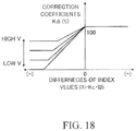
- FIG. 18 is a map showing a relationships between differences I 1 i ⁇ Kc ⁇ I 2 i between the index value I 1 i indicating the degree of floating vibrations and the product of the index value I 2 i indicating the degree of rugged vibrations and the correction coefficient Kc, and the correction coefficients Kdi.
- a damping force control device 10 is adapted to a vehicle 14 having right and left front wheels 12 FL and 12 FR which are steered wheels and left and right rear wheels 12 RL and 12 RR which are non-steered wheels.
- the left and right front wheels 12 FL and 12 FR are suspended from a vehicle body 18 by suspensions 16 FL and 16 FR, respectively, and the left and right rear wheels 12 RL and 12 RR are suspended from the vehicle body 18 by suspensions 16 RL and 16 RR, respectively.
- the suspensions 16 FL to 16 RR include shock absorbers 20 FL to 20 RR and suspension springs 22 FL to 22 RR, respectively.
- the wheels 12 FL to 12 RR are rotatably supported by wheel carriers 24 FL to 24 RR, respectively, and the wheel carriers 24 FL to 24 RR are each connected to the vehicle body 18 by a suspension arm, not shown, so as to be mainly displaceable in the vertical direction with respect to the vehicle body 18 .
- the shock absorbers 20 FL to 20 RR are mounted between the vehicle body 18 and the wheel carriers 24 FL to 24 RR or the suspension arms, respectively, and extend substantially in the vertical direction.
- the vehicle body 18 can be displaced with respect to the wheels 12 FL to 12 RR at least in the vertical direction as the shock absorbers 20 FL to 20 RR and the suspension springs 22 FL to 22 RR expand and contract at the positions of the wheels 12 FL to 12 RR. Therefore, the vehicle body 18 , parts of the shock absorbers 20 FL to 20 RR, parts of the suspension arms, and the like constitute the sprung mass of the vehicle 14 .
- the wheels 12 FL to 12 RR, the wheel carriers 24 FL to 24 RR, the other parts of the shock absorbers 20 FL to 20 RR, the other parts of the suspension arms, and the like constitute the unsprung masses of the vehicle.
- the suspension springs 22 FL to 22 RR suppress the vertical displacements of the wheels 12 FL to 12 RR caused by the vertical fluctuation of a road surface and impacts received by the wheels 12 FL to 12 RR from the road surface and the like from being transmitted to the sprung mass.
- the shock absorbers 20 FL to 20 RR generate damping forces for damping vibrations caused by relative displacements of the sprung and unsprung masses in the vertical direction.
- the shock absorbers 20 FL to 20 RR are damping force variable shock absorbers having actuators 26 FL to 26 RR, respectively, that change the opening amounts of built-in damping force generating valves.
- the shock absorbers 20 FL to 20 RR have a plurality of control stages S.
- the actuators 26 FL to 26 RR are controlled by an electronic control unit 28 .
- the vehicle body 18 is provided at positions corresponding to the wheels 12 FL to 12 RR with vertical acceleration sensors 30 FL to 30 RR that detect corresponding vertical accelerations GzFL to GzRR, respectively. Signals indicating the detected vertical accelerations GzFL to GzRR are input to the electronic control unit 28 . Only three vertical acceleration sensors may be provided and a vertical acceleration of the vehicle body 18 at the position where no vertical acceleration sensor is provided may be estimated in a known manner based on the three vertical accelerations detected by the three vertical acceleration sensors.
- the electronic control unit 28 controls the damping forces Fi of the shock absorbers 20 FL to 20 RR according to a control program corresponding to the flowcharts shown in FIGS. 2 to 4 .
- the electronic control unit 28 may be a microcomputer having, for example, a CPU, a ROM, a RAM, and an input/output port device, which are mutually connected by a bidirectional common bus.
- the control program is stored in the ROM, and the damping forces Fi are controlled by the CPU according to the control program.
- control the damping force control routine in the first embodiment will be described with reference to the flowchart shown in FIG. 2 . It is to be noted that the control according to the flowchart shown in FIG. 2 is repeatedly executed at predetermined time intervals sequentially for the left front wheel, the right front wheel, the left rear wheel, and the right rear wheel every prescribed period of time when an ignition switch (not shown) is ON. In the following description, the control of the damping forces executed according to the flowchart is simply referred to as “control”.
- step 10 signals indicative of the vertical accelerations GzFL to GzRR detected by the vertical acceleration sensors 30 FL to 30 RR are read.
- Csf in the following formula (1) is a damping coefficient of the Skyhook control, but may be any damping coefficient of an arbitrary damping force control (for example, H ⁇ control) that damps a vibration of the vehicle body 18 to improve the ride comfort of the vehicle 14 .
- Fti Csf ⁇ Vrei (1)
- the floating vibration is a vibration in a frequency range in which an occupant of the vehicle 14 feels a loose feeling of the vehicle body 18 .
- the vibration is a vibration of 1 to 2 Hz which is a resonance frequency range of the vehicle body 18 as a sprung mass.
- index values I 2 i indicating the degree of the rugged vibration as the second vibration (hereinafter referred to simply as “index values of rugged vibration”) are calculated based on the vertical accelerations GzFL to GzRR.
- the rugged vibration is a vibration in a frequency range in which an occupant of the vehicle 14 feels an undesirable rugged feeling.
- the vibration is a vibration in the frequency range of 6 to 10 Hz which is between a resonance frequency range of the vehicle body 18 as a sprung mass and a resonance frequency range of wheels 12 FL to 12 RR, the wheel carriers 24 FL to 24 RR and the like as unsprung masses.
- the lower limit frequency may be lower than 6 Hz as long as it is higher than a resonance frequency range of the unsprung masses.
- the ratios I 2 i /I 1 i are calculated after the index values I 1 i are set to a positive constant close to 0 which is set in advance.
- step 70 the correction coefficients Kri are corrected by a low-pass filter so that the rates of change of the correction coefficients Kri are limited.
- the rates of change of the correction coefficients Kri may be limited by the means in which the magnitude of the change amount of the correction coefficients per unit time is guard processed; the correction coefficients are subjected to moving average processing; the correction coefficients are held at a constant value for a predetermined holding time, or the like. This also applies to correction coefficients in other embodiments described later.
- Ffti Kri ⁇ Fti (2)
- step 220 control of the damping forces is executed by controlling the control stages of the shock absorbers 20 FL to 20 RR so that the control stages become the target control stages S calculated in step 210 . Therefore, by controlling the damping coefficients Ci of the shock absorbers 20 FL to 20 RR to the target damping coefficients Cti, the damping forces Fi are controlled to be the final target damping forces Ffti.
- the frequency range of 0.5 to 2 Hz is an example, and the frequency range of the components of the first vibration may be different from the exemplified frequency range.
- step 44 the signals indicating the floating components are subjected to full-wave rectification so that the floating components are converted into absolute values. That is, negative values of the floating component signals are converted into positive values with the same absolute values.
- step 46 the maximum values of the floating components that are converted into the absolute values within the preset time Tc (positive constant) up to the present are calculated as the index values I 1 i of the floating vibrations.
- the frequency range of 4 to 10 Hz is an example, and the frequency range of the components of the second vibration may be different from the exemplified frequency range.
- step 54 the signals of the rugged components are full-wave rectified so that the rugged components are converted into absolute values. That is, negative values of the rugged component signals are converted into positive values with the same absolute values.
- step 56 the signals of the rugged components converted to the absolute values are processed by a low-pass filter having a cutoff frequency (for example 2 Hz) for removing high frequency noises, whereby the noises having frequencies higher than the frequencies of the rugged components are removed.
- a cutoff frequency for example 2 Hz
- step 58 the maximum values of the rugged components which were converted into the absolute values within the preset time Tc up to the present and whose noises are removed are calculated as the index values I 2 i of the rugged vibrations.
- step 20 vertical relative speeds Vrei between the wheels 12 FL to 12 RR and the vehicle body 18 are calculated based on the vertical accelerations GzFL to GzRR, and in step 30 , target damping forces Fti of the shock absorbers 20 FL to 20 RR are calculated based on the vertical relative speeds Vrei.
- steps 40 and 50 index values I 1 i of the floating vibration and index values I 2 i of the rugged vibration are calculated based on the vertical accelerations GzFL to GzRR.
- step 60 correction coefficients Kri are calculated based on the ratio I 2 i /I 1 i of the index values I 2 i of the rugged vibration to the index values I 1 i of the floating vibration.
- the correction coefficients Kri decrease as the ratios I 2 i /I 1 i increase and increase as a vehicle speed V increases.
- step 70 the correction coefficients Kri are corrected so that the rates of change are limited.
- step 80 final target damping forces Ffti are calculated as the products of the corrected correction coefficients Kri and the vertical relative speeds Vrei, and in steps 210 and 220 , damping forces Fi of the shock absorbers 20 FL to 20 RR are controlled to the final target damping forces Ffti.
- the second embodiment is configured as a modification example of the first embodiment, and the damping force control in the second embodiment is performed according to the flowchart shown in FIG. 5 .
- FIG. 5 the same step numbers as those shown in FIG. 2 are assigned to the same steps as those shown in FIG. 2 . This also applies to other embodiments to be described later.
- the second embodiment is configured as a modification example of the first embodiment, and steps 10 to 50 and steps 210 and 220 are executed in the same manners as in the first embodiment. In place of steps 60 to 80 in the first embodiment, steps 90 to 110 are executed, respectively.
- step 100 the correction coefficients Kdi are corrected by low-pass filtering so that the rates of change are limited.
- step 110 final target damping forces Ffti of the shock absorbers 20 FL to 20 RR are calculated using the corrected correction coefficients Kdi according to the following formula (3).
- Ffti Kdi ⁇ Fti (3) [Third Embodiment]
- the third embodiment is also configured as a modification example of the first embodiment, and the damping force control in the third embodiment is performed alternately for the front two wheels and the rear two wheels, for example, according to the flowchart shown in FIG. 6 .
- Steps 10 to 50 and steps 210 and 220 are executed in the same manners as in the first embodiment.
- steps 120 to 140 are executed, respectively.
- the larger one of the index values I 1 FL and I 1 FR of the floating vibration is set as the index value I 1 fr of the floating vibration of the vehicle body 18 at the positions corresponding to the front wheels 12 FL and 12 FR.
- the larger one of the index values I 1 RL and I 1 RR of the floating vibration is set as the index value I 1 re of the floating vibration of the vehicle body 18 at the positions corresponding to the rear wheels 12 RL and 12 RR.
- the larger one of the index values I 2 FL and I 2 FR of the rugged vibration is set as the index value I 2 fr of the rugged vibration of the vehicle body 18 at the positions corresponding to the front wheels 12 FL and 12 FR.
- the larger one of the index values I 2 RL and I 2 RR of the rugged vibration is set as the index value I 2 re of the rugged vibration of the vehicle body 18 at the positions corresponding to the rear wheels 12 RL and 12 RR.
- step 120 the ratios I 2 fr /I 1 fr and I 2 re /I 1 re of the index values I 2 fr and I 2 re of the rugged vibration to the index values I 1 fr and I 1 re of the floating vibrations are calculated, respectively. Furthermore, correction coefficients Krfr and Krre for the front two wheels and the rear two wheels are calculated by referring to the map shown in FIG. 12 based on the ratios I 2 fr /I 1 fr and I 2 re /I 1 re , respectively.
- step 130 the correction coefficients Krfr and Krre are corrected by low-pass filtering so that the rates of change are limited.
- step 140 final target damping forces Ffti of the shock absorbers 20 FL to 20 RR are calculated according to the following formulas (4) to (7) using the corrected correction coefficients Krfr and Krre.
- FftFL Krfr ⁇ FtFL (4)
- FftFR Krfr ⁇ FtFR (5)
- FftRL Krre ⁇ FtRL (6)
- FftRR Krre ⁇ FtRR (7) [Fourth Embodiment]
- the fourth embodiment is configured as a modification example of the third embodiment, and the damping force control in the fourth embodiment is performed alternately for the front two wheels and the rear two wheels, for example, according to the flowchart shown in FIG. 7 .
- Steps 10 to 50 and steps 210 and 220 are executed in the same manners as in the third embodiment.
- Steps 150 to 170 are executed in place of steps 120 to 140 , respectively, in the third embodiment.
- step 150 as in step 120 in the third embodiment, index value I 1 fr of the floating vibration and index value I 2 fr of the rugged vibration of the vehicle body 18 at the positions corresponding to the front wheels 12 FL and 12 FR are calculated. Similarly, index value I 1 re of the floating vibration and index value I 2 re of the rugged vibration of the vehicle body 18 at the positions corresponding to the rear wheels 12 RL and 12 RR are calculated.
- step 150 similarly to step 90 in the second embodiment, difference Kc ⁇ I 2 fr ⁇ I 1 fr between the product of the index value I 2 fr of the rugged vibration and the correction coefficient Kc and the index value I 1 fr of the floating vibration are calculated and difference Kc ⁇ I 2 re ⁇ I 1 re between the product of the index value I 2 re of the rugged vibration and the correction coefficient Kc and the index value I 1 re of the floating vibration are calculated. Furthermore, correction coefficients Kdfr and Kdre for the front two wheels and the rear two wheels are calculated by referring to the map shown in FIG. 13 based on the differences Kc ⁇ I 2 fr ⁇ I 1 fr and Kc ⁇ I 2 re ⁇ I 1 re , respectively.
- step 160 the correction coefficients Kdfr and Kdre are corrected by low-pass filtering so that the rates of change are limited.
- step 170 final target damping forces Ffti of the shock absorbers 20 FL to 20 RR are calculated according to the following formulas (8) to (11) using the corrected correction coefficients Kdfr and Kdre.
- FftFL Kdfr ⁇ FtFL (8)
- FftFR Kdfr ⁇ FtFR (9)
- FftRL Kdre ⁇ FtRL (10)
- FftRR Kdre ⁇ FtRR (11) [Fifth Embodiment]
- the fifth embodiment is configured as a modification example of the first embodiment, and the damping force control in the fifth embodiment is the same as the first embodiment except that the damping force control is performed alternately for the two left wheels and the two right wheels according to the flowchart shown in FIG. 8 .
- Steps 10 to 50 and steps 210 and 220 are executed in the same manners as in the first embodiment.
- steps 125 to 145 are executed, respectively.
- the larger one of the index values I 1 FL and I 1 RL of the floating vibration is set as the index value I 1 lt of the floating vibration of the vehicle body 18 at the positions corresponding to the two left wheels 12 FL and 12 RL.
- the larger one of the index values I 1 FR and I 1 RR of the floating vibration is set as the index value I 1 rt of the floating vibration of the vehicle body 18 at the positions corresponding to the two right wheels 12 FR and 12 RR.
- the larger one of the index values I 2 FL and I 2 RL of the rugged vibration is set as the index value I 2 flt of the rugged vibration of the vehicle body 18 at the positions corresponding to the two left wheels 12 FL and 12 RL.
- the larger one of the index values I 2 FR and I 2 R R of the rugged vibration is set as the index value I 2 rt of the rugged vibration of the vehicle body 18 at the positions corresponding to the two right wheels 12 FR and 12 RR.
- step 125 ratios I 2 lt /I 1 lt and I 2 rt /I 1 rt of the index values I 2 lt and I 2 rt of the rugged vibration to the index values I 1 lt and I 1 rt of the floating vibrations are calculated, respectively. Further, correction coefficients Krit and Krrt for the two left wheels and the two right wheels are calculated by referring to the map shown in FIG. 14 based on the ratios I 2 lt /I 1 lt and I 2 rt /I 1 rt.
- step 135 the correction coefficients Krlt and Krrt are corrected by low-pass filtering so that the rates of change are limited.
- step 145 final target damping forces Ffti of the shock absorbers 20 FL to 20 RR are calculated according to the following formulas (12) to (15) using the corrected correction coefficients Krlt and Krrt.
- FftFL Krlt ⁇ FtFL (12)
- FftFR Krrt ⁇ FtFR (13)
- FftRL Krlt ⁇ FtRL (14)
- FftRR Krrt ⁇ FtRR (15) [Sixth Embodiment]
- the sixth embodiment is configured as a modification example of the fourth embodiment, and the damping force control in the sixth embodiment is performed for the two left wheels and the two right wheels, for example, according to the flowchart shown in FIG. 9 .
- Steps 10 to 50 and steps 210 and 220 are executed in the same manners as in the fourth embodiment.
- steps 155 to 175 are executed, respectively.
- step 155 similarly to step 150 in the fourth embodiment, index value I 1 lt of the floating vibration and index value I 2 lt of the rugged vibration of the vehicle body 18 at the positions corresponding to the two left wheels 12 FL and 12 RL are calculated. Similarly, index value I 1 rt of the floating vibration and index value I 2 rt of the rugged vibration of the vehicle body 18 at positions corresponding to the two right wheels 12 FR and 12 RR are calculated.
- step 155 similarly to step 150 in the second embodiment, a difference Kc ⁇ I 2 lt ⁇ I 1 lt between the product of the index value I 2 lt of the rugged vibration and the correction coefficient Kc and the index value I 1 lt of the floating vibration is calculated.
- a difference Kc ⁇ I 2 rt ⁇ I 1 rt between the product of the index value I 2 rt of the rugged vibration and the correction coefficient Kc and the index value I 1 rt of the floating vibration is calculated.
- correction coefficients Kdlt and Kdrt for the left two wheels and the right two wheels are calculated by referring to the map shown in FIG. 15 based on the differences Kc ⁇ I 2 lt ⁇ I 1 lt and Kc ⁇ I 2 rt ⁇ I 1 rt , respectively.
- step 165 the correction coefficients Kdlt and Kdrt are corrected by low-pass filtering so that the rates of change are limited.
- step 175 final target damping forces Ffti of the shock absorbers 20 FL to 20 RR are calculated according to the following formulas (16) to (19) using the corrected correction coefficients Kdlt and Kdrt.
- FftFL Kdlt ⁇ FtFL (16)
- FftFR Kdrt ⁇ FtFR (17)
- FftRL Kdlt ⁇ FtRL (18)
- FftRR Kdrt ⁇ FtRR (19)
- the correction coefficients such as Kri are calculated such that the larger the magnitudes of the index values I 2 i of the rugged vibration is relative to the magnitudes of the index values I 1 i of the floating vibration, in other words, the higher the degree of the rugged vibration is relative to the degree of the floating vibration, the smaller the correction coefficients are.
- the damping coefficients Ci of the shock absorbers 20 FL to 20 RR are controlled so that the damping forces Fi of the shock absorbers become the final target damping forces Ffti which are the products of the target damping forces Fti and the correction coefficients, that is, the target damping forces corrected by the correction coefficients.
- the damping forces of the shock absorbers 20 FL to 20 RR can be controlled in accordance with the relationship between the degree of the floating vibration components and the degree of the rugged vibration components so that the higher the degree of the rugged vibration components is relative to the degree of the floating vibration components, the smaller the damping forces are. Accordingly, when the degree of the rugged vibration components is low with respect to the degree of the floating vibration components, it is possible to prevent the damping forces of the shock absorbers from decreasing and to effectively attenuate the vibrations of the floating components.
- the maps used for calculation of the correction coefficients such as Kri are one-dimensional maps having variable parameters of the ratios or the differences between the index values I 1 i of the floating vibration and the index values of the rugged vibration.
- two-dimensional maps showing the relationships among the index values I 1 i of the floating vibration, the index values I 2 i of the rugged vibration and the correction coefficients are unnecessary. Therefore, it is not necessary to create maps by taking a lot of time and effort to determine necessary values experimentally, for example.
- the correction coefficients such as Kri are variably set according to a vehicle speed V so that the correction coefficients increase as a vehicle speed increases. Consequently, the damping forces can be increased as a vehicle speed increases. Therefore, when a vehicle speed is low, it is possible to prevent the damping forces from becoming excessive to ensure good ride comfort of the vehicle, while on the other hand, when a vehicle speed is high, sufficient damping forces are generated to ensure good driving stability of the vehicle.
- the rates of change of the correction coefficients such as Kri are limited in step 70 or the like. It is possible to reduce the possibility that the damping forces of the shock absorbers suddenly change due to sudden changes in the correction coefficients in accordance with the fluctuation of the index values I 1 i of the floating vibration and the index values I 2 i of the rugged vibration.
- the number of correction coefficients is two, as compared with the first and second embodiments in which four correction coefficients are calculated for the wheels, it is possible to reduce calculation load of the electronic control unit 28 and to reduce the possibility of delay in controlling the damping forces of the shock absorbers.
- the index values I 1 i of the floating vibration and the index values I 2 i of the rugged vibration are the maximum values of absolute values of the floating components Gz 1 i and the rugged components Gz 2 i , respectively, within the time period Tc.
- the index values I 1 i and I 2 i may be arbitrary values indicating the degree of floating vibrations and the degree of rugged vibrations, respectively, such as the integral values of the converted absolute values within the time period Tc or the integral values of the values exceeding a reference value out of the converted absolute values within the time period Tc.
- the correction coefficients such as Kri have linear relationships with the ratio of the index values.
- the correction coefficients are smaller when the ratio of the index values is large than those when the ratio of the index values is small, and the correction coefficients may be, for example, nonlinear, stepwise or the like with respect to the ratio of the index values.
- the correction coefficients such as Kdi have linear relationships with the differences of the index values.
- the correction coefficients may be smaller when the differences between the index values are large than those when the differences between the index values are small, and the correction coefficients may be, for example, nonlinear, stepwise or the like with respect to the differences between the index values.
- the parameters for calculating the correction coefficients such as Kri are the ratio of the index values of the rugged vibration to the index values of the floating vibration.
- the same parameters may be ratios (for example, I 1 i /I 2 i ) of the index values of the floating vibration to the index values of the rugged vibration.
- the smaller the ratios of the index values of the floating vibration to the index values of the rugged vibration the larger the ratios of the index values of the rugged vibration to the index values of the floating vibration. Therefore, as shown in FIG. 17 for the correction coefficients Kri, for example, the maps for calculating the correction coefficients are opposite in right and left to the maps ( FIGS. 10, 12 and 14 ) in the illustrated embodiments.
- the parameters for calculating the correction coefficients such as Kdi are the differences between the products of the index values of the rugged vibration and the correction coefficient Kc and the index values of the floating vibration.
- the same parameters may be the differences (for example, I 1 i ⁇ Kc ⁇ I 2 i ) between the index values of the floating vibration and the products of the index values of the rugged vibration and the correction coefficient Kc.
- the smaller the differences the larger the absolute values of the differences that are negative values
- the correction coefficients such as Kri are variably set in accordance with a vehicle speed V so that the coefficients increase as a vehicle speed increases.
- the embodiments may be modified such that the correction coefficients are calculated using a map not dependent on a vehicle speed, and the correction coefficients are multiplied by a correction coefficient which increases as a vehicle speed V increases. Further, the correction coefficients may be calculated to values independent of a vehicle speed.
- the corrections of the index values I 2 i of the rugged vibration by the correction coefficient Kc that are executed in the second, fourth and sixth embodiments are not executed, but the index values I 2 i of rugged vibration may be corrected by the correction coefficient Kc.
Landscapes
- Engineering & Computer Science (AREA)
- Mechanical Engineering (AREA)
- Vehicle Body Suspensions (AREA)
Abstract
Description
Fti=Csf·Vrei (1)
Ffti=Kri·Fti (2)
Ffti=Kdi·Fti (3)
[Third Embodiment]
FftFL=Krfr·FtFL (4)
FftFR=Krfr·FtFR (5)
FftRL=Krre·FtRL (6)
FftRR=Krre·FtRR (7)
[Fourth Embodiment]
FftFL=Kdfr·FtFL (8)
FftFR=Kdfr·FtFR (9)
FftRL=Kdre·FtRL (10)
FftRR=Kdre·FtRR (11)
[Fifth Embodiment]
FftFL=Krlt·FtFL (12)
FftFR=Krrt·FtFR (13)
FftRL=Krlt·FtRL (14)
FftRR=Krrt·FtRR (15)
[Sixth Embodiment]
FftFL=Kdlt·FtFL (16)
FftFR=Kdrt·FtFR (17)
FftRL=Kdlt·FtRL (18)
FftRR=Kdrt·FtRR (19)
Claims (4)
Applications Claiming Priority (2)
| Application Number | Priority Date | Filing Date | Title |
|---|---|---|---|
| JP2016-096906 | 2016-05-13 | ||
| JP2016096906A JP6478063B2 (en) | 2016-05-13 | 2016-05-13 | Damping force control device for vehicle |
Publications (2)
| Publication Number | Publication Date |
|---|---|
| US20170326936A1 US20170326936A1 (en) | 2017-11-16 |
| US10538136B2 true US10538136B2 (en) | 2020-01-21 |
Family
ID=60294429
Family Applications (1)
| Application Number | Title | Priority Date | Filing Date |
|---|---|---|---|
| US15/593,944 Expired - Fee Related US10538136B2 (en) | 2016-05-13 | 2017-05-12 | Damping force control device for vehicle |
Country Status (3)
| Country | Link |
|---|---|
| US (1) | US10538136B2 (en) |
| JP (1) | JP6478063B2 (en) |
| CN (1) | CN107399216B (en) |
Cited By (1)
| Publication number | Priority date | Publication date | Assignee | Title |
|---|---|---|---|---|
| US11529837B2 (en) * | 2017-01-05 | 2022-12-20 | Mclaren Automotive Limited | Damper control |
Families Citing this family (8)
| Publication number | Priority date | Publication date | Assignee | Title |
|---|---|---|---|---|
| JP7059791B2 (en) * | 2018-05-16 | 2022-04-26 | トヨタ自動車株式会社 | Damping force control device |
| CN113557148B (en) * | 2019-03-25 | 2022-10-14 | 日产自动车株式会社 | Suspension control method and suspension control system |
| US12128726B2 (en) * | 2021-01-28 | 2024-10-29 | Volvo Car Corporation | Rear damper adjustment |
| DE102021131065A1 (en) * | 2021-11-26 | 2023-06-01 | Audi Aktiengesellschaft | Active chassis control for a motor vehicle |
| CN114312202B (en) * | 2022-03-10 | 2022-06-03 | 成都九鼎科技(集团)有限公司 | Semi-active suspension control method and system based on road condition recognition |
| KR20230138097A (en) * | 2022-03-23 | 2023-10-05 | 현대자동차주식회사 | Method for controlling driving force of vehicle |
| KR20230138564A (en) * | 2022-03-23 | 2023-10-05 | 현대자동차주식회사 | Method for controlling driving force of vehicle |
| US20250360768A1 (en) * | 2024-05-21 | 2025-11-27 | Magna International Inc. | Vehicle motion control system and method |
Citations (4)
| Publication number | Priority date | Publication date | Assignee | Title |
|---|---|---|---|---|
| JPH06143965A (en) | 1992-01-14 | 1994-05-24 | Nippondenso Co Ltd | Damping force control device for shock absorber of vehicle |
| US5322320A (en) | 1992-01-14 | 1994-06-21 | Nippondenso Co., Ltd. | Shock absorber damping force control system for vehicle |
| US5444621A (en) * | 1991-06-10 | 1995-08-22 | Nippondenso Co., Ltd. | Suspension control system for controlling suspension of automotive vehicle based on wheel speed data |
| JPH08216646A (en) | 1995-02-17 | 1996-08-27 | Nippondenso Co Ltd | Damping force control device for suspension |
Family Cites Families (4)
| Publication number | Priority date | Publication date | Assignee | Title |
|---|---|---|---|---|
| GB8610842D0 (en) * | 1986-05-02 | 1986-06-11 | Bl Tech Ltd | Suspension system |
| JPH05229329A (en) * | 1992-02-14 | 1993-09-07 | Mitsubishi Motors Corp | Damping force control method of car suspension |
| JPH0858338A (en) * | 1994-08-25 | 1996-03-05 | Nippondenso Co Ltd | Vehicle damping force control device |
| JPH08230432A (en) * | 1995-02-23 | 1996-09-10 | Toyota Motor Corp | Vehicle damping force control device |
-
2016
- 2016-05-13 JP JP2016096906A patent/JP6478063B2/en not_active Expired - Fee Related
-
2017
- 2017-05-12 US US15/593,944 patent/US10538136B2/en not_active Expired - Fee Related
- 2017-05-12 CN CN201710338503.3A patent/CN107399216B/en not_active Expired - Fee Related
Patent Citations (4)
| Publication number | Priority date | Publication date | Assignee | Title |
|---|---|---|---|---|
| US5444621A (en) * | 1991-06-10 | 1995-08-22 | Nippondenso Co., Ltd. | Suspension control system for controlling suspension of automotive vehicle based on wheel speed data |
| JPH06143965A (en) | 1992-01-14 | 1994-05-24 | Nippondenso Co Ltd | Damping force control device for shock absorber of vehicle |
| US5322320A (en) | 1992-01-14 | 1994-06-21 | Nippondenso Co., Ltd. | Shock absorber damping force control system for vehicle |
| JPH08216646A (en) | 1995-02-17 | 1996-08-27 | Nippondenso Co Ltd | Damping force control device for suspension |
Cited By (1)
| Publication number | Priority date | Publication date | Assignee | Title |
|---|---|---|---|---|
| US11529837B2 (en) * | 2017-01-05 | 2022-12-20 | Mclaren Automotive Limited | Damper control |
Also Published As
| Publication number | Publication date |
|---|---|
| JP6478063B2 (en) | 2019-03-06 |
| US20170326936A1 (en) | 2017-11-16 |
| CN107399216A (en) | 2017-11-28 |
| CN107399216B (en) | 2019-09-24 |
| JP2017202789A (en) | 2017-11-16 |
Similar Documents
| Publication | Publication Date | Title |
|---|---|---|
| US10538136B2 (en) | Damping force control device for vehicle | |
| US11203244B2 (en) | Damping control apparatus for vehicle | |
| US9375990B2 (en) | Suspension control device | |
| US9061562B2 (en) | Suspension control apparatus | |
| US10703162B2 (en) | Suspension control system | |
| EP2537691B1 (en) | Damping force control device for vehicle | |
| JP6607229B2 (en) | Vehicle attitude control device | |
| CN102131663A (en) | Method and apparatus for controlling a semi-active suspension system of a motorcycle | |
| JPH0648133A (en) | Vehicle suspension | |
| KR102776220B1 (en) | Apparatus and method for controlling damping force through road frequency classification | |
| WO2016006443A1 (en) | Signal processing device, suspension control device, and signal processing method | |
| CN116001510A (en) | Vehicle suspension control device and vehicle suspension control method | |
| US5328202A (en) | Apparatus for controlling damping coefficient for vehicular shock absorber | |
| JP5664569B2 (en) | Vehicle suspension system | |
| JP3342622B2 (en) | Loading status judgment device | |
| KR100831895B1 (en) | Control Method of Semi-active Suspension for Vehicle | |
| GB2282784A (en) | Vehicle suspension system | |
| JP2013154821A (en) | Vehicle suspension system | |
| CN121175204A (en) | Attenuation force control device | |
| CN119836355A (en) | Control device | |
| JP2009137342A (en) | Control device for damping force variable damper | |
| CN113983981A (en) | Method for acquiring sprung and unsprung displacements of damping continuously adjustable shock absorber | |
| JPH0920118A (en) | Vehicle suspension | |
| JPH08216647A (en) | Vehicle suspension | |
| KR20080044572A (en) | How to calculate the vertical velocity of the car body using the height sensor |
Legal Events
| Date | Code | Title | Description |
|---|---|---|---|
| AS | Assignment |
Owner name: TOYOTA JIDOSHA KABUSHIKI KAISHA, JAPAN Free format text: ASSIGNMENT OF ASSIGNORS INTEREST;ASSIGNOR:SAITO, TAKASHI;REEL/FRAME:042357/0749 Effective date: 20170411 |
|
| STPP | Information on status: patent application and granting procedure in general |
Free format text: NON FINAL ACTION MAILED |
|
| STPP | Information on status: patent application and granting procedure in general |
Free format text: RESPONSE TO NON-FINAL OFFICE ACTION ENTERED AND FORWARDED TO EXAMINER |
|
| STPP | Information on status: patent application and granting procedure in general |
Free format text: NOTICE OF ALLOWANCE MAILED -- APPLICATION RECEIVED IN OFFICE OF PUBLICATIONS |
|
| STPP | Information on status: patent application and granting procedure in general |
Free format text: PUBLICATIONS -- ISSUE FEE PAYMENT RECEIVED |
|
| STCF | Information on status: patent grant |
Free format text: PATENTED CASE |
|
| FEPP | Fee payment procedure |
Free format text: MAINTENANCE FEE REMINDER MAILED (ORIGINAL EVENT CODE: REM.); ENTITY STATUS OF PATENT OWNER: LARGE ENTITY |
|
| LAPS | Lapse for failure to pay maintenance fees |
Free format text: PATENT EXPIRED FOR FAILURE TO PAY MAINTENANCE FEES (ORIGINAL EVENT CODE: EXP.); ENTITY STATUS OF PATENT OWNER: LARGE ENTITY |
|
| STCH | Information on status: patent discontinuation |
Free format text: PATENT EXPIRED DUE TO NONPAYMENT OF MAINTENANCE FEES UNDER 37 CFR 1.362 |
|
| FP | Lapsed due to failure to pay maintenance fee |
Effective date: 20240121 |