US10537229B2 - Introduction device - Google Patents
Introduction device Download PDFInfo
- Publication number
- US10537229B2 US10537229B2 US15/042,537 US201615042537A US10537229B2 US 10537229 B2 US10537229 B2 US 10537229B2 US 201615042537 A US201615042537 A US 201615042537A US 10537229 B2 US10537229 B2 US 10537229B2
- Authority
- US
- United States
- Prior art keywords
- rotary body
- shaft portion
- bending
- main body
- bending section
- Prior art date
- Legal status (The legal status is an assumption and is not a legal conclusion. Google has not performed a legal analysis and makes no representation as to the accuracy of the status listed.)
- Active
Links
Images


Classifications
-
- A—HUMAN NECESSITIES
- A61—MEDICAL OR VETERINARY SCIENCE; HYGIENE
- A61B—DIAGNOSIS; SURGERY; IDENTIFICATION
- A61B1/00—Instruments for performing medical examinations of the interior of cavities or tubes of the body by visual or photographical inspection, e.g. endoscopes; Illuminating arrangements therefor
- A61B1/005—Flexible endoscopes
- A61B1/0051—Flexible endoscopes with controlled bending of insertion part
- A61B1/0052—Constructional details of control elements, e.g. handles
-
- A—HUMAN NECESSITIES
- A61—MEDICAL OR VETERINARY SCIENCE; HYGIENE
- A61B—DIAGNOSIS; SURGERY; IDENTIFICATION
- A61B1/00—Instruments for performing medical examinations of the interior of cavities or tubes of the body by visual or photographical inspection, e.g. endoscopes; Illuminating arrangements therefor
- A61B1/00002—Operational features of endoscopes
- A61B1/00039—Operational features of endoscopes provided with input arrangements for the user
- A61B1/00042—Operational features of endoscopes provided with input arrangements for the user for mechanical operation
-
- G—PHYSICS
- G02—OPTICS
- G02B—OPTICAL ELEMENTS, SYSTEMS OR APPARATUS
- G02B23/00—Telescopes, e.g. binoculars; Periscopes; Instruments for viewing the inside of hollow bodies; Viewfinders; Optical aiming or sighting devices
- G02B23/24—Instruments or systems for viewing the inside of hollow bodies, e.g. fibrescopes
- G02B23/2476—Non-optical details, e.g. housings, mountings, supports
Definitions
- the present invention relates to an introduction device which is inserted into a cavity.
- an introduction device for introduction into a cavity such as an endoscope
- an insertion section with flexibility which is inserted into a subject in order to observe, treat, etc. a diseased part in the subject
- the operation section includes a UD angle knob for performing an operation in the UD direction, and an RL angle knob for performing an operation in the RL direction.
- bending of the insertion section in the up-and-down (UD) direction is performed by a manual operation, and bending in the right-and-left (RL) direction is automatically operated by driving of a motor.
- the operation section includes a knob for an operation in the up-and-down (UD) direction, and a dial for an operation in the right-and-left (RL) direction.
- an introduction device includes an operation main body provided with a first surface; a grip section neighboring the operation main body and provided along a longitudinal axis; a bending section capable of bending in a first direction and a second direction crossing the first direction; a first rotary body configured to be rotatable about a first shaft portion projecting from the first surface, and to be operated at a time of bending the bending section in the first direction; and a second rotary body configured to be rotatable about a second shaft portion projecting from the operation main body, and to be operated at a time of bending the bending section in the second direction, the second rotary body being configured such that a part of an outer edge, which part is located on a distal-end direction side of the first shaft portion, is located on an extension plane which is defined by extending the first surface, or the part of the outer edge, which part is located on the distal-end direction side of the first shaft portion, is located more on the distal-end direction
- FIG. 1 is a perspective view illustrating the entire structure of an endoscope device of a first embodiment.
- FIG. 2 is a front view illustrating, from an end face side, a distal rigid section of the endoscope device shown in FIG. 1 .
- FIG. 3 is a cross-sectional view illustrating bend pieces, first wires and second wires, which are disposed within a bending section of the endoscope device shown in FIG. 1 .
- FIG. 4 is a cross-sectional view taken along line F 4 -F 4 in FIG. 3 .
- FIG. 5 is a front view illustrating, from a first surface side (front-surface side), an operation main body of the endoscope device shown in FIG. 1 .
- FIG. 6 is a side view illustrating, from a proximal-end direction, the operation main body of the endoscope device shown in FIG. 5 .
- FIG. 7 is a side view illustrating, from a second surface side (side-surface side), the operation main body of the endoscope device shown in FIG. 5 .
- FIG. 8 is a cross-sectional view, taken along line F 8 -F 8 in FIG. 7 , illustrating an endoscope of the endoscope device shown in FIG. 7 .
- FIG. 9 is a cross-sectional view illustrating the position of a left middle finger before movement at a time when a second rotary body of the endoscope shown in FIG. 8 is rotated clockwise.
- FIG. 10 is a cross-sectional view illustrating the position of the left middle finger after movement at a time when the second rotary body of the endoscope shown in FIG. 9 is rotated clockwise.
- FIG. 11 is a cross-sectional view illustrating the position of the left middle finger before movement at a time when the second rotary body of the endoscope shown in FIG. 8 is rotated counterclockwise.
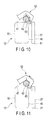
- FIG. 12 is a cross-sectional view illustrating the position of the left middle finger after movement at a time when the second rotary body of the endoscope shown in FIG. 8 is rotated counterclockwise.
- FIG. 13 is a cross-sectional view illustrating the position of the second rotary body, FIG. 13 being a cross-sectional view in which an endoscope of an endoscope device of a second embodiment is cut along a plane perpendicular to the longitudinal axis.
- FIG. 14 is a cross-sectional view illustrating the position of the second rotary body, FIG. 14 being a cross-sectional view in which an endoscope of an endoscope device of a third embodiment is cut along a plane perpendicular to the longitudinal axis.
- FIG. 15 is a cross-sectional view illustrating the position of the second rotary body, FIG. 15 being a cross-sectional view in which an endoscope of an endoscope device of a fourth embodiment is cut along a plane perpendicular to the longitudinal axis.
- FIG. 16 is a cross-sectional view illustrating the position of the second rotary body, FIG. 16 being a cross-sectional view in which an endoscope of an endoscope device of a fifth embodiment is cut along a plane perpendicular to the longitudinal axis.
- FIG. 17 is a cross-sectional view illustrating the position of the second rotary body, FIG. 17 being a cross-sectional view in which an endoscope of an endoscope device of a sixth embodiment is cut along a plane perpendicular to the longitudinal axis.
- FIG. 18 is a perspective view illustrating an endoscope device of a modification of the first to sixth embodiments.
- FIG. 1 illustrates the entire structure of an endoscope device of the present invention.
- an endoscope device 11 includes an endoscope 12 , a control device 13 , a light source device 14 , an image capturing device 15 , an air-feed/water-feed/suction device 16 , a keyboard 17 , a monitor 21 , and an actuator unit 22 .
- the light source device 14 supplies, under the control of the control device 13 , light to illumination lenses 24 disposed at a distal rigid section 23 (to be described later) of the endoscope 12 .
- the air-feed/water-feed/suction device 16 feeds, under the control of the control device 13 , air/water to a nozzle 25 disposed at the distal rigid section 23 of the endoscope 12 , and sucks a liquid or tissue from a living body via the nozzle 25 .
- the image capturing device 15 processes, under the control of the control device 13 , an image of a subject, which was captured through an objective lens 26 at the distal rigid section 23 of the endoscope 12 , and displays the processed image on the monitor 21 .
- the control device 13 is connected to a rotation detection sensor 49 which is built in an operation main body 32 (to be described later) of the endoscope 12 .
- the rotation detection sensor 49 detects a rotational direction and a rotation amount of a second rotary body 52 , and transmits a detection signal to the control device 13 (see FIG. 7 ).
- the control device 13 operates the actuator unit 22 in accordance with the rotation amount detected by the rotation detection sensor 49 , and bends the bending section 37 in an R direction or L direction.
- the actuator unit 22 can apply a driving force so as to bend the bending section 37 (to be described later) of the endoscope 12 in the R direction and L direction in an XZ plane.
- the actuator unit 22 is composed of, for example, a motor such as a servo motor.
- the endoscope 12 includes a universal cord 31 , an operation main body 32 , a grip section 33 which neighbors the operation main body 32 , and an insertion section 34 which extends from the grip section 33 and is inserted in a cavity (subject).
- the endoscope 12 is an example of the introduction device.
- the endoscope 12 is connected to the control device 13 , light source device 14 , image capturing device 15 and air-feed/water-feed/suction device 16 via the universal cord 31 .
- a flexible shaft (not shown) is passed through the universal cord 31 .
- the driving force of the actuator unit 22 is transmitted via the flexible shaft and a gear and a pulley, which are provided within the operation main body 32 , to a pair of second wires 42 which are wound around this pulley.
- the insertion section 34 is provided along a longitudinal axis 35 (see FIG. 1 , FIG. 5 , etc.). Incidentally, as illustrated in FIG. 5 , a direction that is parallel to the longitudinal axis 35 is defined as a Z axis. In FIG. 1 , arrow A indicates a distal-end direction of the longitudinal axis 35 , and arrow B indicates a proximal-end direction of the longitudinal axis 35 .
- the insertion section 34 includes a flexible section 36 which is long and narrow and has flexibility, a bending section 37 provided at a distal end of this flexible section 36 , and a distal rigid section 23 provided at a distal end of this bending section 37 .
- a pair of first wires 41 for bending the bending section 37 in the U direction and D direction and a pair of second wires 42 for bending the bending section 37 in the R direction and L direction are passed through the inside of the flexible section 36 and bending section 37 .
- the bending section 37 includes a plurality of bend pieces 43 which are arranged along the longitudinal axis 35 of the insertion section 34 .
- the distal rigid section 23 is provided with an objective lens 26 , a treatment instrument insertion channel 44 , illumination lenses 24 , and a nozzle 25 which is capable of supplying water and air for cleaning the distal end face of the distal rigid section 23 , and sucking a liquid or tissue in the living body.
- the operation main body 32 includes a case 45 which is formed of, e.g. a synthetic resin material so as to have an inside space; a first rotary body 51 which is provided on a first surface 46 side of the case 45 ; a second rotary body 52 which is provided on a second surface 47 side of the case 45 ; a button section 48 which is provided on the second surface 47 side of the case 45 ; and a rotation detection sensor 49 (see FIG. 7 ) which is provided within the case 45 .
- a case 45 which is formed of, e.g. a synthetic resin material so as to have an inside space
- a first rotary body 51 which is provided on a first surface 46 side of the case 45
- a second rotary body 52 which is provided on a second surface 47 side of the case 45
- a button section 48 which is provided on the second surface 47 side of the case 45
- a rotation detection sensor 49 (see FIG. 7 ) which is provided within the case 45 .
- the case 45 includes a first surface 46 , and a second surface 47 which is provided at a position neighboring the first surface 46 .
- the first surface 46 extends in a direction crossing a first shaft portion 56 of the first rotary body 51 which will be described later.
- the second surface 47 extends in a direction crossing (perpendicular to) the first surface 46 from an outer edge portion of the first surface 46 . It can be said, in other words, that the second surface 47 extends from the outer edge portion of the first surface 46 along a direction in which the first shaft portion 56 of the first rotary body 51 (to be described later) extends.
- Each of the first surface 46 and second surface 47 may be a flat surface or a curved surface.
- first surface 46 and second surface 47 are curved surfaces, it is preferable that these surfaces are formed in a manner to bulge to the outside relative to the longitudinal axis 35 .
- O-rings are interposed between the first shaft portion 56 and case 45 and between the second shaft portion 61 and case 45 , thereby keeping water-tight the inside of the case.
- the rotation detection sensor 49 is composed of, for example, a potentiometer. However, another kind of sensor (e.g. a rotary encoder) may be used if the sensor can detect the rotation amount of the second shaft portion 61 .
- the rotation detection sensor 49 reads the rotational angle of the second dial portion 62 via the second shaft portion 61 of the second rotary body 52 , and detects the rotational direction and rotation amount of the second dial portion 62 .
- the button section 48 includes a first button 53 (air-feed/water-feed button, AW) for feeding air and water to the distal rigid section 23 of the endoscope 12 via the nozzle 25 , and a second button 54 (suction button, S) for sucking at the distal rigid section 23 of the endoscope via the nozzle 25 .
- AW air-feed/water-feed button
- S suction button
- the first rotary body 51 is a so-called UD knob which is operated to bend the bending section 37 at a time of bending the bending section 37 in a U direction and a D direction, that is, at a time of bending the bending section 37 in two directions. If a user rotates the first rotary body 51 about a center axis (first center axis 55 ) by a finger or the like, the bending section 37 is bent in accordance with the rotation amount in the U direction or D direction (these directions are comprehensively referred to as “first direction”) in a YZ plane shown in FIG. 5 .
- the first rotary body 51 includes a first shaft portion 56 (first shaft) which projects from the first surface 46 of the case 45 of the operation main body 32 and is provided rotatable relative to the case 45 ; a first dial portion 57 which is fixed to a distal end portion of the first shaft portion 56 and is rotatable about the first shaft portion 56 ; and a first pulley (not shown) which is provided within the case 45 and is fixed to a proximal end portion of the first shaft portion 56 .
- the first dial portion 57 has a substantially star-like shape, and includes, for example, five claws 57 A.
- the first wires 41 for bending the bending section 37 in the U direction and D direction are wound around the first pulley.
- the bending section 37 may be bent in the U direction and D direction by electric driving by providing the actuator unit 22 such as a motor.
- the first center axis 55 of the first rotary body 51 is formed to cross the longitudinal axis 35 (for example, to be perpendicular to the longitudinal axis 35 ).
- the second rotary body 52 is a so-called RL dial which is operated to bend the bending section 37 at a time of bending the bending section 37 in an R direction and an L direction, that is, at a time of bending the bending section 37 in two directions. If the user rotates the second rotary body 52 about a center axis (second center axis 58 ), the actuator unit 22 is driven, and the bending section 37 is bent by the driving force of the actuator unit 22 . In accordance with the rotation amount of the second rotary body 52 , the bending section 37 is bent in the R direction and L direction (these directions are comprehensively referred to as “second direction”) in an XZ plane shown in FIG. 7 .
- the bending section 37 bends over 180° in the R direction and is set in a maximum bending state in the R direction.
- the bending section 37 bends over 180° in the L direction and is set in a maximum bending state in the L direction.
- the angle of actual bending of the bending section 37 is set to be smaller than the rotational angle which is set by the operation input to the second rotary body 52 .
- the rotational angle of the second rotary body 52 (the distance of rotational feed by the finger), which is necessary for bending the bending section 37 by a desired angle, is relatively large. This setting is useful in order to move the bending section 37 in the cavity (living body) by a small angle.
- the second rotary body 52 includes a second shaft portion 61 (second shaft) which projects from the operation main body 32 and is rotatable relative to the case 45 ; and a second dial portion 62 which is fixed to a distal end portion of the second shaft portion 61 .
- the second rotary body 52 is provided on the second surface 47 side.
- the second dial portion 62 has a columnar shape.
- the second dial portion 62 has a smaller diameter than the first dial portion 57 .
- the peripheral surface of the second dial portion 62 is provided with, for example, knurling-like recess and projections.
- a proximal end portion of the second shaft portion 61 is connected to the rotation detection sensor 49 in the inside of the case.
- the second rotary body 52 (second dial portion 62 ) is provided to be exposed from the operation main body 32 , and no part of the second dial portion 62 is hidden in the case 45 .
- a part 63 B of the circular outer edge 63 of the second rotary body 52 (second dial portion 62 ), which part 63 B is located on the proximal-end direction 56 B side of the first shaft portion 56 is located more on the proximal-end direction 56 B side of the first shaft portion 56 than the extension plane 64 .
- the second shaft portion 61 of the second rotary body 52 is, in the direction of extension of the first shaft portion 56 , located more on the side (longitudinal axis 35 side) where the operation main body 32 is located, than the extension plane 64 .
- the second shaft portion 61 of the second rotary body 52 is, in the direction of extension of the first shaft portion 56 , provided within the range of the thickness dimension of the operation main body 32 .
- FIG. 5 illustrates, for the purpose of description of the position of the second rotary body 52 , two tangents which are in contact with a circumscribed circle of the first rotary body 51 and are parallel to the longitudinal axis 35 .
- One tangent 65 A is located on the side where the first rotary body 51 is operated by the thumb
- the other tangent 65 B is located on the side opposite to the side where the first rotary body 51 is operated by the thumb.
- the second shaft portion 61 as viewed from the first surface 46 side, is located between the longitudinal axis 35 and the tangent 65 B which is located on the side opposite to the side where the first rotary body 51 is operated by the thumb.
- a doctor who is a user, holds the operation main body 32 by the left hand.
- the universal cord 31 is placed at a position between the left thumb and index finger, the inside of the thumb is placed on the claw 57 A of the first dial portion 57 , and the grip section 33 is supported by the ring finger and little finger.
- the inside of the left index finger is disposed at such a position as to able to operate the first button 53 (air-feed/water-feed button) and second button 54 (suction button), and the inside of the middle finger is placed on the second rotary body 52 .
- the insertion section 34 by holding the right hand and inserting the insertion section 34 into a cavity, a desired examination or treatment is performed.
- the doctor When the doctor wishes to bend the bending section 37 in one of the U direction and D direction (first direction) in the YZ plane, the doctor rotates the first dial portion 57 clockwise or counterclockwise by, for example, the inside of the thumb of the left hand.
- the first pulley which is fixed to the first shaft portion 56 in the inside of the operation main body 32 , rotates, and one of the paired first wires 41 , which are wound around the first pulley, is pulled toward the proximal end side of the operation main body 32 .
- the bending section 37 is bent in either the U direction or D direction. Specifically, if the first rotary body 51 is rotated clockwise in FIG. 5 , the bending section 37 bends in the D (downward) direction. If the first rotary body 51 is rotated counterclockwise, the bending section 37 bends in the U (upward) direction.
- the left middle finger for instance, may auxiliary be used.
- the doctor can prevent the bending angle of the bending section 37 from decreasing due to the tension of the pulled first wire 41 .
- This operation is called an assisting operation, and the doctor can temporarily hold the first rotary body 51 so as to stop the rotation of the first rotary body 51 by making use of the fingertip of the left middle finger.
- the assisting operation can naturally be performed by the left middle finger which operates the second rotary body 52 .
- the doctor when the doctor wishes to bend the bending section 37 in one of the R direction and L direction in the XZ plane, the doctor rotates, as illustrated in FIG. 8 , etc., the second dial portion 62 clockwise or counterclockwise by the inside of a finger other than the thumb (e.g., left middle finger).
- a finger other than the thumb e.g., left middle finger.
- FIG. 9 and FIG. 10 if the second dial portion 62 is rotated clockwise, the bending section 37 bends in the R (right) direction.
- the second dial portion 62 if the second dial portion 62 is rotated counterclockwise, the bending section 37 bends in the L (left) direction.
- that part 63 A of the outer edge 63 of the second rotary body 52 which is located on the distal-end direction 56 A side of the first shaft portion 56 , is located more on the distal-end direction 56 A side of the first shaft portion 56 than the extension plane 64 .
- the finger does not come in contact with the case 45 of the operation main body 32 .
- the length, over which the finger (middle finger) is hooked on the outer edge 63 of the second rotary body 52 can be increased. Thereby, the second rotary body 52 can be rotated over a large angle by a one-time operation.
- the rotation detection sensor 49 transmits an electric signal, which corresponds to the rotation amount of the second rotary body 52 , to the control device 13 .
- the control device 13 operates the actuator unit 22 , and the actuator unit 22 transmits a torque (rotational force) to the paired second wires 42 via the flexible shaft, gear and second pulley.
- One of the second wires 42 is pulled toward the proximal end side of the operation main body 32 , and the bending section 37 bends in either the R direction or L direction.
- the introduction device includes the operation main body 32 provided with the first surface 46 ; the grip section 33 neighboring the operation main body 32 and provided along the longitudinal axis 35 ; the bending section 37 capable of bending in the first direction and the second direction crossing the first direction; the first rotary body 51 configured to be rotatable about the first shaft portion 56 projecting from the first surface 46 , and to be operated at the time of bending the bending section 37 in the first direction; and the second rotary body 52 configured to be rotatable about the second shaft portion 61 projecting from the operation main body 32 , and to be operated at the time of bending the bending section 37 in the second direction, the second rotary body 52 being configured such that the part 63 A of the outer edge 63 , which is located on the distal-end direction 56 A side of the first shaft portion 56 , is located more on the distal-end direction 56 A side of the first shaft portion 56 than the extension plane 64 , and the part 63 A of the outer edge 63 , which is located on the
- the outer edge 63 of the second rotary body 52 can be disposed in a manner to project to the distal-end direction 56 A side of the first shaft portion 56 .
- the second rotary body 52 is provided to be exposed from the operation main body 32 .
- the length, over which the finger is hooked on the second rotary body 52 can be increased, and the operability of the second rotary body 52 can further be enhanced.
- the second shaft portion 61 is, in the direction of extension of the first shaft portion 56 , located more on the side where the operation main body 32 is located, than the extension plane 64 . According to this structure, it is possible to prevent excessive projection of the outer edge 63 of the second rotary body 52 to the distal-end direction 56 A side of the first shaft portion 56 , which causes difficulty in hooking the finger, leading only to deterioration in operability. Thus, the second rotary body 52 can be disposed within a proper range.
- the second shaft portion 61 is located between the longitudinal axis 35 and the tangent 65 B which is located on the side opposite to the side where the first rotary body 51 is operated by the thumb, the tangent 65 B being one of the tangents which are in contact with the circumscribed circle of the first rotary body 51 and are parallel to the longitudinal axis 35 .
- the second rotary body 52 can be disposed near the first rotary body 51 .
- an endoscope device 11 of a second embodiment is described.
- the endoscope device 11 of the second embodiment differs from that of the first embodiment with respect to the position of the outer edge of the second rotary body 52 , but the other parts are common to the first embodiment.
- different parts from the first embodiment will mainly be described, and illustrations or descriptions of parts common to the first embodiment is omitted.
- the second rotary body 52 includes a second shaft portion 61 which is provided on the second surface 47 side and is rotatable relative to the case 45 ; and a second dial portion 62 which is fixed to a distal end portion of the second shaft portion 61 .
- the second dial portion 62 has a columnar shape.
- the doctor bends the bending section 37 in one of the U direction and D direction (first direction) in the YZ plane, the doctor performs the same operation as in the first embodiment.
- the doctor When the doctor wishes to bend the bending section 37 in one of the R direction and L direction in the XZ plane, the doctor rotates, as illustrated in FIG. 13 , etc., the second dial portion 62 clockwise or counterclockwise by the inside of a finger other than the thumb (e.g. left middle finger).
- a finger other than the thumb e.g. left middle finger
- that part 63 A of the outer edge 63 of the second rotary body 52 which is located on the distal-end direction 56 A side of the first shaft portion 56 , is located on the extension plane 64 .
- the finger can be brought to the first surface 46 side.
- the length, over which the finger (middle finger) is hooked on the outer edge 63 of the second rotary body 52 can be increased.
- the second rotary body 52 can be rotated over a large angle by a one-time operation.
- the control device 13 operates the actuator unit 22 in accordance with the rotation amount of the second rotary body 52 . Thereby, the bending section 37 bends in either the R direction or L direction.
- the introduction device includes the operation main body 32 provided with the first surface 46 ; the grip section 33 neighboring the operation main body 32 and provided along the longitudinal axis 35 ; the bending section 37 capable of bending in the first direction and the second direction crossing the first direction; the first rotary body 51 configured to be rotatable about the first shaft portion 56 projecting from the first surface 46 , and to be operated at the time of bending the bending section 37 in the first direction; and the second rotary body 52 configured to be rotatable about the second shaft portion 61 projecting from the operation main body 32 , and to be operated at the time of bending the bending section 37 in the second direction, the second rotary body 52 being configured such that the part 63 A of the outer edge 63 , which is located on the distal-end direction 56 A side of the first shaft portion 56 , is located on the extension plane 64 which is defined by extending the first surface 46 .
- the outer edge 63 of the second rotary body 52 can be disposed close to the first surface 46 side.
- the finger can be brought to the first surface 46 side.
- the second rotary body 52 is operated, the finger is prevented from abutting on the operation main body 32 , and the length, over which the finger is hooked on the outer edge 63 of the second rotary body 52 , can be increased.
- the angle, over which the second rotary body 52 can be rotated by a one-time operation can be increased, and the operability of the introduction device can be improved.
- an endoscope device 11 of a third embodiment is described.
- the endoscope device 11 of the third embodiment differs from that of the first embodiment with respect to the structure of the grip section 33 and the position of the outer edge 63 of the second rotary body 52 , but the other parts are common to the first embodiment.
- different parts from the first embodiment will mainly be described, and illustrations or descriptions of parts common to the first embodiment is omitted.
- FIG. 14 illustrates a cross section in which the grip section 33 is cut along a plane which is perpendicular to the longitudinal axis 35 .
- the grip section 33 has a substantially rectangular cross-sectional shape, with each corner portion being chamfered.
- the grip section 33 includes a pair of first holding surfaces 71 which are opposed to each other, a pair of second holding surfaces 72 which extend in a direction crossing the first holding surfaces 71 , and chamfered portions 73 which are provided between the first holding surfaces 71 and second holding surfaces 72 .
- the chamfered portion 73 (chamfered surface) is oblique to each of the first holding surface 71 and second holding surface 72 .
- the chamfered portion 73 in the context of this invention, refers to a chamfered portion located between the first holding surface 71 , which is located on the side where the first rotary body 51 is provided, and the second holding surface 72 , which is located on the side where the second rotary body 52 is provided.
- the second rotary body 52 includes a second shaft portion 61 which is provided on the second surface 47 side (second holding surface 72 side) and is rotatable relative to the case 45 ; and a second dial portion 62 which is fixed to a distal end portion of the second shaft portion 61 .
- the second dial portion 62 has a columnar shape.
- that part 63 A of the circular outer edge 63 of the second rotary body 52 (second dial portion 62 ), which is located on the distal-end direction 56 A side of the first shaft portion 56 is located more on the distal-end direction 56 A side of the first shaft portion 56 than an extension plane 64 which is defined by extending the chamfered portion 73 (chamfered surface).
- that part 63 B of the outer edge 63 of the second rotary body 52 (second dial portion 62 ), which is located on the proximal-end direction 56 B side of the first shaft portion 56 is located more on the proximal-end direction 56 B side of the first shaft portion 56 than the extension plane 64 .
- the second shaft portion 61 of the second rotary body 52 is, in the direction of extension of the first shaft portion 56 , provided more on the side (longitudinal axis 35 side) where the operation main body 32 is located, than the extension plane 64 .
- the second rotary body 52 is disposed in the same positional relationship as in the endoscope device 11 shown in FIG. 5 .
- the second shaft portion 61 as viewed from the first surface 46 side, is located between the longitudinal axis 35 and the tangent 65 B which is located on the side opposite to the side where the first rotary body 51 is operated by the thumb.
- the doctor bends the bending section 37 in one of the U direction and D direction (first direction) in the YZ plane, the doctor performs the same operation as in the first embodiment.
- the doctor When the doctor wishes to bend the bending section 37 in one of the R direction and L direction in the XZ plane, the doctor rotates, as illustrated in FIG. 14 , etc., the second dial portion 62 clockwise or counterclockwise by the inside of a finger other than the thumb (e.g. left middle finger).
- a finger other than the thumb e.g. left middle finger
- that part 63 A of the outer edge 63 of the second rotary body 52 which is located on the distal-end direction 56 A side of the first shaft portion 56 , is located more on the distal-end direction 56 A side of the first shaft portion 56 than the extension plane 64 .
- the finger can be brought to the chamfered portion 73 side.
- the length, over which the finger (middle finger) is hooked on the outer edge of the second rotary body 52 can be increased.
- the second rotary body 52 can be rotated over a large angle by a one-time operation.
- the control device 13 operates the actuator unit 22 in accordance with the rotation amount of the second rotary body 52 . Thereby, the bending section 37 bends in either the R direction or L direction.
- the introduction device includes the operation main body 32 ; the bending section 37 capable of bending in the first direction and the second direction crossing the first direction; the first rotary body 51 configured to be rotatable about the first shaft portion 56 projecting from the operation main body 32 , and to be operated at the time of bending the bending section 37 in the first direction; the grip section 33 including the first holding surface 71 located on the side where the first rotary body 51 is provided, the second holding surface 72 neighboring the first holding surface 71 , and the chamfered portion 73 located between the first holding surface 71 and the second holding surface 72 , the grip section 33 neighboring the operation main body 32 and being provided along the longitudinal axis 35 ; and the second rotary body 52 provided on the second holding surface 72 side in a manner to be rotatable about the second shaft portion 61 projecting from the operation main body 32 , and configured to be operated at the time of bending the bending section 37 in the second direction, the second rotary body 52 being configured such that the part 63 A of
- the outer edge 63 of the second rotary body 52 can be disposed to project to the distal-end direction 56 A side of the first shaft portion 56 , in relation to the grip section 33 .
- the finger can be brought to the chamfered portion 73 side.
- the length, over which the finger is hooked on the outer edge 63 of the second rotary body 52 can be increased, and the second rotary body 52 can be rotated over a large angle by a one-time operation.
- the operability of the introduction device can be improved.
- an endoscope device of a fourth embodiment is described.
- the endoscope device 11 of the fourth embodiment differs from that of the third embodiment with respect to the position of the outer edge 63 of the second rotary body 52 , but the other parts are common to the third embodiment.
- different parts from the third embodiment will mainly be described, and illustrations or descriptions of parts common to the third embodiment is omitted.
- FIG. 15 illustrates a cross section in which the grip section 33 is cut along a plane which is perpendicular to the longitudinal axis 35 .
- the grip section 33 has a substantially rectangular cross-sectional shape, with each corner portion being chamfered.
- the grip section 33 includes a pair of first holding surfaces 71 which are opposed to each other, a pair of second holding surfaces 72 which extend in a direction crossing the first holding surfaces 71 , and chamfered portions 73 which are provided between the first holding surfaces 71 and second holding surfaces 72 .
- the chamfered portion 73 in the context of this invention, refers to a chamfered portion located between the first holding surface 71 , which is located on the side where the first rotary body 51 is provided, and the second holding surface 72 , which is located on the side where the second rotary body 52 is provided.
- the second rotary body 52 includes a second shaft portion 61 which is provided on the second surface 47 side (second holding surface 72 side) and is rotatable relative to the case 45 ; and a second dial portion 62 which is fixed to a distal end portion of the second shaft portion 61 .
- the second shaft portion 61 of the second rotary body 52 is, in the direction of extension of the first shaft portion 56 , provided more on the side (longitudinal axis 35 side) where the operation main body 32 is located, than the extension plane 64 .
- the second rotary body 52 is disposed in the same positional relationship as in the endoscope device 11 shown in FIG. 5 .
- the second shaft portion 61 as viewed from the first surface 46 side, is located between the longitudinal axis 35 and the tangent 65 B which is located on the side opposite to the side where the first rotary body 51 is operated by the thumb.
- the doctor bends the bending section 37 in one of the U direction and D direction (first direction) in the YZ plane, the doctor performs the same operation as in the first embodiment.
- the doctor When the doctor wishes to bend the bending section 37 in one of the R direction and L direction in the XZ plane, the doctor rotates, as illustrated in FIG. 15 , etc., the second dial portion 62 clockwise or counterclockwise by the inside of a finger other than the thumb (e.g. left middle finger).
- a finger other than the thumb e.g. left middle finger
- that part 63 A of the outer edge 63 of the second rotary body 52 which is located on the distal-end direction 56 A side of the first shaft portion 56 , is located on the extension plane 64 .
- the finger can be brought to the chamfered portion 73 side.
- the length, over which the finger (middle finger) is hooked on the outer edge 63 of the second rotary body 52 can be increased.
- the second rotary body 52 can be rotated over a large angle by a one-time operation.
- the control device 13 operates the actuator unit 22 in accordance with the rotation amount of the second rotary body 52 . Thereby, the bending section 37 bends in either the R direction or L direction.
- the introduction device includes the operation main body 32 ; the bending section 37 capable of bending in the first direction and the second direction crossing the first direction; the first rotary body 51 configured to be rotatable about the first shaft portion 56 projecting from the operation main body 32 , and to be operated at the time of bending the bending section 37 in the first direction; the grip section 33 including the first holding surface 71 located on the side where the first rotary body 51 is provided, the second holding surface 72 neighboring the first holding surface 71 , and the chamfered portion 73 located between the first holding surface 71 and the second holding surface 72 , the grip section 33 neighboring the operation main body 32 and being provided along the longitudinal axis 35 ; and the second rotary body 52 provided on the second holding surface 72 side in a manner to be rotatable about the second shaft portion 61 projecting from the operation main body 32 , and configured to be operated at the time of bending the bending section 37 in the second direction, the second rotary body 52 being configured such that the part 63 A of
- the outer edge 63 of the second rotary body 52 can be disposed close to the chamfered portion 73 side of the grip section 33 .
- the finger can be brought to the chamfered portion 73 side, while the finger is prevented from abutting on the operation main body 32 .
- the length, over which the finger is hooked on the outer edge 63 of the second rotary body 52 can be increased, and the second rotary body 52 can be rotated over a large angle by a one-time operation. Therefore, the operability of the introduction device can be improved.
- an endoscope device 11 of a fifth embodiment is described.
- the endoscope device 11 of the fifth embodiment differs from that of the first embodiment with respect to the structure of the grip section 33 and the position of the outer edge 63 of the second rotary body 52 , but the other parts are common to the first embodiment.
- different parts from the first embodiment will mainly be described, and illustrations or descriptions of parts common to the first embodiment is omitted.
- FIG. 16 illustrates a cross section in which the grip section 33 is cut along a plane which is perpendicular to the longitudinal axis 35 .
- the grip section 33 has a cross-sectional shape (substantially elliptic shape) in which two pairs of surfaces with different curvatures (radii of curvature) are combined.
- the grip section 33 includes a pair of first curved surfaces 81 which are opposed to each other, a pair of second curved surfaces 82 which extend in a direction crossing the first curved surfaces 81 , and a boundary portion 83 provided between the first curved surface 81 and second curved surface 82 .
- a boundary located between the first curved surface 81 , which is located on the side where the first rotary body 51 is provided, and the second curved surface 82 located on the side where the second rotary body 52 is provided, is referred to as the boundary portion 83 .
- the boundary portion 83 is disposed linearly along the longitudinal axis 35 , and divides the first curved surface 81 and second curved surface 82 .
- the first curved surface 81 which is located on the side where the first rotary body 51 is provided, includes an apex portion 81 A.
- the apex portion 81 A constitutes that portion of the first curved surface 81 , which is most projecting to the distal-end direction 56 A side of the first shaft portion 56 .
- the second rotary body 52 includes a second shaft portion 61 which is provided on the second surface 47 side (second curved surface 82 side) and is rotatable relative to the case 45 ; and a second dial portion 62 which is fixed to a distal end portion of the second shaft portion 61 .
- the second dial portion 62 has a columnar shape.
- that part 63 A of the circular outer edge 63 of the second rotary body 52 (second dial portion 62 ), which is located on the distal-end direction 56 A side of the first shaft portion 56 is located more on the distal-end direction 56 A side of the first shaft portion 56 than a plane 84 including the boundary portion 83 and apex portion 81 A.
- that part 63 B of the outer edge 63 of the second rotary body 52 (second dial portion 62 ), which is located on the proximal-end direction 56 B side of the first shaft portion 56 is located more on the proximal-end direction 56 B side of the first shaft portion 56 than the plane 84 .
- the second shaft portion 61 of the second rotary body 52 is, in the direction of extension of the first shaft portion 56 , provided more on the side (longitudinal axis 35 side) where the operation main body 32 is located, than the plane 84 .
- the second rotary body 52 is disposed in the same positional relationship as in the endoscope device 11 shown in FIG. 5 .
- the second shaft portion 61 as viewed from the first surface 46 side, is located between the longitudinal axis 35 and the tangent 65 B which is located on the side opposite to the side where the first rotary body 51 is operated by the thumb.
- the doctor bends the bending section 37 in one of the U direction and D direction (first direction) in the YZ plane, the doctor performs the same operation as in the first embodiment.
- the doctor When the doctor wishes to bend the bending section 37 in one of the R direction and L direction in the XZ plane, the doctor rotates, as illustrated in FIG. 16 , etc., the second dial portion 62 clockwise or counterclockwise by the inside of a finger other than the thumb (e.g. left middle finger).
- a finger other than the thumb e.g. left middle finger
- that part 63 A of the outer edge 63 of the second rotary body 52 which is located on the distal-end direction 56 A side of the first shaft portion 56 , is located more on the distal-end direction 56 A side of the first shaft portion 56 than the plane 84 .
- the finger can be brought to the first curved surface 81 side.
- the length, over which the finger (middle finger) is hooked on the outer edge 63 of the second rotary body 52 can be increased.
- the second rotary body 52 can be rotated over a large angle by a one-time operation.
- the control device 13 operates the actuator unit 22 in accordance with the rotation amount of the second rotary body 52 . Thereby, the bending section 37 bends in either the R direction or L direction.
- the introduction device includes the operation main body 32 ; the bending section 37 capable of bending in the first direction and the second direction crossing the first direction; the first rotary body 51 configured to be rotatable about the first shaft portion 56 projecting from the operation main body 32 , and to be operated at the time of bending the bending section 37 in the first direction; the grip section 33 including the first curved surface 81 including the apex portion 81 A located on the distal-end direction 56 A side of the first shaft portion 56 , and the second curved surface 82 extending in a direction crossing the first curved surface 81 , the grip section 33 neighboring the operation main body 32 and including the longitudinal axis 35 ; and the second rotary body 52 provided on the second curved surface 82 side in a manner to be rotatable about the second shaft portion 61 projecting from the operation main body 32 , and configured to be operated at the time of bending the bending section 37 in the second direction, the second rotary body 52 being configured such that the part 63 A of
- the outer edge 63 of the second rotary body 52 can be disposed to project to the distal-end direction 56 A side of the first shaft portion 56 , in relation to the grip section 33 .
- the finger can be brought to the first curved surface 81 side.
- the length, over which the finger is hooked on the outer edge 63 of the second rotary body 52 can be increased, and the second rotary body 52 can be rotated over a large angle by a one-time operation.
- the operability of the introduction device can be improved.
- an endoscope device 11 of a sixth embodiment is described.
- the endoscope device 11 of the sixth embodiment differs from that of the fifth embodiment with respect to the position of the outer edge 63 of the second rotary body 52 , but the other parts are common to the fifth embodiment.
- different parts from the fifth embodiment will mainly be described, and illustrations or descriptions of parts common to the fifth embodiment is omitted.
- FIG. 17 illustrates a cross section in which the grip section 33 is cut along a plane which is perpendicular to the longitudinal axis 35 .
- the grip section 33 has a cross-sectional shape in which two pairs of surfaces with different curvatures (radii of curvature) are combined.
- the grip section 33 includes a pair of first curved surfaces 81 which are opposed to each other, a pair of second curved surfaces 82 which extend in a direction crossing the first curved surfaces 81 , and a boundary portion 83 provided between the first curved surface 81 and second curved surface 82 .
- a boundary located between the first curved surface 81 , which is located on the side where the first rotary body 51 is provided, and the second curved surface 82 located on the side where the second rotary body 52 is provided, is referred to as the boundary portion 83 .
- the boundary portion 83 is disposed linearly along the longitudinal axis 35 , and divides the first curved surface 81 and second curved surface 82 .
- the second rotary body 52 includes a second shaft portion 61 which is provided on the second surface 47 side and is rotatable relative to the case 45 ; and a second dial portion 62 which is fixed to a distal end portion of the second shaft portion 61 .
- the second dial portion 62 has a columnar shape.
- that part 63 A of the circular outer edge 63 of the second rotary body 52 (second dial portion 62 ), which is located on the distal-end direction 56 A side of the first shaft portion 56 , is located on the plane 84 including the boundary portion 83 and apex portion 81 A.
- the second shaft portion 61 of the second rotary body 52 is, in the direction of extension of the first shaft portion 56 , provided more on the side (longitudinal axis 35 side) where the operation main body 32 is located, than the plane 84 .
- the second rotary body 52 is disposed in the same positional relationship as in the endoscope device 11 shown in FIG. 5 .
- the second shaft portion 61 as viewed from the first surface 46 side, is located between the longitudinal axis 35 and the tangent 65 B which is located on the side opposite to the side where the first rotary body 51 is operated by the thumb.
- the doctor bends the bending section 37 in one of the U direction and D direction (first direction) in the YZ plane, the doctor performs the same operation as in the first embodiment.
- the doctor When the doctor wishes to bend the bending section 37 in one of the R direction and L direction in the XZ plane, the doctor rotates, as illustrated in FIG. 17 , etc., the second dial portion 62 clockwise or counterclockwise by the inside of a finger other than the thumb (e.g. left middle finger).
- a finger other than the thumb e.g. left middle finger
- that part of the outer edge 63 of the second rotary body 52 which is located on the distal-end direction 56 A side of the first shaft portion 56 , is located on the plane 84 .
- the finger can be brought to the first curved surface 81 side.
- the length, over which the finger (middle finger) is hooked on the outer edge 63 of the second rotary body 52 can be increased.
- the second rotary body 52 can be rotated over a large angle by a one-time operation.
- the control device 13 operates the actuator unit 22 in accordance with the rotation amount of the second rotary body 52 . Thereby, the bending section 37 bends in either the R direction or L direction.
- the introduction device includes the operation main body 32 ; the bending section 37 capable of bending in the first direction and the second direction crossing the first direction; the first rotary body 51 configured to be rotatable about the first shaft portion 56 projecting from the operation main body 32 , and to be operated at the time of bending the bending section 37 in the first direction; the grip section 33 including the first curved surface 81 including the apex portion 81 A located on the distal-end direction 56 A side of the first shaft portion 56 , and the second curved surface 82 extending in a direction crossing the first curved surface 81 , the grip section 33 neighboring the operation main body 32 and including the longitudinal axis 35 ; and the second rotary body 52 provided on the second curved surface 82 side in a manner to be rotatable about the second shaft portion 61 projecting from the operation main body 32 , and configured to be operated at the time of bending the bending section 37 in the second direction, the second rotary body 52 being configured such that the part 63 A of
- the outer edge 63 of the second rotary body 52 can be disposed close to the first curved surface 81 of the grip section 33 .
- the finger can be brought to the first curved surface 81 side.
- the length, over which the finger is hooked on the outer edge 63 of the second rotary body 52 can be increased, and the second rotary body 52 can be rotated over a large angle by a one-time operation.
- the operability of the introduction device can be improved.
- the bending section 37 may be composed of multiple stages, and the operation of the second dial portion 62 may be assigned thereto.
- a first bending section 37 A is provided on the distal end side of the insertion section 34
- a second bending section 37 B is provided on the proximal end side of the first bending section 37 A.
- at least the first wires 41 are coupled to the first bending section 37 A.
- the first bending section 37 A is bent in the first direction (U direction or D direction). Furthermore, a pair of wires are also coupled to the second bending section 37 B, and the second bending section 37 B is bent in the second direction (U direction or D direction) by pulling the paired wires by the driving force of the actuator unit 22 .
- the second direction is a direction along the first direction (a direction parallel to the first direction).
- the actuator unit 22 is controlled based on the rotational direction and rotation amount of the second dial portion 62 , which are detected by the rotation detection sensor 49 .
- one endoscope device may be composed by combining the endoscope devices of the above-described embodiments.
- the endoscope is used as an example of the introduction device.
- Other examples of the introduction device include an introduction device which does not include the illumination optical system including the light source device 14 and illumination lenses 24 of the distal rigid section 23 , or the observation optical system including the image capturing device 15 , monitor 21 and the objective lens 26 of the distal rigid section 23 .
Landscapes
- Health & Medical Sciences (AREA)
- Life Sciences & Earth Sciences (AREA)
- Surgery (AREA)
- Engineering & Computer Science (AREA)
- Biomedical Technology (AREA)
- Molecular Biology (AREA)
- Pathology (AREA)
- Radiology & Medical Imaging (AREA)
- Nuclear Medicine, Radiotherapy & Molecular Imaging (AREA)
- Biophysics (AREA)
- Physics & Mathematics (AREA)
- Heart & Thoracic Surgery (AREA)
- Medical Informatics (AREA)
- Optics & Photonics (AREA)
- Animal Behavior & Ethology (AREA)
- General Health & Medical Sciences (AREA)
- Public Health (AREA)
- Veterinary Medicine (AREA)
- Mechanical Engineering (AREA)
- Instruments For Viewing The Inside Of Hollow Bodies (AREA)
- Endoscopes (AREA)
Abstract
Description
Claims (4)
Applications Claiming Priority (3)
| Application Number | Priority Date | Filing Date | Title |
|---|---|---|---|
| JP2013-207681 | 2013-10-02 | ||
| JP2013207681 | 2013-10-02 | ||
| PCT/JP2014/075684 WO2015050062A1 (en) | 2013-10-02 | 2014-09-26 | Introduced device |
Related Parent Applications (1)
| Application Number | Title | Priority Date | Filing Date |
|---|---|---|---|
| PCT/JP2014/075684 Continuation WO2015050062A1 (en) | 2013-10-02 | 2014-09-26 | Introduced device |
Publications (2)
| Publication Number | Publication Date |
|---|---|
| US20160157699A1 US20160157699A1 (en) | 2016-06-09 |
| US10537229B2 true US10537229B2 (en) | 2020-01-21 |
Family
ID=52778652
Family Applications (1)
| Application Number | Title | Priority Date | Filing Date |
|---|---|---|---|
| US15/042,537 Active US10537229B2 (en) | 2013-10-02 | 2016-02-12 | Introduction device |
Country Status (3)
| Country | Link |
|---|---|
| US (1) | US10537229B2 (en) |
| JP (1) | JP5829362B2 (en) |
| WO (1) | WO2015050062A1 (en) |
Families Citing this family (2)
| Publication number | Priority date | Publication date | Assignee | Title |
|---|---|---|---|---|
| JP6177491B2 (en) * | 2015-08-18 | 2017-08-09 | オリンパス株式会社 | Endoscope |
| JP6360639B1 (en) * | 2016-12-26 | 2018-07-18 | オリンパス株式会社 | Endoscope |
Citations (11)
| Publication number | Priority date | Publication date | Assignee | Title |
|---|---|---|---|---|
| JPS6343637A (en) | 1986-08-08 | 1988-02-24 | 株式会社東芝 | Endoscope apparatus |
| JPH09168507A (en) | 1995-12-19 | 1997-06-30 | Fuji Photo Optical Co Ltd | Endoscope with bent part protection mechanism |
| US6638213B2 (en) * | 2000-10-02 | 2003-10-28 | Olympus Optical Co., Ltd. | Endoscope |
| JP2004008342A (en) | 2002-06-04 | 2004-01-15 | Olympus Corp | Endoscope |
| US20090030273A1 (en) * | 2006-01-13 | 2009-01-29 | Olympus Medical Systems Corp. | Medical apparatus |
| US20090281388A1 (en) * | 2008-05-09 | 2009-11-12 | Olympus Corporation | Endoscope cover and cover-type endoscope |
| WO2012074013A1 (en) | 2010-12-01 | 2012-06-07 | オリンパスメディカルシステムズ株式会社 | Endoscope |
| WO2013015003A1 (en) | 2011-07-28 | 2013-01-31 | オリンパスメディカルシステムズ株式会社 | Endoscope |
| US20130057667A1 (en) * | 2010-05-13 | 2013-03-07 | Aircraft Medical Limited | Video laryngoscope |
| WO2013129416A1 (en) * | 2012-02-27 | 2013-09-06 | オリンパスメディカルシステムズ株式会社 | Endoscope |
| WO2013129494A1 (en) | 2012-02-27 | 2013-09-06 | オリンパスメディカルシステムズ株式会社 | Insertion device comprising operation input unit |
-
2014
- 2014-09-26 JP JP2015522314A patent/JP5829362B2/en active Active
- 2014-09-26 WO PCT/JP2014/075684 patent/WO2015050062A1/en not_active Ceased
-
2016
- 2016-02-12 US US15/042,537 patent/US10537229B2/en active Active
Patent Citations (17)
| Publication number | Priority date | Publication date | Assignee | Title |
|---|---|---|---|---|
| JPS6343637A (en) | 1986-08-08 | 1988-02-24 | 株式会社東芝 | Endoscope apparatus |
| JPH09168507A (en) | 1995-12-19 | 1997-06-30 | Fuji Photo Optical Co Ltd | Endoscope with bent part protection mechanism |
| US5733245A (en) | 1995-12-19 | 1998-03-31 | Fuji Photo Optical Co., Ltd. | Endoscope provided with curved portion protecting mechanism |
| US6638213B2 (en) * | 2000-10-02 | 2003-10-28 | Olympus Optical Co., Ltd. | Endoscope |
| JP2004008342A (en) | 2002-06-04 | 2004-01-15 | Olympus Corp | Endoscope |
| US20090030273A1 (en) * | 2006-01-13 | 2009-01-29 | Olympus Medical Systems Corp. | Medical apparatus |
| US20090281388A1 (en) * | 2008-05-09 | 2009-11-12 | Olympus Corporation | Endoscope cover and cover-type endoscope |
| US20130057667A1 (en) * | 2010-05-13 | 2013-03-07 | Aircraft Medical Limited | Video laryngoscope |
| US20120302829A1 (en) | 2010-12-01 | 2012-11-29 | Olympus Medical Systems Corp. | Endoscope |
| WO2012074013A1 (en) | 2010-12-01 | 2012-06-07 | オリンパスメディカルシステムズ株式会社 | Endoscope |
| WO2013015003A1 (en) | 2011-07-28 | 2013-01-31 | オリンパスメディカルシステムズ株式会社 | Endoscope |
| US20130201309A1 (en) | 2011-07-28 | 2013-08-08 | Olympus Medical Systems Corp. | Endoscope |
| WO2013129416A1 (en) * | 2012-02-27 | 2013-09-06 | オリンパスメディカルシステムズ株式会社 | Endoscope |
| WO2013129494A1 (en) | 2012-02-27 | 2013-09-06 | オリンパスメディカルシステムズ株式会社 | Insertion device comprising operation input unit |
| US20140012087A1 (en) * | 2012-02-27 | 2014-01-09 | Olympus Medical Systems Corp. | Endoscope |
| US20140135580A1 (en) | 2012-02-27 | 2014-05-15 | Olympus Medical Systems Corp. | Insertion device with the operation input unit |
| JPWO2013129416A1 (en) * | 2012-02-27 | 2015-07-30 | オリンパスメディカルシステムズ株式会社 | Endoscope |
Non-Patent Citations (3)
| Title |
|---|
| English translation of International Preliminary Report on Patentability dated Apr. 14, 2016 together with the Written Opinion received in related International Application No. PCT/JP2014/075684. |
| International Search Report dated Dec. 9, 2014 issued in PCT/JP2014/075684. |
| Japanese Office Action dated Jul. 14, 2015 issued in JP 2015-522314. |
Also Published As
| Publication number | Publication date |
|---|---|
| WO2015050062A1 (en) | 2015-04-09 |
| US20160157699A1 (en) | 2016-06-09 |
| JP5829362B2 (en) | 2015-12-09 |
| JPWO2015050062A1 (en) | 2017-03-09 |
Similar Documents
| Publication | Publication Date | Title |
|---|---|---|
| CN100469304C (en) | Endoscope and bending operation assistance member for endoscope | |
| US9763561B2 (en) | Attachment unit and endoscope | |
| US20140012087A1 (en) | Endoscope | |
| US10088668B2 (en) | Endoscope | |
| US10537229B2 (en) | Introduction device | |
| US9770158B2 (en) | Holding mechanism for endoscope guide member, and endoscope | |
| US10188265B2 (en) | Flexible insertion apparatus with input device having actuator force control | |
| CN105338874B (en) | Introducers, endoscopic devices | |
| US9949614B2 (en) | Dial unit and introduction apparatus | |
| US9895052B2 (en) | Insertion instrument and insertion apparatus comprising this insertion instrument | |
| CN113413115B (en) | Knob assembly, operation part and electronic endoscope | |
| US20160174815A1 (en) | Introduction device | |
| KR100881811B1 (en) | Endoscope, endoscope bending operation aid and one set of bending operation knob | |
| US20220257090A1 (en) | Insertion device and operation portion of insertion device | |
| JP6042796B2 (en) | Insertion equipment | |
| US20170196434A1 (en) | Insertion instrument and insertion device | |
| JP2005131435A (en) | Endoscope |
Legal Events
| Date | Code | Title | Description |
|---|---|---|---|
| AS | Assignment |
Owner name: OLYMPUS CORPORATION, JAPAN Free format text: ASSIGNMENT OF ASSIGNORS INTEREST;ASSIGNOR:OKAMOTO, YASUHIRO;REEL/FRAME:037725/0085 Effective date: 20160126 |
|
| AS | Assignment |
Owner name: OLYMPUS CORPORATION, JAPAN Free format text: CHANGE OF ADDRESS;ASSIGNOR:OLYMPUS CORPORATION;REEL/FRAME:043077/0165 Effective date: 20160401 |
|
| STPP | Information on status: patent application and granting procedure in general |
Free format text: NON FINAL ACTION MAILED |
|
| STPP | Information on status: patent application and granting procedure in general |
Free format text: RESPONSE TO NON-FINAL OFFICE ACTION ENTERED AND FORWARDED TO EXAMINER |
|
| STPP | Information on status: patent application and granting procedure in general |
Free format text: NOTICE OF ALLOWANCE MAILED -- APPLICATION RECEIVED IN OFFICE OF PUBLICATIONS |
|
| STPP | Information on status: patent application and granting procedure in general |
Free format text: PUBLICATIONS -- ISSUE FEE PAYMENT RECEIVED |
|
| STCF | Information on status: patent grant |
Free format text: PATENTED CASE |
|
| MAFP | Maintenance fee payment |
Free format text: PAYMENT OF MAINTENANCE FEE, 4TH YEAR, LARGE ENTITY (ORIGINAL EVENT CODE: M1551); ENTITY STATUS OF PATENT OWNER: LARGE ENTITY Year of fee payment: 4 |