US10531536B2 - Optoelectronic assembly and method for operating an optoelectronic assembly - Google Patents
Optoelectronic assembly and method for operating an optoelectronic assembly Download PDFInfo
- Publication number
- US10531536B2 US10531536B2 US15/748,666 US201615748666A US10531536B2 US 10531536 B2 US10531536 B2 US 10531536B2 US 201615748666 A US201615748666 A US 201615748666A US 10531536 B2 US10531536 B2 US 10531536B2
- Authority
- US
- United States
- Prior art keywords
- organic light
- emitting component
- voltage
- value
- temperature
- Prior art date
- Legal status (The legal status is an assumption and is not a legal conclusion. Google has not performed a legal analysis and makes no representation as to the accuracy of the status listed.)
- Active
Links
- 230000005693 optoelectronics Effects 0.000 title claims abstract description 72
- 238000000034 method Methods 0.000 title claims abstract description 33
- 238000005259 measurement Methods 0.000 claims abstract description 55
- 230000001105 regulatory effect Effects 0.000 claims description 3
- 239000010410 layer Substances 0.000 description 68
- 238000010438 heat treatment Methods 0.000 description 53
- 239000002346 layers by function Substances 0.000 description 21
- 238000010586 diagram Methods 0.000 description 20
- 238000005538 encapsulation Methods 0.000 description 16
- 239000003990 capacitor Substances 0.000 description 10
- 229910052751 metal Inorganic materials 0.000 description 9
- 239000002184 metal Substances 0.000 description 9
- 230000004888 barrier function Effects 0.000 description 8
- 230000008859 change Effects 0.000 description 8
- OKTJSMMVPCPJKN-UHFFFAOYSA-N Carbon Chemical compound [C] OKTJSMMVPCPJKN-UHFFFAOYSA-N 0.000 description 5
- 239000011521 glass Substances 0.000 description 5
- XLOMVQKBTHCTTD-UHFFFAOYSA-N Zinc monoxide Chemical compound [Zn]=O XLOMVQKBTHCTTD-UHFFFAOYSA-N 0.000 description 4
- 230000000694 effects Effects 0.000 description 4
- 239000010439 graphite Substances 0.000 description 4
- 229910002804 graphite Inorganic materials 0.000 description 4
- 230000005525 hole transport Effects 0.000 description 4
- 238000002347 injection Methods 0.000 description 4
- 239000007924 injection Substances 0.000 description 4
- 230000007423 decrease Effects 0.000 description 3
- 239000000463 material Substances 0.000 description 3
- 230000010355 oscillation Effects 0.000 description 3
- 239000002245 particle Substances 0.000 description 3
- 230000010363 phase shift Effects 0.000 description 3
- 239000000126 substance Substances 0.000 description 3
- 239000010409 thin film Substances 0.000 description 3
- 230000005670 electromagnetic radiation Effects 0.000 description 2
- AMGQUBHHOARCQH-UHFFFAOYSA-N indium;oxotin Chemical compound [In].[Sn]=O AMGQUBHHOARCQH-UHFFFAOYSA-N 0.000 description 2
- 238000009413 insulation Methods 0.000 description 2
- MRELNEQAGSRDBK-UHFFFAOYSA-N lanthanum(3+);oxygen(2-) Chemical compound [O-2].[O-2].[O-2].[La+3].[La+3] MRELNEQAGSRDBK-UHFFFAOYSA-N 0.000 description 2
- 239000002070 nanowire Substances 0.000 description 2
- 239000004033 plastic Substances 0.000 description 2
- 239000002985 plastic film Substances 0.000 description 2
- 229920006255 plastic film Polymers 0.000 description 2
- -1 poly(p-phenylene terephthalamide) Polymers 0.000 description 2
- 239000004065 semiconductor Substances 0.000 description 2
- VYPSYNLAJGMNEJ-UHFFFAOYSA-N silicon dioxide Inorganic materials O=[Si]=O VYPSYNLAJGMNEJ-UHFFFAOYSA-N 0.000 description 2
- 239000000758 substrate Substances 0.000 description 2
- 239000011787 zinc oxide Substances 0.000 description 2
- 229920002302 Nylon 6,6 Polymers 0.000 description 1
- 229910052581 Si3N4 Inorganic materials 0.000 description 1
- XUIMIQQOPSSXEZ-UHFFFAOYSA-N Silicon Chemical compound [Si] XUIMIQQOPSSXEZ-UHFFFAOYSA-N 0.000 description 1
- BQCADISMDOOEFD-UHFFFAOYSA-N Silver Chemical compound [Ag] BQCADISMDOOEFD-UHFFFAOYSA-N 0.000 description 1
- GWEVSGVZZGPLCZ-UHFFFAOYSA-N Titan oxide Chemical compound O=[Ti]=O GWEVSGVZZGPLCZ-UHFFFAOYSA-N 0.000 description 1
- 239000000853 adhesive Substances 0.000 description 1
- 230000001070 adhesive effect Effects 0.000 description 1
- 239000000956 alloy Substances 0.000 description 1
- 229910045601 alloy Inorganic materials 0.000 description 1
- 238000000149 argon plasma sintering Methods 0.000 description 1
- QVGXLLKOCUKJST-UHFFFAOYSA-N atomic oxygen Chemical compound [O] QVGXLLKOCUKJST-UHFFFAOYSA-N 0.000 description 1
- 239000007767 bonding agent Substances 0.000 description 1
- 239000002041 carbon nanotube Substances 0.000 description 1
- 229910021393 carbon nanotube Inorganic materials 0.000 description 1
- 239000011248 coating agent Substances 0.000 description 1
- 238000000576 coating method Methods 0.000 description 1
- 239000004020 conductor Substances 0.000 description 1
- 239000000356 contaminant Substances 0.000 description 1
- 230000001276 controlling effect Effects 0.000 description 1
- 230000003247 decreasing effect Effects 0.000 description 1
- 230000001419 dependent effect Effects 0.000 description 1
- 238000010292 electrical insulation Methods 0.000 description 1
- 230000002349 favourable effect Effects 0.000 description 1
- 239000011888 foil Substances 0.000 description 1
- 229910000449 hafnium oxide Inorganic materials 0.000 description 1
- WIHZLLGSGQNAGK-UHFFFAOYSA-N hafnium(4+);oxygen(2-) Chemical compound [O-2].[O-2].[Hf+4] WIHZLLGSGQNAGK-UHFFFAOYSA-N 0.000 description 1
- 239000012939 laminating adhesive Substances 0.000 description 1
- 150000002739 metals Chemical class 0.000 description 1
- 239000000203 mixture Substances 0.000 description 1
- 238000012986 modification Methods 0.000 description 1
- 230000004048 modification Effects 0.000 description 1
- 239000002105 nanoparticle Substances 0.000 description 1
- 230000003287 optical effect Effects 0.000 description 1
- 239000012044 organic layer Substances 0.000 description 1
- TWNQGVIAIRXVLR-UHFFFAOYSA-N oxo(oxoalumanyloxy)alumane Chemical compound O=[Al]O[Al]=O TWNQGVIAIRXVLR-UHFFFAOYSA-N 0.000 description 1
- 229910052760 oxygen Inorganic materials 0.000 description 1
- 239000001301 oxygen Substances 0.000 description 1
- BPUBBGLMJRNUCC-UHFFFAOYSA-N oxygen(2-);tantalum(5+) Chemical compound [O-2].[O-2].[O-2].[O-2].[O-2].[Ta+5].[Ta+5] BPUBBGLMJRNUCC-UHFFFAOYSA-N 0.000 description 1
- RVTZCBVAJQQJTK-UHFFFAOYSA-N oxygen(2-);zirconium(4+) Chemical compound [O-2].[O-2].[Zr+4] RVTZCBVAJQQJTK-UHFFFAOYSA-N 0.000 description 1
- 230000003071 parasitic effect Effects 0.000 description 1
- 229920003366 poly(p-phenylene terephthalamide) Polymers 0.000 description 1
- 230000008569 process Effects 0.000 description 1
- 239000010453 quartz Substances 0.000 description 1
- 239000011347 resin Substances 0.000 description 1
- 229920005989 resin Polymers 0.000 description 1
- 229910052710 silicon Inorganic materials 0.000 description 1
- 239000010703 silicon Substances 0.000 description 1
- HQVNEWCFYHHQES-UHFFFAOYSA-N silicon nitride Chemical compound N12[Si]34N5[Si]62N3[Si]51N64 HQVNEWCFYHHQES-UHFFFAOYSA-N 0.000 description 1
- 229910052814 silicon oxide Inorganic materials 0.000 description 1
- 229910052709 silver Inorganic materials 0.000 description 1
- 239000004332 silver Substances 0.000 description 1
- 239000002356 single layer Substances 0.000 description 1
- 229910001936 tantalum oxide Inorganic materials 0.000 description 1
- OGIDPMRJRNCKJF-UHFFFAOYSA-N titanium oxide Inorganic materials [Ti]=O OGIDPMRJRNCKJF-UHFFFAOYSA-N 0.000 description 1
- XLYOFNOQVPJJNP-UHFFFAOYSA-N water Substances O XLYOFNOQVPJJNP-UHFFFAOYSA-N 0.000 description 1
- YVTHLONGBIQYBO-UHFFFAOYSA-N zinc indium(3+) oxygen(2-) Chemical compound [O--].[Zn++].[In+3] YVTHLONGBIQYBO-UHFFFAOYSA-N 0.000 description 1
- 229910001928 zirconium oxide Inorganic materials 0.000 description 1
Images


Classifications
-
- H05B33/0896—
-
- H—ELECTRICITY
- H05—ELECTRIC TECHNIQUES NOT OTHERWISE PROVIDED FOR
- H05B—ELECTRIC HEATING; ELECTRIC LIGHT SOURCES NOT OTHERWISE PROVIDED FOR; CIRCUIT ARRANGEMENTS FOR ELECTRIC LIGHT SOURCES, IN GENERAL
- H05B45/00—Circuit arrangements for operating light-emitting diodes [LED]
- H05B45/60—Circuit arrangements for operating LEDs comprising organic material, e.g. for operating organic light-emitting diodes [OLED] or polymer light-emitting diodes [PLED]
-
- H01L27/3209—
-
- H05B33/0854—
-
- H—ELECTRICITY
- H05—ELECTRIC TECHNIQUES NOT OTHERWISE PROVIDED FOR
- H05B—ELECTRIC HEATING; ELECTRIC LIGHT SOURCES NOT OTHERWISE PROVIDED FOR; CIRCUIT ARRANGEMENTS FOR ELECTRIC LIGHT SOURCES, IN GENERAL
- H05B45/00—Circuit arrangements for operating light-emitting diodes [LED]
- H05B45/10—Controlling the intensity of the light
- H05B45/18—Controlling the intensity of the light using temperature feedback
-
- H—ELECTRICITY
- H10—SEMICONDUCTOR DEVICES; ELECTRIC SOLID-STATE DEVICES NOT OTHERWISE PROVIDED FOR
- H10K—ORGANIC ELECTRIC SOLID-STATE DEVICES
- H10K59/00—Integrated devices, or assemblies of multiple devices, comprising at least one organic light-emitting element covered by group H10K50/00
- H10K59/30—Devices specially adapted for multicolour light emission
- H10K59/32—Stacked devices having two or more layers, each emitting at different wavelengths
-
- H05B37/02—
-
- Y—GENERAL TAGGING OF NEW TECHNOLOGICAL DEVELOPMENTS; GENERAL TAGGING OF CROSS-SECTIONAL TECHNOLOGIES SPANNING OVER SEVERAL SECTIONS OF THE IPC; TECHNICAL SUBJECTS COVERED BY FORMER USPC CROSS-REFERENCE ART COLLECTIONS [XRACs] AND DIGESTS
- Y02—TECHNOLOGIES OR APPLICATIONS FOR MITIGATION OR ADAPTATION AGAINST CLIMATE CHANGE
- Y02B—CLIMATE CHANGE MITIGATION TECHNOLOGIES RELATED TO BUILDINGS, e.g. HOUSING, HOUSE APPLIANCES OR RELATED END-USER APPLICATIONS
- Y02B20/00—Energy efficient lighting technologies, e.g. halogen lamps or gas discharge lamps
- Y02B20/30—Semiconductor lamps, e.g. solid state lamps [SSL] light emitting diodes [LED] or organic LED [OLED]
Definitions
- the present disclosure relates to an optoelectronic assembly and to a method for operating an optoelectronic assembly.
- a conventional optoelectronic assembly includes an organic light-emitting component, for example an OLED, a controller and one, two or more measuring devices for recording corresponding measurement values.
- the controller controls and/or regulates the organic light-emitting component as a function of the measurement values.
- the controller may be referred to as a driver.
- the organic light-emitting component is in luminescent operation, in which light is generated.
- the forward voltage In organic light-emitting components, during normal operation the forward voltage often has a strong temperature dependency.
- the forward voltage may be relatively high at low temperatures and the forward voltage may be relatively low at high temperatures.
- the strong temperature dependency of the forward voltage of an OLED may constitute a problem.
- the controller may be configured so that it can provide an output voltage which is variable in a very large range.
- the controller for example a driver
- the controller may be configured for the high required voltage.
- the controller may be configured for operation of the organic light-emitting component at cold temperatures very strongly in terms of power technology, since the forward voltage required by the organic light-emitting component increases greatly at low temperatures. This may on the one hand lead to high costs, and on the other hand is not always possible, particularly for applications in which the output voltage of the controller is limited by technology and/or standards.
- an optoelectronic assembly having an organic light-emitting component, a temperature sensor for recording a temperature value, and a controller which is coupled to the organic light-emitting component and to the temperature sensor.
- the controller is configured to apply an AC voltage to the organic light-emitting component when the organic light-emitting component is switched on, which voltage is at least temporarily less than an instantaneous threshold voltage of the organic light-emitting component, if the recorded temperature value is less than a predetermined temperature threshold value, and to apply a DC voltage to the organic light-emitting component, which voltage is greater than the instantaneous threshold voltage of the organic light-emitting component, if a measurement value is equal to or greater than a predetermined threshold value.
- the organic light-emitting component is operated with the DC voltage, and therefore supplied with direct current.
- electrical power can be introduced into the organic light-emitting component before normal operation, and the organic light-emitting component can thus be heated before normal operation.
- heat energy can be applied or introduced into the organic light-emitting component by means of the AC voltage after switching on and before normal operation of the organic light-emitting component.
- the heated organic light-emitting component may then be operated with a low forward voltage and/or a low power during normal operation.
- That the AC voltage is at least temporarily less than the instantaneous threshold voltage of the organic light-emitting component may, for example, mean that the AC voltage oscillates about a voltage value below the instantaneous threshold voltage, and lies above the instantaneous threshold voltage only in short time intervals around the oscillation maxima.
- That the threshold voltage is instantaneous means that the threshold voltage is dependent on the temperature and is not a rigidly predetermined value, and that the controller uses the threshold voltage corresponding to the instantaneous time as a reference for the controlling.
- the instantaneous threshold voltage may, for example, be recorded during operation of the optoelectronic assembly, or it may be determined in the factory as a function of the temperature and stored on a storage medium of the optoelectronic assembly, so that the controller can read the instantaneous threshold voltage from the storage medium as a function of the temperature recorded.
- the predetermined temperature threshold value may, for example, be determined empirically in the factory and stored on a storage medium of the optoelectronic assembly.
- the controller is configured in such a way that the AC voltage is always less than the instantaneous threshold voltage of the organic light-emitting component.
- the effect of this is that the organic light-emitting component does not shine during the heating, and the heating process is therefore not externally perceptible.
- the measurement value is a further temperature value and the threshold value is the temperature threshold value.
- the instantaneous temperature of the organic light-emitting component may be recorded once, two times or several times during the heating, and depending on the instantaneous temperature the heating process may then be ended and/or normal operation may be adopted.
- the measurement value may be a current value of a forward current which flows through the organic light-emitting component, or a time value of a time duration which has elapsed since the start of the heating process. This can straightforwardly contribute to identifying when the heating process may be ended and normal operation, in particular luminescent operation, of the organic light-emitting component may be adopted.
- an optoelectronic assembly having an organic light-emitting component, a sensor for recording a measurement value, and a controller which is coupled to the organic light-emitting component.
- the controller is configured to apply an AC voltage to the organic light-emitting component when the organic light-emitting component is switched on, which voltage is less than an instantaneous threshold voltage of the organic light-emitting component, and to apply a DC voltage to the organic light-emitting component after the organic light-emitting component is switched on, which voltage is greater than the instantaneous threshold voltage of the organic light-emitting component, if the measurement value is equal to or greater than a predetermined threshold value.
- the organic light-emitting component is operated at least briefly with the AC voltage, in particular independently of the instantaneous temperature.
- a heating process can in principle be initiated when switching on.
- the heating process is always carried out in such a way that the AC voltage lies fully below the instantaneous threshold voltage of the organic light-emitting component, so that the organic light-emitting component does not shine during the heating, which has the advantages already explained above.
- the optoelectronic assembly includes a temperature sensor for recording a temperature value, the measurement value being the temperature value and the threshold value being a predetermined temperature threshold value. This can straightforwardly contribute to identifying when the heating process may be ended and normal operation, in particular luminescent operation, of the organic light-emitting component may be adopted.
- the optoelectronic assembly includes a current sensor for recording a current value of a forward current which flows through the organic light-emitting component, the measurement value being the current value and the threshold value being a predetermined current threshold value.
- the predetermined current threshold value may, for example, be determined empirically in the factory and stored on a storage medium of the optoelectronic assembly.
- the optoelectronic assembly includes a clock for recording a time duration which has elapsed since the organic light-emitting component was switched on, the measurement value corresponding to the time duration and the threshold value being a predetermined time threshold value.
- the predetermined time threshold value may, for example, be determined empirically in the factory and stored on a storage medium of the optoelectronic assembly.
- One aspect of the present disclosure may be achieved by a method for operating an optoelectronic assembly which includes an organic light-emitting component.
- the temperature value is recorded.
- the AC voltage is applied to the organic light-emitting component, which voltage is at least temporarily less than an instantaneous threshold voltage of the organic light-emitting component, if the recorded temperature value is less than the predetermined temperature threshold value.
- the DC voltage is applied to the organic light-emitting component, which voltage is greater than the instantaneous threshold voltage of the organic light-emitting component, if the measurement value is equal to or greater than the predetermined threshold value.
- the AC voltage is always less than the instantaneous threshold voltage of the organic light-emitting component, which has the advantages described above.
- the measurement value is a further temperature value and the threshold value is the temperature threshold value, which has the advantages described above.
- One aspect of the present disclosure may be achieved by a method for operating an optoelectronic assembly which includes an organic light-emitting component.
- an AC voltage is applied to the organic light-emitting component when the organic light-emitting component is switched on, which voltage is less than the instantaneous threshold voltage of the organic light-emitting component.
- the measurement value is recorded, and the DC voltage is applied to the organic light-emitting component, which voltage is greater than the instantaneous threshold voltage of the organic light-emitting component, if the measurement value is equal to or greater than a predetermined threshold value.
- the measurement value is the temperature value and the threshold value is the predetermined temperature threshold value.
- the measurement value is the current value of the forward current which flows through the organic light-emitting component
- the threshold value is the predetermined current threshold value
- the measurement value corresponds to a time duration which has elapsed since the organic light-emitting component was switched on, and the threshold value is the predetermined time threshold value.
- the AC voltage is selected in such a way that a root mean square current value of the alternating current resulting therefrom is greater than the current value of the direct current which results from the DC voltage. This can contribute to particularly rapid and/or effective heating of the organic light-emitting component.
- the root mean square value may also be referred to as the RMS value or quadratic mean.
- FIG. 1 shows a sectional representation of one embodiment of an organic light-emitting component
- FIG. 2 shows an equivalent circuit diagram of the organic light-emitting component according to FIG. 1 ;
- FIG. 3 shows one example of a temperature/voltage diagram
- FIG. 4 shows one example of a time/temperature-difference diagram
- FIG. 5 shows a block diagram of one embodiment of an optoelectronic assembly
- FIG. 6 shows one example of a time/voltage diagram
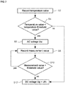
- FIG. 7 shows a flow chart of one embodiment of a method for operating an optoelectronic assembly
- FIG. 8 shows one example of a time/voltage diagram
- FIG. 9 shows a flow chart of one embodiment of a method for operating an optoelectronic assembly.
- An optoelectronic assembly may include one, two or more organic light-emitting components.
- an optoelectronic assembly may also include one, two or more electronic components.
- An electronic component may, for example, include an active and/or a passive component.
- An active electronic component may, for example, include a computation, sensor, control and/or regulating unit and/or a transistor.
- a passive electronic component may, for example, include a capacitor, a resistor, a diode or an inductor.
- An organic light-emitting component may, in various embodiments, be an organic light-emitting semiconductor component and/or be configured as an organic light-emitting diode, in particular as an OLED, or as an organic light-emitting transistor.
- the light may, for example, be light in the visible range, UV light and/or infrared light.
- the organic light-emitting component may, in various embodiments, be part of an integrated circuit.
- a multiplicity of organic light-emitting components may be provided, for example accommodated in a common housing of the optoelectronic assembly.
- FIG. 1 shows one embodiment of an optoelectronic component 1 .
- the optoelectronic component 1 includes a carrier 12 .
- the carrier 12 may be configured to be translucent or transparent.
- the carrier 12 serves as carrier element for electronic elements or layers, for example light-emitting elements.
- the carrier 12 may for example include or be formed from plastic, metal, glass, quartz and/or a semiconductor material.
- the carrier 12 may furthermore include or be formed from a plastic film or a laminate of one or more plastic films.
- the carrier 12 may be configured to be mechanically rigid or mechanically flexible.
- the optoelectronic layer structure includes a first electrode layer 14 , which includes a first contact section 16 , a second contact section 18 and a first electrode 20 .
- the carrier 12 with the first electrode layer 14 may also be referred to as the substrate.
- a first barrier layer (not represented), for example a first barrier thin film, may be formed between the carrier 12 and the first electrode layer 14 .
- the first electrode 20 is electrically insulated from the first contact section 16 by means of an electrical insulation barrier 21 .
- the second contact section 18 is electrically coupled to the first electrode 20 of the optoelectronic layer structure.
- the first electrode 20 may be configured as an anode or as a cathode.
- the first electrode 20 may be configured to be translucent or transparent.
- the first electrode 20 includes an electrically conductive material, for example metal and/or a transparent conductive oxide (TCO), or a layer stack of a plurality of layers which include metals or TCOs.
- the first electrode 20 may, for example, include a layer stack of a combination of a layer of a metal on a layer of a TCO, or vice versa.
- the first electrode 20 may include: networks of metal nanowires and nanoparticles, for example of Ag, networks of carbon nanotubes, graphite particles and graphite layers and/or networks of semiconducting nanowires.
- the organic functional layer structure 22 may for example include one, two or more sublayers.
- the organic functional layer structure 22 may include a hole injection layer, a hole transport layer, an emitter layer, an electron transport layer and/or an electron injection layer.
- the hole injection layer is used to reduce the band gap between the first electrode and the hole transport layer.
- the hole conductivity is greater than the electron conductivity.
- the hole transport layer is used for transporting the holes.
- the electron transport layer the electron conductivity is greater than the hole conductivity.
- the electron transport layer is used for transporting the holes.
- the electron injection layer is used to reduce the band gap between the second electrode and the electron transport layer.
- the organic functional layer structure 22 may include one, two or more functional layer structure units, which respectively include the aforementioned sublayers and/or further intermediate layers.
- the second electrode 23 is formed according to one of the configurations of the first electrode 20 , in which case the first electrode 20 and the second electrode 23 may be configured identically or differently.
- the first electrode 20 is used, for example, as an anode or cathode of the optoelectronic layer structure.
- the second electrode 23 is used as a cathode or anode of the optoelectronic layer structure.
- the optoelectronic layer structure is an electrically and/or optically active region.
- the active region is, for example, the region of the optoelectronic component 10 in which electrical current for operation of the optoelectronic component 10 flows and/or in which electromagnetic radiation is generated or absorbed.
- a getter structure (not represented) may be arranged on or over the active region.
- the getter layer may be configured to be translucent, transparent or opaque.
- the getter layer may include or be formed from a material which absorbs and binds substances that are harmful to the active region.
- the encapsulation layer 24 Formed over the second electrode 23 and partially over the first contact section 16 and partially over the second contact section 18 , there is an encapsulation layer 24 of the optoelectronic layer structure which encapsulates the optoelectronic layer structure.
- the encapsulation layer 24 may be configured as a second barrier layer, for example as a second barrier thin film.
- the encapsulation layer 24 may also be referred to as thin-film encapsulation.
- the encapsulation layer 24 forms a barrier against chemical contaminants or atmospheric substances, in particular against water (moisture) and oxygen.
- the encapsulation layer 24 may be formed as a single layer, a layer stack or a layer structure.
- the encapsulation layer 24 may include or be formed from: aluminum oxide, zinc oxide, zirconium oxide, titanium oxide, hafnium oxide, tantalum oxide, lanthanum oxide, silicon oxide, silicon nitride, silicon oxynitride, indium tin oxide, indium zinc oxide, aluminum-doped zinc oxide, poly(p-phenylene terephthalamide), nylon 66 , as well as mixtures and alloys thereof.
- the first barrier layer may be formed on the carrier 12 in accordance with one configuration of the encapsulation layer 24 .
- a first recess of the encapsulation layer 24 is formed over the first contact section 16 and a second recess of the encapsulation layer 24 is formed over the second contact section 18 .
- a first contact region 32 is exposed in the first recess of the encapsulation layer 24 and a second contact region 34 is exposed in the second recess of the encapsulation layer 24 .
- the first contact region 32 is used for electrically contacting the first contact section 16 and the second contact region 34 is used for electrically contacting the second contact section 18 .
- a bonding layer 36 is formed over the encapsulation layer 24 .
- the bonding layer 36 includes for example a bonding agent, for example an adhesive, for example a laminating adhesive, a coating and/or a resin.
- the bonding layer 36 may, for example, include particles which scatter electromagnetic radiation, for example light-scattering particles.
- a cover body 38 is formed over the bonding layer 36 .
- the bonding layer 36 is used for fastening the cover body 38 on the encapsulation layer 24 .
- the cover body 38 includes, for example, plastic, glass and/or metal.
- the cover body 38 may be formed essentially from glass and include a thin metal layer, for example a metal foil, and/or a graphite layer, for example a graphite laminate, on the glass body.
- the cover body 38 is used to protect the optoelectronic component 1 , for example against the effects of mechanical force from the outside.
- the cover body 38 may be used to distribute and/or dissipate heat which is generated in the optoelectronic component 1 .
- the glass of the cover body 38 may be used as protection against external influences, and the metal layer of the cover body 38 may be used to distribute and/or dissipate the heat given off during operation of the optoelectronic component 1 .
- FIG. 2 shows an equivalent circuit diagram of the organic light-emitting component 1 according to FIG. 1 .
- the organic functional layer structure 22 is represented as a diode 40 .
- the equivalent circuit diagram includes a capacitor 42 and a bulk resistor 44 , which are connected in parallel with the diode 40 and in parallel with one another.
- the capacitor 42 is formed by the electrodes 20 , 23 .
- the bulk resistor 44 is representative of one or more electrical resistances of one or correspondingly more leakage current paths between the electrodes 20 , 23 .
- the equivalent circuit diagram includes an electrode resistance 46 , which is connected in series with the diode 40 , the capacitor 42 and the bulk resistor 44 and is representative of the electrical resistances of the two electrodes 20 , 23 or of the electrical resistance of the first electrode 20 , if the electrical resistance of the second electrode is neglected.
- a voltage source 48 is represented.
- the voltage source 48 may for example be part of a controller, which will be explained in more detail below with reference to FIG. 5 .
- a voltage for example a DC voltage, which is greater than an instantaneous threshold voltage of the diode 40 , is then applied by means of the voltage source 48 to the electrode resistance 46 and the diode 40 , normal operation of the diode 40 begins, the diode 40 becomes luminescent and the organic functional layer structure 22 emits light.
- the diode 40 does not become luminescent and the diode 40 may be considered absent from the equivalent circuit diagram for the function of the organic light-emitting component 1 .
- the residual parasitic elements of the equivalent circuit diagram remain, in particular the electrode resistance 46 , the capacitor 42 and the bulk resistor 44 .
- the capacitor 42 This is not transmissive for the direct current, particularly during normal operation of the organic light-emitting component 1 , but represents only an alternating-current impedance for alternating current. This alternating-current impedance is commensurately lower when the capacitance is higher and/or the frequency of the AC voltage is higher. If the capacitor 42 as an alternating-current impedance is made to have a very low impedance with an AC voltage having a high frequency, the organic light-emitting component 1 can therefore be operated with a high alternating-current even with a low AC voltage, i.e. an AC voltage having a low amplitude.
- this alternating-current necessarily flows through the electrode resistance 46 and causes a voltage drop and heat loss there.
- the first electrode 20 is thereby heated directly, and the organic functional layer structure 22 is heated indirectly by means of the first electrode 20 .
- This heating is very efficient and takes place “from the inside out”. This effect may be used as a heating process before normal operation of the organic light-emitting component 1 when switching the organic light-emitting component 1 on.
- the AC voltage, even at maximum amplitude, is less than the instantaneous threshold voltage of the organic light-emitting component 1 , only a negligibly small current or no current at all flows through the organic functional layer structure 22 . If the AC voltage at maximum amplitude is somewhat greater than the instantaneous threshold voltage, current flows at least temporarily through the organic functional layer structure 22 .
- FIG. 3 shows a temperature/voltage diagram in which forward voltages during normal operation, i.e. during luminescent operation, of the organic light-emitting component 1 are represented as a function of an external temperature T of an environment of the organic light-emitting component 1 .
- the square measurement points are representative of values of the forward voltage at the corresponding external temperatures T when switching on the corresponding OLED.
- the triangular measurement points are representative of values of the forward voltage at the corresponding external temperatures T after a predetermined time duration, for example after a couple of minutes, after switching on the corresponding OLED.
- the diamond-shaped measurement points are representative of values of the forward voltage at the corresponding temperatures when switching on the corresponding OLED and after the predetermined time duration, since at these temperatures the values no longer differ from one another substantially and/or no longer significantly.
- the OLED corresponds essentially to the organic light-emitting component 1 as explained above.
- the temperature/voltage diagram shows that, with a decreasing external temperature T, the forward voltage required when switching on for normal operation increases, and that during operation of the OLED, for the same external temperature and with an increasing internal temperature, the forward voltage required for normal operation decreases.
- a controller which is capable of providing the entire represented range of forward voltages, even if the particularly low temperatures, for example below ⁇ 15° C., occur only seldom. Such a controller would be relatively expensive.
- FIG. 4 shows a time/temperature-difference diagram, in which the temperature difference is indicated as a function of time for different electrical powers.
- the diamond-shaped measurement points were recorded at a power of 2 W, the square measurement points at a power of 4 W and the triangular measurement points at a power of 6 W.
- the time/temperature-difference diagram shows that the time within which a desired temperature change can be achieved in the organic light-emitting component 1 depends on the electrical power introduced.
- the normal power of the OLED is for example 2 W
- the OLED would be stabilized, i.e. heated by 35° C., after about 160 s. But if a thermal power of for example 6 W is applied after switching on the OLED and before normal operation of the OLED, the desired 35° C. would already be achieved after about 20 s. After this, normal operation may be started. Because of the heating process by means of the AC voltage, normal operation can therefore already be started 120 s earlier than without heating.
- FIG. 5 shows a block diagram of one embodiment of an optoelectronic assembly 10 .
- the optoelectronic assembly 10 includes an organic light-emitting component, for example the organic light-emitting component 1 explained above, a controller 50 , a first sensor 52 and optionally a second sensor 54 .
- the controller 50 may, for example, be a driver.
- the first sensor 52 is a temperature sensor.
- the first sensor 52 is used to record a temperature value.
- the temperature value is representative of a temperature of the organic light-emitting component 1 , in particular the organic functional layer structure 22 , and/or an environment of the organic light-emitting component 1 .
- the first sensor 52 may be a current sensor for recording a current value of a forward current which flows through the organic light-emitting component 1 , or a clock for recording a time value of a time duration which has elapsed since the organic light-emitting component 1 was switched on.
- the second sensor 54 may be the current sensor or the clock.
- the optoelectronic assembly 10 may include a storage medium (not represented).
- the controller 50 is used to process the measurement values recorded by means of the sensors 52 , 54 and to control and/or regulate the organic light-emitting component 1 as a function of the measurement values recorded.
- the controller 50 is used to switch on the organic light-emitting component 1 and to heat it before normal operation, then operate it during normal operation, or to switch on the organic light-emitting component and only if necessary to heat it before normal operation, then operate it during normal operation.
- the heating may, for example, be identified as necessary by the controller 50 if the temperature value recorded is less than a predetermined temperature threshold value.
- FIG. 6 and FIG. 7 together serve to explain one embodiment of a method for operating an optoelectronic assembly, for example the optoelectronic assembly 10 explained above.
- FIG. 6 shows a time/voltage diagram, in which a first voltage profile 70 of an AC voltage, which is applied to the organic light-emitting component 1 during a heating phase, and a forward voltage Uf, which is applied to the organic light-emitting component 1 during normal operation, are represented as a solid line.
- An instantaneous threshold voltage Uth is furthermore represented as a dashed line. In FIG. 6 , the instantaneous threshold voltage Uth decreases with time during the heating phase, since the internal temperature of the organic light-emitting component 1 increases.
- a first current profile 72 of the current with which the organic light-emitting component 1 is operated is represented as a dot-and-dash line in the diagram shown in FIG. 6 .
- the represented oscillation of the AC voltage begins shortly after an instant t 0 at which the organic light-emitting component 1 was switched on and it was identified that the temperature of the organic light-emitting component 1 is so low that it needs to be heated before adopting normal operation.
- the heating phase is initiated.
- the AC voltage is applied until an instant t 1 at which it is identified that further heating of the organic light-emitting component 1 is no longer necessary.
- the heating phase is ended.
- a DC voltage in particular the forward voltage Uf, is applied to the organic light-emitting component 1 .
- the forward voltage Uf is less than the instantaneous threshold voltage Uth at the instant t 0 , and is greater than the instantaneous threshold voltage Uth at the instant t 1 and thereafter.
- the first current profile 72 follows the first voltage profile 70 .
- the first current profile 72 follows the first voltage profile 70 in the time intervals in which the AC voltage is less than the instantaneous threshold voltage Uth and in which no current flows through the organic functional layer structure 22 , and no light is emitted, with a phase shift of approximately 90°.
- the first current profile 72 follows the first voltage profile 70 in the time intervals in which the AC voltage is greater than the instantaneous threshold voltage Uth and in which current therefore flows through the organic functional layer structure 22 , and light is emitted, without a significant phase shift. After application of the DC voltage at the instant t 1 and start of normal operation, direct current flows through the organic light-emitting component 1 .
- the maximum amplitude of the first current profile 72 before the instant t 1 is greater than the constant value of the first current profile after the instant t 1 , i.e. during normal or rated operation. This can contribute to the RMS current value being particularly high during the heating phase, so that particularly rapid heating takes place.
- the first voltage profile 70 is sinusoidal. As an alternative thereto, the first voltage profile 70 may, for example, be sawtoothed or trapezoidal and/or bipolar or unipolar.
- the AC voltage is radiofrequency, for example in the kilohertz to megahertz range.
- the AC voltage may be configured as a function of the capacitance of the capacitor 42 , the electrode resistance 46 and/or the threshold voltage Uth of the organic light-emitting component 1 .
- the first voltage profile 70 may, in particular, run substantially below the instantaneous threshold voltage Uth, although it may also exceed the instantaneous threshold voltage Uth. In particular, the maximum amplitude of the first voltage profile 70 may exceed the instantaneous threshold voltage Uth.
- the former is for example particularly suitable for OLEDs having a high threshold voltage Uth, for example for OLEDs having multiply stacked organic functional layer structures 22 , since these can be heated with a particularly high current at a particularly low frequency.
- the heating power may, for example, be selected in such a way that the light-emitting component 1 is heated particularly rapidly but not to an unnecessarily great extent.
- a maximum desired temperature change may be selected in such a way that it corresponds to the temperature change may be during normal operation of the organic light-emitting component 1 , which is set up in a steady state after a sufficiently long time. This temperature change may, for example, be determined empirically in the factory.
- the heating energy may be adjusted by means of the frequency, the voltage amplitude and the time duration of the heating.
- the voltage and frequency may be selected in such a way that the current amplitude and/or the RMS current value of the alternating current are greater than the current value of the direct current during normal or rated operation.
- the RMS value of the alternating current may lie in the range of from one to twenty times the rated current, for example in the range of from three to fifteen times the rated current or in the range of from five to ten times the rated current.
- the rated operating current may, for example, be the direct current which is set up beyond the instant t 1 .
- FIG. 7 shows a flow chart of one embodiment of a method for operating an optoelectronic assembly, for example the optoelectronic assembly 10 explained above.
- the method is used to identify whether heating of the organic light-emitting component 1 is necessary, to carry out the heating when it is necessary, and to end the heating when it is no longer necessary, and then to switch over into normal operation.
- the method is carried out, in particular by the controller 50 , when the organic light-emitting component 1 is switched on.
- a step S 2 the temperature value is recorded, for example with the aid of the first sensor 52 explained above.
- a check is made whether the temperature value recorded is less than a predetermined temperature threshold value. If the condition in step S 4 is satisfied, the processing is continued in a step S 6 . If the condition in step S 4 is not satisfied, the processing is continued in a step S 12 .
- an AC voltage Uw is applied to the organic light-emitting component 1 .
- the AC voltage Uw is at least temporarily less than the instantaneous threshold voltage Uth of the organic light-emitting component 1 .
- a measurement value is recorded.
- a temperature value may again be recorded.
- a current value of a forward current which flows through the organic functional layer structure 22 may be recorded, or a time value of a time duration which has elapsed since the organic light-emitting component 1 was switched on may be recorded. If the current value is recorded as the measurement value, a maximum of the alternating current amplitude may for example be recorded or measured as the measurement value.
- a check is made whether the measurement value recorded is less than a predetermined threshold value.
- a check may be made whether the temperature value recorded is less than the predetermined temperature threshold value.
- the temperature threshold value specified in step S 10 may be the same temperature threshold value or a different temperature threshold value than the temperature threshold value specified in step S 4 .
- a check may be made whether the current value is less than a predetermined current threshold value or the time value is less than a predetermined time threshold value.
- the predetermined current threshold value and/or the predetermined time threshold value may, for example, be determined in the factory and specified in such a way that the organic functional layer structure 22 reliably has a sufficient temperature for normal operation when they are exceeded.
- the predetermined current threshold value may lie in a range of for example from 20% to 100% of the OLED rated operating current, for example from 40% to 90% of the rated operating current, for example from 60% to 80% of the rated operating current.
- the predetermined time threshold value may lie in a range of for example from 0.2 s to 30 s, in particular from 0.5 s to 10 s, for example from 1 to 5 s. If the condition in step S 10 is satisfied, the processing is continued again in step S 8 . If the condition of step S 10 is not satisfied, the processing is continued in step S 12 .
- step S 12 a DC voltage Ug is applied to the organic light-emitting component 1 , the DC voltage Ug being greater than the instantaneous threshold voltage Uth.
- steps S 2 to S 10 represent the heating process after switching on and before normal operation of the organic light-emitting component 1 .
- FIG. 8 and FIG. 9 together serve to explain one embodiment of a method for operating an optoelectronic assembly, for example the optoelectronic assembly 10 explained above.
- FIG. 8 shows a time/voltage diagram, in which a second voltage profile 80 of an AC voltage, which is applied to the organic light-emitting component 1 during the heating phase, and a forward voltage Uf, which is applied to the organic light-emitting component 1 during normal operation, are represented as a solid line.
- An instantaneous threshold voltage Uth is furthermore represented as a dashed line. The instantaneous threshold voltage Uth decreases during the heating phase because of the increasing internal temperature of the organic light-emitting component 1 .
- a second current profile 82 of the current with which the organic light-emitting component 1 is operated is represented as a dot-and-dash line in the diagram shown in FIG. 8 .
- the represented oscillation of the AC voltage begins at an instant t 0 at which the organic light-emitting component 1 was switched on.
- the AC voltage is used to heat the organic light-emitting component 1 , and is mandatorily applied at least temporarily each time the organic light-emitting component 1 is switched on.
- the AC voltage is applied until an instant t 1 at which it is identified that further heating of the organic light-emitting component 1 is no longer necessary.
- a DC voltage in particular the forward voltage Uf, is applied to the organic light-emitting component 1 .
- the DC voltage is less than the instantaneous threshold voltage at the instant t 0 and greater than the instantaneous threshold voltage Uth at the instant t 1 .
- the second current profile 82 follows the second voltage profile 80 in the time intervals in which the AC voltage is less than the instantaneous threshold voltage Uth and in which no current flows through the organic functional layer structure 22 , and no light is emitted, with a phase shift of 90°.
- the maximum amplitude of the second current profile 82 before the instant t 1 i.e. during the heating phase, is greater than the constant value of the first current profile after the instant t 1 , i.e. during normal or rated operation. This can contribute to the RMS current value being particularly high during the heating phase, so that particularly rapid heating takes place.
- the second voltage profile 80 is sinusoidal. As an alternative thereto, the second voltage profile 80 may be sawtoothed or trapezoidal and/or bipolar or unipolar.
- the AC voltage is radiofrequency, for example in the kilohertz to megahertz range.
- the AC voltage may be configured as a function of the capacitance of the capacitor 42 , the electrode resistance 46 and/or the threshold voltage Uth of the organic light-emitting component 1 .
- the maximum amplitude of the second voltage profile 80 is always less than the instantaneous threshold voltage Uth. This is particularly favorable for OLEDs having a high threshold voltage Uth, for example for OLEDs having multiply stacked organic functional layer structures 22 , since these can be heated with a particularly high current at a particularly low frequency.
- the heating power may, for example, be selected in such a way that the light-emitting component 1 is heated particularly rapidly but not to an unnecessarily great extent.
- a maximum desired temperature change may be selected in such a way that it corresponds to the temperature change during normal operation of the organic light-emitting component 1 , which is set up in a steady state after a sufficiently long time. This temperature change may, for example, be determined empirically in the factory.
- the heating energy may be adjusted by means of the frequency, the voltage amplitude and the time duration of the heating.
- the voltage and frequency may be selected in such a way that the current amplitude and/or the RMS current value of the alternating current are greater than the current value of the direct current during normal or rated operation.
- the RMS value of the alternating current may lie in the range of from one to twenty times the rated current, for example in the range of from three to fifteen times the rated current or in the range of from five to ten times the rated current.
- the rated operating current may, for example, be the direct current which is set up beyond the instant t 1 .
- FIG. 9 shows a flow chart of one embodiment of a method for operating an optoelectronic assembly, for example the optoelectronic assembly 10 explained above.
- the method is carried out each time the organic light-emitting component 1 is switched on.
- the method is used to carry out heating of the organic light-emitting component 1 , to end the heating when it is no longer necessary, and then to switch over into normal operation.
- the method is carried out, in particular by the controller 50 .
- a step S 20 an AC voltage Uw is applied to the organic light-emitting component 1 , the AC voltage Uw being at all times less than an instantaneous threshold voltage Uth of the organic light-emitting component 1 .
- a measurement value is recorded.
- the temperature value is recorded.
- the current value or the time value may be recorded.
- a check is made whether the measurement value recorded is less than a predetermined threshold value. For example, a check is made whether the temperature value is less than the predetermined temperature threshold value, the current value is less than the predetermined current threshold value or the time value is less than the predetermined time threshold value. If the condition in step S 24 is satisfied, processing is continued again in step S 22 . If the condition in step S 24 is not satisfied, processing is continued in a step S 26 .
- step S 26 a DC voltage Ug is applied to the organic light-emitting component 1 , the DC voltage Ug being greater than the instantaneous threshold voltage Uth at the instant t 1 .
- normal operation, in particular luminescent operation, of the organic light-emitting component 1 is adopted in step S 26 .
- the threshold voltage Uth may vary in all embodiments.
- the voltage profiles may be selected in a different way than the voltage profiles represented in terms of their phase, amplitude and/or shape.
- the organic light-emitting component 1 may differ in detail from the organic light-emitting component 1 represented, in which case for example the cover body and/or the substrate may be omitted and/or it may include further electronic, optical and/or optoelectronic elements.
- the optoelectronic assembly 10 represented may include further electronic components, for example a storage medium, or further organic light-emitting components 1 .
Landscapes
- Electroluminescent Light Sources (AREA)
Abstract
Description
Claims (21)
Applications Claiming Priority (4)
| Application Number | Priority Date | Filing Date | Title |
|---|---|---|---|
| DE102015112635 | 2015-07-31 | ||
| DE102015112635.4A DE102015112635B4 (en) | 2015-07-31 | 2015-07-31 | Optoelectronic assembly and method for operating an optoelectronic assembly |
| DE102015112635.4 | 2015-07-31 | ||
| PCT/EP2016/068041 WO2017021276A1 (en) | 2015-07-31 | 2016-07-28 | Optoelectronic assembly and method for operating an optoelectronic assembly |
Publications (2)
| Publication Number | Publication Date |
|---|---|
| US20180220509A1 US20180220509A1 (en) | 2018-08-02 |
| US10531536B2 true US10531536B2 (en) | 2020-01-07 |
Family
ID=56686777
Family Applications (1)
| Application Number | Title | Priority Date | Filing Date |
|---|---|---|---|
| US15/748,666 Active US10531536B2 (en) | 2015-07-31 | 2016-07-28 | Optoelectronic assembly and method for operating an optoelectronic assembly |
Country Status (4)
| Country | Link |
|---|---|
| US (1) | US10531536B2 (en) |
| EP (1) | EP3329741B1 (en) |
| DE (1) | DE102015112635B4 (en) |
| WO (1) | WO2017021276A1 (en) |
Citations (11)
| Publication number | Priority date | Publication date | Assignee | Title |
|---|---|---|---|---|
| US6313589B1 (en) | 1999-11-16 | 2001-11-06 | Tokiwa Dengyo Co., Ltd. | Power supply circuit for traffic signal lights utilizing LEDs |
| US20060202914A1 (en) | 2005-03-03 | 2006-09-14 | Ian Ashdown | Method and apparatus for controlling thermal stress in lighting devices |
| US20090066267A1 (en) * | 2007-08-30 | 2009-03-12 | Osram Gesellschaft Mit Beshrankter Haftung | Arrangement and method for driving light-emitting components |
| US7576493B2 (en) | 2006-03-15 | 2009-08-18 | Yujing Technology Ltd | Vehicle LED lamp controller used in low temperature environment |
| US20110266958A1 (en) * | 2010-05-03 | 2011-11-03 | Wen-Kuei Tsai | Ac led apparatus |
| US20120249516A1 (en) | 2011-04-01 | 2012-10-04 | Emagin Corporation | Amoled microdisplay device with active temperature control |
| US20120280636A1 (en) * | 2011-05-05 | 2012-11-08 | General Electric Company | Self-dimming oled lighting system and control method |
| WO2014037908A1 (en) | 2012-09-07 | 2014-03-13 | Koninklijke Philips N.V. | Lighting device with integrated lens heat sink |
| US20140117853A1 (en) * | 2012-10-25 | 2014-05-01 | M-Systems Co., Ltd. | Led lamp, illumination device including the led lamp and current control method of the led lamp |
| US8866402B2 (en) * | 2010-02-16 | 2014-10-21 | Tai-Her Yang | Current regulator drive circuit shunting current by voltage-dividing load |
| DE102013107225A1 (en) | 2013-07-09 | 2015-01-15 | Osram Oled Gmbh | Optoelectronic component arrangement, method for producing an optoelectronic component arrangement, method for operating an optoelectronic component arrangement |
Family Cites Families (1)
| Publication number | Priority date | Publication date | Assignee | Title |
|---|---|---|---|---|
| DE102012000623A1 (en) | 2012-01-14 | 2013-07-18 | Volkswagen Aktiengesellschaft | Temperature monitoring of lighting devices |
-
2015
- 2015-07-31 DE DE102015112635.4A patent/DE102015112635B4/en active Active
-
2016
- 2016-07-28 EP EP16751526.1A patent/EP3329741B1/en active Active
- 2016-07-28 US US15/748,666 patent/US10531536B2/en active Active
- 2016-07-28 WO PCT/EP2016/068041 patent/WO2017021276A1/en not_active Ceased
Patent Citations (11)
| Publication number | Priority date | Publication date | Assignee | Title |
|---|---|---|---|---|
| US6313589B1 (en) | 1999-11-16 | 2001-11-06 | Tokiwa Dengyo Co., Ltd. | Power supply circuit for traffic signal lights utilizing LEDs |
| US20060202914A1 (en) | 2005-03-03 | 2006-09-14 | Ian Ashdown | Method and apparatus for controlling thermal stress in lighting devices |
| US7576493B2 (en) | 2006-03-15 | 2009-08-18 | Yujing Technology Ltd | Vehicle LED lamp controller used in low temperature environment |
| US20090066267A1 (en) * | 2007-08-30 | 2009-03-12 | Osram Gesellschaft Mit Beshrankter Haftung | Arrangement and method for driving light-emitting components |
| US8866402B2 (en) * | 2010-02-16 | 2014-10-21 | Tai-Her Yang | Current regulator drive circuit shunting current by voltage-dividing load |
| US20110266958A1 (en) * | 2010-05-03 | 2011-11-03 | Wen-Kuei Tsai | Ac led apparatus |
| US20120249516A1 (en) | 2011-04-01 | 2012-10-04 | Emagin Corporation | Amoled microdisplay device with active temperature control |
| US20120280636A1 (en) * | 2011-05-05 | 2012-11-08 | General Electric Company | Self-dimming oled lighting system and control method |
| WO2014037908A1 (en) | 2012-09-07 | 2014-03-13 | Koninklijke Philips N.V. | Lighting device with integrated lens heat sink |
| US20140117853A1 (en) * | 2012-10-25 | 2014-05-01 | M-Systems Co., Ltd. | Led lamp, illumination device including the led lamp and current control method of the led lamp |
| DE102013107225A1 (en) | 2013-07-09 | 2015-01-15 | Osram Oled Gmbh | Optoelectronic component arrangement, method for producing an optoelectronic component arrangement, method for operating an optoelectronic component arrangement |
Non-Patent Citations (2)
| Title |
|---|
| German Search Report based on application No. 10 2015 112 635.4 (10 pages) dated Feb. 4, 2016 (for reference purpose only). |
| International Search Report based on application No. PCT/EP2016/068041 (6 pages + 3 pages English translation) dated Oct. 31, 2016 (for reference purpose only). |
Also Published As
| Publication number | Publication date |
|---|---|
| WO2017021276A1 (en) | 2017-02-09 |
| DE102015112635B4 (en) | 2022-11-24 |
| EP3329741C0 (en) | 2023-10-04 |
| US20180220509A1 (en) | 2018-08-02 |
| DE102015112635A1 (en) | 2017-02-02 |
| EP3329741A1 (en) | 2018-06-06 |
| EP3329741B1 (en) | 2023-10-04 |
Similar Documents
| Publication | Publication Date | Title |
|---|---|---|
| US10578665B2 (en) | Method for identifying a short circuit in a first light emitting diode element, and optoelectronic subassembly | |
| US8563903B2 (en) | Method and circuit for controlling radiant heat of transistor using metal-insulator transition device | |
| EP2248169B1 (en) | Circuit for preventing self-heating of metal-insulator-transition (mit) device and method of fabricating integrated-device with the same circuit | |
| US8420987B2 (en) | Thermistor with 3 terminals, thermistor-transistor, circuit for controlling heat of power transistor using the thermistor-transistor, and power system including the circuit | |
| US7859213B2 (en) | Control device and control method | |
| US20100090728A1 (en) | Driver and Method for Driving a Device | |
| US11659733B2 (en) | Optoelectronic assembly and method for producing an optoelectronic assembly | |
| US7235921B2 (en) | Organic electroluminescent element with particular electrode terminal structure | |
| US10165648B2 (en) | Optoelectronic circuit and method for operating an optoelectronic circuit | |
| CN204442883U (en) | For the cooling system of cooling heat generation device | |
| US10334691B2 (en) | Organic light-emitting component device, method for producing an organic light-emitting component device and method for operating an organic light-emitting component device | |
| US10531536B2 (en) | Optoelectronic assembly and method for operating an optoelectronic assembly | |
| US10074829B2 (en) | Optoelectronic component device, method for producing an optoelectronic component device, and method for operating an optoelectronic component device | |
| US9923173B2 (en) | Optoelectronic component and method for producing an optoelectronic component | |
| US20160233398A1 (en) | Optoelectronic component and method for producing an optoelectronic component | |
| US9848508B1 (en) | Cooling systems and synthetic jets configured to harvest energy and vehicles including the same | |
| US10629844B2 (en) | Organic optoelectronic component and method for producing an organic optoelectronic component | |
| US10249845B2 (en) | Optoelectronic component and method for producing an optoelectronic component | |
| US20170273155A1 (en) | Apparatus for controlling light emitting diode module having light intensity compensation function and lighting system including the same | |
| JP2000156292A (en) | Electric element | |
| US20160118617A1 (en) | Organic el element | |
| TW201006303A (en) | OLED device with current limiting layer | |
| Huang et al. | A silicon-based LED packaging module with a temperature-dependent capacitor for constant voltage control | |
| CN121415724A (en) | Low-temperature high-efficiency electric field driving light-emitting method applied to electronic display screen | |
| Nair et al. | On the efficiency roll-off in Perovskite Light Emitting Diodes |
Legal Events
| Date | Code | Title | Description |
|---|---|---|---|
| FEPP | Fee payment procedure |
Free format text: ENTITY STATUS SET TO UNDISCOUNTED (ORIGINAL EVENT CODE: BIG.); ENTITY STATUS OF PATENT OWNER: LARGE ENTITY |
|
| AS | Assignment |
Owner name: OSRAM OLED GMBH, GERMANY Free format text: ASSIGNMENT OF ASSIGNORS INTEREST;ASSIGNORS:REGAU, KILIAN;FARRNBACHER, JOERG;HOEFLINGER, BENJAMIN;AND OTHERS;SIGNING DATES FROM 20171206 TO 20180802;REEL/FRAME:047061/0408 |
|
| STPP | Information on status: patent application and granting procedure in general |
Free format text: DOCKETED NEW CASE - READY FOR EXAMINATION |
|
| STPP | Information on status: patent application and granting procedure in general |
Free format text: NON FINAL ACTION MAILED |
|
| STPP | Information on status: patent application and granting procedure in general |
Free format text: RESPONSE TO NON-FINAL OFFICE ACTION ENTERED AND FORWARDED TO EXAMINER |
|
| STPP | Information on status: patent application and granting procedure in general |
Free format text: NOTICE OF ALLOWANCE MAILED -- APPLICATION RECEIVED IN OFFICE OF PUBLICATIONS |
|
| STPP | Information on status: patent application and granting procedure in general |
Free format text: PUBLICATIONS -- ISSUE FEE PAYMENT VERIFIED |
|
| STCF | Information on status: patent grant |
Free format text: PATENTED CASE |
|
| AS | Assignment |
Owner name: PICTIVA DISPLAYS INTERNATIONAL LIMITED, IRELAND Free format text: CORRECTIVE ASSIGNMENT TO CORRECT THE 11/658.772 REPLACED 11/658.772 PROPERTY NUMBERS PREVIOUSLY RECORDED AT REEL: 053464 FRAME: 0395. ASSIGNOR(S) HEREBY CONFIRMS THE ASSIGNMENT;ASSIGNOR:DOLYA HOLDCO 5 LIMITED;REEL/FRAME:053464/0395 Effective date: 20200717 Owner name: PICTIVA DISPLAYS INTERNATIONAL LIMITED, IRELAND Free format text: CHANGE OF NAME;ASSIGNOR:DOLYA HOLDCO 5 LIMITED;REEL/FRAME:053464/0395 Effective date: 20200717 Owner name: DOLYA HOLDCO 5 LIMITED, IRELAND Free format text: ASSIGNMENT OF ASSIGNORS INTEREST;ASSIGNOR:OSRAM OLED GMBH;REEL/FRAME:053464/0374 Effective date: 20200703 |
|
| MAFP | Maintenance fee payment |
Free format text: PAYMENT OF MAINTENANCE FEE, 4TH YEAR, LARGE ENTITY (ORIGINAL EVENT CODE: M1551); ENTITY STATUS OF PATENT OWNER: LARGE ENTITY Year of fee payment: 4 |