US10530126B2 - External cavity laser - Google Patents
External cavity laser Download PDFInfo
- Publication number
- US10530126B2 US10530126B2 US15/855,328 US201715855328A US10530126B2 US 10530126 B2 US10530126 B2 US 10530126B2 US 201715855328 A US201715855328 A US 201715855328A US 10530126 B2 US10530126 B2 US 10530126B2
- Authority
- US
- United States
- Prior art keywords
- port
- light
- gain medium
- input
- wavelengths
- Prior art date
- Legal status (The legal status is an assumption and is not a legal conclusion. Google has not performed a legal analysis and makes no representation as to the accuracy of the status listed.)
- Expired - Fee Related
Links
- 230000000737 periodic effect Effects 0.000 claims abstract description 18
- 230000003287 optical effect Effects 0.000 claims description 34
- 229910052581 Si3N4 Inorganic materials 0.000 claims description 8
- 230000008878 coupling Effects 0.000 claims description 8
- 238000010168 coupling process Methods 0.000 claims description 8
- 238000005859 coupling reaction Methods 0.000 claims description 8
- HQVNEWCFYHHQES-UHFFFAOYSA-N silicon nitride Chemical compound N12[Si]34N5[Si]62N3[Si]51N64 HQVNEWCFYHHQES-UHFFFAOYSA-N 0.000 claims description 8
- 230000001154 acute effect Effects 0.000 claims description 4
- 238000005253 cladding Methods 0.000 claims description 4
- 238000002310 reflectometry Methods 0.000 claims description 4
- 239000004065 semiconductor Substances 0.000 abstract description 19
- XUIMIQQOPSSXEZ-UHFFFAOYSA-N Silicon Chemical compound [Si] XUIMIQQOPSSXEZ-UHFFFAOYSA-N 0.000 abstract description 15
- 229910052710 silicon Inorganic materials 0.000 abstract description 15
- 239000010703 silicon Substances 0.000 abstract description 15
- 229910052732 germanium Inorganic materials 0.000 abstract description 5
- GNPVGFCGXDBREM-UHFFFAOYSA-N germanium atom Chemical compound [Ge] GNPVGFCGXDBREM-UHFFFAOYSA-N 0.000 abstract description 5
- 239000000463 material Substances 0.000 description 12
- 238000012544 monitoring process Methods 0.000 description 10
- 238000000034 method Methods 0.000 description 9
- VYPSYNLAJGMNEJ-UHFFFAOYSA-N Silicium dioxide Chemical compound O=[Si]=O VYPSYNLAJGMNEJ-UHFFFAOYSA-N 0.000 description 6
- 239000011248 coating agent Substances 0.000 description 5
- 238000000576 coating method Methods 0.000 description 5
- 230000000694 effects Effects 0.000 description 5
- 230000008569 process Effects 0.000 description 5
- 239000000758 substrate Substances 0.000 description 5
- GPXJNWSHGFTCBW-UHFFFAOYSA-N Indium phosphide Chemical compound [In]#P GPXJNWSHGFTCBW-UHFFFAOYSA-N 0.000 description 4
- 230000001427 coherent effect Effects 0.000 description 4
- 238000002347 injection Methods 0.000 description 4
- 239000007924 injection Substances 0.000 description 4
- 230000005540 biological transmission Effects 0.000 description 3
- 230000010354 integration Effects 0.000 description 3
- 238000004519 manufacturing process Methods 0.000 description 3
- 230000006798 recombination Effects 0.000 description 3
- 238000005215 recombination Methods 0.000 description 3
- 239000000377 silicon dioxide Substances 0.000 description 3
- 238000012360 testing method Methods 0.000 description 3
- 235000008694 Humulus lupulus Nutrition 0.000 description 2
- 230000008901 benefit Effects 0.000 description 2
- 229910052681 coesite Inorganic materials 0.000 description 2
- 238000004891 communication Methods 0.000 description 2
- 229910052906 cristobalite Inorganic materials 0.000 description 2
- 230000009977 dual effect Effects 0.000 description 2
- 239000012212 insulator Substances 0.000 description 2
- 239000002184 metal Substances 0.000 description 2
- 229910052751 metal Inorganic materials 0.000 description 2
- 239000002096 quantum dot Chemical group 0.000 description 2
- 238000001228 spectrum Methods 0.000 description 2
- 229910052682 stishovite Inorganic materials 0.000 description 2
- 229910052905 tridymite Inorganic materials 0.000 description 2
- 238000010521 absorption reaction Methods 0.000 description 1
- 238000013459 approach Methods 0.000 description 1
- 230000008033 biological extinction Effects 0.000 description 1
- 230000000295 complement effect Effects 0.000 description 1
- 238000007906 compression Methods 0.000 description 1
- 238000012790 confirmation Methods 0.000 description 1
- 238000013461 design Methods 0.000 description 1
- 238000005516 engineering process Methods 0.000 description 1
- 238000005530 etching Methods 0.000 description 1
- PCHJSUWPFVWCPO-UHFFFAOYSA-N gold Chemical compound [Au] PCHJSUWPFVWCPO-UHFFFAOYSA-N 0.000 description 1
- 239000010931 gold Substances 0.000 description 1
- 229910052737 gold Inorganic materials 0.000 description 1
- 238000001459 lithography Methods 0.000 description 1
- 238000005259 measurement Methods 0.000 description 1
- 238000012986 modification Methods 0.000 description 1
- 230000004048 modification Effects 0.000 description 1
- 230000010363 phase shift Effects 0.000 description 1
- 238000012545 processing Methods 0.000 description 1
- 235000012239 silicon dioxide Nutrition 0.000 description 1
Images


Classifications
-
- H—ELECTRICITY
- H01—ELECTRIC ELEMENTS
- H01S—DEVICES USING THE PROCESS OF LIGHT AMPLIFICATION BY STIMULATED EMISSION OF RADIATION [LASER] TO AMPLIFY OR GENERATE LIGHT; DEVICES USING STIMULATED EMISSION OF ELECTROMAGNETIC RADIATION IN WAVE RANGES OTHER THAN OPTICAL
- H01S5/00—Semiconductor lasers
- H01S5/10—Construction or shape of the optical resonator, e.g. extended or external cavity, coupled cavities, bent-guide, varying width, thickness or composition of the active region
- H01S5/14—External cavity lasers
- H01S5/141—External cavity lasers using a wavelength selective device, e.g. a grating or etalon
-
- H—ELECTRICITY
- H01—ELECTRIC ELEMENTS
- H01S—DEVICES USING THE PROCESS OF LIGHT AMPLIFICATION BY STIMULATED EMISSION OF RADIATION [LASER] TO AMPLIFY OR GENERATE LIGHT; DEVICES USING STIMULATED EMISSION OF ELECTROMAGNETIC RADIATION IN WAVE RANGES OTHER THAN OPTICAL
- H01S3/00—Lasers, i.e. devices using stimulated emission of electromagnetic radiation in the infrared, visible or ultraviolet wave range
- H01S3/05—Construction or shape of optical resonators; Accommodation of active medium therein; Shape of active medium
- H01S3/08—Construction or shape of optical resonators or components thereof
- H01S3/081—Construction or shape of optical resonators or components thereof comprising three or more reflectors
- H01S3/083—Ring lasers
-
- H—ELECTRICITY
- H01—ELECTRIC ELEMENTS
- H01S—DEVICES USING THE PROCESS OF LIGHT AMPLIFICATION BY STIMULATED EMISSION OF RADIATION [LASER] TO AMPLIFY OR GENERATE LIGHT; DEVICES USING STIMULATED EMISSION OF ELECTROMAGNETIC RADIATION IN WAVE RANGES OTHER THAN OPTICAL
- H01S3/00—Lasers, i.e. devices using stimulated emission of electromagnetic radiation in the infrared, visible or ultraviolet wave range
- H01S3/10—Controlling the intensity, frequency, phase, polarisation or direction of the emitted radiation, e.g. switching, gating, modulating or demodulating
- H01S3/13—Stabilisation of laser output parameters, e.g. frequency or amplitude
- H01S3/1307—Stabilisation of the phase
-
- H—ELECTRICITY
- H01—ELECTRIC ELEMENTS
- H01S—DEVICES USING THE PROCESS OF LIGHT AMPLIFICATION BY STIMULATED EMISSION OF RADIATION [LASER] TO AMPLIFY OR GENERATE LIGHT; DEVICES USING STIMULATED EMISSION OF ELECTROMAGNETIC RADIATION IN WAVE RANGES OTHER THAN OPTICAL
- H01S5/00—Semiconductor lasers
- H01S5/02—Structural details or components not essential to laser action
- H01S5/0206—Substrates, e.g. growth, shape, material, removal or bonding
- H01S5/021—Silicon based substrates
-
- H—ELECTRICITY
- H01—ELECTRIC ELEMENTS
- H01S—DEVICES USING THE PROCESS OF LIGHT AMPLIFICATION BY STIMULATED EMISSION OF RADIATION [LASER] TO AMPLIFY OR GENERATE LIGHT; DEVICES USING STIMULATED EMISSION OF ELECTROMAGNETIC RADIATION IN WAVE RANGES OTHER THAN OPTICAL
- H01S5/00—Semiconductor lasers
- H01S5/06—Arrangements for controlling the laser output parameters, e.g. by operating on the active medium
- H01S5/068—Stabilisation of laser output parameters
- H01S5/06821—Stabilising other output parameters than intensity or frequency, e.g. phase, polarisation or far-fields
-
- H—ELECTRICITY
- H01—ELECTRIC ELEMENTS
- H01S—DEVICES USING THE PROCESS OF LIGHT AMPLIFICATION BY STIMULATED EMISSION OF RADIATION [LASER] TO AMPLIFY OR GENERATE LIGHT; DEVICES USING STIMULATED EMISSION OF ELECTROMAGNETIC RADIATION IN WAVE RANGES OTHER THAN OPTICAL
- H01S5/00—Semiconductor lasers
- H01S5/10—Construction or shape of the optical resonator, e.g. extended or external cavity, coupled cavities, bent-guide, varying width, thickness or composition of the active region
- H01S5/1003—Waveguide having a modified shape along the axis, e.g. branched, curved, tapered, voids
- H01S5/1014—Tapered waveguide, e.g. spotsize converter
-
- H—ELECTRICITY
- H01—ELECTRIC ELEMENTS
- H01S—DEVICES USING THE PROCESS OF LIGHT AMPLIFICATION BY STIMULATED EMISSION OF RADIATION [LASER] TO AMPLIFY OR GENERATE LIGHT; DEVICES USING STIMULATED EMISSION OF ELECTROMAGNETIC RADIATION IN WAVE RANGES OTHER THAN OPTICAL
- H01S5/00—Semiconductor lasers
- H01S5/10—Construction or shape of the optical resonator, e.g. extended or external cavity, coupled cavities, bent-guide, varying width, thickness or composition of the active region
- H01S5/1025—Extended cavities
-
- H—ELECTRICITY
- H01—ELECTRIC ELEMENTS
- H01S—DEVICES USING THE PROCESS OF LIGHT AMPLIFICATION BY STIMULATED EMISSION OF RADIATION [LASER] TO AMPLIFY OR GENERATE LIGHT; DEVICES USING STIMULATED EMISSION OF ELECTROMAGNETIC RADIATION IN WAVE RANGES OTHER THAN OPTICAL
- H01S5/00—Semiconductor lasers
- H01S5/10—Construction or shape of the optical resonator, e.g. extended or external cavity, coupled cavities, bent-guide, varying width, thickness or composition of the active region
- H01S5/14—External cavity lasers
- H01S5/141—External cavity lasers using a wavelength selective device, e.g. a grating or etalon
- H01S5/142—External cavity lasers using a wavelength selective device, e.g. a grating or etalon which comprises an additional resonator
-
- H—ELECTRICITY
- H01—ELECTRIC ELEMENTS
- H01S—DEVICES USING THE PROCESS OF LIGHT AMPLIFICATION BY STIMULATED EMISSION OF RADIATION [LASER] TO AMPLIFY OR GENERATE LIGHT; DEVICES USING STIMULATED EMISSION OF ELECTROMAGNETIC RADIATION IN WAVE RANGES OTHER THAN OPTICAL
- H01S3/00—Lasers, i.e. devices using stimulated emission of electromagnetic radiation in the infrared, visible or ultraviolet wave range
- H01S3/10—Controlling the intensity, frequency, phase, polarisation or direction of the emitted radiation, e.g. switching, gating, modulating or demodulating
- H01S3/106—Controlling the intensity, frequency, phase, polarisation or direction of the emitted radiation, e.g. switching, gating, modulating or demodulating by controlling devices placed within the cavity
-
- H—ELECTRICITY
- H01—ELECTRIC ELEMENTS
- H01S—DEVICES USING THE PROCESS OF LIGHT AMPLIFICATION BY STIMULATED EMISSION OF RADIATION [LASER] TO AMPLIFY OR GENERATE LIGHT; DEVICES USING STIMULATED EMISSION OF ELECTROMAGNETIC RADIATION IN WAVE RANGES OTHER THAN OPTICAL
- H01S5/00—Semiconductor lasers
- H01S5/02—Structural details or components not essential to laser action
- H01S5/028—Coatings ; Treatment of the laser facets, e.g. etching, passivation layers or reflecting layers
- H01S5/0287—Facet reflectivity
-
- H—ELECTRICITY
- H01—ELECTRIC ELEMENTS
- H01S—DEVICES USING THE PROCESS OF LIGHT AMPLIFICATION BY STIMULATED EMISSION OF RADIATION [LASER] TO AMPLIFY OR GENERATE LIGHT; DEVICES USING STIMULATED EMISSION OF ELECTROMAGNETIC RADIATION IN WAVE RANGES OTHER THAN OPTICAL
- H01S5/00—Semiconductor lasers
- H01S5/40—Arrangement of two or more semiconductor lasers, not provided for in groups H01S5/02 - H01S5/30
- H01S5/4025—Array arrangements, e.g. constituted by discrete laser diodes or laser bar
- H01S5/4031—Edge-emitting structures
- H01S5/4062—Edge-emitting structures with an external cavity or using internal filters, e.g. Talbot filters
-
- H—ELECTRICITY
- H01—ELECTRIC ELEMENTS
- H01S—DEVICES USING THE PROCESS OF LIGHT AMPLIFICATION BY STIMULATED EMISSION OF RADIATION [LASER] TO AMPLIFY OR GENERATE LIGHT; DEVICES USING STIMULATED EMISSION OF ELECTROMAGNETIC RADIATION IN WAVE RANGES OTHER THAN OPTICAL
- H01S5/00—Semiconductor lasers
- H01S5/40—Arrangement of two or more semiconductor lasers, not provided for in groups H01S5/02 - H01S5/30
- H01S5/4025—Array arrangements, e.g. constituted by discrete laser diodes or laser bar
- H01S5/4087—Array arrangements, e.g. constituted by discrete laser diodes or laser bar emitting more than one wavelength
Definitions
- the present invention relates to an external cavity laser, and in particular to an external cavity laser for use in semiconductor photonics.
- Lasing is a radiative recombination process in semiconductors, in which an electron in the conduction recombines with a hole in the valance band and a photon is emitted.
- the reverse process is electron hole pair generation through optical absorption, which occurs in such devices as photodetectors and solar cells.
- DBRs Distributed Bragg Reflectors
- An object of the present invention is to overcome the shortcomings of the prior art by providing an external cavity laser for integrated semiconductor photonics.
- an external cavity laser comprising:
- a splitter including an input port optically coupled to the gain medium, an input/output port, and an output port for outputting laser light at selected wavelengths;
- a wavelength selective reflector optically coupled to the input/output port for reflecting light of one or more selected wavelengths back to the gain medium via the input/output port forming a laser cavity with the reflective surface, and passing light of non-selected wavelengths.
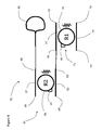
- FIG. 1 is a schematic view in accordance with an embodiment of the present invention
- FIG. 2 is a schematic view of an alternative embodiment of the present invention.
- FIG. 3 a is a schematic view of an embodiment of a wavelength selective reflector in accordance with the device of FIG. 1 or 2 ;
- FIG. 3 b is a schematic view of an embodiment of a wavelength selective reflector in accordance with the device of FIG. 1 or 2 ;
- FIG. 4 is a schematic view of another embodiment of a wavelength selective reflector in accordance with the device of FIG. 1 or 2 ;
- FIG. 5 is a schematic view of another embodiment of a wavelength selective reflector in accordance with the device of FIG. 1 or 2
- FIG. 6 is a schematic view in accordance with another embodiment of the present invention.
- FIGS. 7 a and 7 b are plots of power (dB) vs wavelength (nm) for the wavelength selective reflector from the device of FIG. 5 .
- an external cavity laser (ECL) 1 of an embodiment of the present invention includes a gain medium 2 , a splitter 3 and a wavelength selective reflector 4 .
- a reflector e.g. a reflective surface 6 , is provided on or adjacent to the gain medium 3 , and the wavelength selective reflector 4 form a laser cavity 7 .
- the gain medium 2 may comprise any suitable material, e.g. a III-V gain chip such as InP, in particular a reflective semiconductor optical amplifier (RSOA), which may be based on bulk, quantum well or quantum dot material.
- the gain medium 2 may be provided on a first chip 11 with the remaining elements, i.e. the splitter 3 and the wavelength selective reflector (WSR) 4 provided on a separate photonic chip 12 , as illustrated in FIG. 1 .
- an array of separate gain mediums 2 may be provided on a single gain chip 11
- an array of the remaining elements, e.g. splitter 3 and WSR 4 may be provided on a single photonic chip 12 , which when coupled together form an array of lasers 1 .
- an array of separate gain mediums 2 may be provided on a plurality of gain chips 11 , all of which are fixed to the single photonic chip 12 with a plurality of splitters 3 and WSR 4 .
- the photonic chip 12 may include a separate substrate with a semiconductor, e.g. Silicon, device layer formed thereon.
- the photonic chip comprises a Silicon on Insulator (SOI) structure including an upper silicon device layer, a middle silicon dioxide cladding layer, and a bottom silicon substrate.
- SOI Silicon on Insulator
- the gain medium chip 11 e.g. a RSOA, of an external cavity laser 1 ′ may also be placed, e.g. flip-chip bonded, onto the photonic chip 7 to form an external cavity defined in a device layer formed thereon. Additional gain medium chips 11 may also be placed into a separate pit in the device layer for coupling with additional splitters 3 and WSR 4 , as described herein. Accordingly, the gain medium 2 is embedded within the semiconductor photonic chip 12 , enabling the optical cavity 7 and waveguides to be defined in either the photonic chip (SOI) material or the gain medium material (InP). During fabrication, a pit may be etched from the device layer down to the substrate, followed by epitaxial growth of the gain medium 2 within the pit.
- SOI photonic chip
- InP gain medium material
- the cladding (oxide) layer may be removed from the photonic chip 11 in order to improve the thermal conductivity between the gain medium chip 11 and the substrate, and to match the height of the gain medium 2 with the semiconductor device layer.
- the gain medium chip 11 may be bonded to electrical contacts (metal or doped semiconductor), which are connected to metal terminals for connecting with external control and/or power.
- the reflective surface 6 may be comprised of a reflective surface on the RSOA, a reflective surface or coating in the pit housing the gain medium 2 , or on a surface or coating of the first chip 11 or the photonic chip 12 , such as an outer edge of the photonic chip 12 , as illustrated in FIG. 2 .
- the reflector may also comprise an alternate optical reflector, e.g. a grating, ring resonator, or some other wavelength filter element. Any combination of chip arrangement 11 / 12 and reflective surface 6 is possible.
- One or more output waveguides, e.g. channels 5 a and 5 b , from the gain medium 2 may be angled at a small acute angle to a normal from the output facet of the gain medium 2 , e.g.
- Each output waveguide e.g. channels 5 a and 5 b
- a particular application for a dual channel embodiment, illustrated in FIG. 2 is as a transmitter and a local oscillator in a coherent transceiver.
- an optical coupler 13 is provided for coupling the light between the gain medium 2 , in particular from the first chip 11 , and the device layer on the photonic chip 12 , in particular the splitter 3 .
- the optical coupler 13 may comprise an optical spot-size converter (SSC) 13 , which may be provided in the device layer of the photonic chip 12 to reduce the coupling loss between the gain medium 2 and the photonic chip 12 .
- the waveguide 5 may include a tapering width and or height for expanding the mode reentering the gain medium 2 and for contracting the mode leaving the first chip 11 .
- the optical splitter 3 includes a first port 21 optically coupled to the gain medium 2 , e.g. via the optical coupler 13 , and a second port 22 optically coupled to the wavelength selective reflector 4 providing an input/output port for transmitting and receiving light to and from the wavelength selective reflector 4 .
- a third port 23 provides an output port for the ECL 1 , which may be optically coupled to additional optical elements in the device layer of the photonic chip 12 and/or to an edge of the photonic chip 12 , e.g. laser output port 25 , for outputting a laser signal 26 to an external waveguide.
- a fourth port 24 may be provided for monitoring and laser control purposes, as hereinafter described with reference to FIG. 3 .
- optically coupled or coupled are intended to mean connected for the sake of transmitting light therebetween, typically directly connected or utilizing some form of waveguide structure, e.g. integrated waveguides in the device layer, with or without some other intermediate optical element.
- the optical coupler 3 e.g. a directional coupler (DC) may be connected to the SSC 13 in order to split a first percentage, e.g. 25%-50%, ideally 35%-40%, of the power to the laser output port 26 , and a second percentage, e.g. 50%-75%, ideally, 60%-65% (or ⁇ 2 dB) to the wavelength selective reflector 4 .
- the coupling ratio may be optimized to trade for higher laser power.
- phase tuning sections 31 may be provided somewhere in the optical cavity 7 , ideally between the optical splitter 3 and the wavelength selective reflector 4 , as illustrated in FIGS. 1 and 2 .
- the phase tuning section 25 may comprise any form of suitable phase tuning device, e.g. thermo-optic, electro-optic etc.
- the phase tuning section 25 may be controlled by an external controller 26 to control effective optical length of the optical cavity 7 , thereby control the wavelength of the output laser signal 26 , and to get aligned with the wavelength selective reflector 4 .
- the wavelength selective reflector 4 may comprise a comb filter, such as a ring resonator 51 , with a first FSR for passing a first set of periodic wavelengths.
- the ring resonator 51 may comprise a conventional single ring resonator, a multi-ring resonator and/or a coiled racetrack resonator to minimize area and thermal effects.
- the ring resonator 51 includes a input waveguide 52 with an input port 53 and a first through port 54 . At least one dosed loop waveguide 56 is coupled to the input waveguide 52 .
- An output or bus waveguide 57 is coupled to an opposite side of the loop waveguide 56 , and includes a drop port 58 and a second through port 59 .
- a drop port 58 When light of the resonant wavelength is passed through the closed loop waveguide 56 from the input waveguide 52 , it builds up in intensity over multiple round-trips due to constructive interference and is output to the output waveguide 57 , which serves as a detector waveguide. Because only a select few wavelengths will be at resonance within the closed loop waveguide 56 , the optical ring resonator 51 functions as a filter for selected periodic wavelengths, with the light of the non-selected wavelengths exiting the first through port 54 .
- OPD optical path length difference
- r is the radius of the closed loop waveguide 56 and nest is the effective index of refraction of the waveguide material making up the closed loop waveguide 56 .
- OPD m ⁇ m
- ⁇ m is the resonant wavelength
- m is the mode number of the ring resonator 51 . Accordingly, in order for light to interfere constructively inside the closed loop waveguide 56 , the circumference of the closed loop 56 must be an integer multiple of the wavelength of the light. As such, the mode number must be a positive integer for resonance to take place. As a result, when the incident light contains multiple wavelengths, only the resonant wavelengths will be able to pass through the ring resonator 51 fully and back to the gain medium 2 via the splitter 3 . As a result, only the selected wavelengths that match the resonant wavelength of the ring resonator 51 will be returned.
- a loop back system may be provided, which may simply comprise a waveguide formed into a Sagnac loop 65 optically coupled to the drop port 58 , as illustrated and described with reference to FIG. 3 b , which returns the light back through the ring resonator 51 to the input port 52 .
- the loop back system may comprise a splitter 60 , with a first I/O port 61 optically coupled to the second port 22 , a second I/O port 62 optically coupled to the input port 53 of the input waveguide 52 , and a third I/O port 63 optically coupled to the drop port 58 of the bus waveguide 57 .
- Non-selected, i.e. non resonant, wavelengths will be output the first and second through ports 54 and 59 .
- the wavelength selective reflector 4 may comprise a comb filter, such as a ring resonator 70 , with a combined FSR for passing an overlapping set of periodic wavelengths.
- the ring resonator 70 may comprise a first ring resonator 71 with a first FSR for passing a first set of periodic wavelengths, and a second ring resonator 81 with a second FSR different from the first FSR for passing a second set of periodic wavelengths.
- the first and second ring resonators 71 and 81 combine to comprise the combined FSR with the selected wavelengths comprising only the overlapping wavelengths from the first and second sets of periodic wavelengths. Accordingly, using the Vernier effect, the combined FSR is much larger than either of the first and second FSR's.
- the first and second ring resonators 71 and 81 may comprise a conventional single ring resonator, a multi-ring resonator and/or a coiled racetrack resonator to minimize area and thermal effects.
- the first ring resonator 71 includes a input waveguide 72 with an input port 73 , optically coupled to the second port 22 , and a first through port 74 .
- At least one dosed loop waveguide 76 is coupled to the input waveguide 72 .
- An output or bus waveguide 77 is coupled to an opposite side of the loop waveguide 76 , and includes a drop port 78 and a second through port 79 .
- the first ring resonator 71 When light of the resonant wavelengths is passed through the closed loop waveguide 76 from the input waveguide 72 , it builds up in intensity over multiple round-trips due to constructive interference and is output to the output waveguide 77 , which serves as a detector waveguide. Because only the select few wavelengths will be at resonance within the closed loop waveguide 76 , the first ring resonator 71 functions as a filter for selected periodic wavelengths, with the light of the non-selected wavelengths exiting the first through port 74 .
- the drop port 78 of the first ring resonator 71 is optically coupled to the second ring resonator 81 , which includes a input waveguide 82 with an input port 83 , optically coupled to the drop port 78 , and a first through port 84 .
- At least one closed loop waveguide 86 is coupled to the input waveguide 82 .
- An output or bus waveguide 87 is coupled to an opposite side of the closed loop waveguide 86 , and includes a drop port 88 and a second through port 89 .
- the optical ring resonator 81 When light of the resonant wavelengths is passed through the closed loop waveguide 86 from the input waveguide 82 , it builds up in intensity over multiple round-trips due to constructive interference and is output to the output waveguide 87 , which serves as a detector waveguide. Because only the second set of wavelengths will be at resonance within the closed loop waveguide 86 , the optical ring resonator 81 functions as a secondary filter for selecting only those wavelengths from the first set of wavelengths that are also in the second set of wavelengths, i.e. overlapping. The light of the non-selected wavelengths exit the first through port 84 .
- a loop back system may be provided, which may simply comprise a waveguide formed into a Sagnac loop 85 coupled to the drop port 88 .
- Light entering the Sagnac loop 85 may be split into two sub-beams, which then travel in opposite directions around the Sagnac loop 85 , to be recombined and transmitted sequentially back through the first and second ring resonators 71 and 81 .
- Optically coupling bus waveguide 87 of the second ring resonator 81 to a splitter, e.g. splitter 60 may also provide the required loop back system, as hereinbefore described with reference to FIG. 3 .
- the wavelength selective reflector 4 may include any combination of one or more Mach Zehnder NZ) filters 101 1 to 101 n and one or more ring resonators 102 1 to 102 n .
- Each MZ filter 101 1 to 101 n includes a first 103 and a second arm 104 , with a large arm imbalance, e.g. the longer arm is 30%-50% longer, and a small loss imbalance.
- Each of the ring resonators 102 1 to 102 n includes an input waveguide 105 , a closed loop waveguide 106 , and a bus waveguide 107 .
- the ring resonators 102 1 to 102 n may be coupled in series, as in FIG.
- the ring resonators 102 1 to 102 n may include a splitter 108 for splitting and recombining the light during a single pass, as in FIG. 3 a and FIG. 6 or a Sagnac loop, as in FIG. 3 b or 4 , for returning the light for a double pass,
- Each of the one or more Mach Zehnder (MZ) filters 101 1 to 101 n and one or more ring resonators 102 1 to 102 n may have a different FSR, FSR 1 to FSR n providing a Vernier filter, as hereinbefore and hereinafter described.
- Each of the ring resonators 51 , 71 , 81 and 102 1 to 102 n and MZ filters 101 1 to 101 n may include at least one phase tuning section 45 , e.g. thermo-optic or electro-optic, within the closed loop waveguide 56 , 76 , 86 or 106 to enable the tunability of the resonant wavelengths via the controller 32 .
- the phase tuning section 45 also should include waveguides with low back reflection and small thermal coefficient.
- the ring resonators 51 , 71 , 81 and 102 1 to 102 n may also be comprised of waveguides that result in minimal thermal effects. For example: if a combination of positive and negative thermal coefficient waveguides are used.
- ring resonator devices 51 , 71 , 81 and 102 1 to 102 n may be accessed both via the through port 54 , 59 , 74 , 79 , 84 and 89 and the drop ports 58 , 78 and 88 , which provides different signal amplitudes at high fineness section.
- providing monitoring photodetectors optically coupled to the through ports 54 , 59 , 74 , 79 and 84 may provide an indication of when light at the resonant wavelength of the ring resonator 51 , 71 , 81 and 102 1 to 102 n is minimized or null at the through port 54 , 59 , 74 , 79 and 84 , and therefore fully passed to the drop port 58 , 78 or 88 .
- the through ports 54 , 59 , 74 , 79 and 84 may provide an alternative location for the monitor photodetector or a secondary location for an additional photodetector providing a secondary or confirmation measurement that the ring resonator 51 , 71 , 81 and 102 1 to 102 n is locked to the wavelength of the laser signal 26 or 126 .
- a tunable laser 91 of the present invention comprises a gain medium 92 , e.g. a passively bonded reflective semiconductor optical amplifier (RSOA), an optical coupler 93 , and a wavelength selective reflector 94 , e.g. a reflective external cavity comprising ring resonators provided in a photonic chip 112 , e.g. a semiconductor, such as silicon or SOI.
- the gain material 92 comprises 600 ⁇ m long Indium-Phosphide (InP) multi-quantum-well (MQW) based RSOA, on a chip 111 , but other gain materials are within the scope of the invention.
- InP Indium-Phosphide
- MQW multi-quantum-well
- One or more output waveguides 95 from the gain medium 92 may be angled at a small acute angle to a normal from the output facet of the gain medium 92 , e.g. by 5° to 15°, ideally by 9°, and include an anti-reflection coating to reduce the back reflection at the output facet.
- the rear facet of the gain medium 92 may be coated with a high reflectivity (HR) coating; however, other means of providing a reflective surface, as hereinbefore described are possible.
- HR high reflectivity
- Each output waveguide 95 may be optically coupled to a different splitter 93 and wavelength selective reflector 94 , in various array arrangements, similar to and including the same elements as the ones described hereinbefore and hereinafter with reference to FIGS. 1 and 2 .
- a particular application for a dual channel embodiment is as a transmitter and a local oscillator in a coherent transceiver.
- a spot sized converter (SSC) 113 may be included to provide mode-matching between the gain medium 92 and waveguides in the device layer of the photonic chip 112 .
- the (SSC) 113 may also be angled to match the output angle of the waveguide 95 from the gain medium 92 , and to further reduce reflection at the front facet.
- a reflective surface 96 provided on or adjacent to the gain medium 93 , and the wavelength selective reflector 94 form a laser cavity 97 .
- an optical spot-size converter 113 may be provided in the device layer of the photonic chip 112 to reduce the coupling loss between the gain medium 92 and the photonic chip 112 .
- the SSC 113 may use one or multiple layers of silicon nitride (Si 3 N 4 ) which reduces the waveguide-to-cladding index contrast to ⁇ n ⁇ 0.5 (Si 3 N 4 /SiO 2 ), in comparison to a standard silicon waveguide, ⁇ n ⁇ 2 (Si/SiO 2 ).
- the smaller index contrast of the Si 3 N 4 waveguide results in a larger mode, which enables greater mode matching to the mode from the gain medium 92 .
- the SSC 113 may adiabatically transforms a high confinement silicon ridge waveguide on the photonic chip 112 into the Si 3 N 4 waveguide of the SSC 113 .
- the waveguide 95 may include a tapering width and or height for expanding the mode reentering the gain medium 92 and for contracting the mode leaving the first chip 111 .
- the optical splitter 93 includes a first port 121 optically coupled to the gain medium 92 , e.g. via the optical coupler 113 , and a second port 122 optically coupled to the wavelength selective reflector 94 providing an input/output port for transmitting and receiving light to and from the wavelength selective reflector 94 .
- a third port 123 provides an output port for the ECL 91 , which may be optically coupled to additional optical elements in the device layer of the photonic chip 112 and/or to an edge of the photonic chip 112 , e.g. laser output port 125 , for outputting a laser signal 126 to an external waveguide.
- a fourth port 124 may be provided for monitoring purposes.
- the optical coupler 93 e.g.
- a directional coupler may be connected to the SSC 113 in order to split a first percentage, e.g. 25%-50%, ideally 35%-40%, of the power to the laser output port 126 , and a second percentage, e.g. 50%-75%, ideally, 60%-65% (or ⁇ 2 dB) to the wavelength selective reflector 94 .
- the coupling ratio may be optimized to trade for higher laser power.
- Grating couplers 206 or other suitable devices, such as photodetectors 207 may be provided optically coupled to the fourth port 124 for wafer level testing optical monitoring and/or control.
- the grating couplers 206 and photodetectors may be connected to a controller 232 or some other external monitor or control system.
- an additional phase tuning device 127 and/or a variable optical attenuator 128 may be provided between the third port 23 or 123 and the laser output port 25 or 125 , in particular to control the phase and amplitude of back reflected light.
- Grating couplers or other suitable device e.g. tap 208 and photodetector 209 , may be provided optically coupled between the third port 23 or 123 and the laser output port 25 or 125 for wafer level testing optical monitoring and/or control.
- the grating couplers or photodetectors 209 may be connected to the controller 32 or 232 or some other external monitor or control system.
- the wavelength selective reflector (WSR) 94 may comprise a dual-ring Vernier filter at the end of the external cavity 97 to form a tunable filter with wide tuning range. However, any of the aforementioned WSR, e.g. 51 or 70 , may also be used.
- the dual-ring structure comprises a first ring resonator 131 , and a second ring resonator 141 connected to first and second arms, respectively, of a Y-junction 130 .
- light travels in the WSR 94 only once, reducing the round-trip loss by a half and hence increasing the feedback amplitude.
- a phase tuner 135 may be included before the WSR 94 to fine-tune the longitudinal mode of the laser cavity 97 , in order to control mode hop behavior.
- a tap 201 e.g. a 2% DC tap, may be provided with monitoring photodetectors (MPD) 202 a and 202 b for monitoring the feedback in both directions within the external cavity 97 via the controller 232 , as hereinbefore described.
- MPD monitoring photodetectors
- a total routing waveguide length of on the photonics chip 112 is approximately 1100 ⁇ m, which results in the simulated longitudinal laser mode spacing of ⁇ 0.18 nm.
- the first and second ring resonators 131 and 141 may comprise a conventional single ring resonator, a multi-ring resonator and/or a coiled racetrack resonator to minimize area and thermal effects.
- the first ring resonator 131 includes a input waveguide 132 with an input port 133 , optically coupled to the first arm of the Y-junction 130 , and a first through port 134 .
- At least one closed loop waveguide 136 is coupled to the input waveguide 132 .
- An output or bus waveguide 137 is coupled to an opposite side of the loop waveguide 136 , and includes a drop port 138 and a second through port 139 .
- the closed loop waveguide 136 When light of a first set of resonant wavelengths is passed through the closed loop waveguide 136 from the input waveguide 132 , they build up in intensity over multiple round-trips due to constructive interference and is output to the output waveguide 137 , which serves as a detector waveguide. Because only the select few wavelengths will be at resonance within the closed loop waveguide 136 , the first ring resonator 131 functions as a filter for selected periodic wavelengths, with the light of the non-selected wavelengths exiting the first through port 134 .
- the second arm of the Y-junction 130 is optically coupled to the second ring resonator 81 , which includes a input waveguide 142 with an input port 143 , optically coupled to the drop port 78 , and a first through port 84 .
- At least one closed loop waveguide 146 is coupled to the input waveguide 142 .
- An output or bus waveguide 147 is coupled to an opposite side of the closed loop waveguide 146 , and includes a drop port 148 connected to the drop port 138 , and a second through port 149 .
- Light travelling from the second port 122 will be split by the splitter 130 and travel along both the input waveguides 132 and 142 , and enter the closed loop waveguides 136 and 146 .
- the first set of selected wavelengths may then pass from the drop port 138 of the bus waveguide 137 to the drop port 148 of the bus waveguide 147 , while the second set of selected wavelengths pass from the drop port 148 of the bus waveguide 147 to the drop port 138 of the bus waveguide 137 for a return trip via the other ring resonator 131 or 141 .
- the first and second ring resonators 131 and 141 functions as secondary filters for selecting only those wavelengths from both the first set of wavelengths and the second set of wavelengths, overlapping. Since the ring resonators 131 and 141 are reciprocal devices, the resonant wavelengths will pass through the closed loop waveguides 136 and 146 in opposite directions and end up back at the Y-junction 130 for coherent and constructively recombination and transmission back to the gain medium 92 via the splitter 93
- Grating couplers 205 or other suitable devices may be provided optically coupled to the first through ports 134 and 144 and/or the second through ports 139 and 149 for wafer level testing optical monitoring and/or control.
- the grating couplers 205 may be connected to the controller 232 or some other external monitor or control system.
- the first ring resonator 131 may include a bend radius of 20 ⁇ m (R 1 ) and an FSR of 4.99 nm near 1550 nm.
- the measured Q-factor is 5500.
- the second ring resonator 141 may include a bend radius of 16.3 ⁇ m (R 2 ) and an FSR of at least 20% more, e.g. 6.13 nm near 1550 nm.
- the measured Q-factor is 4800.
- the Vernier ring reflected spectrum is plotted in FIG. 6 .
- the side mode extinction is larger than 8 dB across a 60 nm range (1510 nm-1570 nm), more than sufficient to operate over the entire C-band.
- Q-factor of the highest peak is about 8000.
- the photonic chip 12 or 112 may be fabricated using a complementary metal-oxide-semiconductor (CMOS) processes.
- the substrate may be any suitable material, although silicon or an SOI wafer with a 220-nm device layer is preferred. Front end etching and doping processes are used to build the waveguides and active components, e.g. one or more splitters 3 and 93 and one or more wavelength selective reflectors 4 or 94 . Silicon nitride or other suitable material may be deposited and patterned in the backend to form the spot size converter 13 or 113 to the gain medium chip 2 or 92 , as well as a hard stop layer for vertical alignment.
- CMOS complementary metal-oxide-semiconductor
- a wafer of chips 111 for the gain medium 2 or 92 may be fabricated using a standard III-V processing technique.
- a series of etches may be used to defined a hard stop at any suitable layer, e.g. an MQW layer, as well as a contact pad, e.g. recessed gold, for bonding with corresponding locations of these features and bonding pads matching that of the photonic chip 12 or 112 .
- the gain medium wafer may then be cleaved into bars, which may be HR coated, e.g. >90%, on the backside and anti-reflectivity (AR) coated on the front side, to a desired index, e.g. 1.45.
- the bars may then be cleaved into chips 111 comprising one or more, e.g. two, channels each.
- Integration of the chip 111 with the one or more gain mediums 2 or 92 onto the photonic chip 12 or 112 may be accomplished using a high-precision thermo-compression bonder with a desired placement accuracy, e.g. 0.5 ⁇ m.
- Vertical alignment of each gain medium chip 111 may be accomplished using the hard stop features on the photonic chip 12 or 112 and the gain medium chip 11 or 111 , while angular and planar alignments were accomplished using the bonder's vision system, which utilized alignment features defined on both chips 11 , 111 and 12 , 112 .
- FIG. 5( a ) shows the L-I-V (Light-Current-Voltage) curve of the laser with the lasing wavelength at 1546.88 nm (193.8 THz). The lasing threshold is observed at 30 mA.
- Wall-plug efficiency (WPE) can be determined by dividing the on-chip power by the amount of power going into driving the RSOA chip. As shown in FIG. 5( b ) the ECL achieves peak WPE of 4.2% around and injection current of 90 mA.
- a major challenge for III-V/semiconductor hybrid external cavity lasers is overcoming wavelength drift and mode-hopping during the life.
- the lasing wavelength is seen to drift until it mode hops to the next longitudinal mode.
- the wavelength drift before the mode-hop (or between the two mode hops) is larger than laser longitudinal mode spacing.
- a possible reason is that as the gain material current increases, not only the gain material temperature increase, but also the device layer (semiconductor) temperature slightly increase resulting in red-shifted ring wavelengths. Both wavelength drift and mode-hopping may be prevented by aligning the ring resonators, e.g. 131 and 141 , and phase sections 135 at the given injection current.
- the first and second ring resonators, e.g. 131 and 141 , and the phase shift element 135 may be tuned for every current data point, using thermal phase tuners 155 on each of the first and second ring resonators 131 and 141 .
- the biases for the wavelength selective reflector 4 or 94 e.g. ring resonators 131 and 141 , are initially set to power values corresponding to the selected wavelengths. Aligned ring resonators 131 and 141 at desired wavelength results in maximum reflectivity and hence maximum power on the monitoring photo detectors 202 a and 202 b .
- the ring resonators 131 and 141 are hence aligned with each other by maximizing the photocurrent reading on the monitoring photo detectors 202 a and 202 b .
- the laser cavity phase tuner 135 is then scanned and set to a value that biases the laser longitudinal mode to the center double ring resonance, which keeps the lasing mode away from mode-hop regions.
- the tuning the phase tuner 135 may cause the lasing wavelength to drift, consequently requiring further adjustment of the biases of the ring resonators 131 and 141 .
- This procedure is iteratively repeated until the measured wavelength matches the target wavelength.
- an optical spectrum analyzer may be used to monitor the lasing wavelength as the injection current is increased.
- This method enables the lasing peak around the desired wavelength to be tuned and maintained to within OSA's resolution of 0.02 nm for every injection current, corresponding to tuning accuracy of +/ ⁇ 1.25 GHz in frequency. Such accuracy is within the tolerance needed in most communications applications (+/ ⁇ 2.5 GHz).
Abstract
Description
OPD=2πr neff
OPD=m λm
Claims (19)
Priority Applications (2)
| Application Number | Priority Date | Filing Date | Title |
|---|---|---|---|
| US15/855,328 US10530126B2 (en) | 2017-12-27 | 2017-12-27 | External cavity laser |
| US16/665,206 US10680410B2 (en) | 2017-12-27 | 2019-10-28 | External cavity laser |
Applications Claiming Priority (1)
| Application Number | Priority Date | Filing Date | Title |
|---|---|---|---|
| US15/855,328 US10530126B2 (en) | 2017-12-27 | 2017-12-27 | External cavity laser |
Related Child Applications (1)
| Application Number | Title | Priority Date | Filing Date |
|---|---|---|---|
| US16/665,206 Continuation US10680410B2 (en) | 2017-12-27 | 2019-10-28 | External cavity laser |
Publications (2)
| Publication Number | Publication Date |
|---|---|
| US20190199062A1 US20190199062A1 (en) | 2019-06-27 |
| US10530126B2 true US10530126B2 (en) | 2020-01-07 |
Family
ID=66951533
Family Applications (2)
| Application Number | Title | Priority Date | Filing Date |
|---|---|---|---|
| US15/855,328 Expired - Fee Related US10530126B2 (en) | 2017-12-27 | 2017-12-27 | External cavity laser |
| US16/665,206 Active US10680410B2 (en) | 2017-12-27 | 2019-10-28 | External cavity laser |
Family Applications After (1)
| Application Number | Title | Priority Date | Filing Date |
|---|---|---|---|
| US16/665,206 Active US10680410B2 (en) | 2017-12-27 | 2019-10-28 | External cavity laser |
Country Status (1)
| Country | Link |
|---|---|
| US (2) | US10530126B2 (en) |
Cited By (1)
| Publication number | Priority date | Publication date | Assignee | Title |
|---|---|---|---|---|
| US20210021102A1 (en) * | 2018-04-09 | 2021-01-21 | Huawei Technologies Co., Ltd. | Wavelength tunable laser |
Families Citing this family (10)
| Publication number | Priority date | Publication date | Assignee | Title |
|---|---|---|---|---|
| US10637208B1 (en) | 2018-11-02 | 2020-04-28 | Inphi Corporation | Silicon photonics based tunable laser |
| JP7302430B2 (en) * | 2019-10-24 | 2023-07-04 | 富士通株式会社 | Wavelength tunable light source, optical transmission device using the same, and wavelength tunable light source control method |
| CN111342342B (en) * | 2020-02-20 | 2021-07-27 | 上海交通大学 | III-V/silicon-based end-face coupled external cavity laser integrated with Michelson interferometer and double-pass amplifier |
| KR20210150225A (en) * | 2020-06-03 | 2021-12-10 | 삼성전자주식회사 | Tunable laser source and light steering apparatus including the same |
| US11929592B2 (en) * | 2020-09-17 | 2024-03-12 | Marvell Asia Pte Ltd. | Silicon-photonics-based semiconductor optical amplifier with N-doped active layer |
| CN114256722B (en) * | 2020-09-23 | 2023-09-05 | 中国科学院半导体研究所 | On-Chip Integrated Narrow Linewidth Laser |
| US20210057880A1 (en) * | 2020-10-19 | 2021-02-25 | Intel Corporation | Multi-wavelength laser generator using ring filter |
| US11804692B2 (en) * | 2021-03-03 | 2023-10-31 | Marvell Asia Pte Ltd | Power monitor for silicon-photonics-based laser |
| EP4075613B1 (en) * | 2021-04-16 | 2023-05-31 | Scantinel Photonics GmbH | Light source for fmcw lidar device |
| WO2023236662A1 (en) * | 2022-06-07 | 2023-12-14 | 珠海映讯芯光科技有限公司 | Chip integration of external cavity semiconductor laser and reflective semiconductor optical amplifier |
Citations (14)
| Publication number | Priority date | Publication date | Assignee | Title |
|---|---|---|---|---|
| US6643421B1 (en) * | 1999-09-21 | 2003-11-04 | Lnl Technologies, Inc. | Wavelength-slicing architecture for wavelength demultiplexing using micro-ring resonators |
| US20090122817A1 (en) * | 2005-09-06 | 2009-05-14 | Nec Corporation | Variable-wavelength filter and variable-wavelength laser |
| US20130279910A1 (en) * | 2012-04-18 | 2013-10-24 | Infinera Corporation | Banded Semiconductor Optical Amplifier |
| US20150063398A1 (en) * | 2013-09-04 | 2015-03-05 | Nec Corporation | Laser light source |
| US20150358083A1 (en) * | 2013-06-06 | 2015-12-10 | Acacia Communications Inc. | Monolithic silicon coherent transceiver with integrated laser and gain elements |
| US20160057517A1 (en) * | 2014-08-21 | 2016-02-25 | Coriant Advanced Technology, LLC | Signal switching architecture |
| US20160380408A1 (en) * | 2013-11-20 | 2016-12-29 | Coriant Advanced Technology, LLC | Quantum dot soa-silicon external cavity multi-wavelength laser |
| US9608406B1 (en) * | 2016-01-22 | 2017-03-28 | Oracle International Corporation | Wavelength control of a dual-ring laser |
| US20170139237A1 (en) * | 2013-10-24 | 2017-05-18 | Oracle International Corporation | Dual-ring-modulated laser that uses push-pull modulation |
| US9768587B1 (en) * | 2016-11-02 | 2017-09-19 | Oracle International Corporation | Scalable fast tunable Si-assisted hybrid laser with redundancy |
| US20170324218A1 (en) * | 2014-10-24 | 2017-11-09 | Oracle International Corporation | External cavity laser with reduced optical mode-hopping |
| US20170353008A1 (en) * | 2016-06-07 | 2017-12-07 | Fujitsu Optical Components Limited | Tunable laser source |
| US20180083420A1 (en) * | 2016-09-22 | 2018-03-22 | Oracle International Corporation | Thermally compensating spot-size converter for an athermal laser |
| US20180159293A1 (en) * | 2016-02-18 | 2018-06-07 | Oracle International Corporation | Ring-resonator-based laser with multiple wavelengths |
Family Cites Families (3)
| Publication number | Priority date | Publication date | Assignee | Title |
|---|---|---|---|---|
| WO2013114577A1 (en) * | 2012-01-31 | 2013-08-08 | 富士通株式会社 | Laser element |
| US9871346B1 (en) * | 2016-09-22 | 2018-01-16 | Oracle International Corporation | Mode-hop-free hybrid external-cavity laser with passive thermo-optic coefficient compensation |
| US9780524B1 (en) * | 2016-11-02 | 2017-10-03 | Oracle International Corporation | Fast tunable hybrid laser with a silicon-photonic switch |
-
2017
- 2017-12-27 US US15/855,328 patent/US10530126B2/en not_active Expired - Fee Related
-
2019
- 2019-10-28 US US16/665,206 patent/US10680410B2/en active Active
Patent Citations (14)
| Publication number | Priority date | Publication date | Assignee | Title |
|---|---|---|---|---|
| US6643421B1 (en) * | 1999-09-21 | 2003-11-04 | Lnl Technologies, Inc. | Wavelength-slicing architecture for wavelength demultiplexing using micro-ring resonators |
| US20090122817A1 (en) * | 2005-09-06 | 2009-05-14 | Nec Corporation | Variable-wavelength filter and variable-wavelength laser |
| US20130279910A1 (en) * | 2012-04-18 | 2013-10-24 | Infinera Corporation | Banded Semiconductor Optical Amplifier |
| US20150358083A1 (en) * | 2013-06-06 | 2015-12-10 | Acacia Communications Inc. | Monolithic silicon coherent transceiver with integrated laser and gain elements |
| US20150063398A1 (en) * | 2013-09-04 | 2015-03-05 | Nec Corporation | Laser light source |
| US20170139237A1 (en) * | 2013-10-24 | 2017-05-18 | Oracle International Corporation | Dual-ring-modulated laser that uses push-pull modulation |
| US20160380408A1 (en) * | 2013-11-20 | 2016-12-29 | Coriant Advanced Technology, LLC | Quantum dot soa-silicon external cavity multi-wavelength laser |
| US20160057517A1 (en) * | 2014-08-21 | 2016-02-25 | Coriant Advanced Technology, LLC | Signal switching architecture |
| US20170324218A1 (en) * | 2014-10-24 | 2017-11-09 | Oracle International Corporation | External cavity laser with reduced optical mode-hopping |
| US9608406B1 (en) * | 2016-01-22 | 2017-03-28 | Oracle International Corporation | Wavelength control of a dual-ring laser |
| US20180159293A1 (en) * | 2016-02-18 | 2018-06-07 | Oracle International Corporation | Ring-resonator-based laser with multiple wavelengths |
| US20170353008A1 (en) * | 2016-06-07 | 2017-12-07 | Fujitsu Optical Components Limited | Tunable laser source |
| US20180083420A1 (en) * | 2016-09-22 | 2018-03-22 | Oracle International Corporation | Thermally compensating spot-size converter for an athermal laser |
| US9768587B1 (en) * | 2016-11-02 | 2017-09-19 | Oracle International Corporation | Scalable fast tunable Si-assisted hybrid laser with redundancy |
Cited By (1)
| Publication number | Priority date | Publication date | Assignee | Title |
|---|---|---|---|---|
| US20210021102A1 (en) * | 2018-04-09 | 2021-01-21 | Huawei Technologies Co., Ltd. | Wavelength tunable laser |
Also Published As
| Publication number | Publication date |
|---|---|
| US20200067276A1 (en) | 2020-02-27 |
| US20190199062A1 (en) | 2019-06-27 |
| US10680410B2 (en) | 2020-06-09 |
Similar Documents
| Publication | Publication Date | Title |
|---|---|---|
| US10680410B2 (en) | External cavity laser | |
| US10826267B2 (en) | Surface coupled systems | |
| US11387626B1 (en) | Integrated high-power tunable laser with adjustable outputs | |
| US10205302B2 (en) | Quantum dot SOA-silicon external cavity multi-wavelength laser | |
| US10355448B2 (en) | Tunable laser source | |
| EP2941802B1 (en) | Tunable u-laser transmitter with integrated mach-zehnder modulator | |
| US6891865B1 (en) | Wavelength tunable laser | |
| US9318868B2 (en) | Tunable hybrid laser with carrier-induced phase control | |
| US11329452B2 (en) | Silicon photonics based tunable laser | |
| US10243328B2 (en) | Semiconductor laser | |
| CN113557643A (en) | Wavelength control method of silicon photon external cavity tunable laser | |
| US10027089B2 (en) | Coupled ring resonator system | |
| JPH04254380A (en) | Monolithic integrated photoamplifier and photodetector | |
| US20150093121A1 (en) | Optical semiconductor device, optical semiconductor device array, and optical transmitter module | |
| US9601903B2 (en) | Horizontal cavity surface emitting laser device | |
| JP2007158057A (en) | Integrated laser device | |
| WO2016138506A2 (en) | Multi-wavelength laser | |
| WO2019198529A1 (en) | Semiconductor optical element | |
| JP2019091780A (en) | Semiconductor optical device | |
| US20230089696A1 (en) | Optical filter and wavelength tunable laser element | |
| WO2023214573A1 (en) | Photodetection device and light receiver | |
| JP2002033551A (en) | Device and system for optical transmission | |
| TW202249371A (en) | Power monitor for silicon-photonics-based laser | |
| Saini et al. | Optical gain chips with integrated phase sections for full C-band external cavity tunable lasers |
Legal Events
| Date | Code | Title | Description |
|---|---|---|---|
| FEPP | Fee payment procedure |
Free format text: ENTITY STATUS SET TO UNDISCOUNTED (ORIGINAL EVENT CODE: BIG.); ENTITY STATUS OF PATENT OWNER: LARGE ENTITY Free format text: ENTITY STATUS SET TO UNDISCOUNTED (ORIGINAL EVENT CODE: BIG.); ENTITY STATUS OF PATENT OWNER: SMALL ENTITY |
|
| AS | Assignment |
Owner name: ELENION TECHNOLOGIES, LLC, NEW YORK Free format text: ASSIGNMENT OF ASSIGNORS INTEREST;ASSIGNORS:MA, YANGJIN;LIU, YANG;SHI, RUIZHI;AND OTHERS;SIGNING DATES FROM 20171227 TO 20171228;REEL/FRAME:044564/0100 |
|
| FEPP | Fee payment procedure |
Free format text: ENTITY STATUS SET TO SMALL (ORIGINAL EVENT CODE: SMAL); ENTITY STATUS OF PATENT OWNER: LARGE ENTITY Free format text: ENTITY STATUS SET TO SMALL (ORIGINAL EVENT CODE: SMAL); ENTITY STATUS OF PATENT OWNER: SMALL ENTITY |
|
| AS | Assignment |
Owner name: EASTWARD FUND MANAGEMENT, LLC, MASSACHUSETTS Free format text: SECURITY INTEREST;ASSIGNOR:ELENION TECHNOLOGIES CORPORATION;REEL/FRAME:045959/0001 Effective date: 20180330 |
|
| AS | Assignment |
Owner name: HERCULES CAPITAL INC., AS AGENT, CALIFORNIA Free format text: SECURITY INTEREST;ASSIGNORS:ELENION TECHNOLOGIES, LLC;ELENION TECHNOLOGIES CORPORATION;REEL/FRAME:048289/0060 Effective date: 20190208 |
|
| STPP | Information on status: patent application and granting procedure in general |
Free format text: NOTICE OF ALLOWANCE MAILED -- APPLICATION RECEIVED IN OFFICE OF PUBLICATIONS |
|
| AS | Assignment |
Owner name: ELENION TECHNOLOGIES CORPORATION, NEW YORK Free format text: RELEASE BY SECURED PARTY;ASSIGNOR:EASTWARD FUND MANAGEMENT, LLC;REEL/FRAME:050797/0517 Effective date: 20190208 |
|
| STPP | Information on status: patent application and granting procedure in general |
Free format text: PUBLICATIONS -- ISSUE FEE PAYMENT VERIFIED |
|
| STCF | Information on status: patent grant |
Free format text: PATENTED CASE |
|
| AS | Assignment |
Owner name: ELENION TECHNOLOGIES, LLC, NEW YORK Free format text: RELEASE BY SECURED PARTY;ASSIGNOR:HERCULES CAPITAL, INC.;REEL/FRAME:052251/0186 Effective date: 20200324 Owner name: ELENION TECHNOLOGIES CORPORATION, NEW YORK Free format text: RELEASE BY SECURED PARTY;ASSIGNOR:HERCULES CAPITAL, INC.;REEL/FRAME:052251/0186 Effective date: 20200324 |
|
| FEPP | Fee payment procedure |
Free format text: ENTITY STATUS SET TO UNDISCOUNTED (ORIGINAL EVENT CODE: BIG.); ENTITY STATUS OF PATENT OWNER: LARGE ENTITY |
|
| AS | Assignment |
Owner name: NOKIA SOLUTIONS AND NETWORKS OY, FINLAND Free format text: ASSIGNMENT OF ASSIGNORS INTEREST;ASSIGNOR:ELENION TECHNOLOGIES LLC;REEL/FRAME:063288/0422 Effective date: 20200910 |
|
| FEPP | Fee payment procedure |
Free format text: MAINTENANCE FEE REMINDER MAILED (ORIGINAL EVENT CODE: REM.); ENTITY STATUS OF PATENT OWNER: LARGE ENTITY |
|
| LAPS | Lapse for failure to pay maintenance fees |
Free format text: PATENT EXPIRED FOR FAILURE TO PAY MAINTENANCE FEES (ORIGINAL EVENT CODE: EXP.); ENTITY STATUS OF PATENT OWNER: LARGE ENTITY |
|
| STCH | Information on status: patent discontinuation |
Free format text: PATENT EXPIRED DUE TO NONPAYMENT OF MAINTENANCE FEES UNDER 37 CFR 1.362 |
|
| FP | Lapsed due to failure to pay maintenance fee |
Effective date: 20240107 |