US10529461B2 - Heterocyclic compounds and organic light-emitting diode including the same - Google Patents
Heterocyclic compounds and organic light-emitting diode including the same Download PDFInfo
- Publication number
- US10529461B2 US10529461B2 US15/607,756 US201715607756A US10529461B2 US 10529461 B2 US10529461 B2 US 10529461B2 US 201715607756 A US201715607756 A US 201715607756A US 10529461 B2 US10529461 B2 US 10529461B2
- Authority
- US
- United States
- Prior art keywords
- carbon atoms
- substituted
- unsubstituted
- synthesized
- chemical formula
- Prior art date
- Legal status (The legal status is an assumption and is not a legal conclusion. Google has not performed a legal analysis and makes no representation as to the accuracy of the status listed.)
- Active, expires
Links
- 0 [1*]C1=C([2*])C([3*])=C([4*])C2=C1[W]C1=C2C=CC=C1.[5*]C1=C([6*])C([7*])=C([8*])C(C)=C1[Y]C Chemical compound [1*]C1=C([2*])C([3*])=C([4*])C2=C1[W]C1=C2C=CC=C1.[5*]C1=C([6*])C([7*])=C([8*])C(C)=C1[Y]C 0.000 description 13
- MLKSVKWEKGKQAY-UHFFFAOYSA-N C1=CC2=C(C=C1)C1=C(C=CC(C3=C4C(=CC(N5C6=C(C=CC=C6)C6=C5C=CC=C6)=N3)OC3=C4C=C4SC5=C(C=CC=C5)C4=C3)=C1)O2.C1=CC2=C(C=C1)C1=CC3=C(C=C1O2)C1=C(N2C4=C(C=CC=C4)C4=C2C=CC=C4)C=C(N2C4=C(C=CC=C4)C4=C2C=CC=C4)N=C1O3.C1=CC=C(C2=C3SC4=C(C=CC5=C4SC4=C5C=CC=C4)C3=NC(N3C4=C(C=CC=C4)C4=C3C=CC=C4)=C2)C=C1 Chemical compound C1=CC2=C(C=C1)C1=C(C=CC(C3=C4C(=CC(N5C6=C(C=CC=C6)C6=C5C=CC=C6)=N3)OC3=C4C=C4SC5=C(C=CC=C5)C4=C3)=C1)O2.C1=CC2=C(C=C1)C1=CC3=C(C=C1O2)C1=C(N2C4=C(C=CC=C4)C4=C2C=CC=C4)C=C(N2C4=C(C=CC=C4)C4=C2C=CC=C4)N=C1O3.C1=CC=C(C2=C3SC4=C(C=CC5=C4SC4=C5C=CC=C4)C3=NC(N3C4=C(C=CC=C4)C4=C3C=CC=C4)=C2)C=C1 MLKSVKWEKGKQAY-UHFFFAOYSA-N 0.000 description 2
- LKSRFYFWIYOXJS-UHFFFAOYSA-N C1=CC2=C(C=C1)C1=CC3=C(C=C1O2)SC1=NC(C2=CC=C(N4C5=C(C=CC=C5)C5=C4C=CC=C5)C4=C2C=CC=C4)=NC(C2=CC4=C(C=C2)OC2=C4C=CC=C2)=C13.C1=CC2=C(C=C1)N(C1=CC=C(C3=NC(C4=CC5=C(C=C4)SC4=C5C=CC=C4)=C4C(=N3)SC3=C4C=C4C(=C3)SC3=C4C=CC=C3)C=C1)C=C2 Chemical compound C1=CC2=C(C=C1)C1=CC3=C(C=C1O2)SC1=NC(C2=CC=C(N4C5=C(C=CC=C5)C5=C4C=CC=C5)C4=C2C=CC=C4)=NC(C2=CC4=C(C=C2)OC2=C4C=CC=C2)=C13.C1=CC2=C(C=C1)N(C1=CC=C(C3=NC(C4=CC5=C(C=C4)SC4=C5C=CC=C4)=C4C(=N3)SC3=C4C=C4C(=C3)SC3=C4C=CC=C3)C=C1)C=C2 LKSRFYFWIYOXJS-UHFFFAOYSA-N 0.000 description 2
- PTKVVUSZEVTJTM-UHFFFAOYSA-N C1=CC=C(C2=C3C(=NC(C4=CC=C5SC6=C(C=CC=C6)C5=C4)=N2)OC2=C3C=CC3=C2OC2=C3C=CC=C2)C=C1.C1=CC=C(C2=C3SC4=C(C=CC5=C4C4=C(C=CC=C4)S5)C3=NC(C3=CC=C4SC5=C(C=CC=C5)C4=C3)=N2)C=C1.CC1(C)C2=CC(C3=NC(C4=CC=CC=C4)=C4C(=N3)OC3=C4C=CC4=C3C3=C(C=CC=C3)C4(C)C)=CC=C2C2=C1C=CC=C2 Chemical compound C1=CC=C(C2=C3C(=NC(C4=CC=C5SC6=C(C=CC=C6)C5=C4)=N2)OC2=C3C=CC3=C2OC2=C3C=CC=C2)C=C1.C1=CC=C(C2=C3SC4=C(C=CC5=C4C4=C(C=CC=C4)S5)C3=NC(C3=CC=C4SC5=C(C=CC=C5)C4=C3)=N2)C=C1.CC1(C)C2=CC(C3=NC(C4=CC=CC=C4)=C4C(=N3)OC3=C4C=CC4=C3C3=C(C=CC=C3)C4(C)C)=CC=C2C2=C1C=CC=C2 PTKVVUSZEVTJTM-UHFFFAOYSA-N 0.000 description 2
- QJOAJFLHITYDJX-UHFFFAOYSA-N C1=CC=C(C2=C3C(=NC(N4C5=C(C=CC=C5)C5=C4C=CC(C4=CC=C6C(=C4)C4=C(C=CC=C4)N6C4=CC=CC=C4)=C5)=N2)SC2=C3C3=C(C=C2)C2=C(C=CC=C2)S3)C=C1.CC1(C)C2=C(C=C3C(=C2)SC2=C3C=CC=C2)C2=NC(C3=CC(N4C5=C(C=CC=C5)C(C5=CC=CC=C5)=C4C4=CC=CC=C4)=CC=C3)=NC(C3=CC=CC=C3)=C21.CC1(C)C2=CC3=C(C=C2C2=C1C=CC=C2)C1=NC(C2=CC=CC(N4C=CC5=C4C=CC=C5)=C2)=NC(C2=CC=CC=C2)=C1O3 Chemical compound C1=CC=C(C2=C3C(=NC(N4C5=C(C=CC=C5)C5=C4C=CC(C4=CC=C6C(=C4)C4=C(C=CC=C4)N6C4=CC=CC=C4)=C5)=N2)SC2=C3C3=C(C=C2)C2=C(C=CC=C2)S3)C=C1.CC1(C)C2=C(C=C3C(=C2)SC2=C3C=CC=C2)C2=NC(C3=CC(N4C5=C(C=CC=C5)C(C5=CC=CC=C5)=C4C4=CC=CC=C4)=CC=C3)=NC(C3=CC=CC=C3)=C21.CC1(C)C2=CC3=C(C=C2C2=C1C=CC=C2)C1=NC(C2=CC=CC(N4C=CC5=C4C=CC=C5)=C2)=NC(C2=CC=CC=C2)=C1O3 QJOAJFLHITYDJX-UHFFFAOYSA-N 0.000 description 2
- NUJRREZWHIQFFN-UHFFFAOYSA-N C1=CC=C(C2=C3C=CC=CC3=NC(C3=CC(C4=NC(C5=CC=CC=C5)=C5OC6=C(C=C7C(=C6)SC6=C7C=CC=C6)C5=N4)=CC=C3)=N2)C=C1.C1=CC=C(C2=C3SC4=C(C=C5C(=C4)OC4=C5C=CC=C4)C3=NC(C3=NC4=C(C=CC=C4)C4=C3C=CC=C4)=N2)C=C1.C1=CC=C(C2=C3SC4=C(C=C5C(=C4)SC4=C5C=CC=C4)C3=NC(N3C4=C(C=NC=C4)C4=C3C=CN=C4)=N2)C=C1 Chemical compound C1=CC=C(C2=C3C=CC=CC3=NC(C3=CC(C4=NC(C5=CC=CC=C5)=C5OC6=C(C=C7C(=C6)SC6=C7C=CC=C6)C5=N4)=CC=C3)=N2)C=C1.C1=CC=C(C2=C3SC4=C(C=C5C(=C4)OC4=C5C=CC=C4)C3=NC(C3=NC4=C(C=CC=C4)C4=C3C=CC=C4)=N2)C=C1.C1=CC=C(C2=C3SC4=C(C=C5C(=C4)SC4=C5C=CC=C4)C3=NC(N3C4=C(C=NC=C4)C4=C3C=CN=C4)=N2)C=C1 NUJRREZWHIQFFN-UHFFFAOYSA-N 0.000 description 2
- DUHKIXZLWUSURY-UHFFFAOYSA-N C1=CC=C(C2=C3OC4=C(C=C5C(=C4)OC4=C5C=CC=C4)C3=NC(C3=CC(C4=NC=CC=C4)=CC=C3)=N2)C=C1.CC1(C)C2=C(C=CC=C2)C2=C1C=CC1=C2SC2=NC(N3C4=C(C=CC=C4)C4=C3C=CC=C4)=NC(C3=CC4=C(C=CC=C4)C=C3)=C21.CC1(C)C2=NC(N3C4=C(C=CC=C4)C4=C3C=CC=C4)=NC(C3=CC=CC4=C3C=CC=C4)=C2C2=C1C1=C(C=C2)SC2=C1C=CC=C2 Chemical compound C1=CC=C(C2=C3OC4=C(C=C5C(=C4)OC4=C5C=CC=C4)C3=NC(C3=CC(C4=NC=CC=C4)=CC=C3)=N2)C=C1.CC1(C)C2=C(C=CC=C2)C2=C1C=CC1=C2SC2=NC(N3C4=C(C=CC=C4)C4=C3C=CC=C4)=NC(C3=CC4=C(C=CC=C4)C=C3)=C21.CC1(C)C2=NC(N3C4=C(C=CC=C4)C4=C3C=CC=C4)=NC(C3=CC=CC4=C3C=CC=C4)=C2C2=C1C1=C(C=C2)SC2=C1C=CC=C2 DUHKIXZLWUSURY-UHFFFAOYSA-N 0.000 description 2
- AXYXNLNBZPDEKZ-UHFFFAOYSA-N C1=CC=C(C2=C3OC4=C(C=CC5=C4C4=C(C=CC=C4)O5)C3=NC(C3=CC=CC4=C3OC3=C4C=NC=C3)=N2)C=C1.C1=CC=C(C2=C3OC4=C(C=CC5=C4C4=C(C=CC=C4)S5)C3=NC(C3=CN=CC4=C3C=CC=C4)=N2)C=C1.C1=CC=C(C2=NC(C3=CC=CC=C3)=NC(C3=CC(C4=NC(C5=CC=CC=C5)=C5SC6=C(C=CC7=C6C6=C(C=CC=C6)O7)C5=N4)=CC=C3)=N2)C=C1 Chemical compound C1=CC=C(C2=C3OC4=C(C=CC5=C4C4=C(C=CC=C4)O5)C3=NC(C3=CC=CC4=C3OC3=C4C=NC=C3)=N2)C=C1.C1=CC=C(C2=C3OC4=C(C=CC5=C4C4=C(C=CC=C4)S5)C3=NC(C3=CN=CC4=C3C=CC=C4)=N2)C=C1.C1=CC=C(C2=NC(C3=CC=CC=C3)=NC(C3=CC(C4=NC(C5=CC=CC=C5)=C5SC6=C(C=CC7=C6C6=C(C=CC=C6)O7)C5=N4)=CC=C3)=N2)C=C1 AXYXNLNBZPDEKZ-UHFFFAOYSA-N 0.000 description 2
- GRDQJUMQJSKLFV-UHFFFAOYSA-N C1=CC=C(C2=C3OC4=C(C=CC5=C4C4=C(C=CC=C4)O5)C3=NC(N3C4=C(C=CC=C4)C4=C3C=CC=C4)=N2)C=C1.C1=CC=C(C2=C3SC4=C(C=CC5=C4SC4=C5C=CC=C4)C3=NC(N3C4=C(C=CC=C4)C4=C3C=CC=C4)=N2)C=C1.CC1(C)C2=C(C=CC=C2)C2=C1C=CC1=C2OC2=C(C3=CC=CC=C3)N=C(N3C4=C(C=CC=C4)C4=C3C=CC=C4)N=C12 Chemical compound C1=CC=C(C2=C3OC4=C(C=CC5=C4C4=C(C=CC=C4)O5)C3=NC(N3C4=C(C=CC=C4)C4=C3C=CC=C4)=N2)C=C1.C1=CC=C(C2=C3SC4=C(C=CC5=C4SC4=C5C=CC=C4)C3=NC(N3C4=C(C=CC=C4)C4=C3C=CC=C4)=N2)C=C1.CC1(C)C2=C(C=CC=C2)C2=C1C=CC1=C2OC2=C(C3=CC=CC=C3)N=C(N3C4=C(C=CC=C4)C4=C3C=CC=C4)N=C12 GRDQJUMQJSKLFV-UHFFFAOYSA-N 0.000 description 2
- NUDBYHSHIIZGTF-UHFFFAOYSA-N C1=CC=C(C2=C3OC4=C(C=CC5=C4OC4=C5C=CC=C4)C3=CC(N3C4=C(C=CC=C4)C4=C3C=CC=C4)=N2)C=C1.C1=CC=C(C2=C3OC4=C(C=CC5=C4SC4=C5C=CC=C4)C3=NC(N3C4=C(C=CC=C4)C4=C3C=CC=C4)=C2)C=C1.CC1=C2SC3=C(C=CC4=C3OC3=C4C=CC=C3)C2=C(C2=CC=CC=C2)C(N2C3=C(C=CC=C3)C3=C2C=CC=C3)=N1 Chemical compound C1=CC=C(C2=C3OC4=C(C=CC5=C4OC4=C5C=CC=C4)C3=CC(N3C4=C(C=CC=C4)C4=C3C=CC=C4)=N2)C=C1.C1=CC=C(C2=C3OC4=C(C=CC5=C4SC4=C5C=CC=C4)C3=NC(N3C4=C(C=CC=C4)C4=C3C=CC=C4)=C2)C=C1.CC1=C2SC3=C(C=CC4=C3OC3=C4C=CC=C3)C2=C(C2=CC=CC=C2)C(N2C3=C(C=CC=C3)C3=C2C=CC=C3)=N1 NUDBYHSHIIZGTF-UHFFFAOYSA-N 0.000 description 2
- JVPYKQMEJCTWTN-UHFFFAOYSA-N C1=CC=C(C2=C3OC4=C(C=CC5=C4OC4=C5C=CC=C4)C3=NC(C3=CC=C4C(=C3)C3=C(C=CC=C3)C3=C4C=CC=C3)=N2)C=C1.CC1(C)C2=C(C=CC3=C2C2=C(C=CC=C2)O3)C2=NC(C3=CC=CC(C4=NC(C5=CC=CC=C5)=NC(C5=CC=CC=C5)=N4)=C3)=NC(C3=CC=CC=C3)=C21.CC1(C)C2=C(C=CC=C2)C2=C1C=CC1=C2SC2=C(C3=CC=CC=C3)N=C(C3=CC=C4SC5=C(C=CC=C5)C4=C3)N=C12 Chemical compound C1=CC=C(C2=C3OC4=C(C=CC5=C4OC4=C5C=CC=C4)C3=NC(C3=CC=C4C(=C3)C3=C(C=CC=C3)C3=C4C=CC=C3)=N2)C=C1.CC1(C)C2=C(C=CC3=C2C2=C(C=CC=C2)O3)C2=NC(C3=CC=CC(C4=NC(C5=CC=CC=C5)=NC(C5=CC=CC=C5)=N4)=C3)=NC(C3=CC=CC=C3)=C21.CC1(C)C2=C(C=CC=C2)C2=C1C=CC1=C2SC2=C(C3=CC=CC=C3)N=C(C3=CC=C4SC5=C(C=CC=C5)C4=C3)N=C12 JVPYKQMEJCTWTN-UHFFFAOYSA-N 0.000 description 2
- YNKQISFRRPTUJZ-UHFFFAOYSA-N C1=CC=C(C2=C3OC4=C(C=CC5=C4OC4=C5C=CC=C4)C3=NC(N3C4=C(C=CC=C4)C4=C3C=CC(C3=CC=C5C(=C3)C3=C(C=CC=C3)N5C3=CC=CC=C3)=C4)=N2)C=C1.C1=CC=C(C2=C3OC4=C(C=CC5=C4SC4=C5C=CC=C4)C3=NC(N3C4=C(C=CC=C4)C4=C3C=CC(C3=CC5=C(C=C3)N(C3=CC=CC=C3)C3=C5C=CC=C3)=C4)=N2)C=C1 Chemical compound C1=CC=C(C2=C3OC4=C(C=CC5=C4OC4=C5C=CC=C4)C3=NC(N3C4=C(C=CC=C4)C4=C3C=CC(C3=CC=C5C(=C3)C3=C(C=CC=C3)N5C3=CC=CC=C3)=C4)=N2)C=C1.C1=CC=C(C2=C3OC4=C(C=CC5=C4SC4=C5C=CC=C4)C3=NC(N3C4=C(C=CC=C4)C4=C3C=CC(C3=CC5=C(C=C3)N(C3=CC=CC=C3)C3=C5C=CC=C3)=C4)=N2)C=C1 YNKQISFRRPTUJZ-UHFFFAOYSA-N 0.000 description 2
- SCTJMDANWDTLHO-UHFFFAOYSA-N C1=CC=C(C2=C3OC4=C(C=CC5=C4OC4=C5C=CC=C4)C3=NC(N3C4=C(C=CC=C4)C4=C3C=CC=C4)=N2)C=C1.C1=CC=C(C2=C3OC4=C(C=CC5=C4SC4=C5C=CC=C4)C3=NC(N3C4=C(C=CC=C4)C4=C3C=CC=C4)=N2)C=C1.C1=CC=C(C2=C3SC4=C(C=CC5=C4OC4=C5C=CC=C4)C3=NC(N3C4=C(C=CC=C4)C4=C3C=CC=C4)=N2)C=C1 Chemical compound C1=CC=C(C2=C3OC4=C(C=CC5=C4OC4=C5C=CC=C4)C3=NC(N3C4=C(C=CC=C4)C4=C3C=CC=C4)=N2)C=C1.C1=CC=C(C2=C3OC4=C(C=CC5=C4SC4=C5C=CC=C4)C3=NC(N3C4=C(C=CC=C4)C4=C3C=CC=C4)=N2)C=C1.C1=CC=C(C2=C3SC4=C(C=CC5=C4OC4=C5C=CC=C4)C3=NC(N3C4=C(C=CC=C4)C4=C3C=CC=C4)=N2)C=C1 SCTJMDANWDTLHO-UHFFFAOYSA-N 0.000 description 2
- QTMNWKBQEFTBQK-UHFFFAOYSA-N C1=CC=C(C2=C3OC4=C(C=CC5=C4SC4=C5C=CC=C4)C3=NC(C3=CC4=C(C=CC=C4)C=C3)=N2)C=C1.C1=CC=C(C2=C3SC4=C(C=CC5=C4OC4=C5C=CC=C4)C3=NC(C3=CC4=C(C=CC=C4)C4=C3C=CC=C4)=N2)C=C1.C1=CC=C(C2=C3SC4=C(C=CC5=C4SC4=C5C=CC=C4)C3=NC(C3=CC=C4C(=C3)C3=C(C=CC=C3)C3=C4C=CC=C3)=N2)C=C1 Chemical compound C1=CC=C(C2=C3OC4=C(C=CC5=C4SC4=C5C=CC=C4)C3=NC(C3=CC4=C(C=CC=C4)C=C3)=N2)C=C1.C1=CC=C(C2=C3SC4=C(C=CC5=C4OC4=C5C=CC=C4)C3=NC(C3=CC4=C(C=CC=C4)C4=C3C=CC=C4)=N2)C=C1.C1=CC=C(C2=C3SC4=C(C=CC5=C4SC4=C5C=CC=C4)C3=NC(C3=CC=C4C(=C3)C3=C(C=CC=C3)C3=C4C=CC=C3)=N2)C=C1 QTMNWKBQEFTBQK-UHFFFAOYSA-N 0.000 description 2
- PKJHWVMAENLLCX-UHFFFAOYSA-N C1=CC=C(C2=C3SC4=C(C=CC5=C4OC4=C5C=CC=C4)C3=NC(N3C4=C(C=CC=C4)C4=C3C=CC(C3=CC5=C(C=C3)C3=C(C=CC=C3)N5C3=CC=CC=C3)=C4)=N2)C=C1.C1=CC=C(C2=C3SC4=C(C=CC5=C4SC4=C5C=CC=C4)C3=NC(N3C4=C(C=CC=C4)C4=C3C=CC(C3=CC5=C(C=C3)N(C3=CC=CC=C3)C3=C5C=CC=C3)=C4)=N2)C=C1 Chemical compound C1=CC=C(C2=C3SC4=C(C=CC5=C4OC4=C5C=CC=C4)C3=NC(N3C4=C(C=CC=C4)C4=C3C=CC(C3=CC5=C(C=C3)C3=C(C=CC=C3)N5C3=CC=CC=C3)=C4)=N2)C=C1.C1=CC=C(C2=C3SC4=C(C=CC5=C4SC4=C5C=CC=C4)C3=NC(N3C4=C(C=CC=C4)C4=C3C=CC(C3=CC5=C(C=C3)N(C3=CC=CC=C3)C3=C5C=CC=C3)=C4)=N2)C=C1 PKJHWVMAENLLCX-UHFFFAOYSA-N 0.000 description 2
- OOOQVNHYWNMTEV-UHFFFAOYSA-N C1=CC=C(C2=CC(N3C4=CC=CC=C4C4=C3C=CC(C3=CC=C5C(=C3)C3=C(/C=C\C=C/3)N5C3=CC=CC=C3)=C4)=CC=C2)C=C1.C1=CC=C(C2=CC=C(N3C4=CC=CC=C4C4=C3C=CC(C3=CC=C5C(=C3)C3=C(/C=C\C=C/3)N5C3=CC=CC=C3)=C4)C=C2)C=C1.C1=CC=C(C2=CC=C(N3C4=CC=CC=C4C4=C3C=CC(C3=CC=C5C(=C3)C=CN5C3=CC=CC=C3)=C4)C=C2)C=C1 Chemical compound C1=CC=C(C2=CC(N3C4=CC=CC=C4C4=C3C=CC(C3=CC=C5C(=C3)C3=C(/C=C\C=C/3)N5C3=CC=CC=C3)=C4)=CC=C2)C=C1.C1=CC=C(C2=CC=C(N3C4=CC=CC=C4C4=C3C=CC(C3=CC=C5C(=C3)C3=C(/C=C\C=C/3)N5C3=CC=CC=C3)=C4)C=C2)C=C1.C1=CC=C(C2=CC=C(N3C4=CC=CC=C4C4=C3C=CC(C3=CC=C5C(=C3)C=CN5C3=CC=CC=C3)=C4)C=C2)C=C1 OOOQVNHYWNMTEV-UHFFFAOYSA-N 0.000 description 2
- BHOYRWWKHMNSBT-UHFFFAOYSA-N C1=CC=C(C2=CC(N3C4=CC=CC=C4C4=C3C=CC(C3=CC=C5C(=C3)C=CN5C3=CC=CC=C3)=C4)=CC=C2)C=C1.C1=CC=C(N2C3=C(C4=C(C=C3)SC3=C4C=CC=C3)C3=C/C(C4=CC5=C(C=C4)N(C4=CC=CC=C4)/C4=C/C=C/C=C\54)=C\C=C\32)C=C1.C1=CC=C(N2C3=C(C=C4C(=C3)OC3=C4C=CC=C3)C3=C/C(C4=CC5=C(C=C4)N(C4=CC=CC=C4)/C4=C/C=C/C=C\54)=C\C=C\32)C=C1 Chemical compound C1=CC=C(C2=CC(N3C4=CC=CC=C4C4=C3C=CC(C3=CC=C5C(=C3)C=CN5C3=CC=CC=C3)=C4)=CC=C2)C=C1.C1=CC=C(N2C3=C(C4=C(C=C3)SC3=C4C=CC=C3)C3=C/C(C4=CC5=C(C=C4)N(C4=CC=CC=C4)/C4=C/C=C/C=C\54)=C\C=C\32)C=C1.C1=CC=C(N2C3=C(C=C4C(=C3)OC3=C4C=CC=C3)C3=C/C(C4=CC5=C(C=C4)N(C4=CC=CC=C4)/C4=C/C=C/C=C\54)=C\C=C\32)C=C1 BHOYRWWKHMNSBT-UHFFFAOYSA-N 0.000 description 2
- ZQOPFBOHGMHMDG-UHFFFAOYSA-N C1=CC=C(C2=NC(C3=CC=CC(N4C5=C(C=CC=C5)C5=C4C=CC=C5)=C3)=C3C(=C2)SC2=C3C=C3SC4=C(C=CC=C4)C3=C2)C=C1.CC1(C)C2=C(C=CC=C2)C2=C1C=C(C1=C3C(=NC(N4C5=C(C=CC=C5)C5=C4C=CC=C5)=C1)SC1=C3C=C3OC4=C(C=CC=C4)C3=C1)C=C2 Chemical compound C1=CC=C(C2=NC(C3=CC=CC(N4C5=C(C=CC=C5)C5=C4C=CC=C5)=C3)=C3C(=C2)SC2=C3C=C3SC4=C(C=CC=C4)C3=C2)C=C1.CC1(C)C2=C(C=CC=C2)C2=C1C=C(C1=C3C(=NC(N4C5=C(C=CC=C5)C5=C4C=CC=C5)=C1)SC1=C3C=C3OC4=C(C=CC=C4)C3=C1)C=C2 ZQOPFBOHGMHMDG-UHFFFAOYSA-N 0.000 description 2
- IFELGAVCJUGDJY-UHFFFAOYSA-N C1=CC=C(N2C3=CC=C(C4=CC5=C(C=C4)N(C4=CC6=C(C=CC=C6)C=C4)C4=CC=CC=C45)C=C3C3=C2/C=C\C=C/3)C=C1.C1=CC=C(N2C3=CC=C(C4=CC5=C(C=C4)N(C4=CC=C6C(=C4)C4=C(C=CC=C4)C4=C6C=CC=C4)C4=CC=CC=C45)C=C3C3=C2/C=C\C=C/3)C=C1.C1=CC=C(N2C3=CC=CC=C3C3=C2C=CC(C2=CC=C4C(=C2)C2=C(/C=C\C=C/2)N4C2=CC=CC=C2)=C3)C=C1 Chemical compound C1=CC=C(N2C3=CC=C(C4=CC5=C(C=C4)N(C4=CC6=C(C=CC=C6)C=C4)C4=CC=CC=C45)C=C3C3=C2/C=C\C=C/3)C=C1.C1=CC=C(N2C3=CC=C(C4=CC5=C(C=C4)N(C4=CC=C6C(=C4)C4=C(C=CC=C4)C4=C6C=CC=C4)C4=CC=CC=C45)C=C3C3=C2/C=C\C=C/3)C=C1.C1=CC=C(N2C3=CC=CC=C3C3=C2C=CC(C2=CC=C4C(=C2)C2=C(/C=C\C=C/2)N4C2=CC=CC=C2)=C3)C=C1 IFELGAVCJUGDJY-UHFFFAOYSA-N 0.000 description 2
- IJYOJYSXCQQFAL-UHFFFAOYSA-N C1=CC=C(N2C3=CC=C(C4=CC5=C(C=C4)N(C4=CC=C6OC7=C(C=CC=C7)C6=C4)C4=CC=CC=C45)C=C3C3=C2/C=C\C=C/3)C=C1.C1=CC=C(N2C=CC3=CC(C4=CC5=C(C=C4)N(C4=CC=C6C(=C4)C4=C(C=CC=C4)C4=C6C=CC=C4)C4=CC=CC=C45)=CC=C32)C=C1.CC1(C)C2=CC(N3C4=CC=CC=C4C4=C3C=CC(C3=CC=C5C(=C3)C=CN5C3=CC=CC=C3)=C4)=CC=C2C2=C1C=CC=C2 Chemical compound C1=CC=C(N2C3=CC=C(C4=CC5=C(C=C4)N(C4=CC=C6OC7=C(C=CC=C7)C6=C4)C4=CC=CC=C45)C=C3C3=C2/C=C\C=C/3)C=C1.C1=CC=C(N2C=CC3=CC(C4=CC5=C(C=C4)N(C4=CC=C6C(=C4)C4=C(C=CC=C4)C4=C6C=CC=C4)C4=CC=CC=C45)=CC=C32)C=C1.CC1(C)C2=CC(N3C4=CC=CC=C4C4=C3C=CC(C3=CC=C5C(=C3)C=CN5C3=CC=CC=C3)=C4)=CC=C2C2=C1C=CC=C2 IJYOJYSXCQQFAL-UHFFFAOYSA-N 0.000 description 2
- XLBGKOKTRSUINT-UHFFFAOYSA-N C1=CC=C(N2C3=CC=C(C4=CC5=C(C=C4)N(C4=CC=C6SC7=C(C=CC=C7)C6=C4)C4=CC=CC=C45)C=C3C3=C2/C=C\C=C/3)C=C1.C1=CC=C(N2C=CC3=CC(C4=CC5=C(C=C4)N(C4=CC=C6OC7=C(C=CC=C7)C6=C4)C4=CC=CC=C45)=CC=C32)C=C1.C1=CC=C(N2C=CC3=CC(C4=CC5=C(C=C4)N(C4=CC=C6SC7=C(C=CC=C7)C6=C4)C4=CC=CC=C45)=CC=C32)C=C1 Chemical compound C1=CC=C(N2C3=CC=C(C4=CC5=C(C=C4)N(C4=CC=C6SC7=C(C=CC=C7)C6=C4)C4=CC=CC=C45)C=C3C3=C2/C=C\C=C/3)C=C1.C1=CC=C(N2C=CC3=CC(C4=CC5=C(C=C4)N(C4=CC=C6OC7=C(C=CC=C7)C6=C4)C4=CC=CC=C45)=CC=C32)C=C1.C1=CC=C(N2C=CC3=CC(C4=CC5=C(C=C4)N(C4=CC=C6SC7=C(C=CC=C7)C6=C4)C4=CC=CC=C45)=CC=C32)C=C1 XLBGKOKTRSUINT-UHFFFAOYSA-N 0.000 description 2
- DOPTWRCORADRGC-UHFFFAOYSA-N C1=CC=C(N2C3=CC=CC=C3C3=C2C=CC(C2=CC=C4C(=C2)C2=C(C5=C(/C=C\2)C2=C(C=CC=C2)O5)N4C2=CC=CC=C2)=C3)C=C1.C1=CC=C(N2C3=CC=CC=C3C3=C2C=CC(C2=CC=C4C(=C2)C2=C(C5=C(/C=C\2)C2=C(C=CC=C2)S5)N4C2=CC=CC=C2)=C3)C=C1 Chemical compound C1=CC=C(N2C3=CC=CC=C3C3=C2C=CC(C2=CC=C4C(=C2)C2=C(C5=C(/C=C\2)C2=C(C=CC=C2)O5)N4C2=CC=CC=C2)=C3)C=C1.C1=CC=C(N2C3=CC=CC=C3C3=C2C=CC(C2=CC=C4C(=C2)C2=C(C5=C(/C=C\2)C2=C(C=CC=C2)S5)N4C2=CC=CC=C2)=C3)C=C1 DOPTWRCORADRGC-UHFFFAOYSA-N 0.000 description 2
- PWPBJFFCBXKHCD-UHFFFAOYSA-N C1=CC=C(N2C=CC3=CC(C4=CC5=C(C=C4)N(C4=CC6=C(C=CC=C6)C=C4)C4=CC=CC=C45)=CC=C32)C=C1.C1=CC=C(N2C=CC3=CC(C4=CC5=C(C=C4)N(C4=CC=CC=C4)C4=CC=CC=C45)=CC=C32)C=C1.CC1(C)C2=CC(N3C4=CC=CC=C4C4=C3C=CC(C3=CC=C5C(=C3)C3=C(/C=C\C=C/3)N5C3=CC=CC=C3)=C4)=CC=C2C2=C1C=CC=C2 Chemical compound C1=CC=C(N2C=CC3=CC(C4=CC5=C(C=C4)N(C4=CC6=C(C=CC=C6)C=C4)C4=CC=CC=C45)=CC=C32)C=C1.C1=CC=C(N2C=CC3=CC(C4=CC5=C(C=C4)N(C4=CC=CC=C4)C4=CC=CC=C45)=CC=C32)C=C1.CC1(C)C2=CC(N3C4=CC=CC=C4C4=C3C=CC(C3=CC=C5C(=C3)C3=C(/C=C\C=C/3)N5C3=CC=CC=C3)=C4)=CC=C2C2=C1C=CC=C2 PWPBJFFCBXKHCD-UHFFFAOYSA-N 0.000 description 2
- RWXACFGNPZOCLO-UHFFFAOYSA-N CC1(C)C2=C(C3=C1/C=C\C=C/3)C1=C(C=C2)C2=C(C3=CC=CC=C3)N=C(C3=CC4=C(C=CC=C4)C4=C3C=CC=C4)N=C2O1.CC1(C)C2=C(C=CC=C2)C2=C1C1=C(C=C2)C2=NC(C3=CC4=C(C=CC=C4)C4=C3C=CC=C4)=NC(C3=CC=CC=C3)=C2S1.CC1(C)C2=C(C=CC=C2)C2=C1C1=C(C=C2)C2=NC(C3=CC4=C(C=CC=C4)C=C3)=NC(C3=CC=CC=C3)=C2O1 Chemical compound CC1(C)C2=C(C3=C1/C=C\C=C/3)C1=C(C=C2)C2=C(C3=CC=CC=C3)N=C(C3=CC4=C(C=CC=C4)C4=C3C=CC=C4)N=C2O1.CC1(C)C2=C(C=CC=C2)C2=C1C1=C(C=C2)C2=NC(C3=CC4=C(C=CC=C4)C4=C3C=CC=C4)=NC(C3=CC=CC=C3)=C2S1.CC1(C)C2=C(C=CC=C2)C2=C1C1=C(C=C2)C2=NC(C3=CC4=C(C=CC=C4)C=C3)=NC(C3=CC=CC=C3)=C2O1 RWXACFGNPZOCLO-UHFFFAOYSA-N 0.000 description 2
- VJJZTWCXKONYAV-UHFFFAOYSA-N CC1(C)C2=C(C=C3C(=C2)SC2=C3C=CC=C2)C2=NC(C3=CC=CC(N4C5=C(C=CC=C5)C5=C4C=CC=C5)=C3)=NC(C3=CC=CC=C3)=C21.CC1(C)C2=C(C=CC=C2)C2=C1C=CC1=C2OC2=NC(N3C4=C(C=CC=C4)C4=C3C=CC(C3=C5/C=C\C=C/C5=CC=C3)=C4)=NC(C3=CC=CC=C3)=C21.CC1(C)C2=CC3=C(C=C2C2=C1C=CC=C2)C1=NC(C2=CC=CC(N4C5=C(C=CC=C5)C5=C4C=CC=C5)=C2)=NC=C1S3.CC1(C)C2=NC(N3C4=C(C=CC=C4)C4=C3C=CC=C4)=NC(C3=CC4=C(C=C3)SC3=C4C=CC=C3)=C2C2=C1C1=C(C=C2)SC2=C1C=CC=C2 Chemical compound CC1(C)C2=C(C=C3C(=C2)SC2=C3C=CC=C2)C2=NC(C3=CC=CC(N4C5=C(C=CC=C5)C5=C4C=CC=C5)=C3)=NC(C3=CC=CC=C3)=C21.CC1(C)C2=C(C=CC=C2)C2=C1C=CC1=C2OC2=NC(N3C4=C(C=CC=C4)C4=C3C=CC(C3=C5/C=C\C=C/C5=CC=C3)=C4)=NC(C3=CC=CC=C3)=C21.CC1(C)C2=CC3=C(C=C2C2=C1C=CC=C2)C1=NC(C2=CC=CC(N4C5=C(C=CC=C5)C5=C4C=CC=C5)=C2)=NC=C1S3.CC1(C)C2=NC(N3C4=C(C=CC=C4)C4=C3C=CC=C4)=NC(C3=CC4=C(C=C3)SC3=C4C=CC=C3)=C2C2=C1C1=C(C=C2)SC2=C1C=CC=C2 VJJZTWCXKONYAV-UHFFFAOYSA-N 0.000 description 2
- UNFIRUXZUAVABR-UHFFFAOYSA-N CC1(C)C2=C(C=CC3=C2C2=C(C=CC=C2)O3)C2=NC(C3=CC=CC(C4=NC(C5=CC=CC=C5)=NC(C5=CC=CC=C5)=N4)=C3)=NC(C3=CC=CC=C3)=C21.CC1(C)C2=C(C=CC3=C2C2=C(C=CC=C2)S3)C2=NC(C3=CN=CC4=C3C=CC=C4)=NC(N3C4=C(C=CC=C4)C4=C3C=CC=C4)=C21.CC1(C)C2=C(C=CC=C2)C2=C1C=CC1=C2SC2=C(C3=CC=CC4=C3C=CC=C4)N=C(C3=CC=C4SC5=C(C=CC=C5)C4=C3)N=C12 Chemical compound CC1(C)C2=C(C=CC3=C2C2=C(C=CC=C2)O3)C2=NC(C3=CC=CC(C4=NC(C5=CC=CC=C5)=NC(C5=CC=CC=C5)=N4)=C3)=NC(C3=CC=CC=C3)=C21.CC1(C)C2=C(C=CC3=C2C2=C(C=CC=C2)S3)C2=NC(C3=CN=CC4=C3C=CC=C4)=NC(N3C4=C(C=CC=C4)C4=C3C=CC=C4)=C21.CC1(C)C2=C(C=CC=C2)C2=C1C=CC1=C2SC2=C(C3=CC=CC4=C3C=CC=C4)N=C(C3=CC=C4SC5=C(C=CC=C5)C4=C3)N=C12 UNFIRUXZUAVABR-UHFFFAOYSA-N 0.000 description 2
- WZNASYXVRCJKOU-UHFFFAOYSA-N CC1(C)C2=C(C=CC3=C2C2=C(C=CC=C2)S3)C2=NC(C3=CN=CC4=C3C=CC=C4)=NC(C3=CC=CC=C3)=C21.CC1(C)C2=C(C=CC3=C2SC2=C3C=CC=C2)C2=NC(C3=CC=C4C(=C3)C3=C(C=CC=C3)C3=C4C=CC=C3)=NC(C3=CC=CC=C3)=C21.CC1(C)C2=C(C=CC=C2)C2=C1C=CC1=C2OC2=C(C3=CC=CC=C3)N=C(C3=CC=CC4=C3OC3=C4/C=N\C=C/3)N=C12 Chemical compound CC1(C)C2=C(C=CC3=C2C2=C(C=CC=C2)S3)C2=NC(C3=CN=CC4=C3C=CC=C4)=NC(C3=CC=CC=C3)=C21.CC1(C)C2=C(C=CC3=C2SC2=C3C=CC=C2)C2=NC(C3=CC=C4C(=C3)C3=C(C=CC=C3)C3=C4C=CC=C3)=NC(C3=CC=CC=C3)=C21.CC1(C)C2=C(C=CC=C2)C2=C1C=CC1=C2OC2=C(C3=CC=CC=C3)N=C(C3=CC=CC4=C3OC3=C4/C=N\C=C/3)N=C12 WZNASYXVRCJKOU-UHFFFAOYSA-N 0.000 description 2
- NUPSJCNGCNVKSQ-UHFFFAOYSA-N CC1(C)C2=C(C=CC=C2)C2=C1C=CC1=C2OC2=C(C3=CC4=C(C=C3)SC3=C4C=CC=C3)N=C(C3=CC=CC4=C3OC3=C4/C=N\C=C/3)N=C12.CC1(C)C2=C(C=CC=C2)C2=C1C=CC1=C2OC2=NC(C3=CC=C4C=CC=CC4=C3)=NC(C3=CC=CC=C3)=C21.CC1(C)C2=C(C=CC=C2)C2=C1C=CC1=C2OC2=NC(C3=CC=C4OC5=C(C=CC=C5)C4=C3)=NC(C3=CC=CC=C3)=C21 Chemical compound CC1(C)C2=C(C=CC=C2)C2=C1C=CC1=C2OC2=C(C3=CC4=C(C=C3)SC3=C4C=CC=C3)N=C(C3=CC=CC4=C3OC3=C4/C=N\C=C/3)N=C12.CC1(C)C2=C(C=CC=C2)C2=C1C=CC1=C2OC2=NC(C3=CC=C4C=CC=CC4=C3)=NC(C3=CC=CC=C3)=C21.CC1(C)C2=C(C=CC=C2)C2=C1C=CC1=C2OC2=NC(C3=CC=C4OC5=C(C=CC=C5)C4=C3)=NC(C3=CC=CC=C3)=C21 NUPSJCNGCNVKSQ-UHFFFAOYSA-N 0.000 description 2
- FVBIKGRZGYBUPC-DLWAKCFRSA-M B.C1=CC2=CC=CC(C3=C4C=CC=CC4=C(C4=CC=CC5=C4C=CC=C5)C4=C3C=CC=C4)=C2C=C1.C[Si](C)(C)C1=CC=C(N(C2=CC=CC=C2)C2=CC=C3C=CC4=C(N(C5=CC=CC=C5)C5=CC=C([Si](C)(C)C)C=C5)C=CC5=C4C3=C2/C=C\5)C=C1.[2H]B.[Li]1OC2=CC=CC3=CC=CN1=C32 Chemical compound B.C1=CC2=CC=CC(C3=C4C=CC=CC4=C(C4=CC=CC5=C4C=CC=C5)C4=C3C=CC=C4)=C2C=C1.C[Si](C)(C)C1=CC=C(N(C2=CC=CC=C2)C2=CC=C3C=CC4=C(N(C5=CC=CC=C5)C5=CC=C([Si](C)(C)C)C=C5)C=CC5=C4C3=C2/C=C\5)C=C1.[2H]B.[Li]1OC2=CC=CC3=CC=CN1=C32 FVBIKGRZGYBUPC-DLWAKCFRSA-M 0.000 description 1
- OGXLFXRITWIEQT-UHFFFAOYSA-N BO(O)C1=CC=CC2=C1OC1=C(C3=CC=CC=C3)N=C(N3C4=C(C=CC=C4)C4=C3/C=C\C=C/4)N=C21.CC1=CC=CC=C1C1=CC=CC2=C1O/C1=C(C3=CC=CC=C3)/N=C(N3C4=C(C=CC=C4)C4=C3/C=C\C=C/4)\N=C\21.COC(=O)C1=C(Br)C=CC=C1.O=C=O Chemical compound BO(O)C1=CC=CC2=C1OC1=C(C3=CC=CC=C3)N=C(N3C4=C(C=CC=C4)C4=C3/C=C\C=C/4)N=C21.CC1=CC=CC=C1C1=CC=CC2=C1O/C1=C(C3=CC=CC=C3)/N=C(N3C4=C(C=CC=C4)C4=C3/C=C\C=C/4)\N=C\21.COC(=O)C1=C(Br)C=CC=C1.O=C=O OGXLFXRITWIEQT-UHFFFAOYSA-N 0.000 description 1
- VPSVGPBOPIYJGI-UHFFFAOYSA-N BrC1=C/C2=C(\C=C/1)NC1=C2C=CC=C1.C1=CC2=C(C=C1)C(C1=C/C3=C(\C=C/1)NC1=C3C=CC=C1)=CC=C2.OB(O)C1=C2C=CC=CC2=CC=C1 Chemical compound BrC1=C/C2=C(\C=C/1)NC1=C2C=CC=C1.C1=CC2=C(C=C1)C(C1=C/C3=C(\C=C/1)NC1=C3C=CC=C1)=CC=C2.OB(O)C1=C2C=CC=CC2=CC=C1 VPSVGPBOPIYJGI-UHFFFAOYSA-N 0.000 description 1
- VTECWGZBRUCBKX-UHFFFAOYSA-N C/C1=C(\C)N(C2=CC=C(C3=N/C(C4=CC=CC=C4)=C4\SC5=C(C=CC6=C5C5=C(C=CC=C5)O6)\C4=N\3)C=C2)C2=C1C=CC=C2.C1=CC2=C(C=C1)C1=C(C=C2)N(C2=N/C=C3\OC4=C(C5=C(C=C4)OC4=C5C=CC=C4)\C3=N\2)C2=C1C=CC=C2.CC1(C)C2=CC=CC=C2C2=C1C=CC1=C2OC2=C(C3=CC=CC=C3)N=C(C3=CC=CC(N4C5=C(C=CC=C5)C5=C4C=CC=C5)=C3)N=C12 Chemical compound C/C1=C(\C)N(C2=CC=C(C3=N/C(C4=CC=CC=C4)=C4\SC5=C(C=CC6=C5C5=C(C=CC=C5)O6)\C4=N\3)C=C2)C2=C1C=CC=C2.C1=CC2=C(C=C1)C1=C(C=C2)N(C2=N/C=C3\OC4=C(C5=C(C=C4)OC4=C5C=CC=C4)\C3=N\2)C2=C1C=CC=C2.CC1(C)C2=CC=CC=C2C2=C1C=CC1=C2OC2=C(C3=CC=CC=C3)N=C(C3=CC=CC(N4C5=C(C=CC=C5)C5=C4C=CC=C5)=C3)N=C12 VTECWGZBRUCBKX-UHFFFAOYSA-N 0.000 description 1
- RUKFSTYQBBYOGS-UHFFFAOYSA-N C1=CC2=C(C=C1)C(C1=C/C3=C(\C=C/1)NC1=C3C=CC=C1)=CC=C2.C1=CC=C(C2=C3OC4=C(C=CC=C4)C3=NC(N3C4=C(C=CC=C4)C4=C3/C=C\C(C3=CC=CC5=C3C=CC=C5)=C/4)=N2)C=C1.ClC1=NC(C2=CC=CC=C2)=C2OC3=C(C=CC=C3)C2=N1 Chemical compound C1=CC2=C(C=C1)C(C1=C/C3=C(\C=C/1)NC1=C3C=CC=C1)=CC=C2.C1=CC=C(C2=C3OC4=C(C=CC=C4)C3=NC(N3C4=C(C=CC=C4)C4=C3/C=C\C(C3=CC=CC5=C3C=CC=C5)=C/4)=N2)C=C1.ClC1=NC(C2=CC=CC=C2)=C2OC3=C(C=CC=C3)C2=N1 RUKFSTYQBBYOGS-UHFFFAOYSA-N 0.000 description 1
- SCQYBWLWVOZANQ-UHFFFAOYSA-N C1=CC2=C(C=C1)C(C1=C3C(=NC(N4C5=C(C=CC=C5)C5=C4/C=C\C=C/5)=N1)SC1=C3C=CC3=C1C1=C(C=CC=C1)S3)=CC=C2.C1=CC2=C(C=C1)C1=C(C=CC(C3=C4C(=NC(N5C6=C(C=CC=C6)C6=C5/C=C\C=C/6)=N3)OC3=C4C=CC4=C3C3=C(C=CC=C3)S4)=C1)S2.C1=CC2=C(C=C1)C=C(C1=C3C(=NC(N4C5=C(C=CC=C5)C5=C4/C=C\C=C/5)=N1)SC1=C3C=CC3=C1C1=C(C=CC=C1)O3)C=C2 Chemical compound C1=CC2=C(C=C1)C(C1=C3C(=NC(N4C5=C(C=CC=C5)C5=C4/C=C\C=C/5)=N1)SC1=C3C=CC3=C1C1=C(C=CC=C1)S3)=CC=C2.C1=CC2=C(C=C1)C1=C(C=CC(C3=C4C(=NC(N5C6=C(C=CC=C6)C6=C5/C=C\C=C/6)=N3)OC3=C4C=CC4=C3C3=C(C=CC=C3)S4)=C1)S2.C1=CC2=C(C=C1)C=C(C1=C3C(=NC(N4C5=C(C=CC=C5)C5=C4/C=C\C=C/5)=N1)SC1=C3C=CC3=C1C1=C(C=CC=C1)O3)C=C2 SCQYBWLWVOZANQ-UHFFFAOYSA-N 0.000 description 1
- CVIJRRIHGYACHK-UHFFFAOYSA-N C1=CC2=C(C=C1)C(C1=C3\C4=C(S\C3=N\C(N3C5=C(C=CC=C5)C5=C3C=CC=C5)=N/1)C1=C(C=C4)SC3=C1C=CC=C3)=CC=C2.C1=CC=C(N2C3=C(C=CC=C3)C3=C2/C(C2=CC=C(C4=NC(C5=C6C=CC=CC6=CC=C5)=C5C(=N4)OC4=C5C=C5C(=C4)SC4=C5C=CC=C4)C=C2)=C\C=C/3)C=C1.C1=CC=C(N2C3=C(C=CC=C3)C3=C2/C=C\C=C/3C2=CC=CC(C3=NC(C4=CC5=C(C=CC=C5)C=C4)=C4C(=N3)OC3=C4C=C4C(=C3)OC3=C4C=CC=C3)=C2)C=C1 Chemical compound C1=CC2=C(C=C1)C(C1=C3\C4=C(S\C3=N\C(N3C5=C(C=CC=C5)C5=C3C=CC=C5)=N/1)C1=C(C=C4)SC3=C1C=CC=C3)=CC=C2.C1=CC=C(N2C3=C(C=CC=C3)C3=C2/C(C2=CC=C(C4=NC(C5=C6C=CC=CC6=CC=C5)=C5C(=N4)OC4=C5C=C5C(=C4)SC4=C5C=CC=C4)C=C2)=C\C=C/3)C=C1.C1=CC=C(N2C3=C(C=CC=C3)C3=C2/C=C\C=C/3C2=CC=CC(C3=NC(C4=CC5=C(C=CC=C5)C=C4)=C4C(=N3)OC3=C4C=C4C(=C3)OC3=C4C=CC=C3)=C2)C=C1 CVIJRRIHGYACHK-UHFFFAOYSA-N 0.000 description 1
- LZUMAEXCPJBGNU-UHFFFAOYSA-N C1=CC2=C(C=C1)C1=C(/C=C\C=C/1)N2.C1=CC=C(C2=C3OC4=C(C=CC=C4)C3=NC(N3C4=C(C=CC=C4)C4=C3C=CC=C4)=N2)C=C1.ClC1=NC(C2=CC=CC=C2)=C2OC3=C(C=CC=C3)C2=N1 Chemical compound C1=CC2=C(C=C1)C1=C(/C=C\C=C/1)N2.C1=CC=C(C2=C3OC4=C(C=CC=C4)C3=NC(N3C4=C(C=CC=C4)C4=C3C=CC=C4)=N2)C=C1.ClC1=NC(C2=CC=CC=C2)=C2OC3=C(C=CC=C3)C2=N1 LZUMAEXCPJBGNU-UHFFFAOYSA-N 0.000 description 1
- YZNFKGQBXZQILP-UHFFFAOYSA-N C1=CC2=C(C=C1)C1=C(C=C2)N(C2=NC=C3OC4=C(C3=N2)C2=C(C=C4)OC3=C2C=CC=C3)C2=C1C=CC=C2.C1=CC=C(C2=C3OC4=C(C3=NC(N3C5=C(C=CC=C5)C5=C3C3=C(C=CC=C3)C=C5)=N2)C2=C(C=C4)SC3=C2C=CC=C3)C=C1.C1=CC=C(C2=C3SC4=C(C3=NC(N3C5=C(C=CC=C5)C5=C3C=CC(C3=CC6=C(C=C3)C3=C(C=CC=C3)N6C3=CC=CC=C3)=C5)=N2)C2=C(C=C4)OC3=C2C=CC=C3)C=C1 Chemical compound C1=CC2=C(C=C1)C1=C(C=C2)N(C2=NC=C3OC4=C(C3=N2)C2=C(C=C4)OC3=C2C=CC=C3)C2=C1C=CC=C2.C1=CC=C(C2=C3OC4=C(C3=NC(N3C5=C(C=CC=C5)C5=C3C3=C(C=CC=C3)C=C5)=N2)C2=C(C=C4)SC3=C2C=CC=C3)C=C1.C1=CC=C(C2=C3SC4=C(C3=NC(N3C5=C(C=CC=C5)C5=C3C=CC(C3=CC6=C(C=C3)C3=C(C=CC=C3)N6C3=CC=CC=C3)=C5)=N2)C2=C(C=C4)OC3=C2C=CC=C3)C=C1 YZNFKGQBXZQILP-UHFFFAOYSA-N 0.000 description 1
- BUHNARSYJYTVOJ-UHFFFAOYSA-N C1=CC2=C(C=C1)C1=C(C=CC(C3=C4C(=NC(N5C6=C(C=CC=C6)C6=C5/C=C\C=C/6)=N3)SC3=C4C=CC4=C3SC3=C4C=CC=C3)=C1)O2.C1=CC=C(C2=CC=CC(C3=C4C(=NC(N5C6=C(C=CC=C6)C6=C5/C=C\C=C/6)=N3)SC3=C4C=CC4=C3OC3=C4C=CC=C3)=C2)C=C1.CC1(C)C2=C(C=CC=C2)C2=C1C=CC1=C2OC2=C(C3=CC=CC=C3)N=C(N3C4=C(C=CC=C4)C4=C3/C=C\C(C3=C5C=CC=CC5=CC=C3)=C/4)N=C12 Chemical compound C1=CC2=C(C=C1)C1=C(C=CC(C3=C4C(=NC(N5C6=C(C=CC=C6)C6=C5/C=C\C=C/6)=N3)SC3=C4C=CC4=C3SC3=C4C=CC=C3)=C1)O2.C1=CC=C(C2=CC=CC(C3=C4C(=NC(N5C6=C(C=CC=C6)C6=C5/C=C\C=C/6)=N3)SC3=C4C=CC4=C3OC3=C4C=CC=C3)=C2)C=C1.CC1(C)C2=C(C=CC=C2)C2=C1C=CC1=C2OC2=C(C3=CC=CC=C3)N=C(N3C4=C(C=CC=C4)C4=C3/C=C\C(C3=C5C=CC=CC5=CC=C3)=C/4)N=C12 BUHNARSYJYTVOJ-UHFFFAOYSA-N 0.000 description 1
- UMXUEZYJDLNTCY-UHFFFAOYSA-N C1=CC2=C(C=C1)C1=C(C=CC(C3=C4C(=NC(N5C6=C(C=CC=C6)C6=C5C=CC=C6)=N3)OC3=C4C=C4SC5=C(/C=C\C=C/5)C4=C3)=C1)O2.C1=CC2=C(C=C1)N(C1=NC(N3C4=C(C=CC=C4)C4=C3C=CC=C4)=C3C(=N1)OC1=C3C=C3OC4=C(/C=C\C=C/4)C3=C1)C1=C2C=CC=C1.CC1(C)C2=C(C=CC=C2)C2=C1C=C(C1=C3C(=NC(N4C5=C(C=CC=C5)C5=C4C=CC=C5)=N1)OC1=C3C=C3OC4=C(/C=C\C=C/4)C3=C1)C=C2 Chemical compound C1=CC2=C(C=C1)C1=C(C=CC(C3=C4C(=NC(N5C6=C(C=CC=C6)C6=C5C=CC=C6)=N3)OC3=C4C=C4SC5=C(/C=C\C=C/5)C4=C3)=C1)O2.C1=CC2=C(C=C1)N(C1=NC(N3C4=C(C=CC=C4)C4=C3C=CC=C4)=C3C(=N1)OC1=C3C=C3OC4=C(/C=C\C=C/4)C3=C1)C1=C2C=CC=C1.CC1(C)C2=C(C=CC=C2)C2=C1C=C(C1=C3C(=NC(N4C5=C(C=CC=C5)C5=C4C=CC=C5)=N1)OC1=C3C=C3OC4=C(/C=C\C=C/4)C3=C1)C=C2 UMXUEZYJDLNTCY-UHFFFAOYSA-N 0.000 description 1
- VMAGVNRRAPTUHV-UHFFFAOYSA-N C1=CC2=C(C=C1)C1=C(C=CC(C3=C4C(=NC(N5C6=C(C=CC=C6)C6=C5C=CC=C6)=N3)OC3=C4C=C4SC5=C(C=CC=C5)C4=C3)=C1)O2.C1=CC=C(C2=NC(C3=CC=CC(N4C5=C(C=CC=C5)C5=C4C=CC=C5)=C3)=C3C(=N2)SC2=C3C=C3SC4=C(C=CC=C4)C3=C2)C=C1.CC1(C)C2=C(C=CC=C2)C2=C1C=C(C1=C3C(=NC(N4C5=C(C=CC=C5)C5=C4C=CC=C5)=N1)SC1=C3C=C3OC4=C(C=CC=C4)C3=C1)C=C2 Chemical compound C1=CC2=C(C=C1)C1=C(C=CC(C3=C4C(=NC(N5C6=C(C=CC=C6)C6=C5C=CC=C6)=N3)OC3=C4C=C4SC5=C(C=CC=C5)C4=C3)=C1)O2.C1=CC=C(C2=NC(C3=CC=CC(N4C5=C(C=CC=C5)C5=C4C=CC=C5)=C3)=C3C(=N2)SC2=C3C=C3SC4=C(C=CC=C4)C3=C2)C=C1.CC1(C)C2=C(C=CC=C2)C2=C1C=C(C1=C3C(=NC(N4C5=C(C=CC=C5)C5=C4C=CC=C5)=N1)SC1=C3C=C3OC4=C(C=CC=C4)C3=C1)C=C2 VMAGVNRRAPTUHV-UHFFFAOYSA-N 0.000 description 1
- UTRRWFYICMXZAW-UHFFFAOYSA-N C1=CC2=C(C=C1)C1=C(C=CC(C3=C4\C5=C(O\C4=N\C(N4C6=C(C=CC=C6)C6=C4C=CC=C6)=N/3)C3=C(C=C5)SC4=C3C=CC=C4)=C1)S2.C1=CC2=C(C=C1)C=C(C1=C3\C4=C(S\C3=N\C(N3C5=C(C=CC=C5)C5=C3C=CC=C5)=N/1)C1=C(C=C4)OC3=C1C=CC=C3)C=C2.CC1(C)C2=C(C=CC=C2)C2=C1C=CC1=C2O/C2=C(C3=CC=CC=C3)/N=C(N3C4=C(C=CC=C4)C4=C3C=CC(C3=C5C=CC=CC5=CC=C3)=C4)\N=C\12 Chemical compound C1=CC2=C(C=C1)C1=C(C=CC(C3=C4\C5=C(O\C4=N\C(N4C6=C(C=CC=C6)C6=C4C=CC=C6)=N/3)C3=C(C=C5)SC4=C3C=CC=C4)=C1)S2.C1=CC2=C(C=C1)C=C(C1=C3\C4=C(S\C3=N\C(N3C5=C(C=CC=C5)C5=C3C=CC=C5)=N/1)C1=C(C=C4)OC3=C1C=CC=C3)C=C2.CC1(C)C2=C(C=CC=C2)C2=C1C=CC1=C2O/C2=C(C3=CC=CC=C3)/N=C(N3C4=C(C=CC=C4)C4=C3C=CC(C3=C5C=CC=CC5=CC=C3)=C4)\N=C\12 UTRRWFYICMXZAW-UHFFFAOYSA-N 0.000 description 1
- VMJMSWSNNCHZPB-UHFFFAOYSA-N C1=CC2=C(C=C1)C1=C(C=CC(C3=C4\C5=C(S\C4=N\C(N4C6=C(C=CC=C6)C6=C4C=CC=C6)=N/3)C3=C(C=C5)C4=C(C=CC=C4)S3)=C1)O2.C1=CC=C(C2=CC=C(C3=C4\C5=C(O\C4=N\C(N4C6=C(C=CC=C6)C6=C4C=CC=C6)=N/3)C3=C(C=C5)C4=C(C=CC=C4)S3)C=C2)C=C1.C1=CC=C(C2=CC=CC(C3=C4\C5=C(S\C4=N\C(N4C6=C(C=CC=C6)C6=C4C=CC=C6)=N/3)C3=C(C=C5)C4=C(C=CC=C4)O3)=C2)C=C1 Chemical compound C1=CC2=C(C=C1)C1=C(C=CC(C3=C4\C5=C(S\C4=N\C(N4C6=C(C=CC=C6)C6=C4C=CC=C6)=N/3)C3=C(C=C5)C4=C(C=CC=C4)S3)=C1)O2.C1=CC=C(C2=CC=C(C3=C4\C5=C(O\C4=N\C(N4C6=C(C=CC=C6)C6=C4C=CC=C6)=N/3)C3=C(C=C5)C4=C(C=CC=C4)S3)C=C2)C=C1.C1=CC=C(C2=CC=CC(C3=C4\C5=C(S\C4=N\C(N4C6=C(C=CC=C6)C6=C4C=CC=C6)=N/3)C3=C(C=C5)C4=C(C=CC=C4)O3)=C2)C=C1 VMJMSWSNNCHZPB-UHFFFAOYSA-N 0.000 description 1
- VUSLCPKOUKGDIX-UHFFFAOYSA-N C1=CC2=C(C=C1)C1=C(C=CC=C1)C2.C1=CC=C(C2=C3C(=NC(N4C5=C(C=CC=C5)C5=C4C=CC=C5)=N2)OC2=C3C=CC=C2)C=C1.ClC1=NC(C2=CC=CC=C2)=C2C(=N1)OC1=C2C=CC=C1 Chemical compound C1=CC2=C(C=C1)C1=C(C=CC=C1)C2.C1=CC=C(C2=C3C(=NC(N4C5=C(C=CC=C5)C5=C4C=CC=C5)=N2)OC2=C3C=CC=C2)C=C1.ClC1=NC(C2=CC=CC=C2)=C2C(=N1)OC1=C2C=CC=C1 VUSLCPKOUKGDIX-UHFFFAOYSA-N 0.000 description 1
- ZWRWWYLQBKSCNW-UHFFFAOYSA-N C1=CC2=C(C=C1)C1=CC3=C(C=C1O2)C1=C(N2C4=C(C=CC=C4)C4=C2C=CC=C4)N=C(N2C4=C(C=CC=C4)C4=C2C=CC=C4)N=C1O3.C1=CC=C(C2=C3SC4=C(C=C5OC6=C(C=CC=C6)C5=C4)C3=NC(N3C4=C(C=CC=C4)C4=C3C=CC=C4)=N2)C=C1.CC1(C)C2=C(C=C3SC4=C(C=CC=C4)C3=C2)C2=NC(N3C4=C(C=CC=C4)C4=C3C=CC=C4)=NC(C3=CC=CC=C3)=C21 Chemical compound C1=CC2=C(C=C1)C1=CC3=C(C=C1O2)C1=C(N2C4=C(C=CC=C4)C4=C2C=CC=C4)N=C(N2C4=C(C=CC=C4)C4=C2C=CC=C4)N=C1O3.C1=CC=C(C2=C3SC4=C(C=C5OC6=C(C=CC=C6)C5=C4)C3=NC(N3C4=C(C=CC=C4)C4=C3C=CC=C4)=N2)C=C1.CC1(C)C2=C(C=C3SC4=C(C=CC=C4)C3=C2)C2=NC(N3C4=C(C=CC=C4)C4=C3C=CC=C4)=NC(C3=CC=CC=C3)=C21 ZWRWWYLQBKSCNW-UHFFFAOYSA-N 0.000 description 1
- VFUDMQLBKNMONU-UHFFFAOYSA-N C1=CC2=C(C=C1)N(C1=CC=C(C3=CC=C(N4C5=C(C=CC=C5)C5=C4C=CC=C5)C=C3)C=C1)C1=C2C=CC=C1 Chemical compound C1=CC2=C(C=C1)N(C1=CC=C(C3=CC=C(N4C5=C(C=CC=C5)C5=C4C=CC=C5)C=C3)C=C1)C1=C2C=CC=C1 VFUDMQLBKNMONU-UHFFFAOYSA-N 0.000 description 1
- NIWFFULFLSCGMF-YYYRBREBSA-N C1=CC2=CC=CC(C3=NN=C(C4=CC=CC5=C4C=CC=C5)O3)=C2C=C1.CBP.CC(C)(C)C1=CC=C(C2=NN=C(C3=CC=C(C4=CC=CC=C4)C=C3)O2)C=C1.CC1=CC(C2=CC=CC=C2)=C2/C=C\C3=C(C4=CC=CC=C4)C=C(C)N=C3C2=N1.CC1=CC=CC(C2=NN=C(C3=CC=CC(CO)=C3)O2)=C1.[2H]B=N.[2H]PB Chemical compound C1=CC2=CC=CC(C3=NN=C(C4=CC=CC5=C4C=CC=C5)O3)=C2C=C1.CBP.CC(C)(C)C1=CC=C(C2=NN=C(C3=CC=C(C4=CC=CC=C4)C=C3)O2)C=C1.CC1=CC(C2=CC=CC=C2)=C2/C=C\C3=C(C4=CC=CC=C4)C=C(C)N=C3C2=N1.CC1=CC=CC(C2=NN=C(C3=CC=CC(CO)=C3)O2)=C1.[2H]B=N.[2H]PB NIWFFULFLSCGMF-YYYRBREBSA-N 0.000 description 1
- TTZSXZLKMWOGIF-UHFFFAOYSA-N C1=CC=C(/C2=C(\C3=CC=CC=C3)N(C3=N/C(C4=CC=CC=C4)=C4/OC5=C(C=CC6=C5C5=C(C=CC=C5)O6)/C4=N\3)C3=C2C=CC=C3)C=C1.C1=CC=C(C2=C3/SC4=C(C5=C(C=C4)C4=C(C=CC=C4)S5)/C3=N/C(N3C4=C(C=CC=C4)C4=C3C=CC(C3=CC5=C(C=C3)C=CN5C3=CC=CC=C3)=C4)=N\2)C=C1.C1=CC=C(C2=C3\OC4=C(C=CC5=C4C4=C(C=CC=C4)S5)\C3=N/C(C3=CC=C(N4/C=C\C5=C4C=CC=C5)C=C3)=N\2)C=C1 Chemical compound C1=CC=C(/C2=C(\C3=CC=CC=C3)N(C3=N/C(C4=CC=CC=C4)=C4/OC5=C(C=CC6=C5C5=C(C=CC=C5)O6)/C4=N\3)C3=C2C=CC=C3)C=C1.C1=CC=C(C2=C3/SC4=C(C5=C(C=C4)C4=C(C=CC=C4)S5)/C3=N/C(N3C4=C(C=CC=C4)C4=C3C=CC(C3=CC5=C(C=C3)C=CN5C3=CC=CC=C3)=C4)=N\2)C=C1.C1=CC=C(C2=C3\OC4=C(C=CC5=C4C4=C(C=CC=C4)S5)\C3=N/C(C3=CC=C(N4/C=C\C5=C4C=CC=C5)C=C3)=N\2)C=C1 TTZSXZLKMWOGIF-UHFFFAOYSA-N 0.000 description 1
- UYZNQUFFQLTUSB-UHFFFAOYSA-N C1=CC=C(C2=C3/OC4=C(C5=C(C=C4)C4=C(C=CC=C4)O5)/C3=N/C(N3C4=C(C=CC=C4)C4=C3C=CC3=C4C=CC=C3)=N\2)C=C1.C1=CC=C(C2=C3\OC4=C(C5=C(C=C4)C4=C(C=CC=C4)S5)\C3=N/C(N3C4=C(C=CC=C4)C4=C3C3=C(C=CC=C3)C=C4)=N\2)C=C1.C1=CC=C(C2=C3\SC4=C(C5=C(C=C4)C4=C(C=CC=C4)O5)\C3=N/C(N3C4=C(C=CC=C4)C4=C3C=CC(C3=CC5=C(C=C3)C3=C(C=CC=C3)N5C3=CC=CC=C3)=C4)=N\2)C=C1 Chemical compound C1=CC=C(C2=C3/OC4=C(C5=C(C=C4)C4=C(C=CC=C4)O5)/C3=N/C(N3C4=C(C=CC=C4)C4=C3C=CC3=C4C=CC=C3)=N\2)C=C1.C1=CC=C(C2=C3\OC4=C(C5=C(C=C4)C4=C(C=CC=C4)S5)\C3=N/C(N3C4=C(C=CC=C4)C4=C3C3=C(C=CC=C3)C=C4)=N\2)C=C1.C1=CC=C(C2=C3\SC4=C(C5=C(C=C4)C4=C(C=CC=C4)O5)\C3=N/C(N3C4=C(C=CC=C4)C4=C3C=CC(C3=CC5=C(C=C3)C3=C(C=CC=C3)N5C3=CC=CC=C3)=C4)=N\2)C=C1 UYZNQUFFQLTUSB-UHFFFAOYSA-N 0.000 description 1
- FASWFSJFXXRBRV-UHFFFAOYSA-N C1=CC=C(C2=C3C(=NC(C4=C5C=CC=CC5=C5C=CC=CC5=C4)=N2)OC2=C3C=CC=C2)C=C1.ClC1=NC(C2=CC=CC=C2)=C2C(=N1)OC1=C2C=CC=C1.OB(O)C1=C2C=CC=CC2=C2/C=C\C=C/C2=C1 Chemical compound C1=CC=C(C2=C3C(=NC(C4=C5C=CC=CC5=C5C=CC=CC5=C4)=N2)OC2=C3C=CC=C2)C=C1.ClC1=NC(C2=CC=CC=C2)=C2C(=N1)OC1=C2C=CC=C1.OB(O)C1=C2C=CC=CC2=C2/C=C\C=C/C2=C1 FASWFSJFXXRBRV-UHFFFAOYSA-N 0.000 description 1
- UITULLLIRGUPNM-UHFFFAOYSA-N C1=CC=C(C2=C3C(=NC(C4=C5C=CC=CC5=C5C=CC=CC5=C4)=N2)OC2=C3C=CC=C2)C=C1.OBOC1=CC=CC2=C1OC1=NC(C3=C4C=CC=CC4=C4C=CC=CC4=C3)=NC(C3=CC=CC=C3)=C12 Chemical compound C1=CC=C(C2=C3C(=NC(C4=C5C=CC=CC5=C5C=CC=CC5=C4)=N2)OC2=C3C=CC=C2)C=C1.OBOC1=CC=CC2=C1OC1=NC(C3=C4C=CC=CC4=C4C=CC=CC4=C3)=NC(C3=CC=CC=C3)=C12 UITULLLIRGUPNM-UHFFFAOYSA-N 0.000 description 1
- JDPGOKUIGGKQEV-UHFFFAOYSA-N C1=CC=C(C2=C3C(=NC(C4=CC5=C(C=C4)C4=C(C=CC=C4)N5C4=CC=CC=C4)=N2)SC2=C3C=CC3=C2C2=C(C=CC=C2)O3)C=C1.CC1(C)C2=C(C=CC=C2)C2=C1C=CC1=C2C(C)(C)C2=NC(N3C4=C(C=CC=C4)C4=C3C=CC=C4)=NC=C21 Chemical compound C1=CC=C(C2=C3C(=NC(C4=CC5=C(C=C4)C4=C(C=CC=C4)N5C4=CC=CC=C4)=N2)SC2=C3C=CC3=C2C2=C(C=CC=C2)O3)C=C1.CC1(C)C2=C(C=CC=C2)C2=C1C=CC1=C2C(C)(C)C2=NC(N3C4=C(C=CC=C4)C4=C3C=CC=C4)=NC=C21 JDPGOKUIGGKQEV-UHFFFAOYSA-N 0.000 description 1
- VDKGFLAZXJQKJS-UHFFFAOYSA-N C1=CC=C(C2=C3C(=NC(N4C5=C(C=CC=C5)C5=C4/C=C\C(C4=CC=CC=C4)=C/5)=N2)OC2=C3C=CC3=C2OC2=C3C=CC=C2)C=C1.C1=CC=C(C2=CC=C(C3=C4C(=NC(N5C6=C(C=CC=C6)C6=C5/C=C\C=C/6)=N3)OC3=C4C=CC4=C3SC3=C4C=CC=C3)C=C2)C=C1.CC1=C(C)N(C2=NC(C3=CC=CC=C3)=C3SC4=C(C=CC5=C4SC4=C5C=CC=C4)C3=N2)C2=C1/C=C\C=C/2 Chemical compound C1=CC=C(C2=C3C(=NC(N4C5=C(C=CC=C5)C5=C4/C=C\C(C4=CC=CC=C4)=C/5)=N2)OC2=C3C=CC3=C2OC2=C3C=CC=C2)C=C1.C1=CC=C(C2=CC=C(C3=C4C(=NC(N5C6=C(C=CC=C6)C6=C5/C=C\C=C/6)=N3)OC3=C4C=CC4=C3SC3=C4C=CC=C3)C=C2)C=C1.CC1=C(C)N(C2=NC(C3=CC=CC=C3)=C3SC4=C(C=CC5=C4SC4=C5C=CC=C4)C3=N2)C2=C1/C=C\C=C/2 VDKGFLAZXJQKJS-UHFFFAOYSA-N 0.000 description 1
- CSWAABLDEISAKE-UHFFFAOYSA-N C1=CC=C(C2=C3C(=NC(N4C5=C(C=CC=C5)C5=C4C4=C(C=CC=C4)C=C5)=N2)OC2=C3C3=C(C=C2)C2=C(C=CC=C2)O3)C=C1.C1=CC=C(C2=C3C(=NC(N4C5=C(C=CC=C5)C5=C4C=C4/C=C\C=C/C4=C5)=N2)SC2=C3C3=C(C=C2)C2=C(C=CC=C2)O3)C=C1.C1=CC=C(C2=C3C(=NC(N4C5=C(C=CC=C5)C5=C4C=CC4=C5C=CC=C4)=N2)OC2=C3C3=C(C=C2)C2=C(C=CC=C2)S3)C=C1 Chemical compound C1=CC=C(C2=C3C(=NC(N4C5=C(C=CC=C5)C5=C4C4=C(C=CC=C4)C=C5)=N2)OC2=C3C3=C(C=C2)C2=C(C=CC=C2)O3)C=C1.C1=CC=C(C2=C3C(=NC(N4C5=C(C=CC=C5)C5=C4C=C4/C=C\C=C/C4=C5)=N2)SC2=C3C3=C(C=C2)C2=C(C=CC=C2)O3)C=C1.C1=CC=C(C2=C3C(=NC(N4C5=C(C=CC=C5)C5=C4C=CC4=C5C=CC=C4)=N2)OC2=C3C3=C(C=C2)C2=C(C=CC=C2)S3)C=C1 CSWAABLDEISAKE-UHFFFAOYSA-N 0.000 description 1
- ZMYCWJKBXDAYQT-UHFFFAOYSA-N C1=CC=C(C2=C3C(=NC(N4C5=C(C=CC=C5)C5=C4C4=C(C=CC=C4)C=C5)=N2)OC2=C3C3=C(C=C2)C2=C(C=CC=C2)O3)C=C1.C1=CC=C(C2=C3C(=NC(N4C5=C(C=CC=C5)C5=C4C=C4C=CC=CC4=C5)=N2)SC2=C3C3=C(C=C2)C2=C(C=CC=C2)O3)C=C1.C1=CC=C(C2=C3C(=NC(N4C5=C(C=CC=C5)C5=C4C=CC4=C5C=CC=C4)=N2)OC2=C3C3=C(C=C2)C2=C(C=CC=C2)S3)C=C1.C1=CC=C(C2=C3C(=NC(N4C5=C(C=CC=C5)C5=C4C=CC=C5)=N2)SC2=C3C3=C(C=C2)SC2=C3C=CC=C2)C=C1 Chemical compound C1=CC=C(C2=C3C(=NC(N4C5=C(C=CC=C5)C5=C4C4=C(C=CC=C4)C=C5)=N2)OC2=C3C3=C(C=C2)C2=C(C=CC=C2)O3)C=C1.C1=CC=C(C2=C3C(=NC(N4C5=C(C=CC=C5)C5=C4C=C4C=CC=CC4=C5)=N2)SC2=C3C3=C(C=C2)C2=C(C=CC=C2)O3)C=C1.C1=CC=C(C2=C3C(=NC(N4C5=C(C=CC=C5)C5=C4C=CC4=C5C=CC=C4)=N2)OC2=C3C3=C(C=C2)C2=C(C=CC=C2)S3)C=C1.C1=CC=C(C2=C3C(=NC(N4C5=C(C=CC=C5)C5=C4C=CC=C5)=N2)SC2=C3C3=C(C=C2)SC2=C3C=CC=C2)C=C1 ZMYCWJKBXDAYQT-UHFFFAOYSA-N 0.000 description 1
- IHTXSJYODSZNIG-UHFFFAOYSA-N C1=CC=C(C2=C3C(=NC(N4C5=C(C=CC=C5)C5=C4C=CC=C5)=N2)OC2=C3C3=C(C=C2)SC2=C3C=CC=C2)C=C1.C1=CC=C(C2=C3C(=NC(N4C5=C(C=CC=C5)C5=C4C=CC=C5)=N2)SC2=C3C3=C(C=C2)OC2=C3C=CC=C2)C=C1.C1=CC=C(C2=C3C(=NC(N4C5=C(C=CC=C5)C5=C4C=CC=C5)=N2)SC2=C3C3=C(C=C2)SC2=C3C=CC=C2)C=C1.CC1(C)C2=C(C=CC=C2)C2=C1C=CC1=C2C2=C(C3=CC=CC=C3)N=C(N3C4=C(C=CC=C4)C4=C3C=CC=C4)N=C2O1 Chemical compound C1=CC=C(C2=C3C(=NC(N4C5=C(C=CC=C5)C5=C4C=CC=C5)=N2)OC2=C3C3=C(C=C2)SC2=C3C=CC=C2)C=C1.C1=CC=C(C2=C3C(=NC(N4C5=C(C=CC=C5)C5=C4C=CC=C5)=N2)SC2=C3C3=C(C=C2)OC2=C3C=CC=C2)C=C1.C1=CC=C(C2=C3C(=NC(N4C5=C(C=CC=C5)C5=C4C=CC=C5)=N2)SC2=C3C3=C(C=C2)SC2=C3C=CC=C2)C=C1.CC1(C)C2=C(C=CC=C2)C2=C1C=CC1=C2C2=C(C3=CC=CC=C3)N=C(N3C4=C(C=CC=C4)C4=C3C=CC=C4)N=C2O1 IHTXSJYODSZNIG-UHFFFAOYSA-N 0.000 description 1
- BJDJGUBKOKQVLX-UHFFFAOYSA-N C1=CC=C(C2=C3C(=NC(N4C5=C(C=CC=C5)C5=C4C=CC=C5)=N2)OC2=C3C3=C(C=C2)SC2=C3C=CC=C2)C=C1.C1=CC=C(C2=C3C(=NC(N4C5=C(C=CC=C5)C5=C4C=CC=C5)=N2)SC2=C3C3=C(C=C2)OC2=C3C=CC=C2)C=C1.C1=CC=C(C2=NC(C3=CC=CC(N4C5=C(C=CC=C5)C5=C4C=CC=C5)=C3)=C3C(=N2)SC2=C3C=C3SC4=C(/C=C\C=C/4)C3=C2)C=C1.CC1(C)C2=C(C=CC=C2)C2=C1C=CC1=C2C2=C(C3=CC=CC=C3)N=C(N3C4=C(C=CC=C4)C4=C3C=CC=C4)N=C2O1 Chemical compound C1=CC=C(C2=C3C(=NC(N4C5=C(C=CC=C5)C5=C4C=CC=C5)=N2)OC2=C3C3=C(C=C2)SC2=C3C=CC=C2)C=C1.C1=CC=C(C2=C3C(=NC(N4C5=C(C=CC=C5)C5=C4C=CC=C5)=N2)SC2=C3C3=C(C=C2)OC2=C3C=CC=C2)C=C1.C1=CC=C(C2=NC(C3=CC=CC(N4C5=C(C=CC=C5)C5=C4C=CC=C5)=C3)=C3C(=N2)SC2=C3C=C3SC4=C(/C=C\C=C/4)C3=C2)C=C1.CC1(C)C2=C(C=CC=C2)C2=C1C=CC1=C2C2=C(C3=CC=CC=C3)N=C(N3C4=C(C=CC=C4)C4=C3C=CC=C4)N=C2O1 BJDJGUBKOKQVLX-UHFFFAOYSA-N 0.000 description 1
- GILPZJNCZSZUCP-UHFFFAOYSA-N C1=CC=C(C2=C3C(=NC(N4C5=C(C=CC=C5)C5=C4C=CC=C5)=N2)OC2=C3C=CC=C2)C=C1.OBOC1=CC=CC2=C1OC1=NC(N3C4=C(C=CC=C4)C4=C3C=CC=C4)=NC(C3=CC=CC=C3)=C12 Chemical compound C1=CC=C(C2=C3C(=NC(N4C5=C(C=CC=C5)C5=C4C=CC=C5)=N2)OC2=C3C=CC=C2)C=C1.OBOC1=CC=CC2=C1OC1=NC(N3C4=C(C=CC=C4)C4=C3C=CC=C4)=NC(C3=CC=CC=C3)=C12 GILPZJNCZSZUCP-UHFFFAOYSA-N 0.000 description 1
- GAVWFJPLYBKUIO-UHFFFAOYSA-N C1=CC=C(C2=C3OC4=C(/C=C\C5=C/4SC4=C5C=CC=C4)C\3=N/C(N3C=CC4=C3/C=C\C=C/4)=N\2)C=C1.C1=CC=C(C2=C3SC4=C(/C=C\C5=C/4OC4=C5C=CC=C4)C\3=N/C(N3C=CC4=C3/C=C\C=C/4)=N\2)C=C1.CC1(C)C2=C(C=CC=C2)C2=C1C1=C(C=CC=C1)N2C1=NC(C2=CC=CC=C2)=C2OC3=C(C=CC4=C3OC3=C4C=CC=C3)C2=N1 Chemical compound C1=CC=C(C2=C3OC4=C(/C=C\C5=C/4SC4=C5C=CC=C4)C\3=N/C(N3C=CC4=C3/C=C\C=C/4)=N\2)C=C1.C1=CC=C(C2=C3SC4=C(/C=C\C5=C/4OC4=C5C=CC=C4)C\3=N/C(N3C=CC4=C3/C=C\C=C/4)=N\2)C=C1.CC1(C)C2=C(C=CC=C2)C2=C1C1=C(C=CC=C1)N2C1=NC(C2=CC=CC=C2)=C2OC3=C(C=CC4=C3OC3=C4C=CC=C3)C2=N1 GAVWFJPLYBKUIO-UHFFFAOYSA-N 0.000 description 1
- BROHESPJJROGCG-UHFFFAOYSA-N C1=CC=C(C2=C3OC4=C(/C=C\C=C/4)C3=NC(C3=CC=CC(N4C5=C(C=CC=C5)C5=C4C=CC=C5)=C3)=N2)C=C1.ClC1=NC(C2=CC=CC=C2)=C2OC3=C(C=CC=C3)C2=N1.OB(O)C1=CC=CC(N2C3=C(C=CC=C3)C3=C2C=CC=C3)=C1 Chemical compound C1=CC=C(C2=C3OC4=C(/C=C\C=C/4)C3=NC(C3=CC=CC(N4C5=C(C=CC=C5)C5=C4C=CC=C5)=C3)=N2)C=C1.ClC1=NC(C2=CC=CC=C2)=C2OC3=C(C=CC=C3)C2=N1.OB(O)C1=CC=CC(N2C3=C(C=CC=C3)C3=C2C=CC=C3)=C1 BROHESPJJROGCG-UHFFFAOYSA-N 0.000 description 1
- KJIMIIRRABKPPV-UHFFFAOYSA-N C1=CC=C(C2=C3OC4=C(/C=C\C=C/4)C3=NC(C3=CC=CC(N4C5=C(C=CC=C5)C5=C4C=CC=C5)=C3)=N2)C=C1.I/C1=C/C=C\C2=C1OC1=C(C3=CC=CC=C3)N=C(C3=CC=CC(N4C5=C(C=CC=C5)C5=C4C=CC=C5)=C3)N=C21 Chemical compound C1=CC=C(C2=C3OC4=C(/C=C\C=C/4)C3=NC(C3=CC=CC(N4C5=C(C=CC=C5)C5=C4C=CC=C5)=C3)=N2)C=C1.I/C1=C/C=C\C2=C1OC1=C(C3=CC=CC=C3)N=C(C3=CC=CC(N4C5=C(C=CC=C5)C5=C4C=CC=C5)=C3)N=C21 KJIMIIRRABKPPV-UHFFFAOYSA-N 0.000 description 1
- KDYRNRYHGSHBES-UHFFFAOYSA-N C1=CC=C(C2=C3OC4=C(/C=C\C=C/4)C3=NC(C3=CC=CC(N4C5=C(C=CC=C5)C5=C4C=CC=C5)=C3)=N2)C=C1.OBO/C1=C/C=C\C2=C1OC1=C(C3=CC=CC=C3)N=C(C3=CC=CC(N4C5=C(C=CC=C5)C5=C4C=CC=C5)=C3)N=C21 Chemical compound C1=CC=C(C2=C3OC4=C(/C=C\C=C/4)C3=NC(C3=CC=CC(N4C5=C(C=CC=C5)C5=C4C=CC=C5)=C3)=N2)C=C1.OBO/C1=C/C=C\C2=C1OC1=C(C3=CC=CC=C3)N=C(C3=CC=CC(N4C5=C(C=CC=C5)C5=C4C=CC=C5)=C3)N=C21 KDYRNRYHGSHBES-UHFFFAOYSA-N 0.000 description 1
- ORPMCUGIYJMXHT-UHFFFAOYSA-N C1=CC=C(C2=C3OC4=C(C3=NC(N3C5=C(C=CC=C5)C5=C3C3=C(C=CC=C3)C=C5)=N2)C2=C(C=C4)C3=C(C=CC=C3)S2)C=C1.C1=CC=C(C2=C3OC4=C(C3=NC(N3C5=C(C=CC=C5)C5=C3C=CC3=C5C=CC=C3)=N2)C2=C(C=C4)C3=C(C=CC=C3)O2)C=C1.C1=CC=C(C2=C3OC4=C(C=CC5=C4OC4=C5C=CC=C4)C3=NC(C3=CC=CC(N4C5=C(C=CC=C5)C5=C4C=CC=C5)=C3)=N2)C=C1 Chemical compound C1=CC=C(C2=C3OC4=C(C3=NC(N3C5=C(C=CC=C5)C5=C3C3=C(C=CC=C3)C=C5)=N2)C2=C(C=C4)C3=C(C=CC=C3)S2)C=C1.C1=CC=C(C2=C3OC4=C(C3=NC(N3C5=C(C=CC=C5)C5=C3C=CC3=C5C=CC=C3)=N2)C2=C(C=C4)C3=C(C=CC=C3)O2)C=C1.C1=CC=C(C2=C3OC4=C(C=CC5=C4OC4=C5C=CC=C4)C3=NC(C3=CC=CC(N4C5=C(C=CC=C5)C5=C4C=CC=C5)=C3)=N2)C=C1 ORPMCUGIYJMXHT-UHFFFAOYSA-N 0.000 description 1
- RWXGHBCAAIBKCK-UHFFFAOYSA-N C1=CC=C(C2=C3OC4=C(C=C5C(=C4)OC4=C5C=CC=C4)C3=NC(N3C4=C(C=CC=C4)C4=C3C=CC=C4)=N2)C=C1.C1=CC=C(C2=C3SC4=C(C=CC5=C4C4=C(C=CC=C4)O5)C3=NC(N3C4=C(C=CC=C4)C4=C3C=CC=C4)=N2)C=C1.C1=CC=C(C2=C3SC4=C(C=CC5=C4C4=C(C=CC=C4)S5)C3=NC(N3C4=C(C=CC=C4)C4=C3C=CC=C4)=N2)C=C1 Chemical compound C1=CC=C(C2=C3OC4=C(C=C5C(=C4)OC4=C5C=CC=C4)C3=NC(N3C4=C(C=CC=C4)C4=C3C=CC=C4)=N2)C=C1.C1=CC=C(C2=C3SC4=C(C=CC5=C4C4=C(C=CC=C4)O5)C3=NC(N3C4=C(C=CC=C4)C4=C3C=CC=C4)=N2)C=C1.C1=CC=C(C2=C3SC4=C(C=CC5=C4C4=C(C=CC=C4)S5)C3=NC(N3C4=C(C=CC=C4)C4=C3C=CC=C4)=N2)C=C1 RWXGHBCAAIBKCK-UHFFFAOYSA-N 0.000 description 1
- OPKZDZNUKVKUQL-UHFFFAOYSA-N C1=CC=C(C2=C3OC4=C(C=C5C(=C4)SC4=C5C=CC=C4)C3=NC(C3=CC(N4C5=C(C=CC=C5)C(C5=CC=CC=C5)=C4C4=CC=CC=C4)=CC=C3)=N2)C=C1.C1=CC=C(C2=C3OC4=C(C=C5C(=C4)SC4=C5C=CC=C4)C3=NC(C3=CC=CC(N4C5=C(C=CC=C5)C5=C4C=CC=C5)=C3)=N2)C=C1.C1=CC=C(C2=C3OC4=C(C=CC5=C4OC4=C5C=CC=C4)C3=NC(C3=CC=CC(N4C5=C(C=CC=C5)C5=C4C=CC=C5)=C3)=N2)C=C1 Chemical compound C1=CC=C(C2=C3OC4=C(C=C5C(=C4)SC4=C5C=CC=C4)C3=NC(C3=CC(N4C5=C(C=CC=C5)C(C5=CC=CC=C5)=C4C4=CC=CC=C4)=CC=C3)=N2)C=C1.C1=CC=C(C2=C3OC4=C(C=C5C(=C4)SC4=C5C=CC=C4)C3=NC(C3=CC=CC(N4C5=C(C=CC=C5)C5=C4C=CC=C5)=C3)=N2)C=C1.C1=CC=C(C2=C3OC4=C(C=CC5=C4OC4=C5C=CC=C4)C3=NC(C3=CC=CC(N4C5=C(C=CC=C5)C5=C4C=CC=C5)=C3)=N2)C=C1 OPKZDZNUKVKUQL-UHFFFAOYSA-N 0.000 description 1
- PYOMGJPJUHQQAA-UHFFFAOYSA-N C1=CC=C(C2=C3OC4=C(C=C5C(=C4)SC4=C5C=CC=C4)C3=NC(C3=CC(N4C5=C(C=CC=C5)C(C5=CC=CC=C5)=C4C4=CC=CC=C4)=CC=C3)=N2)C=C1.C1=CC=C(C2=C3SC4=C(C=C5C(=C4)OC4=C5C=CC=C4)C3=NC(C3=CC=CC(N4C5=C(C=CC=C5)C5=C4C=CC=C5)=C3)=N2)C=C1.CC1(C)C2=C(C=CC=C2)C2=C1C=CC1=C2OC2=NC(N3C4=C(C=CC=C4)C4=C3C3=C(C=CC=C3)C4(C)C)=NC(C3=CC=CC=C3)=C21 Chemical compound C1=CC=C(C2=C3OC4=C(C=C5C(=C4)SC4=C5C=CC=C4)C3=NC(C3=CC(N4C5=C(C=CC=C5)C(C5=CC=CC=C5)=C4C4=CC=CC=C4)=CC=C3)=N2)C=C1.C1=CC=C(C2=C3SC4=C(C=C5C(=C4)OC4=C5C=CC=C4)C3=NC(C3=CC=CC(N4C5=C(C=CC=C5)C5=C4C=CC=C5)=C3)=N2)C=C1.CC1(C)C2=C(C=CC=C2)C2=C1C=CC1=C2OC2=NC(N3C4=C(C=CC=C4)C4=C3C3=C(C=CC=C3)C4(C)C)=NC(C3=CC=CC=C3)=C21 PYOMGJPJUHQQAA-UHFFFAOYSA-N 0.000 description 1
- BMHQFVABXOZMCI-UHFFFAOYSA-N C1=CC=C(C2=C3OC4=C(C=C5C(=C4)SC4=C5C=CC=C4)C3=NC(N3C4=C(C=CC=C4)C4=C3C=CC=C4)=N2)C=C1.C1=CC=C(C2=C3SC4=C(C=C5C(=C4)OC4=C5C=CC=C4)C3=NC(N3C4=C(C=CC=C4)C4=C3C=CC=C4)=N2)C=C1.C1=CC=C(C2=C3SC4=C(C=C5C(=C4)SC4=C5C=CC=C4)C3=NC(N3C4=C(C=CC=C4)C4=C3C=CC=C4)=N2)C=C1 Chemical compound C1=CC=C(C2=C3OC4=C(C=C5C(=C4)SC4=C5C=CC=C4)C3=NC(N3C4=C(C=CC=C4)C4=C3C=CC=C4)=N2)C=C1.C1=CC=C(C2=C3SC4=C(C=C5C(=C4)OC4=C5C=CC=C4)C3=NC(N3C4=C(C=CC=C4)C4=C3C=CC=C4)=N2)C=C1.C1=CC=C(C2=C3SC4=C(C=C5C(=C4)SC4=C5C=CC=C4)C3=NC(N3C4=C(C=CC=C4)C4=C3C=CC=C4)=N2)C=C1 BMHQFVABXOZMCI-UHFFFAOYSA-N 0.000 description 1
- NMYLLDDENQTJNO-UHFFFAOYSA-N C1=CC=C(C2=C3OC4=C(C=C5SC6=C(C=CC=C6)C5=C4)C3=NC(N3C4=C(C=CC=C4)C4=C3C=CC=C4)=N2)C=C1.C1=CC=C(C2=C3SC4=C(C3=NC(N3C5=C(C=CC=C5)C5=C3C=CC(C3=CC6=C(C=C3)C=CN6C3=CC=CC=C3)=C5)=N2)C2=C(C=C4)SC3=C2C=CC=C3)C=C1.CC1(C)C2=C(C=CC=C2)C2=C1C1=C(C=C2)OC2=C(C3=CC=CC=C3)N=C(N3C4=C(C=CC=C4)C4=C3C=CC=C4)N=C21 Chemical compound C1=CC=C(C2=C3OC4=C(C=C5SC6=C(C=CC=C6)C5=C4)C3=NC(N3C4=C(C=CC=C4)C4=C3C=CC=C4)=N2)C=C1.C1=CC=C(C2=C3SC4=C(C3=NC(N3C5=C(C=CC=C5)C5=C3C=CC(C3=CC6=C(C=C3)C=CN6C3=CC=CC=C3)=C5)=N2)C2=C(C=C4)SC3=C2C=CC=C3)C=C1.CC1(C)C2=C(C=CC=C2)C2=C1C1=C(C=C2)OC2=C(C3=CC=CC=C3)N=C(N3C4=C(C=CC=C4)C4=C3C=CC=C4)N=C21 NMYLLDDENQTJNO-UHFFFAOYSA-N 0.000 description 1
- DJKILUASAIUAQI-UHFFFAOYSA-N C1=CC=C(C2=C3OC4=C(C=CC5=C4C4=C(C=CC=C4)O5)C3=NC(N3C4=C(C=CC=C4)C(C4=CC=CC=C4)=C3C3=CC=CC=C3)=N2)C=C1.C1=CC=C(C2=C3SC4=C(C3=NC(N3C5=C(C=CC=C5)C5=C3C=CC(C3=CC6=C(C=C3)C3=C(C=CC=C3)N6C3=CC=CC=C3)=C5)=N2)C2=C(C=C4)C3=C(C=CC=C3)O2)C=C1.C1=CC=C(C2=C3SC4=C(C3=NC(N3C5=C(C=CC=C5)C5=C3C=CC(C3=CC6=C(C=C3)C=CN6C3=CC=CC=C3)=C5)=N2)C2=C(C=C4)C3=C(C=CC=C3)S2)C=C1 Chemical compound C1=CC=C(C2=C3OC4=C(C=CC5=C4C4=C(C=CC=C4)O5)C3=NC(N3C4=C(C=CC=C4)C(C4=CC=CC=C4)=C3C3=CC=CC=C3)=N2)C=C1.C1=CC=C(C2=C3SC4=C(C3=NC(N3C5=C(C=CC=C5)C5=C3C=CC(C3=CC6=C(C=C3)C3=C(C=CC=C3)N6C3=CC=CC=C3)=C5)=N2)C2=C(C=C4)C3=C(C=CC=C3)O2)C=C1.C1=CC=C(C2=C3SC4=C(C3=NC(N3C5=C(C=CC=C5)C5=C3C=CC(C3=CC6=C(C=C3)C=CN6C3=CC=CC=C3)=C5)=N2)C2=C(C=C4)C3=C(C=CC=C3)S2)C=C1 DJKILUASAIUAQI-UHFFFAOYSA-N 0.000 description 1
- MOGQPDMYQGDKOI-UHFFFAOYSA-N C1=CC=C(C2=C3OC4=C(C=CC5=C4C4=C(C=CC=C4)S5)C3=NC(C3=CC=C(N4C=CC5=C4C=CC=C5)C=C3)=N2)C=C1.CC1(C)C2=CC=CC=C2C2=C1C=CC1=C2OC2=C(C3=CC=CC=C3)N=C(C3=CC=CC(N4C5=C(C=CC=C5)C5=C4C=CC=C5)=C3)N=C12.CC1=C(C)N(C2=CC=C(C3=NC(C4=CC=CC=C4)=C4SC5=C(C=CC6=C5C5=C(C=CC=C5)O6)C4=N3)C=C2)C2=C1C=CC=C2 Chemical compound C1=CC=C(C2=C3OC4=C(C=CC5=C4C4=C(C=CC=C4)S5)C3=NC(C3=CC=C(N4C=CC5=C4C=CC=C5)C=C3)=N2)C=C1.CC1(C)C2=CC=CC=C2C2=C1C=CC1=C2OC2=C(C3=CC=CC=C3)N=C(C3=CC=CC(N4C5=C(C=CC=C5)C5=C4C=CC=C5)=C3)N=C12.CC1=C(C)N(C2=CC=C(C3=NC(C4=CC=CC=C4)=C4SC5=C(C=CC6=C5C5=C(C=CC=C5)O6)C4=N3)C=C2)C2=C1C=CC=C2 MOGQPDMYQGDKOI-UHFFFAOYSA-N 0.000 description 1
- GAYSPHYZSSVENA-UHFFFAOYSA-N C1=CC=C(C2=C3OC4=C(C=CC5=C4OC4=C5/C=C\C=C/4)C3=NC(N3C4=C(C=CC=C4)C4=C3C=CC=C4)=N2)C=C1.OC1=C(C2=C(F)C=CC=C2)C=CC2=C1OC1=C(C3=CC=CC=C3)N=C(N3C4=C(C=CC=C4)C4=C3C=CC=C4)N=C21 Chemical compound C1=CC=C(C2=C3OC4=C(C=CC5=C4OC4=C5/C=C\C=C/4)C3=NC(N3C4=C(C=CC=C4)C4=C3C=CC=C4)=N2)C=C1.OC1=C(C2=C(F)C=CC=C2)C=CC2=C1OC1=C(C3=CC=CC=C3)N=C(N3C4=C(C=CC=C4)C4=C3C=CC=C4)N=C21 GAYSPHYZSSVENA-UHFFFAOYSA-N 0.000 description 1
- OMSOMUQYITUXTK-UHFFFAOYSA-N C1=CC=C(C2=C3OC4=C(C=CC5=C4OC4=C5C=CC=C4)C3=NC(C3=CC=C4C(=C3)C3=C(C=CC=C3)C3=C4C=CC=C3)=N2)C=C1.OC1=C(C2=C(F)C=CC=C2)C=CC2=C1OC1=C(C3=CC=CC=C3)N=C(C3=CC=C4C(=C3)C3=C(C=CC=C3)C3=C4C=CC=C3)N=C21 Chemical compound C1=CC=C(C2=C3OC4=C(C=CC5=C4OC4=C5C=CC=C4)C3=NC(C3=CC=C4C(=C3)C3=C(C=CC=C3)C3=C4C=CC=C3)=N2)C=C1.OC1=C(C2=C(F)C=CC=C2)C=CC2=C1OC1=C(C3=CC=CC=C3)N=C(C3=CC=C4C(=C3)C3=C(C=CC=C3)C3=C4C=CC=C3)N=C21 OMSOMUQYITUXTK-UHFFFAOYSA-N 0.000 description 1
- UKRQEKMWBZKFKD-UHFFFAOYSA-N C1=CC=C(C2=C3OC4=C(C=CC5=C4OC4=C5C=CC=C4)C3=NC(C3=CC=CC(N4C5=C(C=CC=C5)C5=C4/C=C\C=C/5)=C3)=N2)C=C1.O/C1=C(C2=C(F)C=CC=C2)/C=C\C2=C1OC1=C(C3=CC=CC=C3)N=C(C3=CC=CC(N4C5=C(C=CC=C5)C5=C4C=CC=C5)=C3)N=C21 Chemical compound C1=CC=C(C2=C3OC4=C(C=CC5=C4OC4=C5C=CC=C4)C3=NC(C3=CC=CC(N4C5=C(C=CC=C5)C5=C4/C=C\C=C/5)=C3)=N2)C=C1.O/C1=C(C2=C(F)C=CC=C2)/C=C\C2=C1OC1=C(C3=CC=CC=C3)N=C(C3=CC=CC(N4C5=C(C=CC=C5)C5=C4C=CC=C5)=C3)N=C21 UKRQEKMWBZKFKD-UHFFFAOYSA-N 0.000 description 1
- VQPRTKVBTLUINI-UHFFFAOYSA-N C1=CC=C(C2=C3OC4=C(C=CC5=C4OC4=C5C=CC=C4)C3=NC(N3C4=C(C=CC=C4)C4=C3/C=C\C(C3=CC=C5C(=C3)C=CN5C3=CC=CC=C3)=C/4)=N2)C=C1.C1=CC=C(C2=C3OC4=C(C=CC5=C4SC4=C5C=CC=C4)C3=NC(N3C4=C(C=CC=C4)C4=C3C=CC(C3=CC5=C(C=C3)N(C3=CC=CC=C3)C=C5)=C4)=N2)C=C1 Chemical compound C1=CC=C(C2=C3OC4=C(C=CC5=C4OC4=C5C=CC=C4)C3=NC(N3C4=C(C=CC=C4)C4=C3/C=C\C(C3=CC=C5C(=C3)C=CN5C3=CC=CC=C3)=C/4)=N2)C=C1.C1=CC=C(C2=C3OC4=C(C=CC5=C4SC4=C5C=CC=C4)C3=NC(N3C4=C(C=CC=C4)C4=C3C=CC(C3=CC5=C(C=C3)N(C3=CC=CC=C3)C=C5)=C4)=N2)C=C1 VQPRTKVBTLUINI-UHFFFAOYSA-N 0.000 description 1
- IMAMVSWCHBBGAR-UHFFFAOYSA-N C1=CC=C(C2=C3OC4=C(C=CC5=C4OC4=C5C=CC=C4)C3=NC(N3C4=C(C=CC=C4)C4=C3/C=C\C(C3=C\C=C5C(=C\3)/C=CN/5C3=CC=CC=C3)=C/4)=N2)C=C1.C1=CC=C(C2=C3OC4=C(C=CC5=C4SC4=C5C=CC=C4)C3=NC(N3C4=C(C=CC=C4)C4=C3C=CC(C3=CC5=C(C=C3)N(C3=CC=CC=C3)C=C5)=C4)=N2)C=C1.CC1(C)C2=C(C=CC=C2)C2=C1C=CC1=C2C(C)(C)/C2=N/C(N3C4=C(C=CC=C4)C4=C3C=CC=C4)=N\C=C\12 Chemical compound C1=CC=C(C2=C3OC4=C(C=CC5=C4OC4=C5C=CC=C4)C3=NC(N3C4=C(C=CC=C4)C4=C3/C=C\C(C3=C\C=C5C(=C\3)/C=CN/5C3=CC=CC=C3)=C/4)=N2)C=C1.C1=CC=C(C2=C3OC4=C(C=CC5=C4SC4=C5C=CC=C4)C3=NC(N3C4=C(C=CC=C4)C4=C3C=CC(C3=CC5=C(C=C3)N(C3=CC=CC=C3)C=C5)=C4)=N2)C=C1.CC1(C)C2=C(C=CC=C2)C2=C1C=CC1=C2C(C)(C)/C2=N/C(N3C4=C(C=CC=C4)C4=C3C=CC=C4)=N\C=C\12 IMAMVSWCHBBGAR-UHFFFAOYSA-N 0.000 description 1
- BOKGMEPQUIIVES-UHFFFAOYSA-N C1=CC=C(C2=C3OC4=C(C=CC=C4)C3=NC(C3=CC=C4C(=C3)C3=C(C=CC=C3)C3=C4C=CC=C3)=N2)C=C1.ClC1=NC(C2=CC=CC=C2)=C2OC3=C(C=CC=C3)C2=N1.OBOC1=CC=C2C(=C1)C1=C(C=CC=C1)C1=C2C=CC=C1 Chemical compound C1=CC=C(C2=C3OC4=C(C=CC=C4)C3=NC(C3=CC=C4C(=C3)C3=C(C=CC=C3)C3=C4C=CC=C3)=N2)C=C1.ClC1=NC(C2=CC=CC=C2)=C2OC3=C(C=CC=C3)C2=N1.OBOC1=CC=C2C(=C1)C1=C(C=CC=C1)C1=C2C=CC=C1 BOKGMEPQUIIVES-UHFFFAOYSA-N 0.000 description 1
- FSCIZAIQUQAVKV-UHFFFAOYSA-N C1=CC=C(C2=C3OC4=C(C=CC=C4)C3=NC(C3=CC=C4C(=C3)C3=C(C=CC=C3)C3=C4C=CC=C3)=N2)C=C1.IC1=CC=CC2=C1OC1=C(C3=CC=CC=C3)N=C(C3=CC=C4C(=C3)C3=C(C=CC=C3)C3=C4C=CC=C3)N=C21 Chemical compound C1=CC=C(C2=C3OC4=C(C=CC=C4)C3=NC(C3=CC=C4C(=C3)C3=C(C=CC=C3)C3=C4C=CC=C3)=N2)C=C1.IC1=CC=CC2=C1OC1=C(C3=CC=CC=C3)N=C(C3=CC=C4C(=C3)C3=C(C=CC=C3)C3=C4C=CC=C3)N=C21 FSCIZAIQUQAVKV-UHFFFAOYSA-N 0.000 description 1
- AQDBDKYICNXKHK-UHFFFAOYSA-N C1=CC=C(C2=C3OC4=C(C=CC=C4)C3=NC(N3C4=C(C=CC=C4)C4=C3/C=C\C(C3=CC=CC5=C3C=CC=C5)=C/4)=N2)C=C1.C1=CC=C(C2=C3OC4=C(C=CC=C4)C3=NC(N3C4=C(C=CC=C4)C4=C3/C=C\C(C3=CC=CC5=C3C=CC=C5)=C/4)=N2)C=C1.OBO Chemical compound C1=CC=C(C2=C3OC4=C(C=CC=C4)C3=NC(N3C4=C(C=CC=C4)C4=C3/C=C\C(C3=CC=CC5=C3C=CC=C5)=C/4)=N2)C=C1.C1=CC=C(C2=C3OC4=C(C=CC=C4)C3=NC(N3C4=C(C=CC=C4)C4=C3/C=C\C(C3=CC=CC5=C3C=CC=C5)=C/4)=N2)C=C1.OBO AQDBDKYICNXKHK-UHFFFAOYSA-N 0.000 description 1
- BHCIWZUWPSYUBM-UHFFFAOYSA-N C1=CC=C(C2=C3OC4=C(C=CC=C4)C3=NC(N3C4=C(C=CC=C4)C4=C3/C=C\C=C/4)=N2)C=C1.OBOC1=CC=CC2=C1OC1=C(C3=CC=CC=C3)N=C(N3C4=C(C=CC=C4)C4=C3/C=C\C=C/4)N=C21 Chemical compound C1=CC=C(C2=C3OC4=C(C=CC=C4)C3=NC(N3C4=C(C=CC=C4)C4=C3/C=C\C=C/4)=N2)C=C1.OBOC1=CC=CC2=C1OC1=C(C3=CC=CC=C3)N=C(N3C4=C(C=CC=C4)C4=C3/C=C\C=C/4)N=C21 BHCIWZUWPSYUBM-UHFFFAOYSA-N 0.000 description 1
- MRWYEJLSOGLMOJ-UHFFFAOYSA-N C1=CC=C(C2=C3OC4=C(C=CC=C4)C3=NC(N3C4=C(C=CC=C4)C4=C3C=CC=C4)=N2)C=C1.IC1=CC=CC2=C1OC1=C(C3=CC=CC=C3)N=C(N3C4=C(C=CC=C4)C4=C3C=CC=C4)N=C21 Chemical compound C1=CC=C(C2=C3OC4=C(C=CC=C4)C3=NC(N3C4=C(C=CC=C4)C4=C3C=CC=C4)=N2)C=C1.IC1=CC=CC2=C1OC1=C(C3=CC=CC=C3)N=C(N3C4=C(C=CC=C4)C4=C3C=CC=C4)N=C21 MRWYEJLSOGLMOJ-UHFFFAOYSA-N 0.000 description 1
- DLUDGCYNQCAYFI-UHFFFAOYSA-N C1=CC=C(C2=C3SC4=C(C=CC5=C4OC4=C5C=CC=C4)C3=NC(N3C4=C(C=CC=C4)C4=C3C=CC(C3=CC5=C(C=C3)C=CN5C3=CC=CC=C3)=C4)=N2)C=C1.C1=CC=C(C2=C3SC4=C(C=CC5=C4SC4=C5C=CC=C4)C3=NC(N3C4=C(C=CC=C4)C4=C3C=CC(C3=CC5=C(C=C3)N(C3=CC=CC=C3)C=C5)=C4)=N2)C=C1 Chemical compound C1=CC=C(C2=C3SC4=C(C=CC5=C4OC4=C5C=CC=C4)C3=NC(N3C4=C(C=CC=C4)C4=C3C=CC(C3=CC5=C(C=C3)C=CN5C3=CC=CC=C3)=C4)=N2)C=C1.C1=CC=C(C2=C3SC4=C(C=CC5=C4SC4=C5C=CC=C4)C3=NC(N3C4=C(C=CC=C4)C4=C3C=CC(C3=CC5=C(C=C3)N(C3=CC=CC=C3)C=C5)=C4)=N2)C=C1 DLUDGCYNQCAYFI-UHFFFAOYSA-N 0.000 description 1
- NLDFZCHMBFLSBR-UHFFFAOYSA-N C1=CC=C(C2=C3SC4=C(C=CC5=C4OC4=C5C=CC=C4)C3=NC(N3C4=C(C=CC=C4)C4=C3C=CC(C3=CC5=C(C=C3)C=CN5C3=CC=CC=C3)=C4)=N2)C=C1.C1=CC=C(C2=C3SC4=C(C=CC5=C4SC4=C5C=CC=C4)C3=NC(N3C4=C(C=CC=C4)C4=C3C=CC(C3=CC5=C(C=C3)N(C3=CC=CC=C3)C=C5)=C4)=N2)C=C1.CC1(C)C2=C(C=CC=C2)C2=C1C=CC1=C2O/C2=N\C(N3C4=C(C=CC=C4)C4=C3C3=C(C=CC=C3)C4(C)C)=N/C(C3=CC=CC=C3)=C\12 Chemical compound C1=CC=C(C2=C3SC4=C(C=CC5=C4OC4=C5C=CC=C4)C3=NC(N3C4=C(C=CC=C4)C4=C3C=CC(C3=CC5=C(C=C3)C=CN5C3=CC=CC=C3)=C4)=N2)C=C1.C1=CC=C(C2=C3SC4=C(C=CC5=C4SC4=C5C=CC=C4)C3=NC(N3C4=C(C=CC=C4)C4=C3C=CC(C3=CC5=C(C=C3)N(C3=CC=CC=C3)C=C5)=C4)=N2)C=C1.CC1(C)C2=C(C=CC=C2)C2=C1C=CC1=C2O/C2=N\C(N3C4=C(C=CC=C4)C4=C3C3=C(C=CC=C3)C4(C)C)=N/C(C3=CC=CC=C3)=C\12 NLDFZCHMBFLSBR-UHFFFAOYSA-N 0.000 description 1
- QFQPJUUBRHJGBZ-UHFFFAOYSA-N C1=CC=C(C2=C3\C4=C(O\C3=N\C(C3=CC=CC5=C3N(C3=CC=CC=C3)C3=C5C=CC=C3)=N/2)C2=C(C=C4)SC3=C2C=CC=C3)C=C1.C1=CC=C(C2=C3\C4=C(S\C3=N\C(C3=CC5=C(C=C3)C3=C(C=CC=C3)N5C3=CC=CC=C3)=N/2)C2=C(C=C4)OC3=C2C=CC=C3)C=C1.CC1(C)C2=C(C=CC=C2)C2=C1C=CC1=C2O/C2=N/C(N3C4=C(C=CC=C4)C4=C3C=CC=C4)=N\C(C3=CC=CC=C3)=C\12 Chemical compound C1=CC=C(C2=C3\C4=C(O\C3=N\C(C3=CC=CC5=C3N(C3=CC=CC=C3)C3=C5C=CC=C3)=N/2)C2=C(C=C4)SC3=C2C=CC=C3)C=C1.C1=CC=C(C2=C3\C4=C(S\C3=N\C(C3=CC5=C(C=C3)C3=C(C=CC=C3)N5C3=CC=CC=C3)=N/2)C2=C(C=C4)OC3=C2C=CC=C3)C=C1.CC1(C)C2=C(C=CC=C2)C2=C1C=CC1=C2O/C2=N/C(N3C4=C(C=CC=C4)C4=C3C=CC=C4)=N\C(C3=CC=CC=C3)=C\12 QFQPJUUBRHJGBZ-UHFFFAOYSA-N 0.000 description 1
- QMNHQYOXQVBJBN-UHFFFAOYSA-N C1=CC=C(C2=C3\C4=C(O\C3=N\C(C3=CC=CC5=C3N(C3=CC=CC=C3)C3=C5C=CC=C3)=N/2)C2=C(C=C4)SC3=C2C=CC=C3)C=C1.CC1(C)C2=C(C=CC=C2)C2=C1C=CC1=C2OC2=NC(N3C4=C(C=CC=C4)C4=C3C=CC=C4)=NC(C3=CC=CC=C3)=C21 Chemical compound C1=CC=C(C2=C3\C4=C(O\C3=N\C(C3=CC=CC5=C3N(C3=CC=CC=C3)C3=C5C=CC=C3)=N/2)C2=C(C=C4)SC3=C2C=CC=C3)C=C1.CC1(C)C2=C(C=CC=C2)C2=C1C=CC1=C2OC2=NC(N3C4=C(C=CC=C4)C4=C3C=CC=C4)=NC(C3=CC=CC=C3)=C21 QMNHQYOXQVBJBN-UHFFFAOYSA-N 0.000 description 1
- HYXNMXRJCWGRGD-UHFFFAOYSA-N C1=CC=C(C2=C3\OC4=C(C5=C(C=C4)SC4=C5C=CC=C4)\C3=N/C(N3C4=C(C=CC=C4)C4=C3C3=C(C=CC=C3)C=C4)=N\2)C=C1.C1=CC=C(C2=C3\SC4=C(C5=C(C=C4)OC4=C5C=CC=C4)\C3=N/C(N3C4=C(C=CC=C4)C4=C3C=CC(C3=CC5=C(C=C3)C3=C(C=CC=C3)N5C3=CC=CC=C3)=C4)=N\2)C=C1.C1=CC=C(C2=C3\SC4=C(C5=C(C=C4)SC4=C5C=CC=C4)\C3=N/C(N3C4=C(C=CC=C4)C4=C3C=CC(C3=CC5=C(C=C3)C=CN5C3=CC=CC=C3)=C4)=N\2)C=C1 Chemical compound C1=CC=C(C2=C3\OC4=C(C5=C(C=C4)SC4=C5C=CC=C4)\C3=N/C(N3C4=C(C=CC=C4)C4=C3C3=C(C=CC=C3)C=C4)=N\2)C=C1.C1=CC=C(C2=C3\SC4=C(C5=C(C=C4)OC4=C5C=CC=C4)\C3=N/C(N3C4=C(C=CC=C4)C4=C3C=CC(C3=CC5=C(C=C3)C3=C(C=CC=C3)N5C3=CC=CC=C3)=C4)=N\2)C=C1.C1=CC=C(C2=C3\SC4=C(C5=C(C=C4)SC4=C5C=CC=C4)\C3=N/C(N3C4=C(C=CC=C4)C4=C3C=CC(C3=CC5=C(C=C3)C=CN5C3=CC=CC=C3)=C4)=N\2)C=C1 HYXNMXRJCWGRGD-UHFFFAOYSA-N 0.000 description 1
- HQHRLDPOQXVZOZ-UHFFFAOYSA-N C1=CC=C(C2=C3\OC4=C(C=C5C(=C4)OC4=C5C=CC=C4)\C3=N/C(N3C4=C(C=CC=C4)C4=C3C=CC=C4)=N\2)C=C1.C1=CC=C(C2=C3\OC4=C(C=C5C(=C4)SC4=C5C=CC=C4)\C3=N/C(N3C4=C(C=CC=C4)C4=C3C=CC=C4)=N\2)C=C1.C1=CC=C(C2=C3\SC4=C(C=CC5=C4C4=C(C=CC=C4)O5)\C3=N/C(N3C4=C(C=CC=C4)C4=C3C=CC=C4)=N\2)C=C1.C1=CC=C(C2=C3\SC4=C(C=CC5=C4C4=C(C=CC=C4)S5)\C3=N/C(N3C4=C(C=CC=C4)C4=C3C=CC=C4)=N\2)C=C1 Chemical compound C1=CC=C(C2=C3\OC4=C(C=C5C(=C4)OC4=C5C=CC=C4)\C3=N/C(N3C4=C(C=CC=C4)C4=C3C=CC=C4)=N\2)C=C1.C1=CC=C(C2=C3\OC4=C(C=C5C(=C4)SC4=C5C=CC=C4)\C3=N/C(N3C4=C(C=CC=C4)C4=C3C=CC=C4)=N\2)C=C1.C1=CC=C(C2=C3\SC4=C(C=CC5=C4C4=C(C=CC=C4)O5)\C3=N/C(N3C4=C(C=CC=C4)C4=C3C=CC=C4)=N\2)C=C1.C1=CC=C(C2=C3\SC4=C(C=CC5=C4C4=C(C=CC=C4)S5)\C3=N/C(N3C4=C(C=CC=C4)C4=C3C=CC=C4)=N\2)C=C1 HQHRLDPOQXVZOZ-UHFFFAOYSA-N 0.000 description 1
- RQVYFJXSRGCZPI-UHFFFAOYSA-N C1=CC=C(C2=C3\OC4=C(C=C5SC6=C(C=CC=C6)C5=C4)\C3=N/C(N3C4=C(C=CC=C4)C4=C3C=CC=C4)=N\2)C=C1.C1=CC=C(C2=C3\SC4=C(C=C5OC6=C(C=CC=C6)C5=C4)\C3=N/C(N3C4=C(C=CC=C4)C4=C3C=CC=C4)=N\2)C=C1.CC1(C)C2=C(C=C3SC4=C(C=CC=C4)C3=C2)C2=N\C(N3C4=C(C=CC=C4)C4=C3C=CC=C4)=N/C(C3=CC=CC=C3)=C\21.CC1(C)C2=C(C=CC=C2)C2=C1C1=C(C=C2)O/C2=C(C3=CC=CC=C3)/N=C(N3C4=C(C=CC=C4)C4=C3C=CC=C4)\N=C\12 Chemical compound C1=CC=C(C2=C3\OC4=C(C=C5SC6=C(C=CC=C6)C5=C4)\C3=N/C(N3C4=C(C=CC=C4)C4=C3C=CC=C4)=N\2)C=C1.C1=CC=C(C2=C3\SC4=C(C=C5OC6=C(C=CC=C6)C5=C4)\C3=N/C(N3C4=C(C=CC=C4)C4=C3C=CC=C4)=N\2)C=C1.CC1(C)C2=C(C=C3SC4=C(C=CC=C4)C3=C2)C2=N\C(N3C4=C(C=CC=C4)C4=C3C=CC=C4)=N/C(C3=CC=CC=C3)=C\21.CC1(C)C2=C(C=CC=C2)C2=C1C1=C(C=C2)O/C2=C(C3=CC=CC=C3)/N=C(N3C4=C(C=CC=C4)C4=C3C=CC=C4)\N=C\12 RQVYFJXSRGCZPI-UHFFFAOYSA-N 0.000 description 1
- XOHOVMUIAIEJMH-UHFFFAOYSA-N C1=CC=C(C2=C3\OC4=C(C=CC5=C4SC4=C5C=CC=C4)\C3=N/C(N3C=CC4=C3C=CC=C4)=N\2)C=C1.C1=CC=C(C2=C3\SC4=C(C=C5C(=C4)OC4=C5C=CC=C4)\C3=N/C(N3C4=C(C=CC=C4)C4=C3C=CC=C4)=N\2)C=C1.C1=CC=C(C2=C3\SC4=C(C=C5C(=C4)SC4=C5C=CC=C4)\C3=N/C(N3C4=C(C=CC=C4)C4=C3C=CC=C4)=N\2)C=C1.CC1(C)C2=C(C=CC=C2)C2=C1C1=C(C=CC=C1)N2C1=NC(C2=CC=CC=C2)=C2OC3=C(C=CC4=C3OC3=C4C=CC=C3)C2=N1 Chemical compound C1=CC=C(C2=C3\OC4=C(C=CC5=C4SC4=C5C=CC=C4)\C3=N/C(N3C=CC4=C3C=CC=C4)=N\2)C=C1.C1=CC=C(C2=C3\SC4=C(C=C5C(=C4)OC4=C5C=CC=C4)\C3=N/C(N3C4=C(C=CC=C4)C4=C3C=CC=C4)=N\2)C=C1.C1=CC=C(C2=C3\SC4=C(C=C5C(=C4)SC4=C5C=CC=C4)\C3=N/C(N3C4=C(C=CC=C4)C4=C3C=CC=C4)=N\2)C=C1.CC1(C)C2=C(C=CC=C2)C2=C1C1=C(C=CC=C1)N2C1=NC(C2=CC=CC=C2)=C2OC3=C(C=CC4=C3OC3=C4C=CC=C3)C2=N1 XOHOVMUIAIEJMH-UHFFFAOYSA-N 0.000 description 1
- WDPSFLPJSNYJLN-UHFFFAOYSA-N C1=CC=C(C2=C3\SC4=C(C=CC5=C4OC4=C5C=CC=C4)\C3=N/C(N3C=CC4=C3C=CC=C4)=N\2)C=C1.C1=CC=C(C2=CC3=C(C=C2)N(C2=N/C(C4=CC=CC=C4)=C4/C5=C(O\C4=N/2)C2=C(C=C5)C4=C(C=CC=C4)O2)C2=C3C=CC=C2)C=C1.CC1=C(C)N(C2=N/C(C3=CC=CC=C3)=C3/SC4=C(C=CC5=C4SC4=C5C=CC=C4)/C3=N\2)C2=C1C=CC=C2 Chemical compound C1=CC=C(C2=C3\SC4=C(C=CC5=C4OC4=C5C=CC=C4)\C3=N/C(N3C=CC4=C3C=CC=C4)=N\2)C=C1.C1=CC=C(C2=CC3=C(C=C2)N(C2=N/C(C4=CC=CC=C4)=C4/C5=C(O\C4=N/2)C2=C(C=C5)C4=C(C=CC=C4)O2)C2=C3C=CC=C2)C=C1.CC1=C(C)N(C2=N/C(C3=CC=CC=C3)=C3/SC4=C(C=CC5=C4SC4=C5C=CC=C4)/C3=N\2)C2=C1C=CC=C2 WDPSFLPJSNYJLN-UHFFFAOYSA-N 0.000 description 1
- QQUGZRZXKDDWIC-UHFFFAOYSA-N C1=CC=C(C2=CC=C(C3=NC(C4=CC=CC=C4)=NC(C4=CC(N5C6=C(C=CC=C6)C6=C5C=CC=C6)=CC(N5C6=C(C=CC=C6)C6=C5C=CC=C6)=C4)=C3)C=C2)C=C1.C1=CC=C2C(=C1)C1=CC=C(C3=CC(C4=CC=C5C=C(C6=C7C=CC=CC7=C7C=CC=CC7=C6)C=CC5=C4)=CC=C3)/C3=C/C=C\C2=C13.C1=CC=C2C(=C1)C1=CC=C(C3=CC(C4=CC=C5C=CC=CC5=C4)=CC=C3)/C3=C/C=C\C2=C13.CC1(C)C2=CC(C3=CC4=CC=C(C5=CC=CC(C6=CC=C7C8=CC=CC=C8C8=C7/C6=C\C=C/8)=C5)C=C4C=C3)=CC=C2C2=C1C=CC=C2 Chemical compound C1=CC=C(C2=CC=C(C3=NC(C4=CC=CC=C4)=NC(C4=CC(N5C6=C(C=CC=C6)C6=C5C=CC=C6)=CC(N5C6=C(C=CC=C6)C6=C5C=CC=C6)=C4)=C3)C=C2)C=C1.C1=CC=C2C(=C1)C1=CC=C(C3=CC(C4=CC=C5C=C(C6=C7C=CC=CC7=C7C=CC=CC7=C6)C=CC5=C4)=CC=C3)/C3=C/C=C\C2=C13.C1=CC=C2C(=C1)C1=CC=C(C3=CC(C4=CC=C5C=CC=CC5=C4)=CC=C3)/C3=C/C=C\C2=C13.CC1(C)C2=CC(C3=CC4=CC=C(C5=CC=CC(C6=CC=C7C8=CC=CC=C8C8=C7/C6=C\C=C/8)=C5)C=C4C=C3)=CC=C2C2=C1C=CC=C2 QQUGZRZXKDDWIC-UHFFFAOYSA-N 0.000 description 1
- YVOPGRDSMUEYSZ-XQYXWEDZSA-L C1=CC=C(C2=CC=NC3=C2C=CC2=C3N=CC=C2C2=CC=CC=C2)C=C1.C1=CC=C(C2=NN=C(C3=CC=CC=C3)N2C2=CC=CC3=C2C=CC=C3)C=C1.C1=CC=C(N2C(C3=CC(C4=NC5=C(C=CC=C5)N4C4=CC=CC=C4)=CC(/C4=N/C5=C(C=CC=C5)N4C4=CC=CC=C4)=C3)=NC3=C2C=CC=C3)C=C1.CBP.CC1=N2/C3=C(C=CC=C3\C=C/1)O[Al]2OC1=CC=C(C2=CC=CC=C2)C=C1.CC1=NC2=C3/N=C(C)\C=C(\C4=CC=CC=C4)C3=CC=C2C(C2=CC=CC=C2)=C1.[3H]P(B)I Chemical compound C1=CC=C(C2=CC=NC3=C2C=CC2=C3N=CC=C2C2=CC=CC=C2)C=C1.C1=CC=C(C2=NN=C(C3=CC=CC=C3)N2C2=CC=CC3=C2C=CC=C3)C=C1.C1=CC=C(N2C(C3=CC(C4=NC5=C(C=CC=C5)N4C4=CC=CC=C4)=CC(/C4=N/C5=C(C=CC=C5)N4C4=CC=CC=C4)=C3)=NC3=C2C=CC=C3)C=C1.CBP.CC1=N2/C3=C(C=CC=C3\C=C/1)O[Al]2OC1=CC=C(C2=CC=CC=C2)C=C1.CC1=NC2=C3/N=C(C)\C=C(\C4=CC=CC=C4)C3=CC=C2C(C2=CC=CC=C2)=C1.[3H]P(B)I YVOPGRDSMUEYSZ-XQYXWEDZSA-L 0.000 description 1
- XEGGISXAYHQKIS-UHFFFAOYSA-N C1=CC=C(C2=NC(C3=CC4=C(C=C3)SC3=C4C=CC=C3)=NC3=C2SC2=C3C=CC=C2)C=C1.ClC1=NC2=C(C=N1)SC1=C2C=CC=C1.OB(O)C1=CC2=C(C=C1)SC1=C2C=CC=C1 Chemical compound C1=CC=C(C2=NC(C3=CC4=C(C=C3)SC3=C4C=CC=C3)=NC3=C2SC2=C3C=CC=C2)C=C1.ClC1=NC2=C(C=N1)SC1=C2C=CC=C1.OB(O)C1=CC2=C(C=C1)SC1=C2C=CC=C1 XEGGISXAYHQKIS-UHFFFAOYSA-N 0.000 description 1
- CCTHXHSKKPHKRW-UHFFFAOYSA-M C1=CC=C(C2=NC(C3C4=C(C=CC=C4)C4=C3C=CC=C4)=NC(C3=CC(N4C5=C(C=CC=C5)C5=C4C=CC=C5)=CC(N4C5=C(C=CC=C5)C5=C4C=CC=C5)=C3)=C2)C=C1.C1=CC=C(C2=NC3=C(C=CC=C3)N2C2=CC=C(C3=CC4=C(C5=C3C=CC=C5)C3=C(C=CC=C3)C3=C4C=CC=C3)C=C2)C=C1.C1=CC=C(C2NC3=C(C=CC=C3)N2C2=CC=CC(C3=CC=C4C5=CC=CC=C5C5=C4/C3=C\C=C\5)=C2)C=C1.CC(C)(C)C1=CC=C(C2=NN=C(C3=CC=CC(C4=NN=C(C5=CC=C(C(C)(C)C)C=C5)O4)=C3)O2)C=C1.OC1=CC=CC2=C1C1=C(C=CC=N1)C=C2.OC1=CC=CC2=C1C1=C(C=CC=N1)C=C2.[BeH2].[Li]1OC2=CC=CC3=CC=CN1=C32 Chemical compound C1=CC=C(C2=NC(C3C4=C(C=CC=C4)C4=C3C=CC=C4)=NC(C3=CC(N4C5=C(C=CC=C5)C5=C4C=CC=C5)=CC(N4C5=C(C=CC=C5)C5=C4C=CC=C5)=C3)=C2)C=C1.C1=CC=C(C2=NC3=C(C=CC=C3)N2C2=CC=C(C3=CC4=C(C5=C3C=CC=C5)C3=C(C=CC=C3)C3=C4C=CC=C3)C=C2)C=C1.C1=CC=C(C2NC3=C(C=CC=C3)N2C2=CC=CC(C3=CC=C4C5=CC=CC=C5C5=C4/C3=C\C=C\5)=C2)C=C1.CC(C)(C)C1=CC=C(C2=NN=C(C3=CC=CC(C4=NN=C(C5=CC=C(C(C)(C)C)C=C5)O4)=C3)O2)C=C1.OC1=CC=CC2=C1C1=C(C=CC=N1)C=C2.OC1=CC=CC2=C1C1=C(C=CC=N1)C=C2.[BeH2].[Li]1OC2=CC=CC3=CC=CN1=C32 CCTHXHSKKPHKRW-UHFFFAOYSA-M 0.000 description 1
- WLEDYFRXWFOSPU-UHFFFAOYSA-M C1=CC=C(N(C2=CC=C(C3=CC=C(N(C4=CC=CC=C4)C4=C5C=CC=CC5=CC=C4)C=C3)C=C2)C2=C3C=CC=CC3=CC=C2)C=C1.C1=CC=C(N2C3=C(C=CC=C3)/N=C\2C2=CC=C(C3=CC4=C(C5=CC=C6/C=C\C=C/C6=C5)C5=CC=CC=C5C(C5=CC=C6C=CC=CC6=C5)=C4C=C3)C=C2)C=C1.CC1=C(C2=CC=CC=C2)C=N2[Ir]C3=CC=CC=C3C2=C1.[C-]#[N+]C1=NC2=C(N=C1[N+]#[C-])C1=C(N=C(C#N)C(C#N)=N1)C1=C2N=C(C#N)C(C#N)=N1.[Li]1OC2=CC=CC3=CC=CN1=C32 Chemical compound C1=CC=C(N(C2=CC=C(C3=CC=C(N(C4=CC=CC=C4)C4=C5C=CC=CC5=CC=C4)C=C3)C=C2)C2=C3C=CC=CC3=CC=C2)C=C1.C1=CC=C(N2C3=C(C=CC=C3)/N=C\2C2=CC=C(C3=CC4=C(C5=CC=C6/C=C\C=C/C6=C5)C5=CC=CC=C5C(C5=CC=C6C=CC=CC6=C5)=C4C=C3)C=C2)C=C1.CC1=C(C2=CC=CC=C2)C=N2[Ir]C3=CC=CC=C3C2=C1.[C-]#[N+]C1=NC2=C(N=C1[N+]#[C-])C1=C(N=C(C#N)C(C#N)=N1)C1=C2N=C(C#N)C(C#N)=N1.[Li]1OC2=CC=CC3=CC=CN1=C32 WLEDYFRXWFOSPU-UHFFFAOYSA-M 0.000 description 1
- LKNGULNLWPFLRZ-UHFFFAOYSA-N C1=CC=C(N2C3=C(C=CC=C3)C3=C2C(C2=CC=C(C4=NC(C5=C6C=CC=CC6=CC=C5)=C5C(=N4)OC4=C5C=C5C(=C4)SC4=C5C=CC=C4)C=C2)=CC=C3)C=C1.C1=CC=C(N2C3=C(C=CC=C3)C3=C2C=CC=C3C2=CC=CC(C3=NC(C4=CC5=C(C=CC=C5)C=C4)=C4C(=N3)OC3=C4C=C4C(=C3)OC3=C4C=CC=C3)=C2)C=C1 Chemical compound C1=CC=C(N2C3=C(C=CC=C3)C3=C2C(C2=CC=C(C4=NC(C5=C6C=CC=CC6=CC=C5)=C5C(=N4)OC4=C5C=C5C(=C4)SC4=C5C=CC=C4)C=C2)=CC=C3)C=C1.C1=CC=C(N2C3=C(C=CC=C3)C3=C2C=CC=C3C2=CC=CC(C3=NC(C4=CC5=C(C=CC=C5)C=C4)=C4C(=N3)OC3=C4C=C4C(=C3)OC3=C4C=CC=C3)=C2)C=C1 LKNGULNLWPFLRZ-UHFFFAOYSA-N 0.000 description 1
- DADWYQDOTNOXFW-UHFFFAOYSA-K C1=CC=C(N2C3=CC=CC=C3N=C2C2=CC=C(C3=CC4=C(C5=CC6=C(C=CC=C6)C=C5)C5=CC=CC=C5C(C5=CC6=C(C=CC=C6)C=C5)=C4C=C3)C=C2)C=C1.C1=CC=C2C(=C1)C(C1=CC3=C(C=CC=C3)C=C1)=C1C=CC(C3=CC=C(C4=CC5=C(C=CC=C5)N=C4)N=C3)=CC1=C2C1=CC2=C(C=CC=C2)C=C1.CC(C)(C)C1=CC=C(C2=CC=C(C3=NN=C(C4=CC=C(C5=CC=CC=C5)C=C4)N3C3=CC=CC=C3)C=C2)C=C1.CC1=N2C3=C(C=CC=C3O[AlH]23(OC2=CC=C(C4=CC=CC=C4)C=C2)OC2=C4C(=CC=C2)C=CC(C)=N43)C=C1 Chemical compound C1=CC=C(N2C3=CC=CC=C3N=C2C2=CC=C(C3=CC4=C(C5=CC6=C(C=CC=C6)C=C5)C5=CC=CC=C5C(C5=CC6=C(C=CC=C6)C=C5)=C4C=C3)C=C2)C=C1.C1=CC=C2C(=C1)C(C1=CC3=C(C=CC=C3)C=C1)=C1C=CC(C3=CC=C(C4=CC5=C(C=CC=C5)N=C4)N=C3)=CC1=C2C1=CC2=C(C=CC=C2)C=C1.CC(C)(C)C1=CC=C(C2=CC=C(C3=NN=C(C4=CC=C(C5=CC=CC=C5)C=C4)N3C3=CC=CC=C3)C=C2)C=C1.CC1=N2C3=C(C=CC=C3O[AlH]23(OC2=CC=C(C4=CC=CC=C4)C=C2)OC2=C4C(=CC=C2)C=CC(C)=N43)C=C1 DADWYQDOTNOXFW-UHFFFAOYSA-K 0.000 description 1
- SNWKKWAHLCULDJ-UHFFFAOYSA-N CC(C)(O)C1=C(C2=CC=CC3=C2O/C2=N\C(C4=C\C5=C(/C=C\4)C4=C(C=CC=C4)C5(C)C)=N/C(C4=CC=CC=C4)=C\32)C=CC=C1.CC1(C)C2=C(C=CC=C2)C2=C1C=CC1=C2OC2=NC(C3=C/C=C4/C5=C(C=CC=C5)C(C)(C)/C4=C\3)=NC(C3=CC=CC=C3)=C21.COC(=O)C1=C(C2=CC=CC3=C2O/C2=N\C(C4=C\C5=C(/C=C\4)C4=C(C=CC=C4)C5(C)C)=N/C(C4=CC=CC=C4)=C\32)C=CC=C1 Chemical compound CC(C)(O)C1=C(C2=CC=CC3=C2O/C2=N\C(C4=C\C5=C(/C=C\4)C4=C(C=CC=C4)C5(C)C)=N/C(C4=CC=CC=C4)=C\32)C=CC=C1.CC1(C)C2=C(C=CC=C2)C2=C1C=CC1=C2OC2=NC(C3=C/C=C4/C5=C(C=CC=C5)C(C)(C)/C4=C\3)=NC(C3=CC=CC=C3)=C21.COC(=O)C1=C(C2=CC=CC3=C2O/C2=N\C(C4=C\C5=C(/C=C\4)C4=C(C=CC=C4)C5(C)C)=N/C(C4=CC=CC=C4)=C\32)C=CC=C1 SNWKKWAHLCULDJ-UHFFFAOYSA-N 0.000 description 1
- GJYCMKACSFHENK-UHFFFAOYSA-N CC(C)(O)C1=C(C2=CC=CC3=C2OC2=NC(C4=C5C=CC=CC5=C5C=CC=CC5=C4)=NC(C4=CC=CC=C4)=C23)C=CC=C1.CC1(C)C2=C(C=CC=C2)C2=C1C=CC1=C2OC2=NC(C3=C4C=CC=CC4=C4C=CC=CC4=C3)=NC(C3=CC=CC=C3)=C21.CC1=C(C2=CC=CC3=C2OC2=NC(C4=C5C=CC=CC5=C5C=CC=CC5=C4)=NC(C4=CC=CC=C4)=C23)C=CC=C1.O=C=O Chemical compound CC(C)(O)C1=C(C2=CC=CC3=C2OC2=NC(C4=C5C=CC=CC5=C5C=CC=CC5=C4)=NC(C4=CC=CC=C4)=C23)C=CC=C1.CC1(C)C2=C(C=CC=C2)C2=C1C=CC1=C2OC2=NC(C3=C4C=CC=CC4=C4C=CC=CC4=C3)=NC(C3=CC=CC=C3)=C21.CC1=C(C2=CC=CC3=C2OC2=NC(C4=C5C=CC=CC5=C5C=CC=CC5=C4)=NC(C4=CC=CC=C4)=C23)C=CC=C1.O=C=O GJYCMKACSFHENK-UHFFFAOYSA-N 0.000 description 1
- BVWVPISXTRHXCX-UHFFFAOYSA-N CC(C)(O)C1=C(C2=CC=CC3=C2OC2=NC(N4C5=C(C=CC=C5)C5=C4C=CC=C5)=NC(C4=CC=CC=C4)=C23)C=CC=C1.CC1(C)C2=C(C=CC=C2)C2=C1C=CC1=C2OC2=NC(N3C4=C(C=CC=C4)C4=C3C=CC=C4)=NC(C3=CC=CC=C3)=C21.CC1=C(C2=CC=CC3=C2OC2=NC(N4C5=C(C=CC=C5)C5=C4C=CC=C5)=NC(C4=CC=CC=C4)=C23)C=CC=C1.O=C=O Chemical compound CC(C)(O)C1=C(C2=CC=CC3=C2OC2=NC(N4C5=C(C=CC=C5)C5=C4C=CC=C5)=NC(C4=CC=CC=C4)=C23)C=CC=C1.CC1(C)C2=C(C=CC=C2)C2=C1C=CC1=C2OC2=NC(N3C4=C(C=CC=C4)C4=C3C=CC=C4)=NC(C3=CC=CC=C3)=C21.CC1=C(C2=CC=CC3=C2OC2=NC(N4C5=C(C=CC=C5)C5=C4C=CC=C5)=NC(C4=CC=CC=C4)=C23)C=CC=C1.O=C=O BVWVPISXTRHXCX-UHFFFAOYSA-N 0.000 description 1
- YNFJKGGCDAJTMK-UHFFFAOYSA-N CC(C)(O)C1=CC=CC=C1/C1=C/C=C\C2=C1OC1=C(C3=CC=CC=C3)N=C(C3=CC=CC(N4C5=C(C=CC=C5)C5=C4C=CC=C5)=C3)N=C21.CC1(C)C2=CC=CC=C2C2=C1/C=C\C1=C2OC2=C(C3=CC=CC=C3)N=C(C3=CC=CC(N4C5=C(C=CC=C5)C5=C4C=CC=C5)=C3)N=C12.CC1=CC=CC=C1/C1=C/C=C\C2=C1OC1=C(C3=CC=CC=C3)N=C(C3=CC=CC(N4C5=C(C=CC=C5)C5=C4C=CC=C5)=C3)N=C21.O=C=O Chemical compound CC(C)(O)C1=CC=CC=C1/C1=C/C=C\C2=C1OC1=C(C3=CC=CC=C3)N=C(C3=CC=CC(N4C5=C(C=CC=C5)C5=C4C=CC=C5)=C3)N=C21.CC1(C)C2=CC=CC=C2C2=C1/C=C\C1=C2OC2=C(C3=CC=CC=C3)N=C(C3=CC=CC(N4C5=C(C=CC=C5)C5=C4C=CC=C5)=C3)N=C12.CC1=CC=CC=C1/C1=C/C=C\C2=C1OC1=C(C3=CC=CC=C3)N=C(C3=CC=CC(N4C5=C(C=CC=C5)C5=C4C=CC=C5)=C3)N=C21.O=C=O YNFJKGGCDAJTMK-UHFFFAOYSA-N 0.000 description 1
- SKONRKNRKMKZFA-UHFFFAOYSA-N CC(C)(O)C1=CC=CC=C1C1=CC=CC2=C1O/C1=C(C3=CC=CC=C3)/N=C(N3C4=C(C=CC=C4)C4=C3/C=C\C=C/4)\N=C\21.CC1(C)C2=C(C=CC=C2)C2=C1C=CC1=C2O/C2=C(C3=CC=CC=C3)/N=C(N3C4=C(C=CC=C4)C4=C3/C=C\C=C/4)\N=C\12.CC1=CC=CC=C1C1=CC=CC2=C1O/C1=C(C3=CC=CC=C3)/N=C(N3C4=C(C=CC=C4)C4=C3/C=C\C=C/4)\N=C\21.O=C=O Chemical compound CC(C)(O)C1=CC=CC=C1C1=CC=CC2=C1O/C1=C(C3=CC=CC=C3)/N=C(N3C4=C(C=CC=C4)C4=C3/C=C\C=C/4)\N=C\21.CC1(C)C2=C(C=CC=C2)C2=C1C=CC1=C2O/C2=C(C3=CC=CC=C3)/N=C(N3C4=C(C=CC=C4)C4=C3/C=C\C=C/4)\N=C\12.CC1=CC=CC=C1C1=CC=CC2=C1O/C1=C(C3=CC=CC=C3)/N=C(N3C4=C(C=CC=C4)C4=C3/C=C\C=C/4)\N=C\21.O=C=O SKONRKNRKMKZFA-UHFFFAOYSA-N 0.000 description 1
- BKKVGJAYDRRSLO-UHFFFAOYSA-N CC(C)(O)C1=CC=CC=C1C1=CC=CC2=C1OC1=C(C3=CC=CC=C3)N=C(N3C4=C(C=CC=C4)C4=C3C=CC(C3=C5C=CC=CC5=CC=C3)=C4)N=C21.CC1(C)C2=C(C=CC=C2)C2=C1C=CC1=C2OC2=C(C3=CC=CC=C3)N=C(N3C4=C(C=CC=C4)C4=C3C=CC(C3=C5C=CC=CC5=CC=C3)=C4)N=C12.CC1=CC=CC=C1C1=CC=CC2=C1OC1=C(C3=CC=CC=C3)N=C(N3C4=C(C=CC=C4)C4=C3C=CC(C3=C5C=CC=CC5=CC=C3)=C4)N=C21.O=C=O Chemical compound CC(C)(O)C1=CC=CC=C1C1=CC=CC2=C1OC1=C(C3=CC=CC=C3)N=C(N3C4=C(C=CC=C4)C4=C3C=CC(C3=C5C=CC=CC5=CC=C3)=C4)N=C21.CC1(C)C2=C(C=CC=C2)C2=C1C=CC1=C2OC2=C(C3=CC=CC=C3)N=C(N3C4=C(C=CC=C4)C4=C3C=CC(C3=C5C=CC=CC5=CC=C3)=C4)N=C12.CC1=CC=CC=C1C1=CC=CC2=C1OC1=C(C3=CC=CC=C3)N=C(N3C4=C(C=CC=C4)C4=C3C=CC(C3=C5C=CC=CC5=CC=C3)=C4)N=C21.O=C=O BKKVGJAYDRRSLO-UHFFFAOYSA-N 0.000 description 1
- BNUXBEXIRGXTQQ-UHFFFAOYSA-N CC1(C)C2=C(C=CC=C2)C2=C1/C=C(C1=N/C(C3=CC=CC=C3)=C3/C4=C(C=CC=C4)O\C3=N/1)\C=C/2.CC1(C)C2=C(C=CC=C2)C2=C1/C=C(C1=N/C(C3=CC=CC=C3)=C3/C4=C(O\C3=N/1)C(OBO)=CC=C4)\C=C/2 Chemical compound CC1(C)C2=C(C=CC=C2)C2=C1/C=C(C1=N/C(C3=CC=CC=C3)=C3/C4=C(C=CC=C4)O\C3=N/1)\C=C/2.CC1(C)C2=C(C=CC=C2)C2=C1/C=C(C1=N/C(C3=CC=CC=C3)=C3/C4=C(O\C3=N/1)C(OBO)=CC=C4)\C=C/2 BNUXBEXIRGXTQQ-UHFFFAOYSA-N 0.000 description 1
- QEXHDWYIRVBWGF-UHFFFAOYSA-N CC1(C)C2=C(C=CC=C2)C2=C1/C=C(C1=N/C(C3=CC=CC=C3)=C3/C4=C(C=CC=C4)O\C3=N/1)\C=C/2.CC1(C)C2=C(C=CC=C2)C2=C1C=C(OBO)C=C2.ClC1=NC(C2=CC=CC=C2)=C2C(=N1)OC1=C2C=CC=C1 Chemical compound CC1(C)C2=C(C=CC=C2)C2=C1/C=C(C1=N/C(C3=CC=CC=C3)=C3/C4=C(C=CC=C4)O\C3=N/1)\C=C/2.CC1(C)C2=C(C=CC=C2)C2=C1C=C(OBO)C=C2.ClC1=NC(C2=CC=CC=C2)=C2C(=N1)OC1=C2C=CC=C1 QEXHDWYIRVBWGF-UHFFFAOYSA-N 0.000 description 1
- VESLVLCHTRAFPG-UHFFFAOYSA-N CC1(C)C2=C(C=CC=C2)C2=C1/C=C(C1=N/C(C3=CC=CC=C3)=C3/C4=C(O\C3=N/1)C(OBO)=CC=C4)\C=C/2.CC1=C(Br)C=CC=C1.COC(=O)C1=C(C2=CC=CC3=C2O/C2=N\C(C4=C\C5=C(/C=C\4)C4=C(C=CC=C4)C5(C)C)=N/C(C4=CC=CC=C4)=C\32)C=CC=C1.O=C=O Chemical compound CC1(C)C2=C(C=CC=C2)C2=C1/C=C(C1=N/C(C3=CC=CC=C3)=C3/C4=C(O\C3=N/1)C(OBO)=CC=C4)\C=C/2.CC1=C(Br)C=CC=C1.COC(=O)C1=C(C2=CC=CC3=C2O/C2=N\C(C4=C\C5=C(/C=C\4)C4=C(C=CC=C4)C5(C)C)=N/C(C4=CC=CC=C4)=C\32)C=CC=C1.O=C=O VESLVLCHTRAFPG-UHFFFAOYSA-N 0.000 description 1
- MXTRPMBVKKXNNA-UHFFFAOYSA-N CC1(C)C2=C(C=CC=C2)C2=C1C1=C(C=CC=C1)N2C1=NC(C2=CC=CC=C2)=C2OC3=C(C=CC(C4=C(F)C=CC=C4)=C3O)C2=N1.CC1(C)C2=C(C=CC=C2)C2=C1C1=C(C=CC=C1)N2C1=NC(C2=CC=CC=C2)=C2OC3=C(C=CC4=C3O/C3=C/C=C\C=C\43)C2=N1 Chemical compound CC1(C)C2=C(C=CC=C2)C2=C1C1=C(C=CC=C1)N2C1=NC(C2=CC=CC=C2)=C2OC3=C(C=CC(C4=C(F)C=CC=C4)=C3O)C2=N1.CC1(C)C2=C(C=CC=C2)C2=C1C1=C(C=CC=C1)N2C1=NC(C2=CC=CC=C2)=C2OC3=C(C=CC4=C3O/C3=C/C=C\C=C\43)C2=N1 MXTRPMBVKKXNNA-UHFFFAOYSA-N 0.000 description 1
- WEVDLCCCSOJGQY-UHFFFAOYSA-N CC1(C)C2=C(C=CC=C2)C2=C1C1=C(C=CC=C1)N2C1=NC(C2=CC=CC=C2)=C2OC3=C(C=CC(C4=C(F)C=CC=C4)=C3O)C2=N1.COC1=C(C2=C(F)C=CC=C2)C=CC2=C1OC1=C(C3=CC=CC=C3)N=C(N3C4=C(C=CC=C4)C4=C3C3=C(C=CC=C3)C4(C)C)N=C21 Chemical compound CC1(C)C2=C(C=CC=C2)C2=C1C1=C(C=CC=C1)N2C1=NC(C2=CC=CC=C2)=C2OC3=C(C=CC(C4=C(F)C=CC=C4)=C3O)C2=N1.COC1=C(C2=C(F)C=CC=C2)C=CC2=C1OC1=C(C3=CC=CC=C3)N=C(N3C4=C(C=CC=C4)C4=C3C3=C(C=CC=C3)C4(C)C)N=C21 WEVDLCCCSOJGQY-UHFFFAOYSA-N 0.000 description 1
- HZYXRNCPOQZGCO-UHFFFAOYSA-N CC1(C)C2=C(C=CC=C2)C2=C1C1=C(C=CC=C1)N2C1=NC(C2=CC=CC=C2)=C2OC3=C(C=CC=C3)C2=N1.CC1(C)C2=C(C=CC=C2)C2=C1C1=C(C=CC=C1)N2C1=NC(C2=CC=CC=C2)=C2OC3=C(C=CC=C3I)C2=N1 Chemical compound CC1(C)C2=C(C=CC=C2)C2=C1C1=C(C=CC=C1)N2C1=NC(C2=CC=CC=C2)=C2OC3=C(C=CC=C3)C2=N1.CC1(C)C2=C(C=CC=C2)C2=C1C1=C(C=CC=C1)N2C1=NC(C2=CC=CC=C2)=C2OC3=C(C=CC=C3I)C2=N1 HZYXRNCPOQZGCO-UHFFFAOYSA-N 0.000 description 1
- SQSRDGUPHOGCLV-UHFFFAOYSA-N CC1(C)C2=C(C=CC=C2)C2=C1C1=C(C=CC=C1)N2C1=NC(C2=CC=CC=C2)=C2OC3=C(C=CC=C3)C2=N1.CC1(C)C2=C(C=CC=C2)C2=C1C1=C\C=C/C=C\1C2.ClC1=NC(C2=CC=CC=C2)=C2OC3=C(C=CC=C3)C2=N1 Chemical compound CC1(C)C2=C(C=CC=C2)C2=C1C1=C(C=CC=C1)N2C1=NC(C2=CC=CC=C2)=C2OC3=C(C=CC=C3)C2=N1.CC1(C)C2=C(C=CC=C2)C2=C1C1=C\C=C/C=C\1C2.ClC1=NC(C2=CC=CC=C2)=C2OC3=C(C=CC=C3)C2=N1 SQSRDGUPHOGCLV-UHFFFAOYSA-N 0.000 description 1
- ROABTKAIWSEPPU-UHFFFAOYSA-N CC1(C)C2=C(C=CC=C2)C2=C1C1=C/C=C/C=C\1C2.CC1(C)CC(=O)C2=CC=CC=C21.Cl.NNC1=CC=CC=C1 Chemical compound CC1(C)C2=C(C=CC=C2)C2=C1C1=C/C=C/C=C\1C2.CC1(C)CC(=O)C2=CC=CC=C21.Cl.NNC1=CC=CC=C1 ROABTKAIWSEPPU-UHFFFAOYSA-N 0.000 description 1
- QLTBTNOALRTURI-UHFFFAOYSA-N CC1(C)C2=C(C=CC=C2)C2=C1C=CC1=C2SC2=C1N=C(C1=CC3=C(C=C1)SC1=C3C=CC=C1)N=C2C1=CC=CC=C1 Chemical compound CC1(C)C2=C(C=CC=C2)C2=C1C=CC1=C2SC2=C1N=C(C1=CC3=C(C=C1)SC1=C3C=CC=C1)N=C2C1=CC=CC=C1 QLTBTNOALRTURI-UHFFFAOYSA-N 0.000 description 1
- RUBAHYFQFKQDAS-UHFFFAOYSA-N CC1(C)C2=C(C=CC=C2)C2C1C1=C(C=CC=C1)N2C1=NC(C2=CC=CC=C2)=C2OC3=C(C=CC=C3I)C2=N1.COC1=CC=CC2=C1OC1=C(C3=CC=CC=C3)N=C(N3C4=C(C=CC=C4)C4C3C3=C(C=CC=C3)C4(C)C)N=C21 Chemical compound CC1(C)C2=C(C=CC=C2)C2C1C1=C(C=CC=C1)N2C1=NC(C2=CC=CC=C2)=C2OC3=C(C=CC=C3I)C2=N1.COC1=CC=CC2=C1OC1=C(C3=CC=CC=C3)N=C(N3C4=C(C=CC=C4)C4C3C3=C(C=CC=C3)C4(C)C)N=C21 RUBAHYFQFKQDAS-UHFFFAOYSA-N 0.000 description 1
- ZRHNHCDYZAYALQ-UHFFFAOYSA-N CC1=C(C2=CC=CC3=C2O/C2=N\C(N4C5=C(C=CC=C5)C5=C4C=CC=C5)=N/C(C4=CC=CC=C4)=C\32)C=CC=C1.COC(=O)C1=C(Br)C=CC=C1.O=C=O.OBOC1=CC=CC2=C1O/C1=N/C(N3C4=C(C=CC=C4)C4=C3C=CC=C4)=N\C(C3=CC=CC=C3)=C\21 Chemical compound CC1=C(C2=CC=CC3=C2O/C2=N\C(N4C5=C(C=CC=C5)C5=C4C=CC=C5)=N/C(C4=CC=CC=C4)=C\32)C=CC=C1.COC(=O)C1=C(Br)C=CC=C1.O=C=O.OBOC1=CC=CC2=C1O/C1=N/C(N3C4=C(C=CC=C4)C4=C3C=CC=C4)=N\C(C3=CC=CC=C3)=C\21 ZRHNHCDYZAYALQ-UHFFFAOYSA-N 0.000 description 1
- BJFNTSFAHJTMAS-UHFFFAOYSA-N CC1=C(C2=CC=CC3=C2OC2=NC(C4=C5C=CC=CC5=C5C=CC=CC5=C4)=NC(C4=CC=CC=C4)=C23)C=CC=C1.COC(=O)C1=C(Br)C=CC=C1.O=C=O.OBOC1=CC=CC2=C1OC1=NC(C3=C4C=CC=CC4=C4C=CC=CC4=C3)=NC(C3=CC=CC=C3)=C12 Chemical compound CC1=C(C2=CC=CC3=C2OC2=NC(C4=C5C=CC=CC5=C5C=CC=CC5=C4)=NC(C4=CC=CC=C4)=C23)C=CC=C1.COC(=O)C1=C(Br)C=CC=C1.O=C=O.OBOC1=CC=CC2=C1OC1=NC(C3=C4C=CC=CC4=C4C=CC=CC4=C3)=NC(C3=CC=CC=C3)=C12 BJFNTSFAHJTMAS-UHFFFAOYSA-N 0.000 description 1
- VOBXKUZISFDLFE-UHFFFAOYSA-N CC1=C(C2=CC=CC3=C2OC2=NC(C4=CC=CC(N5C6=C(C=CC=C6)C6=C5C=CC=C6)=C4)=NC(C4=CC=CC=C4)=C23)C=CC=C1.COC(=O)C1=C(Br)C=CC=C1.O=C=O.OBO/C1=C/C=C\C2=C1OC1=C(C3=CC=CC=C3)N=C(C3=CC=CC(N4C5=C(C=CC=C5)C5=C4C=CC=C5)=C3)N=C21 Chemical compound CC1=C(C2=CC=CC3=C2OC2=NC(C4=CC=CC(N5C6=C(C=CC=C6)C6=C5C=CC=C6)=C4)=NC(C4=CC=CC=C4)=C23)C=CC=C1.COC(=O)C1=C(Br)C=CC=C1.O=C=O.OBO/C1=C/C=C\C2=C1OC1=C(C3=CC=CC=C3)N=C(C3=CC=CC(N4C5=C(C=CC=C5)C5=C4C=CC=C5)=C3)N=C21 VOBXKUZISFDLFE-UHFFFAOYSA-N 0.000 description 1
- MIBKBXRLTNGNON-UHFFFAOYSA-N CC1=CC=CC=C1C1=CC=CC2=C1OC1=C(C3=CC=CC=C3)N=C(N3C4=C(C=CC=C4)C4=C3/C=C\C(C3=CC=CC5=C3C=CC=C5)=C/4)N=C21.COC(=O)C1=CC=CC=C1Br.O=C=O.OBOC1=CC=CC2=C1OC1=C(C3=CC=CC=C3)N=C(N3C4=C(C=CC=C4)C4=C3/C=C\C(C3=CC=CC5=C3C=CC=C5)=C/4)N=C21 Chemical compound CC1=CC=CC=C1C1=CC=CC2=C1OC1=C(C3=CC=CC=C3)N=C(N3C4=C(C=CC=C4)C4=C3/C=C\C(C3=CC=CC5=C3C=CC=C5)=C/4)N=C21.COC(=O)C1=CC=CC=C1Br.O=C=O.OBOC1=CC=CC2=C1OC1=C(C3=CC=CC=C3)N=C(N3C4=C(C=CC=C4)C4=C3/C=C\C(C3=CC=CC5=C3C=CC=C5)=C/4)N=C21 MIBKBXRLTNGNON-UHFFFAOYSA-N 0.000 description 1
- ZMBLUWWLNNVKHH-UHFFFAOYSA-N CO/C1=C(C2=C(F)C=CC=C2)/C=C\C2=C1OC1=C(C3=CC=CC=C3)N=C(C3=CC=CC(N4C5=C(C=CC=C5)C5=C4C=CC=C5)=C3)N=C21.CO/C1=C(OBO)/C=C\C2=C1OC1=C(C3=CC=CC=C3)N=C(C3=CC=CC(N4C5=C(C=CC=C5)C5=C4C=CC=C5)=C3)N=C21.FC1=C(Br)C=CC=C1 Chemical compound CO/C1=C(C2=C(F)C=CC=C2)/C=C\C2=C1OC1=C(C3=CC=CC=C3)N=C(C3=CC=CC(N4C5=C(C=CC=C5)C5=C4C=CC=C5)=C3)N=C21.CO/C1=C(OBO)/C=C\C2=C1OC1=C(C3=CC=CC=C3)N=C(C3=CC=CC(N4C5=C(C=CC=C5)C5=C4C=CC=C5)=C3)N=C21.FC1=C(Br)C=CC=C1 ZMBLUWWLNNVKHH-UHFFFAOYSA-N 0.000 description 1
- CIAWGHVLPLWNPW-UHFFFAOYSA-N CO/C1=C(C2=C(F)C=CC=C2)/C=C\C2=C1OC1=C(C3=CC=CC=C3)N=C(C3=CC=CC(N4C5=C(C=CC=C5)C5=C4C=CC=C5)=C3)N=C21.O/C1=C(C2=C(F)C=CC=C2)/C=C\C2=C1OC1=C(C3=CC=CC=C3)N=C(C3=CC=CC(N4C5=C(C=CC=C5)C5=C4C=CC=C5)=C3)N=C21 Chemical compound CO/C1=C(C2=C(F)C=CC=C2)/C=C\C2=C1OC1=C(C3=CC=CC=C3)N=C(C3=CC=CC(N4C5=C(C=CC=C5)C5=C4C=CC=C5)=C3)N=C21.O/C1=C(C2=C(F)C=CC=C2)/C=C\C2=C1OC1=C(C3=CC=CC=C3)N=C(C3=CC=CC(N4C5=C(C=CC=C5)C5=C4C=CC=C5)=C3)N=C21 CIAWGHVLPLWNPW-UHFFFAOYSA-N 0.000 description 1
- PVECNWYPNDNYLM-UHFFFAOYSA-N CO/C1=C(OBO)/C=C\C2=C1OC1=C(C3=CC=CC=C3)N=C(C3=CC=CC(N4C5=C(C=CC=C5)C5=C4C=CC=C5)=C3)N=C21.CO/C1=C/C=C\C2=C1OC1=C(C3=CC=CC=C3)N=C(C3=CC=CC(N4C5=C(C=CC=C5)C5=C4C=CC=C5)=C3)N=C21 Chemical compound CO/C1=C(OBO)/C=C\C2=C1OC1=C(C3=CC=CC=C3)N=C(C3=CC=CC(N4C5=C(C=CC=C5)C5=C4C=CC=C5)=C3)N=C21.CO/C1=C/C=C\C2=C1OC1=C(C3=CC=CC=C3)N=C(C3=CC=CC(N4C5=C(C=CC=C5)C5=C4C=CC=C5)=C3)N=C21 PVECNWYPNDNYLM-UHFFFAOYSA-N 0.000 description 1
- ROAMCGTYIWRPKJ-UHFFFAOYSA-N CO/C1=C/C=C\C2=C1OC1=C(C3=CC=CC=C3)N=C(C3=CC=CC(N4C5=C(C=CC=C5)C5=C4C=CC=C5)=C3)N=C21.I/C1=C/C=C\C2=C1OC1=C(C3=CC=CC=C3)N=C(C3=CC=CC(N4C5=C(C=CC=C5)C5=C4C=CC=C5)=C3)N=C21 Chemical compound CO/C1=C/C=C\C2=C1OC1=C(C3=CC=CC=C3)N=C(C3=CC=CC(N4C5=C(C=CC=C5)C5=C4C=CC=C5)=C3)N=C21.I/C1=C/C=C\C2=C1OC1=C(C3=CC=CC=C3)N=C(C3=CC=CC(N4C5=C(C=CC=C5)C5=C4C=CC=C5)=C3)N=C21 ROAMCGTYIWRPKJ-UHFFFAOYSA-N 0.000 description 1
- VHEBSAHVRFHOMJ-UHFFFAOYSA-N COC1=C(C2=C(F)C=CC=C2)C=CC2=C1O/C1=C(C3=CC=CC=C3)\N=C(C3=CC=C4C(=C3)C3=C(C=CC=C3)C3=C4C=CC=C3)/N=C\21.OC1=C(C2=C(F)C=CC=C2)C=CC2=C1O/C1=C(C3=CC=CC=C3)/N=C(C3=CC=C4C(=C3)C3=C(C=CC=C3)C3=C4C=CC=C3)\N=C\21 Chemical compound COC1=C(C2=C(F)C=CC=C2)C=CC2=C1O/C1=C(C3=CC=CC=C3)\N=C(C3=CC=C4C(=C3)C3=C(C=CC=C3)C3=C4C=CC=C3)/N=C\21.OC1=C(C2=C(F)C=CC=C2)C=CC2=C1O/C1=C(C3=CC=CC=C3)/N=C(C3=CC=C4C(=C3)C3=C(C=CC=C3)C3=C4C=CC=C3)\N=C\21 VHEBSAHVRFHOMJ-UHFFFAOYSA-N 0.000 description 1
- NWZKFYGNQPCPKA-UHFFFAOYSA-N COC1=C(C2=C(F)C=CC=C2)C=CC2=C1OC1=C(C3=CC=CC=C3)N=C(C3=CC=C4C(=C3)C3=C(C=CC=C3)C3=C4C=CC=C3)N=C21.COC1=C(OBO)C=CC2=C1OC1=C(C3=CC=CC=C3)N=C(C3=CC=C4C(=C3)C3=C(C=CC=C3)C3=C4C=CC=C3)N=C21.FC1=C(Br)C=CC=C1 Chemical compound COC1=C(C2=C(F)C=CC=C2)C=CC2=C1OC1=C(C3=CC=CC=C3)N=C(C3=CC=C4C(=C3)C3=C(C=CC=C3)C3=C4C=CC=C3)N=C21.COC1=C(OBO)C=CC2=C1OC1=C(C3=CC=CC=C3)N=C(C3=CC=C4C(=C3)C3=C(C=CC=C3)C3=C4C=CC=C3)N=C21.FC1=C(Br)C=CC=C1 NWZKFYGNQPCPKA-UHFFFAOYSA-N 0.000 description 1
- LBGLIQJAJTVQTK-UHFFFAOYSA-N COC1=C(C2=C(F)C=CC=C2)C=CC2=C1OC1=C(C3=CC=CC=C3)N=C(N3C4=C(C=CC=C4)C4=C3C3=C(C=CC=C3)C4(C)C)N=C21.COC1=C(OBO)C=CC2=C1OC1=C(C3=CC=CC=C3)N=C(N3C4=C(C=CC=C4)C4=C3C3=C(C=CC=C3)C4(C)C)N=C21.FC1=C(Br)C=CC=C1 Chemical compound COC1=C(C2=C(F)C=CC=C2)C=CC2=C1OC1=C(C3=CC=CC=C3)N=C(N3C4=C(C=CC=C4)C4=C3C3=C(C=CC=C3)C4(C)C)N=C21.COC1=C(OBO)C=CC2=C1OC1=C(C3=CC=CC=C3)N=C(N3C4=C(C=CC=C4)C4=C3C3=C(C=CC=C3)C4(C)C)N=C21.FC1=C(Br)C=CC=C1 LBGLIQJAJTVQTK-UHFFFAOYSA-N 0.000 description 1
- MVBLNWVGQNYTBS-UHFFFAOYSA-N COC1=C(C2=C(F)C=CC=C2)C=CC2=C1OC1=C(C3=CC=CC=C3)N=C(N3C4=C(C=CC=C4)C4=C3C=CC=C4)N=C21.COC1=C(OBO)C=CC2=C1O/C1=C(C3=CC=CC=C3)/N=C(N3C4=C(C=CC=C4)C4=C3C=CC=C4)\N=C\21.FC1=C(Br)C=CC=C1 Chemical compound COC1=C(C2=C(F)C=CC=C2)C=CC2=C1OC1=C(C3=CC=CC=C3)N=C(N3C4=C(C=CC=C4)C4=C3C=CC=C4)N=C21.COC1=C(OBO)C=CC2=C1O/C1=C(C3=CC=CC=C3)/N=C(N3C4=C(C=CC=C4)C4=C3C=CC=C4)\N=C\21.FC1=C(Br)C=CC=C1 MVBLNWVGQNYTBS-UHFFFAOYSA-N 0.000 description 1
- UKVJQEQAQKNISD-UHFFFAOYSA-N COC1=C(C2=C(F)C=CC=C2)C=CC2=C1OC1=C(C3=CC=CC=C3)N=C(N3C4=C(C=CC=C4)C4=C3C=CC=C4)N=C21.OC1=C(C2=C(F)C=CC=C2)C=CC2=C1OC1=C(C3=CC=CC=C3)N=C(N3C4=C(C=CC=C4)C4=C3C=CC=C4)N=C21 Chemical compound COC1=C(C2=C(F)C=CC=C2)C=CC2=C1OC1=C(C3=CC=CC=C3)N=C(N3C4=C(C=CC=C4)C4=C3C=CC=C4)N=C21.OC1=C(C2=C(F)C=CC=C2)C=CC2=C1OC1=C(C3=CC=CC=C3)N=C(N3C4=C(C=CC=C4)C4=C3C=CC=C4)N=C21 UKVJQEQAQKNISD-UHFFFAOYSA-N 0.000 description 1
- RYHFUVQSDJFFOD-UHFFFAOYSA-N COC1=C(OBO)C=CC2=C1O/C1=C(C3=CC=CC=C3)/N=C(C3=CC=C4C(=C3)C3=C(C=CC=C3)C3=C4C=CC=C3)\N=C\21.COC1=CC=CC2=C1OC1=C(C3=CC=CC=C3)N=C(C3=CC=C4C(=C3)C3=C(C=CC=C3)C3=C4C=CC=C3)N=C21 Chemical compound COC1=C(OBO)C=CC2=C1O/C1=C(C3=CC=CC=C3)/N=C(C3=CC=C4C(=C3)C3=C(C=CC=C3)C3=C4C=CC=C3)\N=C\21.COC1=CC=CC2=C1OC1=C(C3=CC=CC=C3)N=C(C3=CC=C4C(=C3)C3=C(C=CC=C3)C3=C4C=CC=C3)N=C21 RYHFUVQSDJFFOD-UHFFFAOYSA-N 0.000 description 1
- NFVUQISIJHZUOR-UHFFFAOYSA-N COC1=C(OBO)C=CC2=C1O/C1=C(C3=CC=CC=C3)/N=C(N3C4=C(C=CC=C4)C4=C3C=CC=C4)\N=C\21.COC1=CC=CC2=C1O/C1=C(C3=CC=CC=C3)/N=C(N3C4=C(C=CC=C4)C4=C3C=CC=C4)\N=C\21 Chemical compound COC1=C(OBO)C=CC2=C1O/C1=C(C3=CC=CC=C3)/N=C(N3C4=C(C=CC=C4)C4=C3C=CC=C4)\N=C\21.COC1=CC=CC2=C1O/C1=C(C3=CC=CC=C3)/N=C(N3C4=C(C=CC=C4)C4=C3C=CC=C4)\N=C\21 NFVUQISIJHZUOR-UHFFFAOYSA-N 0.000 description 1
- YPKPEAZJAKBWBT-UHFFFAOYSA-N COC1=C(OBO)C=CC2=C1OC1=C(C3=CC=CC=C3)N=C(N3C4=C(C=CC=C4)C4=C3C3=C(C=CC=C3)C4(C)C)N=C21.COC1=CC=CC2=C1OC1=C(C3=CC=CC=C3)N=C(N3C4=C(C=CC=C4)C4=C3C3=C(C=CC=C3)C4(C)C)N=C21 Chemical compound COC1=C(OBO)C=CC2=C1OC1=C(C3=CC=CC=C3)N=C(N3C4=C(C=CC=C4)C4=C3C3=C(C=CC=C3)C4(C)C)N=C21.COC1=CC=CC2=C1OC1=C(C3=CC=CC=C3)N=C(N3C4=C(C=CC=C4)C4=C3C3=C(C=CC=C3)C4(C)C)N=C21 YPKPEAZJAKBWBT-UHFFFAOYSA-N 0.000 description 1
- NORZXQZPNSFSPQ-UHFFFAOYSA-N COC1=CC=CC2=C1O/C1=C(C3=CC=CC=C3)/N=C(N3C4=C(C=CC=C4)C4=C3C=CC=C4)\N=C\21.IC1=CC=CC2=C1O/C1=C(C3=CC=CC=C3)/N=C(N3C4=C(C=CC=C4)C4=C3C=CC=C4)\N=C\21 Chemical compound COC1=CC=CC2=C1O/C1=C(C3=CC=CC=C3)/N=C(N3C4=C(C=CC=C4)C4=C3C=CC=C4)\N=C\21.IC1=CC=CC2=C1O/C1=C(C3=CC=CC=C3)/N=C(N3C4=C(C=CC=C4)C4=C3C=CC=C4)\N=C\21 NORZXQZPNSFSPQ-UHFFFAOYSA-N 0.000 description 1
- GGTIAZZLPVRXDX-UHFFFAOYSA-N COC1=CC=CC2=C1OC1=C(C3=CC=CC=C3)N=C(C3=CC=C4C(=C3)C3=C(C=CC=C3)C3=C4C=CC=C3)N=C21.IC1=CC=CC2=C1OC1=C(C3=CC=CC=C3)N=C(C3=CC=C4C(=C3)C3=C(C=CC=C3)C3=C4C=CC=C3)N=C21 Chemical compound COC1=CC=CC2=C1OC1=C(C3=CC=CC=C3)N=C(C3=CC=C4C(=C3)C3=C(C=CC=C3)C3=C4C=CC=C3)N=C21.IC1=CC=CC2=C1OC1=C(C3=CC=CC=C3)N=C(C3=CC=C4C(=C3)C3=C(C=CC=C3)C3=C4C=CC=C3)N=C21 GGTIAZZLPVRXDX-UHFFFAOYSA-N 0.000 description 1
- KHKOVKNITQDKQJ-UHFFFAOYSA-N COc(cccc12)c1[o]c1c2nc(-c2cccc(-[n]3c(cccc4)c4c4c3cccc4)c2)nc1-c1ccccc1 Chemical compound COc(cccc12)c1[o]c1c2nc(-c2cccc(-[n]3c(cccc4)c4c4c3cccc4)c2)nc1-c1ccccc1 KHKOVKNITQDKQJ-UHFFFAOYSA-N 0.000 description 1
- NXSQEYQTODOZLU-UHFFFAOYSA-N COc1cccc2c1[o]c1c2nc(-c(cc2)cc3c2c2ccccc2c2ccccc32)nc1-c1ccccc1 Chemical compound COc1cccc2c1[o]c1c2nc(-c(cc2)cc3c2c2ccccc2c2ccccc32)nc1-c1ccccc1 NXSQEYQTODOZLU-UHFFFAOYSA-N 0.000 description 1
- XEESMSPLNLVZGH-UHFFFAOYSA-N ClC1=NC(C2=CC=CC=C2)=C2OC3=C(C=CC=C3)C2=N1.O=C1N=C2C3=C(C=CC=C3)OC2=C(C2=CC=CC=C2)N1 Chemical compound ClC1=NC(C2=CC=CC=C2)=C2OC3=C(C=CC=C3)C2=N1.O=C1N=C2C3=C(C=CC=C3)OC2=C(C2=CC=CC=C2)N1 XEESMSPLNLVZGH-UHFFFAOYSA-N 0.000 description 1
- ICQFFYYMWOOREK-UHFFFAOYSA-N ClC1=NC2=C(SC3=C2C=CC=C3)C(C2=CC=CC=C2)=N1 Chemical compound ClC1=NC2=C(SC3=C2C=CC=C3)C(C2=CC=CC=C2)=N1 ICQFFYYMWOOREK-UHFFFAOYSA-N 0.000 description 1
- LUUGUZVTJFKCAD-UHFFFAOYSA-N Clc1nc([o]c2c3cccc2)c3c(-c2ccccc2)n1 Chemical compound Clc1nc([o]c2c3cccc2)c3c(-c2ccccc2)n1 LUUGUZVTJFKCAD-UHFFFAOYSA-N 0.000 description 1
- YXJUVTWQEHNBKT-UHFFFAOYSA-N Ic1cccc2c1[o]c1c2nc(-c(cc2)cc3c2c(cccc2)c2c2ccccc32)nc1-c1ccccc1 Chemical compound Ic1cccc2c1[o]c1c2nc(-c(cc2)cc3c2c(cccc2)c2c2ccccc32)nc1-c1ccccc1 YXJUVTWQEHNBKT-UHFFFAOYSA-N 0.000 description 1
- TZTNSWUAYPDBCN-UHFFFAOYSA-N N#CC1=C(O)C=CC=C1.NC1=C(C(=O)C2=CC=CC=C2)O/C2=C/C=C\C=C\12.O=C(CBr)C1=CC=CC=C1 Chemical compound N#CC1=C(O)C=CC=C1.NC1=C(C(=O)C2=CC=CC=C2)O/C2=C/C=C\C=C\12.O=C(CBr)C1=CC=CC=C1 TZTNSWUAYPDBCN-UHFFFAOYSA-N 0.000 description 1
- MKUOEWFDMBFIBM-UHFFFAOYSA-N N#CCC1=C(O)C=CC=C1.N#CCC1=C(OC(=O)C2=CC=CC=C2)C=CC=C1.O=C(Cl)C1=CC=CC=C1 Chemical compound N#CCC1=C(O)C=CC=C1.N#CCC1=C(OC(=O)C2=CC=CC=C2)C=CC=C1.O=C(Cl)C1=CC=CC=C1 MKUOEWFDMBFIBM-UHFFFAOYSA-N 0.000 description 1
- IXOXLAVOHDXETH-UHFFFAOYSA-N N#CCC1=C(O)C=CC=C1.OCC1=C(O)C=CC=C1 Chemical compound N#CCC1=C(O)C=CC=C1.OCC1=C(O)C=CC=C1 IXOXLAVOHDXETH-UHFFFAOYSA-N 0.000 description 1
- NYUZUNXZJFQKJX-UHFFFAOYSA-N N#CCC1=C(OC(=O)C2=CC=CC=C2)C=CC=C1.NC1=C(C(=O)C2=CC=CC=C2)C2=CC=CC=C2O1 Chemical compound N#CCC1=C(OC(=O)C2=CC=CC=C2)C=CC=C1.NC1=C(C(=O)C2=CC=CC=C2)C2=CC=CC=C2O1 NYUZUNXZJFQKJX-UHFFFAOYSA-N 0.000 description 1
- BNHZUFJYYIANEF-UHFFFAOYSA-N NC(N)=O.NC1=C(C(=O)C2=CC=CC=C2)C2=CC=CC=C2O1.O=C1N=C2OC3=C(C=CC=C3)C2=C(C2=CC=CC=C2)N1 Chemical compound NC(N)=O.NC1=C(C(=O)C2=CC=CC=C2)C2=CC=CC=C2O1.O=C1N=C2OC3=C(C=CC=C3)C2=C(C2=CC=CC=C2)N1 BNHZUFJYYIANEF-UHFFFAOYSA-N 0.000 description 1
- FMSXXNYOYGVVBQ-UHFFFAOYSA-N NC(N)=O.NC1=C(C(=O)C2=CC=CC=C2)O/C2=C/C=C/C=C\12.O=C1N=C2C3=C(C=CC=C3)OC2=C(C2=CC=CC=C2)N1 Chemical compound NC(N)=O.NC1=C(C(=O)C2=CC=CC=C2)O/C2=C/C=C/C=C\12.O=C1N=C2C3=C(C=CC=C3)OC2=C(C2=CC=CC=C2)N1 FMSXXNYOYGVVBQ-UHFFFAOYSA-N 0.000 description 1
- PZLZVWMURFZVHC-UHFFFAOYSA-N Nc1c(C(c2ccccc2)=O)[o]c2ccccc12 Chemical compound Nc1c(C(c2ccccc2)=O)[o]c2ccccc12 PZLZVWMURFZVHC-UHFFFAOYSA-N 0.000 description 1
- KAZNTVCSVMLCSC-UHFFFAOYSA-N O=C1N=C2Oc(cccc3)c3C2=C(c2ccccc2)N1 Chemical compound O=C1N=C2Oc(cccc3)c3C2=C(c2ccccc2)N1 KAZNTVCSVMLCSC-UHFFFAOYSA-N 0.000 description 1
- IYUYBUCRZLXHHM-UHFFFAOYSA-N Oc(c1c(cc2)c(nc(-c3cccc(-[n]4c5ccccc5c5c4cccc5)c3)nc3-c4ccccc4)c3[o]1)c2-c(cccc1)c1F Chemical compound Oc(c1c(cc2)c(nc(-c3cccc(-[n]4c5ccccc5c5c4cccc5)c3)nc3-c4ccccc4)c3[o]1)c2-c(cccc1)c1F IYUYBUCRZLXHHM-UHFFFAOYSA-N 0.000 description 1
- UFHFLCQGNIYNRP-OUBTZVSYSA-N [2HH] Chemical compound [2HH] UFHFLCQGNIYNRP-OUBTZVSYSA-N 0.000 description 1
- QVRAHBNIERCGLL-UHFFFAOYSA-N c(c(cc1)c2cc1-c(cc1)cc(c3ccccc33)c1[n]3-c(nc1-c3ccccc3)nc3c1[s]c1c3ccc3c1[o]c1ccccc31)c[n]2-c1ccccc1 Chemical compound c(c(cc1)c2cc1-c(cc1)cc(c3ccccc33)c1[n]3-c(nc1-c3ccccc3)nc3c1[s]c1c3ccc3c1[o]c1ccccc31)c[n]2-c1ccccc1 QVRAHBNIERCGLL-UHFFFAOYSA-N 0.000 description 1
- MJWKMMCEJJXYMJ-UHFFFAOYSA-N c(c1c2ccc(-c(cc3)cc(c4ccccc44)c3[n]4-c(nc3-c4ccccc4)nc4c3[s]c3c4ccc4c3[s]c3c4cccc3)c1)c[n]2-c1ccccc1 Chemical compound c(c1c2ccc(-c(cc3)cc(c4ccccc44)c3[n]4-c(nc3-c4ccccc4)nc4c3[s]c3c4ccc4c3[s]c3c4cccc3)c1)c[n]2-c1ccccc1 MJWKMMCEJJXYMJ-UHFFFAOYSA-N 0.000 description 1
- QCGSVRFNAVBKAF-UHFFFAOYSA-N c(c1c2ccc(-c(cc3)cc(c4ccccc44)c3[n]4-c3cc(-c4ccccc4)ccc3)c1)c[n]2-c1ccccc1 Chemical compound c(c1c2ccc(-c(cc3)cc(c4ccccc44)c3[n]4-c3cc(-c4ccccc4)ccc3)c1)c[n]2-c1ccccc1 QCGSVRFNAVBKAF-UHFFFAOYSA-N 0.000 description 1
- WPBWLEJFSKUXAG-UHFFFAOYSA-N c(c1cc(-c(cc2)cc(c3ccccc33)c2[n]3-c(cc2)ccc2-c2ccccc2)ccc11)c[n]1-c1ccccc1 Chemical compound c(c1cc(-c(cc2)cc(c3ccccc33)c2[n]3-c(cc2)ccc2-c2ccccc2)ccc11)c[n]1-c1ccccc1 WPBWLEJFSKUXAG-UHFFFAOYSA-N 0.000 description 1
- ONVRVVNACCKJSS-UHFFFAOYSA-N c(cc1)ccc1-[n]1c(ccc(-c(cc2c3c4cc5[o]c6ccccc6c5c3)ccc2[n]4-c2ccccc2)c2)c2c2ccccc12 Chemical compound c(cc1)ccc1-[n]1c(ccc(-c(cc2c3c4cc5[o]c6ccccc6c5c3)ccc2[n]4-c2ccccc2)c2)c2c2ccccc12 ONVRVVNACCKJSS-UHFFFAOYSA-N 0.000 description 1
- PFCJGRHBQVDYQK-UHFFFAOYSA-N c(cc1)ccc1-c(cc1)ccc1-[n]1c(ccc(-c(cc2c3c4cccc3)ccc2[n]4-c2ccccc2)c2)c2c2ccccc12 Chemical compound c(cc1)ccc1-c(cc1)ccc1-[n]1c(ccc(-c(cc2c3c4cccc3)ccc2[n]4-c2ccccc2)c2)c2c2ccccc12 PFCJGRHBQVDYQK-UHFFFAOYSA-N 0.000 description 1
- RNFIETMIWYFQOW-UHFFFAOYSA-N c(cc1)ccc1-c1c2[o]c(c3c(cc4)c5ccccc5[o]3)c4c2nc(-c2cc(-[n]3c4ccccc4c4c3cccc4)ccc2)n1 Chemical compound c(cc1)ccc1-c1c2[o]c(c3c(cc4)c5ccccc5[o]3)c4c2nc(-c2cc(-[n]3c4ccccc4c4c3cccc4)ccc2)n1 RNFIETMIWYFQOW-UHFFFAOYSA-N 0.000 description 1
- RPMPSNWINQPFKF-UHFFFAOYSA-N c(cc1)ccc1-c1cc(-[n]2c(ccc(-c(cc3c4c5cccc4)ccc3[n]5-c3ccccc3)c3)c3c3ccccc23)ccc1 Chemical compound c(cc1)ccc1-c1cc(-[n]2c(ccc(-c(cc3c4c5cccc4)ccc3[n]5-c3ccccc3)c3)c3c3ccccc23)ccc1 RPMPSNWINQPFKF-UHFFFAOYSA-N 0.000 description 1
Images


Classifications
-
- H—ELECTRICITY
- H01—ELECTRIC ELEMENTS
- H01B—CABLES; CONDUCTORS; INSULATORS; SELECTION OF MATERIALS FOR THEIR CONDUCTIVE, INSULATING OR DIELECTRIC PROPERTIES
- H01B1/00—Conductors or conductive bodies characterised by the conductive materials; Selection of materials as conductors
- H01B1/06—Conductors or conductive bodies characterised by the conductive materials; Selection of materials as conductors mainly consisting of other non-metallic substances
- H01B1/12—Conductors or conductive bodies characterised by the conductive materials; Selection of materials as conductors mainly consisting of other non-metallic substances organic substances
- H01B1/124—Intrinsically conductive polymers
- H01B1/128—Intrinsically conductive polymers comprising six-membered aromatic rings in the main chain, e.g. polyanilines, polyphenylenes
-
- C—CHEMISTRY; METALLURGY
- C07—ORGANIC CHEMISTRY
- C07D—HETEROCYCLIC COMPOUNDS
- C07D491/00—Heterocyclic compounds containing in the condensed ring system both one or more rings having oxygen atoms as the only ring hetero atoms and one or more rings having nitrogen atoms as the only ring hetero atoms, not provided for by groups C07D451/00 - C07D459/00, C07D463/00, C07D477/00 or C07D489/00
- C07D491/12—Heterocyclic compounds containing in the condensed ring system both one or more rings having oxygen atoms as the only ring hetero atoms and one or more rings having nitrogen atoms as the only ring hetero atoms, not provided for by groups C07D451/00 - C07D459/00, C07D463/00, C07D477/00 or C07D489/00 in which the condensed system contains three hetero rings
- C07D491/14—Ortho-condensed systems
- C07D491/153—Ortho-condensed systems the condensed system containing two rings with oxygen as ring hetero atom and one ring with nitrogen as ring hetero atom
-
- C—CHEMISTRY; METALLURGY
- C07—ORGANIC CHEMISTRY
- C07D—HETEROCYCLIC COMPOUNDS
- C07D403/00—Heterocyclic compounds containing two or more hetero rings, having nitrogen atoms as the only ring hetero atoms, not provided for by group C07D401/00
- C07D403/02—Heterocyclic compounds containing two or more hetero rings, having nitrogen atoms as the only ring hetero atoms, not provided for by group C07D401/00 containing two hetero rings
- C07D403/04—Heterocyclic compounds containing two or more hetero rings, having nitrogen atoms as the only ring hetero atoms, not provided for by group C07D401/00 containing two hetero rings directly linked by a ring-member-to-ring-member bond
-
- C—CHEMISTRY; METALLURGY
- C07—ORGANIC CHEMISTRY
- C07D—HETEROCYCLIC COMPOUNDS
- C07D491/00—Heterocyclic compounds containing in the condensed ring system both one or more rings having oxygen atoms as the only ring hetero atoms and one or more rings having nitrogen atoms as the only ring hetero atoms, not provided for by groups C07D451/00 - C07D459/00, C07D463/00, C07D477/00 or C07D489/00
- C07D491/02—Heterocyclic compounds containing in the condensed ring system both one or more rings having oxygen atoms as the only ring hetero atoms and one or more rings having nitrogen atoms as the only ring hetero atoms, not provided for by groups C07D451/00 - C07D459/00, C07D463/00, C07D477/00 or C07D489/00 in which the condensed system contains two hetero rings
- C07D491/04—Ortho-condensed systems
- C07D491/044—Ortho-condensed systems with only one oxygen atom as ring hetero atom in the oxygen-containing ring
- C07D491/048—Ortho-condensed systems with only one oxygen atom as ring hetero atom in the oxygen-containing ring the oxygen-containing ring being five-membered
-
- C—CHEMISTRY; METALLURGY
- C07—ORGANIC CHEMISTRY
- C07D—HETEROCYCLIC COMPOUNDS
- C07D495/00—Heterocyclic compounds containing in the condensed system at least one hetero ring having sulfur atoms as the only ring hetero atoms
- C07D495/02—Heterocyclic compounds containing in the condensed system at least one hetero ring having sulfur atoms as the only ring hetero atoms in which the condensed system contains two hetero rings
- C07D495/04—Ortho-condensed systems
-
- C—CHEMISTRY; METALLURGY
- C07—ORGANIC CHEMISTRY
- C07D—HETEROCYCLIC COMPOUNDS
- C07D495/00—Heterocyclic compounds containing in the condensed system at least one hetero ring having sulfur atoms as the only ring hetero atoms
- C07D495/12—Heterocyclic compounds containing in the condensed system at least one hetero ring having sulfur atoms as the only ring hetero atoms in which the condensed system contains three hetero rings
- C07D495/14—Ortho-condensed systems
-
- C—CHEMISTRY; METALLURGY
- C07—ORGANIC CHEMISTRY
- C07D—HETEROCYCLIC COMPOUNDS
- C07D519/00—Heterocyclic compounds containing more than one system of two or more relevant hetero rings condensed among themselves or condensed with a common carbocyclic ring system not provided for in groups C07D453/00 or C07D455/00
-
- C—CHEMISTRY; METALLURGY
- C09—DYES; PAINTS; POLISHES; NATURAL RESINS; ADHESIVES; COMPOSITIONS NOT OTHERWISE PROVIDED FOR; APPLICATIONS OF MATERIALS NOT OTHERWISE PROVIDED FOR
- C09K—MATERIALS FOR MISCELLANEOUS APPLICATIONS, NOT PROVIDED FOR ELSEWHERE
- C09K11/00—Luminescent materials, e.g. electroluminescent or chemiluminescent
- C09K11/06—Luminescent materials, e.g. electroluminescent or chemiluminescent containing organic luminescent materials
-
- H—ELECTRICITY
- H01—ELECTRIC ELEMENTS
- H01B—CABLES; CONDUCTORS; INSULATORS; SELECTION OF MATERIALS FOR THEIR CONDUCTIVE, INSULATING OR DIELECTRIC PROPERTIES
- H01B1/00—Conductors or conductive bodies characterised by the conductive materials; Selection of materials as conductors
- H01B1/06—Conductors or conductive bodies characterised by the conductive materials; Selection of materials as conductors mainly consisting of other non-metallic substances
- H01B1/12—Conductors or conductive bodies characterised by the conductive materials; Selection of materials as conductors mainly consisting of other non-metallic substances organic substances
- H01B1/124—Intrinsically conductive polymers
- H01B1/127—Intrinsically conductive polymers comprising five-membered aromatic rings in the main chain, e.g. polypyrroles, polythiophenes
-
- H01L51/5072—
-
- H—ELECTRICITY
- H10—SEMICONDUCTOR DEVICES; ELECTRIC SOLID-STATE DEVICES NOT OTHERWISE PROVIDED FOR
- H10K—ORGANIC ELECTRIC SOLID-STATE DEVICES
- H10K50/00—Organic light-emitting devices
- H10K50/10—OLEDs or polymer light-emitting diodes [PLED]
- H10K50/11—OLEDs or polymer light-emitting diodes [PLED] characterised by the electroluminescent [EL] layers
-
- H—ELECTRICITY
- H10—SEMICONDUCTOR DEVICES; ELECTRIC SOLID-STATE DEVICES NOT OTHERWISE PROVIDED FOR
- H10K—ORGANIC ELECTRIC SOLID-STATE DEVICES
- H10K50/00—Organic light-emitting devices
- H10K50/10—OLEDs or polymer light-emitting diodes [PLED]
- H10K50/14—Carrier transporting layers
- H10K50/16—Electron transporting layers
-
- H—ELECTRICITY
- H10—SEMICONDUCTOR DEVICES; ELECTRIC SOLID-STATE DEVICES NOT OTHERWISE PROVIDED FOR
- H10K—ORGANIC ELECTRIC SOLID-STATE DEVICES
- H10K85/00—Organic materials used in the body or electrodes of devices covered by this subclass
- H10K85/60—Organic compounds having low molecular weight
- H10K85/615—Polycyclic condensed aromatic hydrocarbons, e.g. anthracene
- H10K85/622—Polycyclic condensed aromatic hydrocarbons, e.g. anthracene containing four rings, e.g. pyrene
-
- H—ELECTRICITY
- H10—SEMICONDUCTOR DEVICES; ELECTRIC SOLID-STATE DEVICES NOT OTHERWISE PROVIDED FOR
- H10K—ORGANIC ELECTRIC SOLID-STATE DEVICES
- H10K85/00—Organic materials used in the body or electrodes of devices covered by this subclass
- H10K85/60—Organic compounds having low molecular weight
- H10K85/649—Aromatic compounds comprising a hetero atom
- H10K85/654—Aromatic compounds comprising a hetero atom comprising only nitrogen as heteroatom
-
- H—ELECTRICITY
- H10—SEMICONDUCTOR DEVICES; ELECTRIC SOLID-STATE DEVICES NOT OTHERWISE PROVIDED FOR
- H10K—ORGANIC ELECTRIC SOLID-STATE DEVICES
- H10K85/00—Organic materials used in the body or electrodes of devices covered by this subclass
- H10K85/60—Organic compounds having low molecular weight
- H10K85/649—Aromatic compounds comprising a hetero atom
- H10K85/657—Polycyclic condensed heteroaromatic hydrocarbons
- H10K85/6572—Polycyclic condensed heteroaromatic hydrocarbons comprising only nitrogen in the heteroaromatic polycondensed ring system, e.g. phenanthroline or carbazole
-
- H—ELECTRICITY
- H10—SEMICONDUCTOR DEVICES; ELECTRIC SOLID-STATE DEVICES NOT OTHERWISE PROVIDED FOR
- H10K—ORGANIC ELECTRIC SOLID-STATE DEVICES
- H10K85/00—Organic materials used in the body or electrodes of devices covered by this subclass
- H10K85/60—Organic compounds having low molecular weight
- H10K85/649—Aromatic compounds comprising a hetero atom
- H10K85/657—Polycyclic condensed heteroaromatic hydrocarbons
- H10K85/6574—Polycyclic condensed heteroaromatic hydrocarbons comprising only oxygen in the heteroaromatic polycondensed ring system, e.g. cumarine dyes
-
- H—ELECTRICITY
- H10—SEMICONDUCTOR DEVICES; ELECTRIC SOLID-STATE DEVICES NOT OTHERWISE PROVIDED FOR
- H10K—ORGANIC ELECTRIC SOLID-STATE DEVICES
- H10K85/00—Organic materials used in the body or electrodes of devices covered by this subclass
- H10K85/60—Organic compounds having low molecular weight
- H10K85/649—Aromatic compounds comprising a hetero atom
- H10K85/657—Polycyclic condensed heteroaromatic hydrocarbons
- H10K85/6576—Polycyclic condensed heteroaromatic hydrocarbons comprising only sulfur in the heteroaromatic polycondensed ring system, e.g. benzothiophene
-
- C—CHEMISTRY; METALLURGY
- C09—DYES; PAINTS; POLISHES; NATURAL RESINS; ADHESIVES; COMPOSITIONS NOT OTHERWISE PROVIDED FOR; APPLICATIONS OF MATERIALS NOT OTHERWISE PROVIDED FOR
- C09K—MATERIALS FOR MISCELLANEOUS APPLICATIONS, NOT PROVIDED FOR ELSEWHERE
- C09K2211/00—Chemical nature of organic luminescent or tenebrescent compounds
- C09K2211/10—Non-macromolecular compounds
- C09K2211/1003—Carbocyclic compounds
- C09K2211/1007—Non-condensed systems
-
- C—CHEMISTRY; METALLURGY
- C09—DYES; PAINTS; POLISHES; NATURAL RESINS; ADHESIVES; COMPOSITIONS NOT OTHERWISE PROVIDED FOR; APPLICATIONS OF MATERIALS NOT OTHERWISE PROVIDED FOR
- C09K—MATERIALS FOR MISCELLANEOUS APPLICATIONS, NOT PROVIDED FOR ELSEWHERE
- C09K2211/00—Chemical nature of organic luminescent or tenebrescent compounds
- C09K2211/10—Non-macromolecular compounds
- C09K2211/1003—Carbocyclic compounds
- C09K2211/1011—Condensed systems
-
- C—CHEMISTRY; METALLURGY
- C09—DYES; PAINTS; POLISHES; NATURAL RESINS; ADHESIVES; COMPOSITIONS NOT OTHERWISE PROVIDED FOR; APPLICATIONS OF MATERIALS NOT OTHERWISE PROVIDED FOR
- C09K—MATERIALS FOR MISCELLANEOUS APPLICATIONS, NOT PROVIDED FOR ELSEWHERE
- C09K2211/00—Chemical nature of organic luminescent or tenebrescent compounds
- C09K2211/10—Non-macromolecular compounds
- C09K2211/1018—Heterocyclic compounds
- C09K2211/1025—Heterocyclic compounds characterised by ligands
- C09K2211/1029—Heterocyclic compounds characterised by ligands containing one nitrogen atom as the heteroatom
-
- C—CHEMISTRY; METALLURGY
- C09—DYES; PAINTS; POLISHES; NATURAL RESINS; ADHESIVES; COMPOSITIONS NOT OTHERWISE PROVIDED FOR; APPLICATIONS OF MATERIALS NOT OTHERWISE PROVIDED FOR
- C09K—MATERIALS FOR MISCELLANEOUS APPLICATIONS, NOT PROVIDED FOR ELSEWHERE
- C09K2211/00—Chemical nature of organic luminescent or tenebrescent compounds
- C09K2211/10—Non-macromolecular compounds
- C09K2211/1018—Heterocyclic compounds
- C09K2211/1025—Heterocyclic compounds characterised by ligands
- C09K2211/1044—Heterocyclic compounds characterised by ligands containing two nitrogen atoms as heteroatoms
-
- C—CHEMISTRY; METALLURGY
- C09—DYES; PAINTS; POLISHES; NATURAL RESINS; ADHESIVES; COMPOSITIONS NOT OTHERWISE PROVIDED FOR; APPLICATIONS OF MATERIALS NOT OTHERWISE PROVIDED FOR
- C09K—MATERIALS FOR MISCELLANEOUS APPLICATIONS, NOT PROVIDED FOR ELSEWHERE
- C09K2211/00—Chemical nature of organic luminescent or tenebrescent compounds
- C09K2211/10—Non-macromolecular compounds
- C09K2211/1018—Heterocyclic compounds
- C09K2211/1025—Heterocyclic compounds characterised by ligands
- C09K2211/1059—Heterocyclic compounds characterised by ligands containing three nitrogen atoms as heteroatoms
-
- C—CHEMISTRY; METALLURGY
- C09—DYES; PAINTS; POLISHES; NATURAL RESINS; ADHESIVES; COMPOSITIONS NOT OTHERWISE PROVIDED FOR; APPLICATIONS OF MATERIALS NOT OTHERWISE PROVIDED FOR
- C09K—MATERIALS FOR MISCELLANEOUS APPLICATIONS, NOT PROVIDED FOR ELSEWHERE
- C09K2211/00—Chemical nature of organic luminescent or tenebrescent compounds
- C09K2211/10—Non-macromolecular compounds
- C09K2211/1018—Heterocyclic compounds
- C09K2211/1025—Heterocyclic compounds characterised by ligands
- C09K2211/1088—Heterocyclic compounds characterised by ligands containing oxygen as the only heteroatom
-
- C—CHEMISTRY; METALLURGY
- C09—DYES; PAINTS; POLISHES; NATURAL RESINS; ADHESIVES; COMPOSITIONS NOT OTHERWISE PROVIDED FOR; APPLICATIONS OF MATERIALS NOT OTHERWISE PROVIDED FOR
- C09K—MATERIALS FOR MISCELLANEOUS APPLICATIONS, NOT PROVIDED FOR ELSEWHERE
- C09K2211/00—Chemical nature of organic luminescent or tenebrescent compounds
- C09K2211/10—Non-macromolecular compounds
- C09K2211/1018—Heterocyclic compounds
- C09K2211/1025—Heterocyclic compounds characterised by ligands
- C09K2211/1092—Heterocyclic compounds characterised by ligands containing sulfur as the only heteroatom
-
- H01L51/5012—
-
- H01L51/5056—
-
- H01L51/5088—
-
- H01L51/5092—
-
- H—ELECTRICITY
- H10—SEMICONDUCTOR DEVICES; ELECTRIC SOLID-STATE DEVICES NOT OTHERWISE PROVIDED FOR
- H10K—ORGANIC ELECTRIC SOLID-STATE DEVICES
- H10K50/00—Organic light-emitting devices
- H10K50/10—OLEDs or polymer light-emitting diodes [PLED]
- H10K50/14—Carrier transporting layers
- H10K50/15—Hole transporting layers
-
- H—ELECTRICITY
- H10—SEMICONDUCTOR DEVICES; ELECTRIC SOLID-STATE DEVICES NOT OTHERWISE PROVIDED FOR
- H10K—ORGANIC ELECTRIC SOLID-STATE DEVICES
- H10K50/00—Organic light-emitting devices
- H10K50/10—OLEDs or polymer light-emitting diodes [PLED]
- H10K50/17—Carrier injection layers
-
- H—ELECTRICITY
- H10—SEMICONDUCTOR DEVICES; ELECTRIC SOLID-STATE DEVICES NOT OTHERWISE PROVIDED FOR
- H10K—ORGANIC ELECTRIC SOLID-STATE DEVICES
- H10K50/00—Organic light-emitting devices
- H10K50/10—OLEDs or polymer light-emitting diodes [PLED]
- H10K50/17—Carrier injection layers
- H10K50/171—Electron injection layers
Definitions
- the present disclosure relates to a novel heterocyclic compound and an organic light-emitting diode comprising the same. More particularly, the present disclosure relates to a heterocyclic compound useful for a light-emitting layer or electron transport layer of an organic light-emitting diode, and an organic light-emitting diode comprising the same.
- organic light-emitting phenomenon refers to a phenomenon in which electrical energy is converted to light energy by means of an organic material.
- An organic light-emitting diode using the organic light-emitting phenomenon has a structure usually comprising an anode, a cathode, and an organic material layer interposed therebetween.
- the organic material layer may be of a multilayer structure consisting of different materials, for example, a hole injection layer, a hole transport layer, a light-emitting layer, an electron transport layer, and an electron injection layer, in order to improve the efficiency and stability of the organic light-emitting diode (OLED).
- OLED organic light-emitting diode
- the organic light-emitting dioded having such a structure, when a voltage is applied between the two electrodes, a hole injected from the anode migrates to the organic layer while an electron is released from the cathode and moves toward the organic layer. In the luminescent zone, the hole and the electron recombine to produce an exciton.
- Such an organic light-emitting diode is known to have characteristics such as self-luminescence, high luminance, high efficiency, low driving voltage, a wide viewing angle, high contrast, and high-speed response.
- the light-emitting mechanism forms the basis for classification of luminescent materials as fluorescent or phosphorescent materials, which use excitons in singlet and triplet states, respectively.
- a host-dopant system may be used as a luminescent material so as to increase the color purity and the light emission efficiency through energy transfer.
- an electric current to such an organic light-emitting diode induces the injection of holes and electrons from the anode and the cathode, respectively.
- the injected holes and electrons After being transported respectively by a hole transport layer and an electron transport layer, the injected holes and electrons recombine in a light-emitting layer to produce excitons.
- the excitons return to the ground state, emitting light.
- the light-emitting mechanism the light is classified as fluorescence emission with singlet transition to singlet and phosphorescence emission with triplet transition singlet.
- the fluorescence and the phosphorescence may be used as luminescent light sources of OLEDs.
- the most widely known phosphorescent host material is CBP, and OLEDs employing a hole barrier layer of BCP, BAlq, etc. are known.
- diodes employing phosphorescent materials are higher in terms of efficiency than those employing fluorescent materials
- conventional phosphorescent host materials such as BAlq or CBP
- BAlq or CBP require higher driving voltages than do fluorescent materials.
- the diodes employing conventional phosphorescent materials are neither greately advantageous in terms of power efficiency (lm/w) nor are satisfactory in terms of lifespan.
- Korean Patent Publication No. 10-2011-0013220 A (Feb. 9, 20119), which discloses an organic compound having a 6-membered aromatic or heteroaromatic ring frame grafted with an aromatic heterocyclic ring
- Japanese Patent Publication No. 2010-166070 A (Jul. 29, 2010), which discloses an organic compound having a substituted or unsubstituted pyrimidine or quinazoline frame grafted with an aryl or heteroaryl ring.
- Korean Patent Publication No. 10-2012-0104204 A (Sep. 20, 2012) describes an organic compound having a substituted anthracene ring structure linked with a pyridoindole derivative, which exhibits excellent electron transport and hole blocking capability and emission efficiency and guarantees high stability in a thin film state
- Japanese Patent Publication No. 2010-168363 A (Aug. 5, 2010) addresses an anthracene derivative having a pyridine naphthyl group, which allows for excellent external quantum efficiency and driving voltage properties.
- W1 is any one selected from among O, S, and CR9R10,
- Y1 is any one selected from among O, S, and CR11R12,
- X1 is C-(L1)n1-Ar1 or N,
- X2 is C-(L2)n2-Ar2 or N,
- X3 is C-(L3)n3-Ar3 or N, and
- X4 is C-(L4)n4-Ar4 or N,
- L1 to L4 may be the same or different and are each independently a single bond or a linker selected from among a substituted or unsubstituted alkylene of 1 to 60 carbon atoms, a substituted or unsubstituted alkenylene of 2 to 60 carbon atoms, a substituted or unsubstituted alkynylene of 2 to 60 carbon atoms, a substituted or unsubstituted cycloalkylene of 3 to 60 carbon atoms, a substituted or unsubstituted heterocycloalkylene of 2 to 60 carbon atoms, a substituted or unsubstituted arylene of 6 to 60 carbon atoms, and a substituted or unsubstituted heteroarylene of 2 to 60 carbon atoms,
- n1 to n4 are each an integer of 0 to 3, with the proviso that when they are each 2 or greater, the corresponding linkers L1 to L4 may each be the same or different,
- Ar1 to Ar4 may be the same or different and are each independently selected from among hydrogen, deuterium, a substituted or unsubstituted alkyl or heteroalkyl of 1 to 30 carbon atoms, a substituted or unsubstituted aryl of 6 to 40 carbon atoms, a substituted or unsubstituted heteroaryl of 2 to 30 carbon atoms,
- R1 to R12 may be the same or different and are each independently hydrogen, deuterium, a substituted or unsubstituted alkyl of 1 to 30 carbon atoms, a substituted or unsubstituted alkenyl of 2 to 30 carbon atoms, a substituted or unsubstituted cycloalkyl of 3 to 30 carbon atoms, a substituted or unsubstituted cycloalkenyl of 5 to 30 carbon atoms, a substituted or unsubstituted alkoxy of 1 to 30 carbon atoms, a substituted or unsubstituted aryloxy of 6 to 30 carbon atoms, a substituted or unsubstituted akylthioxy of 1 to 30 carbon atoms, a substituted or unsubstituted arylthioxy of 5 to 30 carbon atoms, a substituted or unsubstituted alkylamine of 1 to 30 carbon atoms, a substituted or unsubstituted
- Another aspect of the present disclosure provides an organic light-emitting diode comprising a first electrode, a second electrode facing the first electrode, and an organic layer interposed therebetween, wherein the organic layer comprises at least one of the heterocyclic compounds of the present disclosure.
- FIGURE is a schematic cross-sectional view of an organic light-emitting diode according to an embodiment of the present disclosure.
- the present disclosure addresses a compound available for use in a light-emitting layer of an organic light-emitting diode, represented by the following Chemical Formula A:
- W1 is any one selected from among O, S, and CR9R10,
- Y1 is any one selected from among O, S, and CR11R12,
- X1 is C-(L1)n1-Ar1 or N,
- X2 is C-(L2)n2-Ar2 or N,
- X3 is C-(L3)n3-Ar3 or N, and
- X4 is C-(L4)n4-Ar4 or N,
- L1 to L4 may be the same or different and are each independently a single bond or a linker selected from among a substituted or unsubstituted alkylene of 1 to 60 carbon atoms, a substituted or unsubstituted alkenylene of 2 to 60 carbon atoms, a substituted or unsubstituted alkynylene of 2 to 60 carbon atoms, a substituted or unsubstituted cycloalkylene of 3 to 60 carbon atoms, a substituted or unsubstituted heterocycloalkylene of 2 to 60 carbon atoms, a substituted or unsubstituted arylene of 6 to 60 carbon atoms, and a substituted or unsubstituted heteroarylene of 2 to 60 carbon atoms,
- n1 to n4 are each an integer of 0 to 3, with the proviso that when they are each 2 or greater, the corresponding linkers L1 to L4 may each be the same or different,
- Ar1 to Ar4 may be the same or different and are each independently selected from among hydrogen, deuterium, a substituted or unsubstituted alkyl or heteroalkyl of 1 to 30 carbon atoms, a substituted or unsubstituted aryl of 6 to 40 carbon atoms, a substituted or unsubstituted heteroaryl of 2 to 30 carbon atoms,
- R1 to R12 may be the same or different and are each independently hydrogen, deuterium, a substituted or unsubstituted alkyl of 1 to 30 carbon atoms, a substituted or unsubstituted alkenyl of 2 to 30 carbon atoms, a substituted or unsubstituted cycloalkyl of 3 to 30 carbon atoms, a substituted or unsubstituted cycloalkenyl of 5 to 30 carbon atoms, a substituted or unsubstituted alkoxy of 1 to 30 carbon atoms, a substituted or unsubstituted aryloxy of 6 to 30 carbon atoms, a substituted or unsubstituted akylthioxy of 1 to 30 carbon atoms, a substituted or unsubstituted arylthioxy of 5 to 30 carbon atoms, a substituted or unsubstituted alkylamine of 1 to 30 carbon atoms, a substituted or unsubstituted
- substituted in the expression ‘substituted or unsubstituted’ used in Chemical Formula A means having at least one substituent selected from the group consisting of a deuterium, a cyano, a halogen, a hydroxy, a nitro, an alkyl of 1 to 24 carbon atoms, a halogenated alkyl of 1 to 24 carbon atoms, an alkenyl of 2 to 24 carbon atoms, an alkynyl of 2 to 24 carbon atoms, a heteroalkyl of 1 to 24 carbon atoms, an aryl of 6 to 24 carbon atoms, an arylalkyl of 7 to 24 carbon atoms, a heteroaryl of 2 to 24 carbon atoms or a heteroarylalkyl of 2 to 24 carbon atoms, an alkoxy of 1 to 24 carbon atoms, an alkylamino of 1 to 24 carbon atoms, an arylamino of 6 to 24 carbon atoms, a
- a number of carbon atoms such as in “a substituted or unsubstituted alkyl of 1 to 30 carbon atoms”, “a substituted or unsubstituted aryl of 6 to 50 carbon atoms”, etc., in the compounds of the present disclosure means the total number of carbon atoms in the alkyl or aryl radical or moiety alone, exclusive of the number of carbon atoms of the substituent. For instance, a phenyl group with a butyl at the para position falls within the scope of an aryl of 6 carbon atoms, even if it is substituted with a butyl radical of 4 carbon atoms.
- aryl as a substituent used in the compounds of the present disclosure means an organic radical, derived from an aromatic hydrocarbon by removing a hydrogen atom, including 5- to 7-membered, and preferably 5- or 6-membered mono- or fused ring systems, and may further include a fused ring that is formed by adjacent substituents on the aryl radical.
- aryl examples include phenyl, naphthyl, biphenyl, terphenyl, anthryl, indenyl, fluorenyl, phenanthryl, triphenylenyl, pyrenyly, perylenyl, chrysenyl, naphthacenyl, and fluoranthenyl, but are not limited thereto.
- At least one hydrogen atom of the aryl radical may be substituted by a deuterium atom, a halogen atom, a hydroxy, a nitro, a cyano, a silyl, an amino (—NH2, —NH(R), or —N(R′)(R′′) wherein R′ and R′′ are each independently an alkyl of 1 to 10 carbon atoms, in this case, called “alkylamino”), an amidino, a hydrazine, a hydrazone, a carboxyl, a sulfonic acid, a phosphoric acid, an alkyl of 1 to 24 carbon atoms, a halogenated alkyl of 1 to 24 carbon atoms, an alkenyl of 1 to 24 carbon atoms, an alkynyl of 1 to 24 carbon atoms, a heteroalkyl of 1 to 24 carbon atoms, an aryl of 6 to 24 carbon atoms, an arylalkyl of 6
- the substituent heteroaryl used in the compound of the present disclosure refers to a heteroaromatic organic radical of 2 to 24 carbon atoms containing in at least one ring one to four heteroatoms selected from among N, O, P, Se, Te, Si, Ge, and S. In the aromatic system, two or more rings may be fused. One or more hydrogen atoms on the heteroaryl may be substituted with the same substituents as on the aryl.
- substituent alkyl useful in the present disclosure include methyl, ethyl, propyl, isopropyl, isobutyl, sec-butyl, tert-butyl, pentyl, iso-amyl, and hexyl. At least one hydrogen atom of the alkyl may be substituted by the same substituent as in the aryl.
- substituent alkoxy useful in the present disclosure include methoxy, ethoxy, propoxy, isobutyloxy, sec-butyloxy, pentyloxy, iso-amyloxy, and hexyloxy. At least one hydrogen atom of the alkoxy may be substituted by the same substituent as in the aryl.
- substituent silyl useful in the present disclosure are trimethylsilyl, triethylsilyl, triphenylsilyl, trimethoxysilyl, dimethoxyphenylsilyl, diphenylmethylsilyl, diphenylvinylsilyl, methylcyclobutylsilyl, and dimethylfurylsilyl.
- One or more hydrogen atoms of the silyl may be substituted by the same substituent as in the aryl.
- the compound, represented by Chemical Formula A, of the present disclosure has a structure in which a triple fused ring structure bearing X1 to X4 is fused to a double fused ring structure bearing Structural Formula Q1 wherein the aromatic ring moiety bearing X1 to X4 has substituents, respectively represented by -(L1)n1-Ar1 to -(L4)n4-Ar4, bonded thereto.
- heterocyclic compounds having such structures can be used phosphorescent host materials in electron transport layers or electron injection layers as well as light-emitting layers.
- linkers L1 to L4 of Chemical Formula A may be the same or different and are each independently a single bond or a linker selected from among compounds represented by the following Structural Formulas 1 to 9:
- each of the unsubstituted carbon atoms of the aromatic ring moiety in the linkers is bound with a hydrogen atom or a deuterium atom.
- the heterocyclic moiety bearing X1 to X4 in Chemical Formula A may bear one or two nitrogen atoms and n1 to n4 may be the same or different and are each 0 or 1.
- the heterocyclic compound represented by Chemical Formula A may be a heterocyclic compound represented by the following Chemical Formula A-1 or A-2:
- W2 is any one selected from among O, S, and CR25R26,
- Y2 is any one selected from among O, S, and CR27R28,
- linkers L5 and L6 may the same or different and are each independent as defined independent as defined for L1 to L4 in claim 1 ,
- n5 and n6 are each an integer of 0 to 3, with the proviso that when each of them is 2 or greater, corresponding L5 and L6 may each be the same or different,
- Ar5 and Ar6 may be the same or different and are each independent as defined for Ar1 to Ar4 in claim 1 ,
- R17 to R28 may be the same or different and are each independent as defined above for R1 to R12.
- one of Ar1 to Ar4 in Chemical Formula A may be a substituted or unsubstituted heteroaryl of 2 to 20 carbon atoms bearing a heteroatom selected from among O, S, and N.
- R1 to R12 in Chemical Formula A may be the same or different and are each independently selected from among hydrogen, deuterium, a substituted or unsubstituted alkyl of 1 to 20 carbon atoms; a substituted or unsubstituted cycloalkyl of 3 to 20 carbon atoms; a substituted or unsubstituted aryl of 6 to 20 carbon atoms; and a substituted or unsubstituted heteroaryl of 2 to 20 carbon atoms.
- One of Ar5 and Ar6 in Chemical Formulas A-1 and A-2 may be a substituent represented by one of the following Chemical Formulas A to E:
- W3 is N or C—R31, and W4 is N or C—R32,
- W3 is selected from among O, S, N—R31, and C—R32(—R33), and W4 is selected from among O, S, N—R34, and C—R35(—R36), and
- R29 to R36 may be the same or different and are each as defined above for R1 to R12, and,
- cyclic moieties to may be the same or different and are each a hydrocarbon ring of 4 to 20 carbon atoms capable of forming a 5- or 6-membered aliphatic or aromatic mono- or polycyclic ring.
- heterocyclic compound represented by Chemical Formula A in accordance with the present disclosure examples include the following Compound 1 to Compound 116, but are not limited thereto.
- the present disclosure concerns an organic light-emitting diode comprising: a first electrode; a second electrode facing the first electrode; and an organic layer interposed therebetween, wherein the organic layer comprises at least one of the heterocyclic compounds of the present disclosure.
- the expression “(the organic layer) . . . comprising at least one organic compound” is construed to mean that the organic layer may comprise one organic compound falling within the scope of the present disclosure or two or more different compounds falling within the scope of the present disclosure.
- the organic layer may comprise at least one of a hole injection layer, a hole transport layer, a functional layer capable of both hole injection and hole transport, a light-emitting layer, an electron transport layer, and an electron injection layer.
- the organic layer interposed between the first electrode and the second electrode may comprise a light-emitting layer composed of a host and a dopant wherein the heterocyclic compound of the present disclosure is used as the host.
- the host may further comprise a heterocyclic compound represented by the following Chemical Formula B:
- L7 is a single bond or a linker selected from among a substituted or unsubstituted alkylene of 1 to 20 carbon atoms, a substituted or unsubstituted alkenylene of 2 to 20 carbon atoms, a substituted or unsubstituted alkynylene of 2 to 20 carbon atoms, a substituted or unsubstituted cycloalkylene of 3 to 20 carbon atoms, a substituted or unsubstituted heterocycloalkylene of 2 to 20 carbon atoms, a substituted or unsubstituted arylene of 6 to 20 carbon atoms, and a substituted or unsubstituted heteroarylene of 2 to 20 carbon atoms,
- n7 is an integer of 0 to 2
- Ar7 and Ar8 may be the same or different and are each independent as defined above for Ar1 to Ar4,
- R51 to R58 may be the same or different and are each independent as defined above R1 to R12, and
- one of R55 to R58 is a single bond connected to L7.
- heterocyclic compounds represented by Chemical Formula B include compounds represented by the following Compounds 117 to 136, but are not limited thereto.
- a dopant material may be used, together with a host, in the light-emitting layer.
- the content of the dopant in the light-emitting layer may range from about 0.01 to 20 parts by weight based on 100 parts by weight of the host, but is not limited thereto.
- the light-emitting layer may further comprise various dopant and host materials in addition to the dopant and the host.
- the organic layer may further comprise a hole barrier layer or an electron barrier layer.
- the organic layer interposed between the first electrode and the second electrode may comprise an electron transport layer and the heterocyclic compound of the present disclosure may be used for the electron transport layer.
- any known material may be used for the electron transport layer.
- the known electron transport material include quinoline derivatives, particularly tris(8-quinolinolate)aluminum (Alq3), Liq, TAZ, Balq, beryllium bis(benzoquinolin-10-oate: Bebq2), ADN, compound 201, compound 202, and the oxadiazole derivatives PBD, BMD, and BND, but are not limited thereto.
- FIGURE is a schematic cross-sectional view of the structure of an organic light-emitting diode according to some embodiments of the present disclosure.
- the organic light-emitting diode comprises an anode 20 , a hole transport layer 40 , an organic light-emitting layer 50 , an electron transport layer 60 , and a cathode 80 , and optionally a hole injection layer 30 and an electron injection layer 70 .
- one or two intermediate layers may be further formed in the organic light-emitting diode, or a hole barrier layer or an electron barrier layer may also be employed.
- a substrate 10 is coated with an anode electrode material to form an anode 20 .
- an anode electrode material indium tin oxide (ITO), indium zinc oxide (IZO), tin oxide (SnO 2 ), or zinc oxide (ZnO), which are transparent and superior in terms of conductivity, may be used.
- a hole injection layer material is applied on the anode electrode 20 by thermal deposition in a vacuum or by spin coating to form a hole injection layer 30 . Subsequently, thermal deposition in a vacuum or by spin coating may also be conducted to form a hole transport layer 40 with a hole transport layer material on the hole injection layer 30 .
- any material may be selected for the hole transport layer without particular limitation.
- examples include, but are not limited to, N,N′-bis(3-methylphenyl)-N,N′-diphenyl-[1,1-biphenyl]-4,4′-diamine (TPD), and N,N′-di(naphthalen-1-yl)-N,N′-diphenylbenzidine (a-NPD).
- an organic light-emitting layer 50 is deposited on the hole transport layer 40 , optionally followed by the formation of a hole barrier layer (not shown) on the organic light-emitting layer 50 by deposition in a vacuum or by spin coating.
- a hole barrier layer (not shown) on the organic light-emitting layer 50 by deposition in a vacuum or by spin coating.
- the hole barrier layer serves to prevent the introduction of holes into the cathode. Any material that has a higher ionization potential than the light-emitting compound and which is also able to carry electrons may be used for the hole barrier layer without limitation.
- Representative among hole barrier materials are BAlq, BCP, and TPBI.
- a material available for the hole barrier layer may be selected from among, but not limited to, BAlq, BCP, Bphen, TPBI, NTAZ, BeBq2, OXD-7, Liq, and compounds of Chemical Formulas 1001 to 1007.
- an electron transport layer 60 may be deposited on the hole barrier layer and may then be overlaid with an electron injection layer 70 .
- a cathode metal is deposited on the electron injection layer 70 by thermal deposition in a vacuum to form a cathode 80 , thus obtaining an organic EL diode.
- the cathode may be made of lithium (Li), magnesium (Mg), aluminum (Al), aluminum-lithium (Al—Li), calcium (Ca), magnesium-indium (Mg—In), or magnesium-silver (Mg—Ag).
- a transparent cathode made of ITO or IZO may be employed.
- the light-emitting layer particularly ranges in thickness from 50 to 2,000 ⁇ , and comprises a host and a dopant wherein the heterocyclic compound is used as the host and a conventional material and particularly a phosphorescent dopant material may be used as the dopant.
- the light-emitting layer may further comprise various dopant and host materials in addition to the dopant and the host.
- one or more layers selected from among a hole injection layer, a hole transport layer, a functional layer capable of both hole injection and hole transport, an electron barrier layer, a light-emitting layer, a hole barrier layer, an electron transport layer, and an electron injection layer may be deposited using a single-molecule deposition process or a solution process.
- the deposition process is a process by which a material is vaporized in a vacuum or at a low pressure and deposited to form a layer
- the solution process is a method in which a material is dissolved in a solvent and applied for the formation of a thin film by means of inkjet printing, roll-to-roll coating, screen printing, spray coating, dip coating, spin coating, etc.
- the organic light-emitting diode of the present disclosure may be applied to a device selected from among flat display devices, flexible display devices, monochrome or grayscale flat illumination devices, and monochrome or grayscale flexible illumination devices.
- An ITO glass substrate was patterned to have a translucent area of 2 mm ⁇ 2 mm and cleansed.
- the ITO glass substrate was mounted in a vacuum chamber that was then set to have a base pressure of 1 ⁇ 10 ⁇ 6 torr.
- the organic light-emitting diodes thus obtained were measured at 0.4 mA for luminescence properties.
- An organic light-emitting diode of Comparative Example 1 was fabricated in the same manner as the Examples, with the exception that CBP, conventionally used as a phosphorescent host material, was employed instead of the compounds synthesized in the present disclosure.
- the structure of CBP is as follows.
- T95 refers to the time taken for the initial luminance (6000 cd/m2) to decrease by 5%.
- the organic compounds synthesized according to the present disclosure allowed organic light-emitting diodes to exhibit far higher light emission efficiency, a lower driving voltage, and a longer lifespan than did the conventional phosphorescent host material CBP.
- An ITO glass substrate was patterned to have a translucent area of 2 mm ⁇ 2 mm and cleansed.
- the ITO glass substrate was mounted in a vacuum chamber that was then set to have a base pressure of 1 ⁇ 10 ⁇ 6 torr.
- films were formed of HATCN (50 ⁇ ) and NPD (900 ⁇ ) in that order.
- a light-emitting layer (400 ⁇ ) was formed of a host mixture of Compound 117 synthesized according to the present disclosure and Compound 85, a second host compound represented by Chemical Formula B, at a weight ratio of 5:5, and a green phosphorescent dopant (GD) in an amount of 7% based on the total weight of the host mixture.
- GD green phosphorescent dopant
- An organic light-emitting diode was fabricated in the same manner as in Example 10, with the exception that Compounds 118 and 93 were used, instead of Compounds 117 and 85, to form a light-emitting layer.
- An organic light-emitting diode was fabricated in the same manner as in Example 10, with the exception that Compounds 119 and 101 were used, instead of Compounds 117 and 85, to form a light-emitting layer.
- An organic light-emitting diode was fabricated in the same manner as in Example 10, with the exception that Compounds 118 and 44, instead of Compounds 117 and 85, were used at a weight ratio of 3:7 to form a light-emitting layer.
- An organic light-emitting diode was fabricated in the same manner as in Example 10, with the exception that Compound 119 and Compound 92 were employed at a weight ratio of 7:3, instead of Compound 117 and Compound 85, for a light-emitting layer.
- Organic light-emitting diodes were fabricated in the same manner as in Examples 8 to 10, with the exception that the light-emititng layer having the same thickness was formed of only the second host and the dopant without using the heterocyclic compounds represented by Chemical Formula A.
- T95 refers to the time taken for the initial luminance (6000 cd/m2) to decrease by 5%.
- organic light-emitting diodes were fabricated with some exceptions.
- HATCN (50 ⁇ ) and NPD (650 ⁇ ) were formed in that order on an ITO which was then doped with the following blue host (BH)+5% of blue dopant (BD) to form a light-emitting layer 200 ⁇ thick.
- Compound 85, 93, or 101 synthesized according to the present disclosure and Liq were deposited at a ratio of 1:1 to form an electron transport layer 300 ⁇ thick, on which an electron injection layer of Liq (10 ⁇ ) was formed and then covered with an Al layer (1000 ⁇ ).
- the organic light-emitting diodes thus obtained were measured at 0.4 mA for luminescence properties.
- An organic light-emitting diode of Comparative Example 5 was fabricated in the same conditions as in the Examples, with the exception that ET, a general electron transport material, was used, instead of the compounds according to the present disclosure, in Example 1.
- T95 refers to the time taken for the initial luminance (2000 cd/m2) to decrease by 5%.
- the organic compounds synthesized according to the present disclosure exhibited higher efficiency, lower driving voltage, and longer lifespan, compared to ET, a conventional material widely used for an electron transport layer.
- heterocyclic compounds of the present disclosure when used as phosphorescent host or electron transport materials, allow for the fabrication of stable and excellent diodes.
- the present invention may be variously modified and include various exemplary embodiments in which specific exemplary embodiments will be described in detail hereinbelow. However, it shall be understood that the specific exemplary embodiments are not intended to limit the present invention thereto and cover all the modifications, equivalents and substitutions which belong to the idea and technical scope of the present invention.
Landscapes
- Chemical & Material Sciences (AREA)
- Organic Chemistry (AREA)
- Physics & Mathematics (AREA)
- Spectroscopy & Molecular Physics (AREA)
- Engineering & Computer Science (AREA)
- Materials Engineering (AREA)
- Optics & Photonics (AREA)
- Electroluminescent Light Sources (AREA)
Abstract

-
- wherein substituents R1 to R8, X1 to X4, W1, and Y1 are each as defined in the specification.
Description


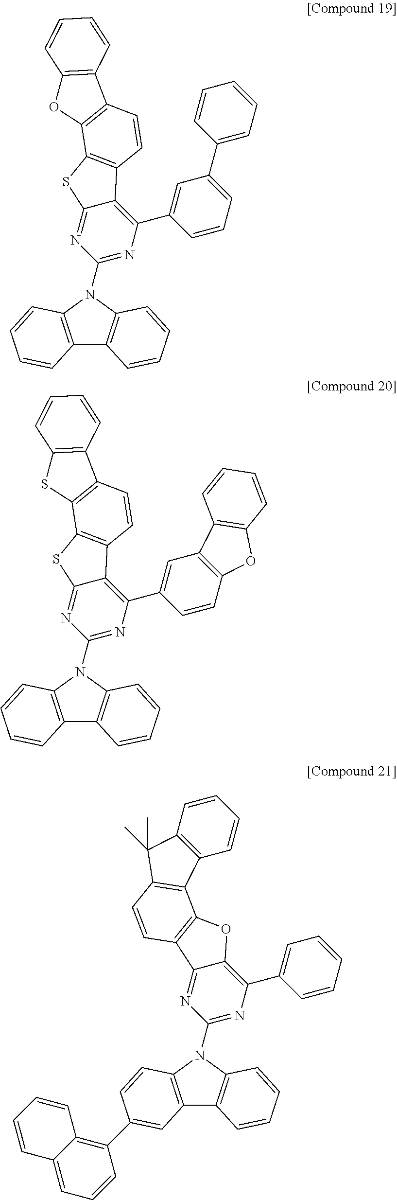


| TABLE 1 | |||||||
| Host | V | Cd/A | CIEx | CIEy | T95 (Hr) | ||
| C. Example 1 | CBP | 6.2 | 38 | 0.297 | 0.624 | 5 |
| Example 1 | Cpd. 1 | 4.3 | 56 | 0.339 | 0.628 | 85 |
| Example 2 | Cpd. 6 | 4.2 | 54 | 0.334 | 0.632 | 90 |
| Example 3 | Cpd. 13 | 4.3 | 56 | 0.335 | 0.631 | 80 |
| Example 4 | Cpd. 21 | 4.0 | 55 | 0.334 | 0.633 | 75 |
| Example 5 | Cpd. 33 | 4.1 | 57 | 0.333 | 0.632 | 80 |
| Example 6 | Cpd. 44 | 4.2 | 56 | 0.334 | 0.631 | 85 |
| Example 7 | Cpd. 52 | 4.3 | 53 | 0.335 | 0.631 | 75 |
| Example 8 | Cpd. 3 | 4.4 | 58 | 0.335 | 0.634 | 81 |
| Example 9 | Cpd. 92 | 4.2 | 56 | 0.333 | 0.632 | 88 |
| TABLE 2 | |||||||||
| T95 | |||||||||
| 2nd Host | 1st Host | Wt. Ratio of Hosts | V | Cd/A | CIEx | CIEy | (Hrs) | ||
| Example 10 | Cpd. 117 | Cpd. 85 | 5:5 | 4.0 | 57 | 0.337 | 0.628 | 170 |
| Example 11 | Cpd. 118 | Cpd. 93 | 5:5 | 3.9 | 55 | 0.322 | 0.629 | 160 |
| Example 12 | Cpd. 119 | Cpd. 101 | 5:5 | 3.9 | 56 | 0.330 | 0.626 | 190 |
| Example 13 | Cpd. 118 | Cpd. 44 | 3:7 | 4.4 | 61 | 0.339 | 0.633 | 207 |
| Example 14 | Cpd. 119 | Cpd. 92 | 7:3 | 3.8 | 53 | 0.331 | 0.628 | 151 |
| C. Example 2 | Cpd. 117 | 1 | 6.2 | 10.1 | 0.333 | 0.609 | 8 | |
| C. Example 3 | Cpd. 118 | 1 | 6.0 | 11.2 | 0.325 | 0.620 | 7 | |
| C. Example 4 | Cpd. 119 | 1 | 6.5 | 9.2 | 0.326 | 0.621 | 5 | |

| TABLE 3 | |||||||
| ETL | V | Cd/A | CIEx | CIEy | T95(Hrs) | ||
| C. Example 5 | ET | 4.3 | 6.5 | 0.133 | 0.129 | 10 |
| Example 15 | Cpd. 85 | 3.6 | 8.1 | 0.132 | 0.130 | 35 |
| Example 16 | Cpd. 93 | 3.7 | 8.2 | 0.133 | 0.128 | 32 |
| Example 17 | Cpd. 101 | 3.8 | 8.3 | 0.132 | 0.126 | 28 |
Claims (16)


Applications Claiming Priority (4)
| Application Number | Priority Date | Filing Date | Title |
|---|---|---|---|
| KR10-2016-0069742 | 2016-06-03 | ||
| KR20160069742 | 2016-06-03 | ||
| KR1020170053799A KR102418819B1 (en) | 2016-06-03 | 2017-04-26 | Novel heterocyclic compounds and organic light-emitting diode including the same |
| KR10-2017-0053799 | 2017-04-26 |
Publications (2)
| Publication Number | Publication Date |
|---|---|
| US20170352447A1 US20170352447A1 (en) | 2017-12-07 |
| US10529461B2 true US10529461B2 (en) | 2020-01-07 |
Family
ID=60483821
Family Applications (1)
| Application Number | Title | Priority Date | Filing Date |
|---|---|---|---|
| US15/607,756 Active 2038-01-02 US10529461B2 (en) | 2016-06-03 | 2017-05-30 | Heterocyclic compounds and organic light-emitting diode including the same |
Country Status (2)
| Country | Link |
|---|---|
| US (1) | US10529461B2 (en) |
| CN (1) | CN107459523B (en) |
Families Citing this family (8)
| Publication number | Priority date | Publication date | Assignee | Title |
|---|---|---|---|---|
| KR102643402B1 (en) | 2017-09-20 | 2024-03-07 | 가부시키가이샤 한도오따이 에네루기 켄큐쇼 | Organic compounds, light-emitting elements, light-emitting devices, electronic devices, and lighting devices |
| WO2019229583A1 (en) * | 2018-05-31 | 2019-12-05 | 株式会社半導体エネルギー研究所 | Organic compounds, light-emitting element, light-emitting device, electronic device, and illumination device |
| CN110563687B (en) * | 2019-07-23 | 2022-09-30 | 上海合全医药有限公司 | Preparation method of 4- (aminomethyl) chroman-3-ol |
| JP2023025302A (en) * | 2019-12-10 | 2023-02-22 | 出光興産株式会社 | Organic electroluminescence element, compound, and electronic device |
| EP4217440B1 (en) * | 2020-09-24 | 2024-05-29 | Merck Patent GmbH | Organic electroluminescent device |
| CN112174969B (en) * | 2020-10-30 | 2023-01-17 | 北京八亿时空液晶科技股份有限公司 | Organic compound, organic electroluminescent material and organic electroluminescent element |
| WO2022157599A1 (en) * | 2021-01-22 | 2022-07-28 | 株式会社半導体エネルギー研究所 | Organic compound, luminescent device, luminescent apparatus, electronic appliance, and illuminator |
| US20240431202A1 (en) | 2021-10-14 | 2024-12-26 | Merck Patent Gmbh | Materials for organic electroluminescent devices |
Citations (10)
| Publication number | Priority date | Publication date | Assignee | Title |
|---|---|---|---|---|
| JP2010166070A (en) | 2010-03-04 | 2010-07-29 | Konica Minolta Holdings Inc | Organic electroluminescent element and display |
| JP2010168363A (en) | 2008-12-25 | 2010-08-05 | Chisso Corp | Anthracene derivative having pyridylnaphthyl group and organic electroluminescent device |
| KR20110013220A (en) | 2009-07-31 | 2011-02-09 | 다우어드밴스드디스플레이머티리얼 유한회사 | Novel organic light emitting compound and organic electroluminescent device comprising same |
| WO2011149284A2 (en) | 2010-05-26 | 2011-12-01 | 덕산하이메탈(주) | Hetero-atom-containing compound in which carbazole and fluorene are fused, an organic electrical element using the same and a terminal thereof |
| US20120206035A1 (en) * | 2011-02-16 | 2012-08-16 | Semiconductor Energy Laboratory Co., Ltd. | Light-emitting element |
| KR20120104204A (en) | 2009-11-12 | 2012-09-20 | 호도가야 가가쿠 고교 가부시키가이샤 | Compound having a substituted anthracene ring structure and pyridoindole ring structure, and organic electroluminescent element |
| KR20130069413A (en) * | 2011-12-16 | 2013-06-26 | 주식회사 엘지화학 | New compound and organic light emitting device using the same |
| KR20130070431A (en) | 2011-12-19 | 2013-06-27 | 단국대학교 산학협력단 | Multicyclic aromatic compound and organic light emitting device including the same |
| CN104271700A (en) | 2012-04-03 | 2015-01-07 | 罗门哈斯电子材料韩国有限公司 | Novel organic electroluminescent compounds and organic electroluminescent device comprising the same |
| US20160351816A1 (en) * | 2015-05-27 | 2016-12-01 | Samsung Display Co., Ltd. | Organic light-emitting device |
Family Cites Families (3)
| Publication number | Priority date | Publication date | Assignee | Title |
|---|---|---|---|---|
| US8889271B2 (en) * | 2006-11-26 | 2014-11-18 | Duksan High Metal Co., Ltd. | Compound containing a 5-membered heterocycle and organic light-emitting diode using same, and terminal for same |
| JP2015065248A (en) * | 2013-09-24 | 2015-04-09 | 出光興産株式会社 | Organic electroluminescent element, and electronic device |
| JP2015106658A (en) * | 2013-11-29 | 2015-06-08 | 出光興産株式会社 | Organic electroluminescent element and electronic device |
-
2017
- 2017-05-30 US US15/607,756 patent/US10529461B2/en active Active
- 2017-05-31 CN CN201710398487.7A patent/CN107459523B/en active Active
Patent Citations (11)
| Publication number | Priority date | Publication date | Assignee | Title |
|---|---|---|---|---|
| JP2010168363A (en) | 2008-12-25 | 2010-08-05 | Chisso Corp | Anthracene derivative having pyridylnaphthyl group and organic electroluminescent device |
| KR20110013220A (en) | 2009-07-31 | 2011-02-09 | 다우어드밴스드디스플레이머티리얼 유한회사 | Novel organic light emitting compound and organic electroluminescent device comprising same |
| KR20120104204A (en) | 2009-11-12 | 2012-09-20 | 호도가야 가가쿠 고교 가부시키가이샤 | Compound having a substituted anthracene ring structure and pyridoindole ring structure, and organic electroluminescent element |
| JP2010166070A (en) | 2010-03-04 | 2010-07-29 | Konica Minolta Holdings Inc | Organic electroluminescent element and display |
| WO2011149284A2 (en) | 2010-05-26 | 2011-12-01 | 덕산하이메탈(주) | Hetero-atom-containing compound in which carbazole and fluorene are fused, an organic electrical element using the same and a terminal thereof |
| US20120206035A1 (en) * | 2011-02-16 | 2012-08-16 | Semiconductor Energy Laboratory Co., Ltd. | Light-emitting element |
| KR20130069413A (en) * | 2011-12-16 | 2013-06-26 | 주식회사 엘지화학 | New compound and organic light emitting device using the same |
| KR20130070431A (en) | 2011-12-19 | 2013-06-27 | 단국대학교 산학협력단 | Multicyclic aromatic compound and organic light emitting device including the same |
| CN104271700A (en) | 2012-04-03 | 2015-01-07 | 罗门哈斯电子材料韩国有限公司 | Novel organic electroluminescent compounds and organic electroluminescent device comprising the same |
| US20160351816A1 (en) * | 2015-05-27 | 2016-12-01 | Samsung Display Co., Ltd. | Organic light-emitting device |
| CN106206999A (en) | 2015-05-27 | 2016-12-07 | 三星显示有限公司 | organic light emitting device |
Non-Patent Citations (4)
| Title |
|---|
| Machine English translation of Lee et al. (KR 10-2013-0070431). Feb. 25, 2019. * |
| Machine English translation of Park et al. (KR 10-2013-0069413). Feb. 25, 2019. * |
| Office action from China National Intellectual Property Administration of 201710398487, dated Jan. 16, 2019. |
| Office Action from China National Intellectual Property Administration of 201710398487.7, dated Aug. 20, 2019. |
Also Published As
| Publication number | Publication date |
|---|---|
| CN107459523A (en) | 2017-12-12 |
| CN107459523B (en) | 2020-04-14 |
| US20170352447A1 (en) | 2017-12-07 |
Similar Documents
| Publication | Publication Date | Title |
|---|---|---|
| US20240279196A1 (en) | Organic compound and oranic light-emitting diode comprising same background of the invention | |
| US11133472B1 (en) | Organic light-emitting diode having long lifespan, low voltage, and high efficiency property | |
| US10947449B2 (en) | Organic light-emitting diode with high efficiency and long lifetime | |
| US10562876B2 (en) | Organic compounds for organic light-emitting diode and organic light-emitting diode including the same | |
| US20210184136A1 (en) | Organic light emitting diode for high efficiency | |
| US12010915B2 (en) | Organic light-emitting diode having long lifespan, low voltage, and high efficiency property | |
| US10468603B2 (en) | Organic light-emitting diode having low driving voltage and long lifespan | |
| US11672172B2 (en) | Heterocyclic compound comprising aromatic amine group and organic light-emitting diode including the same | |
| US11075343B2 (en) | Organic light emitting compounds and organic light emitting devices including the same | |
| US10529461B2 (en) | Heterocyclic compounds and organic light-emitting diode including the same | |
| US10014479B2 (en) | Organic light-emitting diode with high efficiency and long lifetime | |
| US11563181B2 (en) | Amine compounds for organic light-emitting diode and organic light-emitting diode including the same | |
| US11251378B2 (en) | Organic light-emitting diode having alleviated luminance reduction in low dynamic range | |
| US12415950B2 (en) | Boron compound and organic light emitting diode including same | |
| US11404647B2 (en) | Organic compound for organic light emitting diode and organic light emitting diode including same | |
| US20180351112A1 (en) | Novel organic light emitting compound and organic light emitting diode comprising same | |
| CN107001321B (en) | Compound and organic light emitting device including the same | |
| US12284917B2 (en) | Compound for organic light-emitting diode and organic light-emitting diode comprising same | |
| US20170222160A1 (en) | Organic light emitting compounds and organic light emitting devices including the same | |
| US12114562B2 (en) | Compound for organic light-emitting diode and long lifespan organic light-emitting diode comprising same | |
| CN112457844A (en) | Novel compound and organic light emitting device comprising the same | |
| US10526342B2 (en) | Organic heterocyclic compound and light-emitting device comprising same | |
| US20210057655A1 (en) | Organic light emitting compound and organic light emitting diode including the same | |
| KR20200139113A (en) | Novel organic compounds for organic light-emitting diode and organic light-emitting diode including the same | |
| US20250063948A1 (en) | High efficiency and long lifetime organic light-emitting diode |
Legal Events
| Date | Code | Title | Description |
|---|---|---|---|
| AS | Assignment |
Owner name: SFC CO., LTD., KOREA, REPUBLIC OF Free format text: ASSIGNMENT OF ASSIGNORS INTEREST;ASSIGNORS:LEE, SE-JIN;PARK, SEOK-BAE;YU, TAEJUNG;AND OTHERS;REEL/FRAME:042524/0700 Effective date: 20170516 |
|
| STPP | Information on status: patent application and granting procedure in general |
Free format text: NON FINAL ACTION MAILED |
|
| STPP | Information on status: patent application and granting procedure in general |
Free format text: RESPONSE TO NON-FINAL OFFICE ACTION ENTERED AND FORWARDED TO EXAMINER |
|
| STPP | Information on status: patent application and granting procedure in general |
Free format text: FINAL REJECTION MAILED |
|
| STPP | Information on status: patent application and granting procedure in general |
Free format text: NOTICE OF ALLOWANCE MAILED -- APPLICATION RECEIVED IN OFFICE OF PUBLICATIONS |
|
| STPP | Information on status: patent application and granting procedure in general |
Free format text: PUBLICATIONS -- ISSUE FEE PAYMENT VERIFIED |
|
| STCF | Information on status: patent grant |
Free format text: PATENTED CASE |
|
| MAFP | Maintenance fee payment |
Free format text: PAYMENT OF MAINTENANCE FEE, 4TH YR, SMALL ENTITY (ORIGINAL EVENT CODE: M2551); ENTITY STATUS OF PATENT OWNER: SMALL ENTITY Year of fee payment: 4 |