US10526342B2 - Organic heterocyclic compound and light-emitting device comprising same - Google Patents
Organic heterocyclic compound and light-emitting device comprising same Download PDFInfo
- Publication number
- US10526342B2 US10526342B2 US15/561,041 US201615561041A US10526342B2 US 10526342 B2 US10526342 B2 US 10526342B2 US 201615561041 A US201615561041 A US 201615561041A US 10526342 B2 US10526342 B2 US 10526342B2
- Authority
- US
- United States
- Prior art keywords
- carbon atoms
- substituted
- unsubstituted
- compound
- emitting
- Prior art date
- Legal status (The legal status is an assumption and is not a legal conclusion. Google has not performed a legal analysis and makes no representation as to the accuracy of the status listed.)
- Active, expires
Links
- 150000004395 organic heterocyclic compounds Chemical class 0.000 title 1
- 150000001875 compounds Chemical class 0.000 claims abstract description 50
- 239000000126 substance Substances 0.000 claims abstract description 28
- 230000015572 biosynthetic process Effects 0.000 claims description 181
- 125000004432 carbon atom Chemical group C* 0.000 claims description 149
- 239000010410 layer Substances 0.000 claims description 75
- 125000001424 substituent group Chemical group 0.000 claims description 31
- 239000012044 organic layer Substances 0.000 claims description 29
- 125000003118 aryl group Chemical group 0.000 claims description 25
- 238000002347 injection Methods 0.000 claims description 24
- 239000007924 injection Substances 0.000 claims description 24
- 125000000217 alkyl group Chemical group 0.000 claims description 20
- 125000001072 heteroaryl group Chemical group 0.000 claims description 19
- YNPNZTXNASCQKK-UHFFFAOYSA-N phenanthrene Chemical group C1=CC=C2C3=CC=CC=C3C=CC2=C1 YNPNZTXNASCQKK-UHFFFAOYSA-N 0.000 claims description 18
- 239000002019 doping agent Substances 0.000 claims description 16
- 230000005525 hole transport Effects 0.000 claims description 14
- 230000004888 barrier function Effects 0.000 claims description 13
- 125000004093 cyano group Chemical group *C#N 0.000 claims description 12
- 229910052805 deuterium Inorganic materials 0.000 claims description 12
- 150000002894 organic compounds Chemical class 0.000 claims description 12
- YZCKVEUIGOORGS-OUBTZVSYSA-N Deuterium Chemical compound [2H] YZCKVEUIGOORGS-OUBTZVSYSA-N 0.000 claims description 11
- 229910052736 halogen Inorganic materials 0.000 claims description 11
- 150000002367 halogens Chemical class 0.000 claims description 11
- 125000003545 alkoxy group Chemical group 0.000 claims description 10
- 125000003342 alkenyl group Chemical group 0.000 claims description 9
- 125000000753 cycloalkyl group Chemical group 0.000 claims description 9
- 125000000449 nitro group Chemical group [O-][N+](*)=O 0.000 claims description 9
- 229910052760 oxygen Inorganic materials 0.000 claims description 9
- 125000005103 alkyl silyl group Chemical group 0.000 claims description 8
- 125000005104 aryl silyl group Chemical group 0.000 claims description 8
- 229910052739 hydrogen Inorganic materials 0.000 claims description 8
- 239000001257 hydrogen Substances 0.000 claims description 8
- 125000000304 alkynyl group Chemical group 0.000 claims description 7
- 125000004104 aryloxy group Chemical group 0.000 claims description 7
- 150000002431 hydrogen Chemical class 0.000 claims description 7
- 229910052757 nitrogen Inorganic materials 0.000 claims description 7
- 125000005165 aryl thioxy group Chemical group 0.000 claims description 5
- 229940125904 compound 1 Drugs 0.000 claims description 5
- 125000000392 cycloalkenyl group Chemical group 0.000 claims description 5
- 229910052717 sulfur Inorganic materials 0.000 claims description 5
- 125000005377 alkyl thioxy group Chemical group 0.000 claims description 4
- 125000005842 heteroatom Chemical group 0.000 claims description 4
- 238000005286 illumination Methods 0.000 claims description 4
- 125000003710 aryl alkyl group Chemical group 0.000 claims description 3
- 125000004446 heteroarylalkyl group Chemical group 0.000 claims description 3
- 239000002346 layers by function Substances 0.000 claims description 2
- 229920006395 saturated elastomer Polymers 0.000 claims description 2
- GCTFTMWXZFLTRR-GFCCVEGCSA-N (2r)-2-amino-n-[3-(difluoromethoxy)-4-(1,3-oxazol-5-yl)phenyl]-4-methylpentanamide Chemical compound FC(F)OC1=CC(NC(=O)[C@H](N)CC(C)C)=CC=C1C1=CN=CO1 GCTFTMWXZFLTRR-GFCCVEGCSA-N 0.000 claims 1
- WWTBZEKOSBFBEM-SPWPXUSOSA-N (2s)-2-[[2-benzyl-3-[hydroxy-[(1r)-2-phenyl-1-(phenylmethoxycarbonylamino)ethyl]phosphoryl]propanoyl]amino]-3-(1h-indol-3-yl)propanoic acid Chemical compound N([C@@H](CC=1C2=CC=CC=C2NC=1)C(=O)O)C(=O)C(CP(O)(=O)[C@H](CC=1C=CC=CC=1)NC(=O)OCC=1C=CC=CC=1)CC1=CC=CC=C1 WWTBZEKOSBFBEM-SPWPXUSOSA-N 0.000 claims 1
- STBLNCCBQMHSRC-BATDWUPUSA-N (2s)-n-[(3s,4s)-5-acetyl-7-cyano-4-methyl-1-[(2-methylnaphthalen-1-yl)methyl]-2-oxo-3,4-dihydro-1,5-benzodiazepin-3-yl]-2-(methylamino)propanamide Chemical compound O=C1[C@@H](NC(=O)[C@H](C)NC)[C@H](C)N(C(C)=O)C2=CC(C#N)=CC=C2N1CC1=C(C)C=CC2=CC=CC=C12 STBLNCCBQMHSRC-BATDWUPUSA-N 0.000 claims 1
- IWZSHWBGHQBIML-ZGGLMWTQSA-N (3S,8S,10R,13S,14S,17S)-17-isoquinolin-7-yl-N,N,10,13-tetramethyl-2,3,4,7,8,9,11,12,14,15,16,17-dodecahydro-1H-cyclopenta[a]phenanthren-3-amine Chemical compound CN(C)[C@H]1CC[C@]2(C)C3CC[C@@]4(C)[C@@H](CC[C@@H]4c4ccc5ccncc5c4)[C@@H]3CC=C2C1 IWZSHWBGHQBIML-ZGGLMWTQSA-N 0.000 claims 1
- MHSLDASSAFCCDO-UHFFFAOYSA-N 1-(5-tert-butyl-2-methylpyrazol-3-yl)-3-(4-pyridin-4-yloxyphenyl)urea Chemical compound CN1N=C(C(C)(C)C)C=C1NC(=O)NC(C=C1)=CC=C1OC1=CC=NC=C1 MHSLDASSAFCCDO-UHFFFAOYSA-N 0.000 claims 1
- ONBQEOIKXPHGMB-VBSBHUPXSA-N 1-[2-[(2s,3r,4s,5r)-3,4-dihydroxy-5-(hydroxymethyl)oxolan-2-yl]oxy-4,6-dihydroxyphenyl]-3-(4-hydroxyphenyl)propan-1-one Chemical compound O[C@@H]1[C@H](O)[C@@H](CO)O[C@H]1OC1=CC(O)=CC(O)=C1C(=O)CCC1=CC=C(O)C=C1 ONBQEOIKXPHGMB-VBSBHUPXSA-N 0.000 claims 1
- MPMKMQHJHDHPBE-RUZDIDTESA-N 4-[[(2r)-1-(1-benzothiophene-3-carbonyl)-2-methylazetidine-2-carbonyl]-[(3-chlorophenyl)methyl]amino]butanoic acid Chemical compound O=C([C@@]1(N(CC1)C(=O)C=1C2=CC=CC=C2SC=1)C)N(CCCC(O)=O)CC1=CC=CC(Cl)=C1 MPMKMQHJHDHPBE-RUZDIDTESA-N 0.000 claims 1
- ISMDILRWKSYCOD-GNKBHMEESA-N C(C1=CC=CC=C1)[C@@H]1NC(OCCCCCCCCCCCNC([C@@H](NC(C[C@@H]1O)=O)C(C)C)=O)=O Chemical compound C(C1=CC=CC=C1)[C@@H]1NC(OCCCCCCCCCCCNC([C@@H](NC(C[C@@H]1O)=O)C(C)C)=O)=O ISMDILRWKSYCOD-GNKBHMEESA-N 0.000 claims 1
- 229940126639 Compound 33 Drugs 0.000 claims 1
- LNUFLCYMSVYYNW-ZPJMAFJPSA-N [(2r,3r,4s,5r,6r)-2-[(2r,3r,4s,5r,6r)-6-[(2r,3r,4s,5r,6r)-6-[(2r,3r,4s,5r,6r)-6-[[(3s,5s,8r,9s,10s,13r,14s,17r)-10,13-dimethyl-17-[(2r)-6-methylheptan-2-yl]-2,3,4,5,6,7,8,9,11,12,14,15,16,17-tetradecahydro-1h-cyclopenta[a]phenanthren-3-yl]oxy]-4,5-disulfo Chemical compound O([C@@H]1[C@@H](COS(O)(=O)=O)O[C@@H]([C@@H]([C@H]1OS(O)(=O)=O)OS(O)(=O)=O)O[C@@H]1[C@@H](COS(O)(=O)=O)O[C@@H]([C@@H]([C@H]1OS(O)(=O)=O)OS(O)(=O)=O)O[C@@H]1[C@@H](COS(O)(=O)=O)O[C@H]([C@@H]([C@H]1OS(O)(=O)=O)OS(O)(=O)=O)O[C@@H]1C[C@@H]2CC[C@H]3[C@@H]4CC[C@@H]([C@]4(CC[C@@H]3[C@@]2(C)CC1)C)[C@H](C)CCCC(C)C)[C@H]1O[C@H](COS(O)(=O)=O)[C@@H](OS(O)(=O)=O)[C@H](OS(O)(=O)=O)[C@H]1OS(O)(=O)=O LNUFLCYMSVYYNW-ZPJMAFJPSA-N 0.000 claims 1
- 229940126142 compound 16 Drugs 0.000 claims 1
- 229940126208 compound 22 Drugs 0.000 claims 1
- 229940125878 compound 36 Drugs 0.000 claims 1
- 229940125900 compound 59 Drugs 0.000 claims 1
- YGBMCLDVRUGXOV-UHFFFAOYSA-N n-[6-[6-chloro-5-[(4-fluorophenyl)sulfonylamino]pyridin-3-yl]-1,3-benzothiazol-2-yl]acetamide Chemical compound C1=C2SC(NC(=O)C)=NC2=CC=C1C(C=1)=CN=C(Cl)C=1NS(=O)(=O)C1=CC=C(F)C=C1 YGBMCLDVRUGXOV-UHFFFAOYSA-N 0.000 claims 1
- 238000003786 synthesis reaction Methods 0.000 description 170
- 238000006243 chemical reaction Methods 0.000 description 130
- 238000000034 method Methods 0.000 description 65
- 239000000463 material Substances 0.000 description 47
- 0 C.[1*]C1=C(CC)C(C)=C([4*])C([3*])=C1[2*].[11*]C1=C([12*])C([13*])=C([14*])C2=C1C([20*])=C([19*])C1=C2C([15*])=C([16*])C([17*])=C1[18*].[5*]C1=C([6*])C([7*])=C([8*])C([Y]C)=C1C Chemical compound C.[1*]C1=C(CC)C(C)=C([4*])C([3*])=C1[2*].[11*]C1=C([12*])C([13*])=C([14*])C2=C1C([20*])=C([19*])C1=C2C([15*])=C([16*])C([17*])=C1[18*].[5*]C1=C([6*])C([7*])=C([8*])C([Y]C)=C1C 0.000 description 25
- IYYZUPMFVPLQIF-UHFFFAOYSA-N dibenzothiophene Chemical compound C1=CC=C2C3=CC=CC=C3SC2=C1 IYYZUPMFVPLQIF-UHFFFAOYSA-N 0.000 description 22
- YXFVVABEGXRONW-UHFFFAOYSA-N Toluene Chemical compound CC1=CC=CC=C1 YXFVVABEGXRONW-UHFFFAOYSA-N 0.000 description 18
- 238000004440 column chromatography Methods 0.000 description 18
- 238000000746 purification Methods 0.000 description 17
- WYURNTSHIVDZCO-UHFFFAOYSA-N Tetrahydrofuran Chemical compound C1CCOC1 WYURNTSHIVDZCO-UHFFFAOYSA-N 0.000 description 16
- 238000001840 matrix-assisted laser desorption--ionisation time-of-flight mass spectrometry Methods 0.000 description 15
- 239000011541 reaction mixture Substances 0.000 description 12
- 239000000243 solution Substances 0.000 description 12
- ZMXDDKWLCZADIW-UHFFFAOYSA-N N,N-Dimethylformamide Chemical compound CN(C)C=O ZMXDDKWLCZADIW-UHFFFAOYSA-N 0.000 description 11
- 238000010586 diagram Methods 0.000 description 11
- -1 methoxy, ethoxy, propoxy, isobutyloxy, sec-butyloxy, pentyloxy, iso-amyloxy Chemical group 0.000 description 11
- 150000003254 radicals Chemical group 0.000 description 11
- UFVXQDWNSAGPHN-UHFFFAOYSA-K bis[(2-methylquinolin-8-yl)oxy]-(4-phenylphenoxy)alumane Chemical compound [Al+3].C1=CC=C([O-])C2=NC(C)=CC=C21.C1=CC=C([O-])C2=NC(C)=CC=C21.C1=CC([O-])=CC=C1C1=CC=CC=C1 UFVXQDWNSAGPHN-UHFFFAOYSA-K 0.000 description 10
- YMWUJEATGCHHMB-UHFFFAOYSA-N Dichloromethane Chemical compound ClCCl YMWUJEATGCHHMB-UHFFFAOYSA-N 0.000 description 9
- OKKJLVBELUTLKV-UHFFFAOYSA-N Methanol Chemical compound OC OKKJLVBELUTLKV-UHFFFAOYSA-N 0.000 description 9
- NFHFRUOZVGFOOS-UHFFFAOYSA-N palladium;triphenylphosphane Chemical compound [Pd].C1=CC=CC=C1P(C=1C=CC=CC=1)C1=CC=CC=C1.C1=CC=CC=C1P(C=1C=CC=CC=1)C1=CC=CC=C1.C1=CC=CC=C1P(C=1C=CC=CC=1)C1=CC=CC=C1.C1=CC=CC=C1P(C=1C=CC=CC=1)C1=CC=CC=C1 NFHFRUOZVGFOOS-UHFFFAOYSA-N 0.000 description 8
- 238000003756 stirring Methods 0.000 description 8
- YLQBMQCUIZJEEH-UHFFFAOYSA-N tetrahydrofuran Natural products C=1C=COC=1 YLQBMQCUIZJEEH-UHFFFAOYSA-N 0.000 description 8
- 239000000758 substrate Substances 0.000 description 7
- PCLIMKBDDGJMGD-UHFFFAOYSA-N N-bromosuccinimide Chemical compound BrN1C(=O)CCC1=O PCLIMKBDDGJMGD-UHFFFAOYSA-N 0.000 description 6
- HEMHJVSKTPXQMS-UHFFFAOYSA-M Sodium hydroxide Chemical compound [OH-].[Na+] HEMHJVSKTPXQMS-UHFFFAOYSA-M 0.000 description 6
- TXCDCPKCNAJMEE-UHFFFAOYSA-N dibenzofuran Chemical compound C1=CC=C2C3=CC=CC=C3OC2=C1 TXCDCPKCNAJMEE-UHFFFAOYSA-N 0.000 description 6
- 125000004435 hydrogen atom Chemical group [H]* 0.000 description 6
- VLKZOEOYAKHREP-UHFFFAOYSA-N n-Hexane Chemical compound CCCCCC VLKZOEOYAKHREP-UHFFFAOYSA-N 0.000 description 6
- 239000012299 nitrogen atmosphere Substances 0.000 description 6
- BWHMMNNQKKPAPP-UHFFFAOYSA-L potassium carbonate Chemical compound [K+].[K+].[O-]C([O-])=O BWHMMNNQKKPAPP-UHFFFAOYSA-L 0.000 description 6
- XLYOFNOQVPJJNP-UHFFFAOYSA-N water Chemical compound O XLYOFNOQVPJJNP-UHFFFAOYSA-N 0.000 description 6
- 125000003282 alkyl amino group Chemical group 0.000 description 5
- 239000012153 distilled water Substances 0.000 description 5
- 238000004528 spin coating Methods 0.000 description 5
- HEDRZPFGACZZDS-UHFFFAOYSA-N Chloroform Chemical compound ClC(Cl)Cl HEDRZPFGACZZDS-UHFFFAOYSA-N 0.000 description 4
- MZRVEZGGRBJDDB-UHFFFAOYSA-N N-Butyllithium Chemical compound [Li]CCCC MZRVEZGGRBJDDB-UHFFFAOYSA-N 0.000 description 4
- 229910052782 aluminium Inorganic materials 0.000 description 4
- XAGFODPZIPBFFR-UHFFFAOYSA-N aluminium Chemical compound [Al] XAGFODPZIPBFFR-UHFFFAOYSA-N 0.000 description 4
- 125000001769 aryl amino group Chemical group 0.000 description 4
- 125000004429 atom Chemical group 0.000 description 4
- 238000001914 filtration Methods 0.000 description 4
- 238000004020 luminiscence type Methods 0.000 description 4
- 238000004519 manufacturing process Methods 0.000 description 4
- 125000001181 organosilyl group Chemical group [SiH3]* 0.000 description 4
- HXITXNWTGFUOAU-UHFFFAOYSA-N phenylboronic acid Chemical compound OB(O)C1=CC=CC=C1 HXITXNWTGFUOAU-UHFFFAOYSA-N 0.000 description 4
- SCVFZCLFOSHCOH-UHFFFAOYSA-M potassium acetate Chemical compound [K+].CC([O-])=O SCVFZCLFOSHCOH-UHFFFAOYSA-M 0.000 description 4
- MFRIHAYPQRLWNB-UHFFFAOYSA-N sodium tert-butoxide Chemical compound [Na+].CC(C)(C)[O-] MFRIHAYPQRLWNB-UHFFFAOYSA-N 0.000 description 4
- 239000007787 solid Substances 0.000 description 4
- GHYOCDFICYLMRF-UTIIJYGPSA-N (2S,3R)-N-[(2S)-3-(cyclopenten-1-yl)-1-[(2R)-2-methyloxiran-2-yl]-1-oxopropan-2-yl]-3-hydroxy-3-(4-methoxyphenyl)-2-[[(2S)-2-[(2-morpholin-4-ylacetyl)amino]propanoyl]amino]propanamide Chemical compound C1(=CCCC1)C[C@@H](C(=O)[C@@]1(OC1)C)NC([C@H]([C@@H](C1=CC=C(C=C1)OC)O)NC([C@H](C)NC(CN1CCOCC1)=O)=O)=O GHYOCDFICYLMRF-UTIIJYGPSA-N 0.000 description 3
- DEVSOMFAQLZNKR-RJRFIUFISA-N (z)-3-[3-[3,5-bis(trifluoromethyl)phenyl]-1,2,4-triazol-1-yl]-n'-pyrazin-2-ylprop-2-enehydrazide Chemical compound FC(F)(F)C1=CC(C(F)(F)F)=CC(C2=NN(\C=C/C(=O)NNC=3N=CC=NC=3)C=N2)=C1 DEVSOMFAQLZNKR-RJRFIUFISA-N 0.000 description 3
- VCUXVXLUOHDHKK-UHFFFAOYSA-N 2-(2-aminopyrimidin-4-yl)-4-(2-chloro-4-methoxyphenyl)-1,3-thiazole-5-carboxamide Chemical compound ClC1=CC(OC)=CC=C1C1=C(C(N)=O)SC(C=2N=C(N)N=CC=2)=N1 VCUXVXLUOHDHKK-UHFFFAOYSA-N 0.000 description 3
- PYRKKGOKRMZEIT-UHFFFAOYSA-N 2-[6-(2-cyclopropylethoxy)-9-(2-hydroxy-2-methylpropyl)-1h-phenanthro[9,10-d]imidazol-2-yl]-5-fluorobenzene-1,3-dicarbonitrile Chemical compound C1=C2C3=CC(CC(C)(O)C)=CC=C3C=3NC(C=4C(=CC(F)=CC=4C#N)C#N)=NC=3C2=CC=C1OCCC1CC1 PYRKKGOKRMZEIT-UHFFFAOYSA-N 0.000 description 3
- VVCMGAUPZIKYTH-VGHSCWAPSA-N 2-acetyloxybenzoic acid;[(2s,3r)-4-(dimethylamino)-3-methyl-1,2-diphenylbutan-2-yl] propanoate;1,3,7-trimethylpurine-2,6-dione Chemical compound CC(=O)OC1=CC=CC=C1C(O)=O.CN1C(=O)N(C)C(=O)C2=C1N=CN2C.C([C@](OC(=O)CC)([C@H](C)CN(C)C)C=1C=CC=CC=1)C1=CC=CC=C1 VVCMGAUPZIKYTH-VGHSCWAPSA-N 0.000 description 3
- MINMDCMSHDBHKG-UHFFFAOYSA-N 4-[4-[[6-methoxy-2-(2-methoxyimidazo[2,1-b][1,3,4]thiadiazol-6-yl)-1-benzofuran-4-yl]oxymethyl]-5-methyl-1,3-thiazol-2-yl]morpholine Chemical compound N1=C2SC(OC)=NN2C=C1C(OC1=CC(OC)=C2)=CC1=C2OCC(=C(S1)C)N=C1N1CCOCC1 MINMDCMSHDBHKG-UHFFFAOYSA-N 0.000 description 3
- WEVYAHXRMPXWCK-UHFFFAOYSA-N Acetonitrile Chemical compound CC#N WEVYAHXRMPXWCK-UHFFFAOYSA-N 0.000 description 3
- ZOXJGFHDIHLPTG-UHFFFAOYSA-N Boron Chemical compound [B] ZOXJGFHDIHLPTG-UHFFFAOYSA-N 0.000 description 3
- XEKOWRVHYACXOJ-UHFFFAOYSA-N Ethyl acetate Chemical compound CCOC(C)=O XEKOWRVHYACXOJ-UHFFFAOYSA-N 0.000 description 3
- KWYUFKZDYYNOTN-UHFFFAOYSA-M Potassium hydroxide Chemical compound [OH-].[K+] KWYUFKZDYYNOTN-UHFFFAOYSA-M 0.000 description 3
- LJOOWESTVASNOG-UFJKPHDISA-N [(1s,3r,4ar,7s,8s,8as)-3-hydroxy-8-[2-[(4r)-4-hydroxy-6-oxooxan-2-yl]ethyl]-7-methyl-1,2,3,4,4a,7,8,8a-octahydronaphthalen-1-yl] (2s)-2-methylbutanoate Chemical compound C([C@H]1[C@@H](C)C=C[C@H]2C[C@@H](O)C[C@@H]([C@H]12)OC(=O)[C@@H](C)CC)CC1C[C@@H](O)CC(=O)O1 LJOOWESTVASNOG-UFJKPHDISA-N 0.000 description 3
- SPXSEZMVRJLHQG-XMMPIXPASA-N [(2R)-1-[[4-[(3-phenylmethoxyphenoxy)methyl]phenyl]methyl]pyrrolidin-2-yl]methanol Chemical compound C(C1=CC=CC=C1)OC=1C=C(OCC2=CC=C(CN3[C@H](CCC3)CO)C=C2)C=CC=1 SPXSEZMVRJLHQG-XMMPIXPASA-N 0.000 description 3
- 125000002947 alkylene group Chemical group 0.000 description 3
- 150000005840 aryl radicals Chemical class 0.000 description 3
- 229910052796 boron Inorganic materials 0.000 description 3
- 229940125797 compound 12 Drugs 0.000 description 3
- 229940127204 compound 29 Drugs 0.000 description 3
- 229940127271 compound 49 Drugs 0.000 description 3
- GWNFQAKCJYEJEW-UHFFFAOYSA-N ethyl 3-[8-[[4-methyl-5-[(3-methyl-4-oxophthalazin-1-yl)methyl]-1,2,4-triazol-3-yl]sulfanyl]octanoylamino]benzoate Chemical compound CCOC(=O)C1=CC(NC(=O)CCCCCCCSC2=NN=C(CC3=NN(C)C(=O)C4=CC=CC=C34)N2C)=CC=C1 GWNFQAKCJYEJEW-UHFFFAOYSA-N 0.000 description 3
- 239000000706 filtrate Substances 0.000 description 3
- 239000011521 glass Substances 0.000 description 3
- 150000002391 heterocyclic compounds Chemical class 0.000 description 3
- 125000002887 hydroxy group Chemical group [H]O* 0.000 description 3
- 239000003446 ligand Substances 0.000 description 3
- 239000011368 organic material Substances 0.000 description 3
- 229910000027 potassium carbonate Inorganic materials 0.000 description 3
- 230000008569 process Effects 0.000 description 3
- 238000002207 thermal evaporation Methods 0.000 description 3
- XOLBLPGZBRYERU-UHFFFAOYSA-N tin dioxide Chemical compound O=[Sn]=O XOLBLPGZBRYERU-UHFFFAOYSA-N 0.000 description 3
- CYPYTURSJDMMMP-WVCUSYJESA-N (1e,4e)-1,5-diphenylpenta-1,4-dien-3-one;palladium Chemical compound [Pd].[Pd].C=1C=CC=CC=1\C=C\C(=O)\C=C\C1=CC=CC=C1.C=1C=CC=CC=1\C=C\C(=O)\C=C\C1=CC=CC=C1.C=1C=CC=CC=1\C=C\C(=O)\C=C\C1=CC=CC=C1 CYPYTURSJDMMMP-WVCUSYJESA-N 0.000 description 2
- STPKWKPURVSAJF-LJEWAXOPSA-N (4r,5r)-5-[4-[[4-(1-aza-4-azoniabicyclo[2.2.2]octan-4-ylmethyl)phenyl]methoxy]phenyl]-3,3-dibutyl-7-(dimethylamino)-1,1-dioxo-4,5-dihydro-2h-1$l^{6}-benzothiepin-4-ol Chemical compound O[C@H]1C(CCCC)(CCCC)CS(=O)(=O)C2=CC=C(N(C)C)C=C2[C@H]1C(C=C1)=CC=C1OCC(C=C1)=CC=C1C[N+]1(CC2)CCN2CC1 STPKWKPURVSAJF-LJEWAXOPSA-N 0.000 description 2
- WSLDOOZREJYCGB-UHFFFAOYSA-N 1,2-Dichloroethane Chemical compound ClCCCl WSLDOOZREJYCGB-UHFFFAOYSA-N 0.000 description 2
- RYHBNJHYFVUHQT-UHFFFAOYSA-N 1,4-Dioxane Chemical compound C1COCCO1 RYHBNJHYFVUHQT-UHFFFAOYSA-N 0.000 description 2
- SPDPTFAJSFKAMT-UHFFFAOYSA-N 1-n-[4-[4-(n-[4-(3-methyl-n-(3-methylphenyl)anilino)phenyl]anilino)phenyl]phenyl]-4-n,4-n-bis(3-methylphenyl)-1-n-phenylbenzene-1,4-diamine Chemical compound CC1=CC=CC(N(C=2C=CC(=CC=2)N(C=2C=CC=CC=2)C=2C=CC(=CC=2)C=2C=CC(=CC=2)N(C=2C=CC=CC=2)C=2C=CC(=CC=2)N(C=2C=C(C)C=CC=2)C=2C=C(C)C=CC=2)C=2C=C(C)C=CC=2)=C1 SPDPTFAJSFKAMT-UHFFFAOYSA-N 0.000 description 2
- BQBXKWGMPUCSQV-UHFFFAOYSA-N 2,5-dibromobenzaldehyde Chemical compound BrC1=CC=C(Br)C(C=O)=C1 BQBXKWGMPUCSQV-UHFFFAOYSA-N 0.000 description 2
- GEQBRULPNIVQPP-UHFFFAOYSA-N 2-[3,5-bis(1-phenylbenzimidazol-2-yl)phenyl]-1-phenylbenzimidazole Chemical compound C1=CC=CC=C1N1C2=CC=CC=C2N=C1C1=CC(C=2N(C3=CC=CC=C3N=2)C=2C=CC=CC=2)=CC(C=2N(C3=CC=CC=C3N=2)C=2C=CC=CC=2)=C1 GEQBRULPNIVQPP-UHFFFAOYSA-N 0.000 description 2
- HLCPWBZNUKCSBN-UHFFFAOYSA-N 2-aminobenzonitrile Chemical compound NC1=CC=CC=C1C#N HLCPWBZNUKCSBN-UHFFFAOYSA-N 0.000 description 2
- MBHPOBSZPYEADG-UHFFFAOYSA-N 2-bromo-9,9-dimethylfluorene Chemical compound C1=C(Br)C=C2C(C)(C)C3=CC=CC=C3C2=C1 MBHPOBSZPYEADG-UHFFFAOYSA-N 0.000 description 2
- OGGKVJMNFFSDEV-UHFFFAOYSA-N 3-methyl-n-[4-[4-(n-(3-methylphenyl)anilino)phenyl]phenyl]-n-phenylaniline Chemical compound CC1=CC=CC(N(C=2C=CC=CC=2)C=2C=CC(=CC=2)C=2C=CC(=CC=2)N(C=2C=CC=CC=2)C=2C=C(C)C=CC=2)=C1 OGGKVJMNFFSDEV-UHFFFAOYSA-N 0.000 description 2
- UJOBWOGCFQCDNV-UHFFFAOYSA-N 9H-carbazole Chemical compound C1=CC=C2C3=CC=CC=C3NC2=C1 UJOBWOGCFQCDNV-UHFFFAOYSA-N 0.000 description 2
- IOVDUISJESZHKY-UHFFFAOYSA-N Brc1c(ccc(c2c3)cc4c3c(cccc3)c3[n]4-c3ccccc3)c2ccc1 Chemical compound Brc1c(ccc(c2c3)cc4c3c(cccc3)c3[n]4-c3ccccc3)c2ccc1 IOVDUISJESZHKY-UHFFFAOYSA-N 0.000 description 2
- WKBOTKDWSSQWDR-UHFFFAOYSA-N Bromine atom Chemical compound [Br] WKBOTKDWSSQWDR-UHFFFAOYSA-N 0.000 description 2
- ZDYBMWZVZJCRHT-UHFFFAOYSA-N C1=CC=C(C2=C3C(=NC(N4C5=C(C=CC=C5)C5=C4C4=C(C=C5)C5=C(C=C4)C4=C(C=C5)C5=C(C=CC=C5)S4)=N2)C=CC2=C3C=CC=C2)C=C1.C1=CC=C(C2=C3C=C4C=CC=CC4=CC3=NC(N3C4=C(C=CC=C4)C4=C3C3=C(C=C4)C4=C(C=C3)C3=C(C=C4)C4=C(C=CC=C4)S3)=N2)C=C1.C1=CC=C(C2=C3C=CC4=C(C=CC=C4)C3=NC(N3C4=C(C=CC=C4)C4=C3C3=C(C=C4)C4=C(C=C3)C3=C(C=C4)C4=C(C=CC=C4)S3)=N2)C=C1.C[Si](C)(C)C1=CC=C(C2=C3C=CC=CC3=NC(N3C4=C(C=CC=C4)C4=C3C3=C(C=C4)C4=C(C=C3)C3=C(C=C4)C4=C(C=CC=C4)S3)=N2)C=C1 Chemical compound C1=CC=C(C2=C3C(=NC(N4C5=C(C=CC=C5)C5=C4C4=C(C=C5)C5=C(C=C4)C4=C(C=C5)C5=C(C=CC=C5)S4)=N2)C=CC2=C3C=CC=C2)C=C1.C1=CC=C(C2=C3C=C4C=CC=CC4=CC3=NC(N3C4=C(C=CC=C4)C4=C3C3=C(C=C4)C4=C(C=C3)C3=C(C=C4)C4=C(C=CC=C4)S3)=N2)C=C1.C1=CC=C(C2=C3C=CC4=C(C=CC=C4)C3=NC(N3C4=C(C=CC=C4)C4=C3C3=C(C=C4)C4=C(C=C3)C3=C(C=C4)C4=C(C=CC=C4)S3)=N2)C=C1.C[Si](C)(C)C1=CC=C(C2=C3C=CC=CC3=NC(N3C4=C(C=CC=C4)C4=C3C3=C(C=C4)C4=C(C=C3)C3=C(C=C4)C4=C(C=CC=C4)S3)=N2)C=C1 ZDYBMWZVZJCRHT-UHFFFAOYSA-N 0.000 description 2
- ZTXSAIHTFNEALM-UHFFFAOYSA-N C1=CC=C(C2=CC3=C(C4=CC=CC=C4)N=C(N4C5=C(C=CC=C5)C5=C4C4=C(SC6=C4C=CC=C6)C4=C5C5=C(C=CC=C5)C=C4)N=C3C=C2)C=C1.C1=CC=C(C2=CC3=C(C=C2)N=C(N2C4=C(C=CC=C4)C4=C2C2=C(C=C4)C4=C(C=C2)C=CC2=C4SC4=C2/C=C\C=C/4)N=C3C2=CC=CC=C2)C=C1.C1=CC=C(C2=CC3=C(C=C2)N=C(N2C4=C(C=CC=C4)C4=C2C=CC2=C4C=CC4=C2C2=C(C=C4)C4=CC=CC=C4S2)N=C3C2=CC=CC=C2)C=C1 Chemical compound C1=CC=C(C2=CC3=C(C4=CC=CC=C4)N=C(N4C5=C(C=CC=C5)C5=C4C4=C(SC6=C4C=CC=C6)C4=C5C5=C(C=CC=C5)C=C4)N=C3C=C2)C=C1.C1=CC=C(C2=CC3=C(C=C2)N=C(N2C4=C(C=CC=C4)C4=C2C2=C(C=C4)C4=C(C=C2)C=CC2=C4SC4=C2/C=C\C=C/4)N=C3C2=CC=CC=C2)C=C1.C1=CC=C(C2=CC3=C(C=C2)N=C(N2C4=C(C=CC=C4)C4=C2C=CC2=C4C=CC4=C2C2=C(C=C4)C4=CC=CC=C4S2)N=C3C2=CC=CC=C2)C=C1 ZTXSAIHTFNEALM-UHFFFAOYSA-N 0.000 description 2
- VJKMKYNORCTZLW-UHFFFAOYSA-N C1=CC=C(N2C3=CC=CC=C3C3=C2C=C2/C=C\C4=C(C=CC5=C4NC4=CC=CC=C45)C2=C3)C=C1 Chemical compound C1=CC=C(N2C3=CC=CC=C3C3=C2C=C2/C=C\C4=C(C=CC5=C4NC4=CC=CC=C45)C2=C3)C=C1 VJKMKYNORCTZLW-UHFFFAOYSA-N 0.000 description 2
- CZUKKSDWDSRTTC-UHFFFAOYSA-N CC1(C)C2=CC=CC=C2C2=C1C=C1C(=C2)C=CC2=C1C=CC1=C2C2=CC=CC=C2N1 Chemical compound CC1(C)C2=CC=CC=C2C2=C1C=C1C(=C2)C=CC2=C1C=CC1=C2C2=CC=CC=C2N1 CZUKKSDWDSRTTC-UHFFFAOYSA-N 0.000 description 2
- OAKJQQAXSVQMHS-UHFFFAOYSA-N Hydrazine Chemical compound NN OAKJQQAXSVQMHS-UHFFFAOYSA-N 0.000 description 2
- NBIIXXVUZAFLBC-UHFFFAOYSA-N Phosphoric acid Chemical compound OP(O)(O)=O NBIIXXVUZAFLBC-UHFFFAOYSA-N 0.000 description 2
- QAOWNCQODCNURD-UHFFFAOYSA-N Sulfuric acid Chemical compound OS(O)(=O)=O QAOWNCQODCNURD-UHFFFAOYSA-N 0.000 description 2
- 239000007983 Tris buffer Substances 0.000 description 2
- 229910052783 alkali metal Inorganic materials 0.000 description 2
- 150000001340 alkali metals Chemical class 0.000 description 2
- 229910052784 alkaline earth metal Inorganic materials 0.000 description 2
- 150000001342 alkaline earth metals Chemical class 0.000 description 2
- 125000004450 alkenylene group Chemical group 0.000 description 2
- 150000003973 alkyl amines Chemical class 0.000 description 2
- 150000004982 aromatic amines Chemical class 0.000 description 2
- GDTBXPJZTBHREO-UHFFFAOYSA-N bromine Substances BrBr GDTBXPJZTBHREO-UHFFFAOYSA-N 0.000 description 2
- 229910052794 bromium Inorganic materials 0.000 description 2
- 239000011575 calcium Substances 0.000 description 2
- 229910052799 carbon Inorganic materials 0.000 description 2
- 230000000052 comparative effect Effects 0.000 description 2
- 229940126214 compound 3 Drugs 0.000 description 2
- 238000005137 deposition process Methods 0.000 description 2
- ZUOUZKKEUPVFJK-UHFFFAOYSA-N diphenyl Chemical compound C1=CC=CC=C1C1=CC=CC=C1 ZUOUZKKEUPVFJK-UHFFFAOYSA-N 0.000 description 2
- 239000007772 electrode material Substances 0.000 description 2
- 229910052732 germanium Inorganic materials 0.000 description 2
- 230000005283 ground state Effects 0.000 description 2
- 125000004404 heteroalkyl group Chemical group 0.000 description 2
- 125000005241 heteroarylamino group Chemical group 0.000 description 2
- 125000000592 heterocycloalkyl group Chemical group 0.000 description 2
- 238000004770 highest occupied molecular orbital Methods 0.000 description 2
- 239000011777 magnesium Substances 0.000 description 2
- 230000007246 mechanism Effects 0.000 description 2
- 229910052751 metal Inorganic materials 0.000 description 2
- 239000002184 metal Substances 0.000 description 2
- 150000002736 metal compounds Chemical class 0.000 description 2
- 125000002950 monocyclic group Chemical group 0.000 description 2
- IBHBKWKFFTZAHE-UHFFFAOYSA-N n-[4-[4-(n-naphthalen-1-ylanilino)phenyl]phenyl]-n-phenylnaphthalen-1-amine Chemical compound C1=CC=CC=C1N(C=1C2=CC=CC=C2C=CC=1)C1=CC=C(C=2C=CC(=CC=2)N(C=2C=CC=CC=2)C=2C3=CC=CC=C3C=CC=2)C=C1 IBHBKWKFFTZAHE-UHFFFAOYSA-N 0.000 description 2
- 125000001997 phenyl group Chemical group [H]C1=C([H])C([H])=C(*)C([H])=C1[H] 0.000 description 2
- 229910052698 phosphorus Inorganic materials 0.000 description 2
- 235000011056 potassium acetate Nutrition 0.000 description 2
- 239000002244 precipitate Substances 0.000 description 2
- 238000010992 reflux Methods 0.000 description 2
- 239000002904 solvent Substances 0.000 description 2
- 125000003003 spiro group Chemical group 0.000 description 2
- 230000007704 transition Effects 0.000 description 2
- RIOQSEWOXXDEQQ-UHFFFAOYSA-N triphenylphosphine Chemical compound C1=CC=CC=C1P(C=1C=CC=CC=1)C1=CC=CC=C1 RIOQSEWOXXDEQQ-UHFFFAOYSA-N 0.000 description 2
- 238000001771 vacuum deposition Methods 0.000 description 2
- NYNZQNWKBKUAII-KBXCAEBGSA-N (3s)-n-[5-[(2r)-2-(2,5-difluorophenyl)pyrrolidin-1-yl]pyrazolo[1,5-a]pyrimidin-3-yl]-3-hydroxypyrrolidine-1-carboxamide Chemical compound C1[C@@H](O)CCN1C(=O)NC1=C2N=C(N3[C@H](CCC3)C=3C(=CC=C(F)C=3)F)C=CN2N=C1 NYNZQNWKBKUAII-KBXCAEBGSA-N 0.000 description 1
- YJTKZCDBKVTVBY-UHFFFAOYSA-N 1,3-Diphenylbenzene Chemical group C1=CC=CC=C1C1=CC=CC(C=2C=CC=CC=2)=C1 YJTKZCDBKVTVBY-UHFFFAOYSA-N 0.000 description 1
- JSRLURSZEMLAFO-UHFFFAOYSA-N 1,3-dibromobenzene Chemical compound BrC1=CC=CC(Br)=C1 JSRLURSZEMLAFO-UHFFFAOYSA-N 0.000 description 1
- OCJBOOLMMGQPQU-UHFFFAOYSA-N 1,4-dichlorobenzene Chemical compound ClC1=CC=C(Cl)C=C1 OCJBOOLMMGQPQU-UHFFFAOYSA-N 0.000 description 1
- CMIMBQIBIZZZHQ-UHFFFAOYSA-N 1-bromo-2-methylnaphthalene Chemical compound C1=CC=CC2=C(Br)C(C)=CC=C21 CMIMBQIBIZZZHQ-UHFFFAOYSA-N 0.000 description 1
- ORPVVAKYSXQCJI-UHFFFAOYSA-N 1-bromo-2-nitrobenzene Chemical compound [O-][N+](=O)C1=CC=CC=C1Br ORPVVAKYSXQCJI-UHFFFAOYSA-N 0.000 description 1
- WPWHSFAFEBZWBB-UHFFFAOYSA-N 1-butyl radical Chemical compound [CH2]CCC WPWHSFAFEBZWBB-UHFFFAOYSA-N 0.000 description 1
- RJKGJBPXVHTNJL-UHFFFAOYSA-N 1-nitronaphthalene Chemical compound C1=CC=C2C([N+](=O)[O-])=CC=CC2=C1 RJKGJBPXVHTNJL-UHFFFAOYSA-N 0.000 description 1
- YBYIRNPNPLQARY-UHFFFAOYSA-N 1H-indene Natural products C1=CC=C2CC=CC2=C1 YBYIRNPNPLQARY-UHFFFAOYSA-N 0.000 description 1
- FQJQNLKWTRGIEB-UHFFFAOYSA-N 2-(4-tert-butylphenyl)-5-[3-[5-(4-tert-butylphenyl)-1,3,4-oxadiazol-2-yl]phenyl]-1,3,4-oxadiazole Chemical compound C1=CC(C(C)(C)C)=CC=C1C1=NN=C(C=2C=C(C=CC=2)C=2OC(=NN=2)C=2C=CC(=CC=2)C(C)(C)C)O1 FQJQNLKWTRGIEB-UHFFFAOYSA-N 0.000 description 1
- PAYROHWFGZADBR-UHFFFAOYSA-N 2-[[4-amino-5-(5-iodo-4-methoxy-2-propan-2-ylphenoxy)pyrimidin-2-yl]amino]propane-1,3-diol Chemical compound C1=C(I)C(OC)=CC(C(C)C)=C1OC1=CN=C(NC(CO)CO)N=C1N PAYROHWFGZADBR-UHFFFAOYSA-N 0.000 description 1
- AOPBDRUWRLBSDB-UHFFFAOYSA-N 2-bromoaniline Chemical compound NC1=CC=CC=C1Br AOPBDRUWRLBSDB-UHFFFAOYSA-N 0.000 description 1
- NDOPHXWIAZIXPR-UHFFFAOYSA-N 2-bromobenzaldehyde Chemical compound BrC1=CC=CC=C1C=O NDOPHXWIAZIXPR-UHFFFAOYSA-N 0.000 description 1
- IJICRIUYZZESMW-UHFFFAOYSA-N 2-bromodibenzothiophene Chemical compound C1=CC=C2C3=CC(Br)=CC=C3SC2=C1 IJICRIUYZZESMW-UHFFFAOYSA-N 0.000 description 1
- ZVFQEOPUXVPSLB-UHFFFAOYSA-N 3-(4-tert-butylphenyl)-4-phenyl-5-(4-phenylphenyl)-1,2,4-triazole Chemical compound C1=CC(C(C)(C)C)=CC=C1C(N1C=2C=CC=CC=2)=NN=C1C1=CC=C(C=2C=CC=CC=2)C=C1 ZVFQEOPUXVPSLB-UHFFFAOYSA-N 0.000 description 1
- SUISZCALMBHJQX-UHFFFAOYSA-N 3-bromobenzaldehyde Chemical compound BrC1=CC=CC(C=O)=C1 SUISZCALMBHJQX-UHFFFAOYSA-N 0.000 description 1
- BWGRDBSNKQABCB-UHFFFAOYSA-N 4,4-difluoro-N-[3-[3-(3-methyl-5-propan-2-yl-1,2,4-triazol-4-yl)-8-azabicyclo[3.2.1]octan-8-yl]-1-thiophen-2-ylpropyl]cyclohexane-1-carboxamide Chemical compound CC(C)C1=NN=C(C)N1C1CC2CCC(C1)N2CCC(NC(=O)C1CCC(F)(F)CC1)C1=CC=CS1 BWGRDBSNKQABCB-UHFFFAOYSA-N 0.000 description 1
- QYNTUCBQEHUHCS-UHFFFAOYSA-N 4-n-(3-methylphenyl)-1-n-[4-[4-(n-[4-(n-(3-methylphenyl)anilino)phenyl]anilino)phenyl]phenyl]-1-n,4-n-diphenylbenzene-1,4-diamine Chemical compound CC1=CC=CC(N(C=2C=CC=CC=2)C=2C=CC(=CC=2)N(C=2C=CC=CC=2)C=2C=CC(=CC=2)C=2C=CC(=CC=2)N(C=2C=CC=CC=2)C=2C=CC(=CC=2)N(C=2C=CC=CC=2)C=2C=C(C)C=CC=2)=C1 QYNTUCBQEHUHCS-UHFFFAOYSA-N 0.000 description 1
- AOQKGYRILLEVJV-UHFFFAOYSA-N 4-naphthalen-1-yl-3,5-diphenyl-1,2,4-triazole Chemical compound C1=CC=CC=C1C(N1C=2C3=CC=CC=C3C=CC=2)=NN=C1C1=CC=CC=C1 AOQKGYRILLEVJV-UHFFFAOYSA-N 0.000 description 1
- ZCYVEMRRCGMTRW-UHFFFAOYSA-N 7553-56-2 Chemical compound [I] ZCYVEMRRCGMTRW-UHFFFAOYSA-N 0.000 description 1
- VIJYEGDOKCKUOL-UHFFFAOYSA-N 9-phenylcarbazole Chemical compound C1=CC=CC=C1N1C2=CC=CC=C2C2=CC=CC=C21 VIJYEGDOKCKUOL-UHFFFAOYSA-N 0.000 description 1
- 229910001148 Al-Li alloy Inorganic materials 0.000 description 1
- NLXLAEXVIDQMFP-UHFFFAOYSA-N Ammonia chloride Chemical class [NH4+].[Cl-] NLXLAEXVIDQMFP-UHFFFAOYSA-N 0.000 description 1
- 239000004342 Benzoyl peroxide Substances 0.000 description 1
- OMPJBNCRMGITSC-UHFFFAOYSA-N Benzoylperoxide Chemical compound C=1C=CC=CC=1C(=O)OOC(=O)C1=CC=CC=C1 OMPJBNCRMGITSC-UHFFFAOYSA-N 0.000 description 1
- LSNNMFCWUKXFEE-UHFFFAOYSA-M Bisulfite Chemical compound OS([O-])=O LSNNMFCWUKXFEE-UHFFFAOYSA-M 0.000 description 1
- LYJYZVLWDHRCHU-UHFFFAOYSA-N BrC1=C(NC2=CC=CC3=C2C=CC2=C3C3=C(C=C2)C2=CC=CC=C2S3)C=CC=C1.C1=CC2=C(C=C1)C1=C(N2)C2=C(C=C1)C1=C(C=C2)C=CC2=C1S/C1=C/C=C\C=C\21 Chemical compound BrC1=C(NC2=CC=CC3=C2C=CC2=C3C3=C(C=C2)C2=CC=CC=C2S3)C=CC=C1.C1=CC2=C(C=C1)C1=C(N2)C2=C(C=C1)C1=C(C=C2)C=CC2=C1S/C1=C/C=C\C=C\21 LYJYZVLWDHRCHU-UHFFFAOYSA-N 0.000 description 1
- BZLFDBUPRMBWGT-UHFFFAOYSA-N BrC1=C(NC2=CC=CC3=C2C=CC2=C3C3=C(C=C2)C2=CC=CC=C2S3)C=CC=C1.IC1=CC=CC2=C1C=CC1=C2C2=C(C=C1)C1=CC=CC=C1S2.NC1=C(Br)C=CC=C1 Chemical compound BrC1=C(NC2=CC=CC3=C2C=CC2=C3C3=C(C=C2)C2=CC=CC=C2S3)C=CC=C1.IC1=CC=CC2=C1C=CC1=C2C2=C(C=C1)C1=CC=CC=C1S2.NC1=C(Br)C=CC=C1 BZLFDBUPRMBWGT-UHFFFAOYSA-N 0.000 description 1
- VAYGWKIRAULLLB-ASTDGNLGSA-N BrC1=CC2=C(C=C1)C1=CC3=C(C=C1C=C2)OC1=CC=CC=C13.CO/C=C/C1=C(C2=CC3=C(C=C2)OC2=CC=CC=C23)C=CC(Br)=C1 Chemical compound BrC1=CC2=C(C=C1)C1=CC3=C(C=C1C=C2)OC1=CC=CC=C13.CO/C=C/C1=C(C2=CC3=C(C=C2)OC2=CC=CC=C23)C=CC(Br)=C1 VAYGWKIRAULLLB-ASTDGNLGSA-N 0.000 description 1
- STKFGQVVLDAVQN-UHFFFAOYSA-N BrC1=CC2=C(C=C1)C1=CC3=C(C=C1C=C2)OC1=CC=CC=C13.OB(O)C1=CC2=C(C=C1)C1=CC3=C(C=C1C=C2)OC1=CC=CC=C13 Chemical compound BrC1=CC2=C(C=C1)C1=CC3=C(C=C1C=C2)OC1=CC=CC=C13.OB(O)C1=CC2=C(C=C1)C1=CC3=C(C=C1C=C2)OC1=CC=CC=C13 STKFGQVVLDAVQN-UHFFFAOYSA-N 0.000 description 1
- JSXHPZWWCMANCI-ASTDGNLGSA-N BrC1=CC2=C(C=C1)C1=CC3=C(C=C1C=C2)SC1=CC=CC=C13.CO/C=C/C1=C(C2=CC3=C(C=C2)SC2=CC=CC=C23)C=CC(Br)=C1 Chemical compound BrC1=CC2=C(C=C1)C1=CC3=C(C=C1C=C2)SC1=CC=CC=C13.CO/C=C/C1=C(C2=CC3=C(C=C2)SC2=CC=CC=C23)C=CC(Br)=C1 JSXHPZWWCMANCI-ASTDGNLGSA-N 0.000 description 1
- HESXFKYWZZVVSZ-UHFFFAOYSA-N BrC1=CC2=C(C=C1)C1=CC3=C(C=C1C=C2)SC1=CC=CC=C13.OB(O)C1=CC2=C(C=C1)C1=CC3=C(C=C1C=C2)SC1=CC=CC=C13 Chemical compound BrC1=CC2=C(C=C1)C1=CC3=C(C=C1C=C2)SC1=CC=CC=C13.OB(O)C1=CC2=C(C=C1)C1=CC3=C(C=C1C=C2)SC1=CC=CC=C13 HESXFKYWZZVVSZ-UHFFFAOYSA-N 0.000 description 1
- QVWLNWGBMJMRFZ-UHFFFAOYSA-N BrC1=CC2=C(C=C1)N(C1=CC=CC=C1)/C1=C/C=C/C=C\21.OB(O)C1=CC2=C(C=C1)N(C1=CC=CC=C1)/C1=C/C=C\C=C\21 Chemical compound BrC1=CC2=C(C=C1)N(C1=CC=CC=C1)/C1=C/C=C/C=C\21.OB(O)C1=CC2=C(C=C1)N(C1=CC=CC=C1)/C1=C/C=C\C=C\21 QVWLNWGBMJMRFZ-UHFFFAOYSA-N 0.000 description 1
- LYHUEZJXLWCOON-UHFFFAOYSA-N BrC1=CC2=C(C=C1)N(C1=CC=CC=C1)/C1=C/C=C\C=C\21.C1=CC=C(N2C3=C(C=CC=C3)C3=C/C=C/C=C\32)C=C1 Chemical compound BrC1=CC2=C(C=C1)N(C1=CC=CC=C1)/C1=C/C=C\C=C\21.C1=CC=C(N2C3=C(C=CC=C3)C3=C/C=C/C=C\32)C=C1 LYHUEZJXLWCOON-UHFFFAOYSA-N 0.000 description 1
- LHTCJKKSNUJHEV-UHFFFAOYSA-N BrC1=CC2=C(C=C1)OC1=CC=CC=C12.C1=CC=C2C(=C1)OC1=C2C=CC=C1 Chemical compound BrC1=CC2=C(C=C1)OC1=CC=CC=C12.C1=CC=C2C(=C1)OC1=C2C=CC=C1 LHTCJKKSNUJHEV-UHFFFAOYSA-N 0.000 description 1
- SGXCBSADJHVQTG-UHFFFAOYSA-N BrC1=CC2=C(C=C1)OC1=CC=CC=C12.OB(O)C1=CC2=C(C=C1)OC1=CC=CC=C12 Chemical compound BrC1=CC2=C(C=C1)OC1=CC=CC=C12.OB(O)C1=CC2=C(C=C1)OC1=CC=CC=C12 SGXCBSADJHVQTG-UHFFFAOYSA-N 0.000 description 1
- GVOXPRXWXBRQDB-UHFFFAOYSA-N BrC1=CC2=C(C=C1)SC1=CC=CC=C12.C1=CC=C2C(=C1)SC1=C2C=CC=C1 Chemical compound BrC1=CC2=C(C=C1)SC1=CC=CC=C12.C1=CC=C2C(=C1)SC1=C2C=CC=C1 GVOXPRXWXBRQDB-UHFFFAOYSA-N 0.000 description 1
- GIBBZWBFVRCRAS-UHFFFAOYSA-N BrC1=CC2=C(C=C1)SC1=CC=CC=C12.OB(O)C1=CC2=C(C=C1)SC1=CC=CC=C12 Chemical compound BrC1=CC2=C(C=C1)SC1=CC=CC=C12.OB(O)C1=CC2=C(C=C1)SC1=CC=CC=C12 GIBBZWBFVRCRAS-UHFFFAOYSA-N 0.000 description 1
- CRWQBEYJEQJNML-UHFFFAOYSA-N BrC1=CC2=C(SC3=CC=CC=C32)C2=C1C=CC1=C2C=CC=C1.C1=CC=C2C(=C1)SC1=C2C=CC2=C1C1=C(C=CC=C1)C=C2 Chemical compound BrC1=CC2=C(SC3=CC=CC=C32)C2=C1C=CC1=C2C=CC=C1.C1=CC=C2C(=C1)SC1=C2C=CC2=C1C1=C(C=CC=C1)C=C2 CRWQBEYJEQJNML-UHFFFAOYSA-N 0.000 description 1
- MMRCUGSJFIKUSY-UHFFFAOYSA-N BrC1=CC2=C(SC3=CC=CC=C32)C2=C1C=CC1=C2C=CC=C1.CC1(C)OB(C2=CC3=C(SC4=CC=CC=C43)C3=C2C=CC2=C3C=CC=C2)OC1(C)C Chemical compound BrC1=CC2=C(SC3=CC=CC=C32)C2=C1C=CC1=C2C=CC=C1.CC1(C)OB(C2=CC3=C(SC4=CC=CC=C43)C3=C2C=CC2=C3C=CC=C2)OC1(C)C MMRCUGSJFIKUSY-UHFFFAOYSA-N 0.000 description 1
- DNIITQZFIMREGI-UHFFFAOYSA-N BrC1=CC=CC(Br)=C1.O=CC1=C(Br)C=CC=C1Br Chemical compound BrC1=CC=CC(Br)=C1.O=CC1=C(Br)C=CC=C1Br DNIITQZFIMREGI-UHFFFAOYSA-N 0.000 description 1
- OKXSLDJZCATGKS-UHFFFAOYSA-N BrC1=CC=CC2=C1/C=C\C1=C2C2=C(C=C1)C1=CC=CC=C1S2.CC1(C)OB(C2=CC=CC3=C2/C=C\C2=C3C3=C(C=C2)C2=CC=CC=C2S3)OC1(C)C Chemical compound BrC1=CC=CC2=C1/C=C\C1=C2C2=C(C=C1)C1=CC=CC=C1S2.CC1(C)OB(C2=CC=CC3=C2/C=C\C2=C3C3=C(C=C2)C2=CC=CC=C2S3)OC1(C)C OKXSLDJZCATGKS-UHFFFAOYSA-N 0.000 description 1
- UYUVAYHUYNGTHA-UEIGIMKUSA-N BrC1=CC=CC2=C1/C=C\C1=C2C2=C(C=C1)C1=CC=CC=C1S2.CO/C=C/C1=C(C2=CC=CC3=C2SC2=CC=CC=C23)C=CC=C1Br Chemical compound BrC1=CC=CC2=C1/C=C\C1=C2C2=C(C=C1)C1=CC=CC=C1S2.CO/C=C/C1=C(C2=CC=CC3=C2SC2=CC=CC=C23)C=CC=C1Br UYUVAYHUYNGTHA-UEIGIMKUSA-N 0.000 description 1
- LRFIECAPHRPVLN-UHFFFAOYSA-N BrC1=CC=CC2=C1/C=C\C1=CC3=C(C=C12)C1=CC=CC=C1N3C1=CC=CC=C1.COC=CC1=C(C2=CC3=C(C=C2)N(C2=CC=CC=C2)C2=CC=CC=C23)C=CC=C1Br Chemical compound BrC1=CC=CC2=C1/C=C\C1=CC3=C(C=C12)C1=CC=CC=C1N3C1=CC=CC=C1.COC=CC1=C(C2=CC3=C(C=C2)N(C2=CC=CC=C2)C2=CC=CC=C23)C=CC=C1Br LRFIECAPHRPVLN-UHFFFAOYSA-N 0.000 description 1
- WTNIMOSAWPSEFX-UHFFFAOYSA-N BrC1=CC=CC2=C1/C=C\C1=CC3=C(C=C12)C1=CC=CC=C1N3C1=CC=CC=C1.OB(O)C1=CC=CC2=C1/C=C\C1=CC3=C(C=C12)C1=CC=CC=C1N3C1=CC=CC=C1 Chemical compound BrC1=CC=CC2=C1/C=C\C1=CC3=C(C=C12)C1=CC=CC=C1N3C1=CC=CC=C1.OB(O)C1=CC=CC2=C1/C=C\C1=CC3=C(C=C12)C1=CC=CC=C1N3C1=CC=CC=C1 WTNIMOSAWPSEFX-UHFFFAOYSA-N 0.000 description 1
- YESZEMTWHRLDBL-UHFFFAOYSA-N BrC1=CC=CC2=C1C=CC1=C2C2=C(C=C1)C1=CC=CC=C1S2.IC1=CC=CC2=C1C=CC1=C2C2=C(C=C1)C1=CC=CC=C1S2 Chemical compound BrC1=CC=CC2=C1C=CC1=C2C2=C(C=C1)C1=CC=CC=C1S2.IC1=CC=CC2=C1C=CC1=C2C2=C(C=C1)C1=CC=CC=C1S2 YESZEMTWHRLDBL-UHFFFAOYSA-N 0.000 description 1
- GSVWYOHVWYJIJX-UHFFFAOYSA-N BrCC1=C(Br)C2=CC=CC=C2C=C1.CC1=C(Br)C2=CC=CC=C2C=C1 Chemical compound BrCC1=C(Br)C2=CC=CC=C2C=C1.CC1=C(Br)C2=CC=CC=C2C=C1 GSVWYOHVWYJIJX-UHFFFAOYSA-N 0.000 description 1
- WKLJRJRQYQWGGF-UHFFFAOYSA-N BrCC1=C(Br)C2=CC=CC=C2C=C1.O=CC1=C(Br)C2=CC=CC=C2C=C1 Chemical compound BrCC1=C(Br)C2=CC=CC=C2C=C1.O=CC1=C(Br)C2=CC=CC=C2C=C1 WKLJRJRQYQWGGF-UHFFFAOYSA-N 0.000 description 1
- YQJJOHKJRSEVRY-UHFFFAOYSA-M Br[Mg]C1=CC2=C(C=CC=C2)C=C1.CCOC(=O)Cl.N#CC1=C(N)C=CC(C2=CC=CC=C2)=C1.O=C1N=C(C2=CC3=C(C=CC=C3)C=C2)C2=C(C=CC(C3=CC=CC=C3)=C2)N1 Chemical compound Br[Mg]C1=CC2=C(C=CC=C2)C=C1.CCOC(=O)Cl.N#CC1=C(N)C=CC(C2=CC=CC=C2)=C1.O=C1N=C(C2=CC3=C(C=CC=C3)C=C2)C2=C(C=CC(C3=CC=CC=C3)=C2)N1 YQJJOHKJRSEVRY-UHFFFAOYSA-M 0.000 description 1
- WYQBZLLQSGREGC-UHFFFAOYSA-M Br[Mg]C1=CC=CC=C1.CCOC(=O)Cl.N#CC1=C(N)C2=CC=CC=C2C=C1.O=C1N=C(C2=CC=CC=C2)C2=C(N1)C1=CC=CC=C1C=C2 Chemical compound Br[Mg]C1=CC=CC=C1.CCOC(=O)Cl.N#CC1=C(N)C2=CC=CC=C2C=C1.O=C1N=C(C2=CC=CC=C2)C2=C(N1)C1=CC=CC=C1C=C2 WYQBZLLQSGREGC-UHFFFAOYSA-M 0.000 description 1
- MEGPQAUYTBEFQF-UHFFFAOYSA-M Br[Mg]C1=CC=CC=C1.CCOC(=O)Cl.N#CC1=C(N)C=CC(C2=CC=CC=C2)=C1.O=C1N=C(C2=CC=CC=C2)C2=C(C=CC(C3=CC=CC=C3)=C2)N1 Chemical compound Br[Mg]C1=CC=CC=C1.CCOC(=O)Cl.N#CC1=C(N)C=CC(C2=CC=CC=C2)=C1.O=C1N=C(C2=CC=CC=C2)C2=C(C=CC(C3=CC=CC=C3)=C2)N1 MEGPQAUYTBEFQF-UHFFFAOYSA-M 0.000 description 1
- GJVZCTZQWORVTR-UHFFFAOYSA-M Br[Mg]C1=CC=CC=C1.CCOC(=O)Cl.N#CC1=C(N)C=CC=C1.O=C1N=C(C2=CC=CC=C2)C2=C(C=CC=C2)N1 Chemical compound Br[Mg]C1=CC=CC=C1.CCOC(=O)Cl.N#CC1=C(N)C=CC=C1.O=C1N=C(C2=CC=CC=C2)C2=C(C=CC=C2)N1 GJVZCTZQWORVTR-UHFFFAOYSA-M 0.000 description 1
- UZGMEEKKWAVPLC-BSDCPFBHSA-K C.C1=CC=C(C2=CC=NC3=C2C=CC2=C3N=CC=C2C2=CC=CC=C2)C=C1.C1=CC=C(C2=NN=C(C3=CC=CC=C3)N2C2=CC=CC3=C2C=CC=C3)C=C1.C1=CC=C(N2C(C3=CC(C4=NC5=C(C=CC=C5)N4C4=CC=CC=C4)=CC(/C4=N/C5=C(C=CC=C5)N4C4=CC=CC=C4)=C3)=NC3=C2C=CC=C3)C=C1.CBP.CC1=N2/C3=C(C=CC=C3\C=C/1)O[Al]2OC1=CC=C(C2=CC=CC=C2)C=C1.CC1=NC2=C3N=C(C)C=C(C4=CC=CC=C4)C3=CC=C2C(C2=CC=CC=C2)=C1.OC1=CC=CC2=C1C1=C(C=CC=N1)C=C2.[3H]P(B)I.[BeH2].[O-]C1=CC=CC2=C1C1=C(C=CC=N1)C=C2 Chemical compound C.C1=CC=C(C2=CC=NC3=C2C=CC2=C3N=CC=C2C2=CC=CC=C2)C=C1.C1=CC=C(C2=NN=C(C3=CC=CC=C3)N2C2=CC=CC3=C2C=CC=C3)C=C1.C1=CC=C(N2C(C3=CC(C4=NC5=C(C=CC=C5)N4C4=CC=CC=C4)=CC(/C4=N/C5=C(C=CC=C5)N4C4=CC=CC=C4)=C3)=NC3=C2C=CC=C3)C=C1.CBP.CC1=N2/C3=C(C=CC=C3\C=C/1)O[Al]2OC1=CC=C(C2=CC=CC=C2)C=C1.CC1=NC2=C3N=C(C)C=C(C4=CC=CC=C4)C3=CC=C2C(C2=CC=CC=C2)=C1.OC1=CC=CC2=C1C1=C(C=CC=N1)C=C2.[3H]P(B)I.[BeH2].[O-]C1=CC=CC2=C1C1=C(C=CC=N1)C=C2 UZGMEEKKWAVPLC-BSDCPFBHSA-K 0.000 description 1
- XSDAFYLPLWHVQM-UHFFFAOYSA-N C.N#CC1=C(N)C=CC(Br)=C1.N#CC1=C(N)C=CC(C2=CC=CC=C2)=C1.OB(O)C1=CC=CC=C1 Chemical compound C.N#CC1=C(N)C=CC(Br)=C1.N#CC1=C(N)C=CC(C2=CC=CC=C2)=C1.OB(O)C1=CC=CC=C1 XSDAFYLPLWHVQM-UHFFFAOYSA-N 0.000 description 1
- FUZMDKFJPMZGPS-UHFFFAOYSA-N C1=CC2=C(C=C1)C(C1=CC=C3/C=C\C=C/C3=C1)=NC=C2.C1=CC2=C(C=C1)C=C(C1=NC=CC3=C1C=CC=C3)C=C2.C1=CSC(C2=NC=CC3=C2C=CC=C3)=C1 Chemical compound C1=CC2=C(C=C1)C(C1=CC=C3/C=C\C=C/C3=C1)=NC=C2.C1=CC2=C(C=C1)C=C(C1=NC=CC3=C1C=CC=C3)C=C2.C1=CSC(C2=NC=CC3=C2C=CC=C3)=C1 FUZMDKFJPMZGPS-UHFFFAOYSA-N 0.000 description 1
- XDKPTMGYNWKTSZ-UHFFFAOYSA-N C1=CC2=C(C=C1)C(N1C=NC=N1)=CC=C2.C1=CC2=C(C=C1)SC(N1C=NC=N1)=C2.C1=CC2=CC=C(N3C=NC=N3)C=C2C=C1.C1=CC2=CC=C(N3N=C4C=CC=CC4=N3)C=C2C=C1.C1=CC2=CC=C3/C=C\C=C/C3=C2N=C1.C1=CC2=NN(C3=CC4=C(C=CC=C4)S3)N=C2C=C1.C1=CC2=NN(C3=CC=CC4=C3C=CC=C4)N=C2C=C1.C1=CC=C(C2=NC=CN2C2=CC=CC=C2)C=C1.C1=CC=C(N2C=CN=C2C2=CC3=CC=CC=C3S2)C=C1.C1=CC=C(N2C=CN=C2C2=CC=C3C=CC=CC3=C2)C=C1.C1=CC=C(N2C=CN=C2C2=CC=CC3=C2C=CC=C3)C=C1.C1=CC=C(N2C=CN=C2C2=CC=CS2)C=C1.C1=CC=C(N2C=NC=N2)C=C1.C1=CC=C(N2N=C3C=CC=CC3=N2)C=C1.C1=CSC(N2C=NC=N2)=C1.C1=CSC(N2N=C3C=CC=CC3=N2)=C1.CC(C)(C1=CC=CC=C1)C1=NC=CC=C1 Chemical compound C1=CC2=C(C=C1)C(N1C=NC=N1)=CC=C2.C1=CC2=C(C=C1)SC(N1C=NC=N1)=C2.C1=CC2=CC=C(N3C=NC=N3)C=C2C=C1.C1=CC2=CC=C(N3N=C4C=CC=CC4=N3)C=C2C=C1.C1=CC2=CC=C3/C=C\C=C/C3=C2N=C1.C1=CC2=NN(C3=CC4=C(C=CC=C4)S3)N=C2C=C1.C1=CC2=NN(C3=CC=CC4=C3C=CC=C4)N=C2C=C1.C1=CC=C(C2=NC=CN2C2=CC=CC=C2)C=C1.C1=CC=C(N2C=CN=C2C2=CC3=CC=CC=C3S2)C=C1.C1=CC=C(N2C=CN=C2C2=CC=C3C=CC=CC3=C2)C=C1.C1=CC=C(N2C=CN=C2C2=CC=CC3=C2C=CC=C3)C=C1.C1=CC=C(N2C=CN=C2C2=CC=CS2)C=C1.C1=CC=C(N2C=NC=N2)C=C1.C1=CC=C(N2N=C3C=CC=CC3=N2)C=C1.C1=CSC(N2C=NC=N2)=C1.C1=CSC(N2N=C3C=CC=CC3=N2)=C1.CC(C)(C1=CC=CC=C1)C1=NC=CC=C1 XDKPTMGYNWKTSZ-UHFFFAOYSA-N 0.000 description 1
- WYLPCEKJYDGYRB-UHFFFAOYSA-N C1=CC2=C(C=C1)C1=C(C=C2)C=C(N2C3=C(C=CC=C3)C3=C2C2=C(OC4=C2C=CC=C4)C2=C3C=CC3=C2C=CC=C3)C=C1.C1=CC=C(C2=CC=C(N3C4=C(C=CC=C4)C4=C3C3=C(C5=CC=CC=C5C=C3)C3=C4SC4=CC=CC=C43)C=C2)C=C1.CC1=CC(C)=CC(C2=CC=C(N3C4=C(/C=C\C=C/4)C4=C/3C3=C(/C=C\4)C4=C(C=C3)C3=C(C=C4)OC4=C3C=CC=C4)C=C2)=C1.CC1=CC=C(C2=CC(N3C4=C(C5=C(C=C4)C4=CC6=C(C=C4C=C5)C4=CC=CC=C4C6(C)C)C4=C\C=C/C=C\43)=CC=C2)C=C1 Chemical compound C1=CC2=C(C=C1)C1=C(C=C2)C=C(N2C3=C(C=CC=C3)C3=C2C2=C(OC4=C2C=CC=C4)C2=C3C=CC3=C2C=CC=C3)C=C1.C1=CC=C(C2=CC=C(N3C4=C(C=CC=C4)C4=C3C3=C(C5=CC=CC=C5C=C3)C3=C4SC4=CC=CC=C43)C=C2)C=C1.CC1=CC(C)=CC(C2=CC=C(N3C4=C(/C=C\C=C/4)C4=C/3C3=C(/C=C\4)C4=C(C=C3)C3=C(C=C4)OC4=C3C=CC=C4)C=C2)=C1.CC1=CC=C(C2=CC(N3C4=C(C5=C(C=C4)C4=CC6=C(C=C4C=C5)C4=CC=CC=C4C6(C)C)C4=C\C=C/C=C\43)=CC=C2)C=C1 WYLPCEKJYDGYRB-UHFFFAOYSA-N 0.000 description 1
- IZMMLBXAYPHINT-UHFFFAOYSA-N C1=CC2=C(C=C1)C1=C(C=CC=N1)/C=C\2.C1=CC2=C(C=C1)C=C(C1=NC3=C(C=CC=C3)O1)C=C2.C1=CC2=C(C=C1)C=C(C1=NC3=C(C=CC=C3)S1)C=C2.C1=CC2=C(C=C1)C=C(C1=NC=CS1)C=C2.C1=CC2=C(C=C1)OC(C1=CC=C3/C=C\C=C/C3=C1)=N2.C1=CC2=C(C=C1)SC(C1=NC=CS1)=C2.C1=CC2=CC=CC(C3=NC4=C(C=CC=C4)O3)=C2C=C1.C1=CC2=CC=CC(C3=NC4=C(C=CC=C4)S3)=C2C=C1.C1=CC2=CC=CC(C3=NC=CS3)=C2C=C1.C1=CC=C(C2=NC3=C(C=CC=C3)S2)C=C1.C1=CC=C(C2=NC=CS2)C=C1.C1=CC=C2SC(C3=NC4=C(C=CC=C4)O3)=CC2=C1.C1=CSC(C2=NC3=C(C=CC=C3)O2)=C1.C1=CSC(C2=NC3=C(C=CC=C3)S2)=C1.C1=CSC(C2=NC=CS2)=C1.O=C1OC2=C(C=C1C1=NC=CS1)/C=C\C=C/2 Chemical compound C1=CC2=C(C=C1)C1=C(C=CC=N1)/C=C\2.C1=CC2=C(C=C1)C=C(C1=NC3=C(C=CC=C3)O1)C=C2.C1=CC2=C(C=C1)C=C(C1=NC3=C(C=CC=C3)S1)C=C2.C1=CC2=C(C=C1)C=C(C1=NC=CS1)C=C2.C1=CC2=C(C=C1)OC(C1=CC=C3/C=C\C=C/C3=C1)=N2.C1=CC2=C(C=C1)SC(C1=NC=CS1)=C2.C1=CC2=CC=CC(C3=NC4=C(C=CC=C4)O3)=C2C=C1.C1=CC2=CC=CC(C3=NC4=C(C=CC=C4)S3)=C2C=C1.C1=CC2=CC=CC(C3=NC=CS3)=C2C=C1.C1=CC=C(C2=NC3=C(C=CC=C3)S2)C=C1.C1=CC=C(C2=NC=CS2)C=C1.C1=CC=C2SC(C3=NC4=C(C=CC=C4)O3)=CC2=C1.C1=CSC(C2=NC3=C(C=CC=C3)O2)=C1.C1=CSC(C2=NC3=C(C=CC=C3)S2)=C1.C1=CSC(C2=NC=CS2)=C1.O=C1OC2=C(C=C1C1=NC=CS1)/C=C\C=C/2 IZMMLBXAYPHINT-UHFFFAOYSA-N 0.000 description 1
- RADCPCPAIKMLET-UHFFFAOYSA-N C1=CC2=C(C=C1)C1=C(N2)C2=C(C=C1)C1=C(C=C2)C=CC2=C1OC1=C2/C=C\C=C/1 Chemical compound C1=CC2=C(C=C1)C1=C(N2)C2=C(C=C1)C1=C(C=C2)C=CC2=C1OC1=C2/C=C\C=C/1 RADCPCPAIKMLET-UHFFFAOYSA-N 0.000 description 1
- YYQWFGFPPOVURU-UHFFFAOYSA-N C1=CC2=C(C=C1)C1=C(N2)C2=C(C=C1)C1=C(C=C2)C=CC2=C1OC1=C2/C=C\C=C/1.C1=CC=C(C2=C3C=CC4=C(C=CC=C4)C3=NC(N3C4=C(C=CC=C4)C4=C3C3=C(C=C4)C4=C(C=C3)C=CC3=C4OC4=C3/C=C\C=C/4)=N2)C=C1.ClC1=NC(C2=CC=CC=C2)=C2C=CC3=C(C=CC=C3)C2=N1 Chemical compound C1=CC2=C(C=C1)C1=C(N2)C2=C(C=C1)C1=C(C=C2)C=CC2=C1OC1=C2/C=C\C=C/1.C1=CC=C(C2=C3C=CC4=C(C=CC=C4)C3=NC(N3C4=C(C=CC=C4)C4=C3C3=C(C=C4)C4=C(C=C3)C=CC3=C4OC4=C3/C=C\C=C/4)=N2)C=C1.ClC1=NC(C2=CC=CC=C2)=C2C=CC3=C(C=CC=C3)C2=N1 YYQWFGFPPOVURU-UHFFFAOYSA-N 0.000 description 1
- DBAKZNNLONSFEG-UHFFFAOYSA-N C1=CC2=C(C=C1)C1=C(N2)C2=C(C=C1)C1=C(C=C2)C=CC2=C1SC1=C2C=CC=C1.C1=CC=C(C2=CC3=C(C=C2)N=C(N2C4=C(C=CC=C4)C4=C2C2=C(C=C4)C4=C(C=C2)C=CC2=C4SC4=CC=CC=C42)N=C3C2=CC=CC=C2)C=C1.ClC1=NC2=C(C=C(C3=CC=CC=C3)C=C2)C(C2=CC=CC=C2)=N1 Chemical compound C1=CC2=C(C=C1)C1=C(N2)C2=C(C=C1)C1=C(C=C2)C=CC2=C1SC1=C2C=CC=C1.C1=CC=C(C2=CC3=C(C=C2)N=C(N2C4=C(C=CC=C4)C4=C2C2=C(C=C4)C4=C(C=C2)C=CC2=C4SC4=CC=CC=C42)N=C3C2=CC=CC=C2)C=C1.ClC1=NC2=C(C=C(C3=CC=CC=C3)C=C2)C(C2=CC=CC=C2)=N1 DBAKZNNLONSFEG-UHFFFAOYSA-N 0.000 description 1
- CFBSMADSJGCVRH-UHFFFAOYSA-N C1=CC2=C(C=C1)C=C(C1=C3/C=C\C=C/C3=NC(N3C4=C(C=CC=C4)C4=C3C3=C(C=C4)C4=C(C=C3)C3=C(C=C4)C4=C(C=CC=C4)S3)=N1)C=C2.C1=CC=C(C2=NC(C3=CC=CC=C3)=NC(N3C4=C(C=CC=C4)/C4=C\3C3=C(C5=CC=CC=C5C=C3)C3=C4SC4=CC=CC=C43)=N2)C=C1.CC1=CC=C(C2=C3/C=C\C=C/C3=NC(N3C4=C(C=CC=C4)C4=C3C3=C(C=C4)C4=C(C=C3)C3=C(C=C4)C4=C(C=CC=C4)S3)=N2)C=C1.CN1C2=C(C=CC=C2)C2=C1C1=C(C=C2)C2=C(C=C1)C1=C(C=C2)C2=C(C=CC=C2)N1C1=NC(C2=CC=CC=C2)=C2/C=C\C=C/C2=N1.FC1=C(C2=C3/C=C\C=C/C3=NC(N3C4=C(C=CC=C4)C4=C3C3=C(C=C4)C4=C(C=C3)C3=C(C=C4)C4=C(C=CC=C4)S3)=N2)C=CC=C1 Chemical compound C1=CC2=C(C=C1)C=C(C1=C3/C=C\C=C/C3=NC(N3C4=C(C=CC=C4)C4=C3C3=C(C=C4)C4=C(C=C3)C3=C(C=C4)C4=C(C=CC=C4)S3)=N1)C=C2.C1=CC=C(C2=NC(C3=CC=CC=C3)=NC(N3C4=C(C=CC=C4)/C4=C\3C3=C(C5=CC=CC=C5C=C3)C3=C4SC4=CC=CC=C43)=N2)C=C1.CC1=CC=C(C2=C3/C=C\C=C/C3=NC(N3C4=C(C=CC=C4)C4=C3C3=C(C=C4)C4=C(C=C3)C3=C(C=C4)C4=C(C=CC=C4)S3)=N2)C=C1.CN1C2=C(C=CC=C2)C2=C1C1=C(C=C2)C2=C(C=C1)C1=C(C=C2)C2=C(C=CC=C2)N1C1=NC(C2=CC=CC=C2)=C2/C=C\C=C/C2=N1.FC1=C(C2=C3/C=C\C=C/C3=NC(N3C4=C(C=CC=C4)C4=C3C3=C(C=C4)C4=C(C=C3)C3=C(C=C4)C4=C(C=CC=C4)S3)=N2)C=CC=C1 CFBSMADSJGCVRH-UHFFFAOYSA-N 0.000 description 1
- QTXHQKHLOVXQHP-UHFFFAOYSA-N C1=CC2=C(C=C1)C=C(C1=NC=CO1)C=C2.C1=CC2=C(C=C1)SC(C1=NC=CC3=C1C=CC=C3)=C2.C1=CC2=C(C=C1)SC(C1=NC=CO1)=C2.C1=CC2=CC=CC(C3=NC=CO3)=C2C=C1.C1=CC2=CN=C(C3=C4C=CC=CC4=CC=C3)C=C2C=C1.C1=CC2=CN=C(C3=CC4=C(/C=C\C=C/4)S3)C=C2C=C1.C1=CC2=CN=C(C3=CC4=C(C=CC=C4)C=C3)C=C2C=C1.C1=CC2=CN=C(C3=CC=C4/C=C\C=C/C4=C3)C=C2C=C1.C1=CC=C(C2=NC3=C(C=CC=C3)O2)C=C1.C1=CC=C(C2=NC=C3C=CC=CC3=C2)C=C1.C1=CC=C(C2=NC=CO2)C=C1.C1=COC(C2=CC=C3/C=C\C=C/C3=C2)=N1.C1=CSC(C2=NC=C3C=CC=CC3=C2)=C1.C1=CSC(C2=NC=CO2)=C1 Chemical compound C1=CC2=C(C=C1)C=C(C1=NC=CO1)C=C2.C1=CC2=C(C=C1)SC(C1=NC=CC3=C1C=CC=C3)=C2.C1=CC2=C(C=C1)SC(C1=NC=CO1)=C2.C1=CC2=CC=CC(C3=NC=CO3)=C2C=C1.C1=CC2=CN=C(C3=C4C=CC=CC4=CC=C3)C=C2C=C1.C1=CC2=CN=C(C3=CC4=C(/C=C\C=C/4)S3)C=C2C=C1.C1=CC2=CN=C(C3=CC4=C(C=CC=C4)C=C3)C=C2C=C1.C1=CC2=CN=C(C3=CC=C4/C=C\C=C/C4=C3)C=C2C=C1.C1=CC=C(C2=NC3=C(C=CC=C3)O2)C=C1.C1=CC=C(C2=NC=C3C=CC=CC3=C2)C=C1.C1=CC=C(C2=NC=CO2)C=C1.C1=COC(C2=CC=C3/C=C\C=C/C3=C2)=N1.C1=CSC(C2=NC=C3C=CC=CC3=C2)=C1.C1=CSC(C2=NC=CO2)=C1 QTXHQKHLOVXQHP-UHFFFAOYSA-N 0.000 description 1
- NFCDUEXZRYHANX-UHFFFAOYSA-N C1=CC2=C(C=C1)C=C(N1C3=C(C=CC=C3)C3=C1C1=C(SC4=C1C=CC=C4)C1=C3C3=C(C=CC=C3)C=C1)C=C2.C1=CC2=CC=C(N3C4=C(C=CC=C4)C4=C3C3=C(C=C4)C4=C(C=C3)C=CC3=C4SC4=C3C=CC=C4)C=C2C=C1.C1=CC=C(C2=CC=CC(N3C4=C(C=CC=C4)C4=C3C3=C(C5=C(C=CC=C5)O3)C3=C4C=CC4=C3C=CC=C4)=C2)C=C1.C1=CC=C(N2C3=C(C=CC=C3)C3=C2C2=C(C4=CC=CC=C4C=C2)C2=C3SC3=CC=CC=C32)C=C1 Chemical compound C1=CC2=C(C=C1)C=C(N1C3=C(C=CC=C3)C3=C1C1=C(SC4=C1C=CC=C4)C1=C3C3=C(C=CC=C3)C=C1)C=C2.C1=CC2=CC=C(N3C4=C(C=CC=C4)C4=C3C3=C(C=C4)C4=C(C=C3)C=CC3=C4SC4=C3C=CC=C4)C=C2C=C1.C1=CC=C(C2=CC=CC(N3C4=C(C=CC=C4)C4=C3C3=C(C5=C(C=CC=C5)O3)C3=C4C=CC4=C3C=CC=C4)=C2)C=C1.C1=CC=C(N2C3=C(C=CC=C3)C3=C2C2=C(C4=CC=CC=C4C=C2)C2=C3SC3=CC=CC=C32)C=C1 NFCDUEXZRYHANX-UHFFFAOYSA-N 0.000 description 1
- RZUWHQJFLNDNGJ-UHFFFAOYSA-N C1=CC2=C(C=C1)C=C(N1C=CC=N1)C=C2.C1=CC2=C(C=C1)C=C(N1N=CC3=C1C=CC=C3)C=C2.C1=CC2=C(C=C1)SC(N1C=CC=N1)=C2.C1=CC2=CC=CC(N3C=CC=N3)=C2C=C1.C1=CC2=CC=CC(N3N=CC4=C3C=CC=C4)=C2C=C1.C1=CC2=CN(C3=C4C=CC=CC4=CC=C3)N=C2C=C1.C1=CC2=CN(C3=CC4=C(C=CC=C4)C=C3)N=C2C=C1.C1=CC=C(N2C=C3C=CC=CC3=N2)C=C1.C1=CC=C(N2C=CC=N2)C=C1.C1=CC=C(N2N=CC3=C2C=CC=C3)C=C1.C1=CC=C2SC(N3C=C4C=CC=CC4=N3)=CC2=C1.C1=CC=C2SC(N3N=CC4=C3C=CC=C4)=CC2=C1.C1=CSC(N2C=C3C=CC=CC3=N2)=C1.C1=CSC(N2C=CC=N2)=C1.C1=CSC(N2N=CC3=C2C=CC=C3)=C1 Chemical compound C1=CC2=C(C=C1)C=C(N1C=CC=N1)C=C2.C1=CC2=C(C=C1)C=C(N1N=CC3=C1C=CC=C3)C=C2.C1=CC2=C(C=C1)SC(N1C=CC=N1)=C2.C1=CC2=CC=CC(N3C=CC=N3)=C2C=C1.C1=CC2=CC=CC(N3N=CC4=C3C=CC=C4)=C2C=C1.C1=CC2=CN(C3=C4C=CC=CC4=CC=C3)N=C2C=C1.C1=CC2=CN(C3=CC4=C(C=CC=C4)C=C3)N=C2C=C1.C1=CC=C(N2C=C3C=CC=CC3=N2)C=C1.C1=CC=C(N2C=CC=N2)C=C1.C1=CC=C(N2N=CC3=C2C=CC=C3)C=C1.C1=CC=C2SC(N3C=C4C=CC=CC4=N3)=CC2=C1.C1=CC=C2SC(N3N=CC4=C3C=CC=C4)=CC2=C1.C1=CSC(N2C=C3C=CC=CC3=N2)=C1.C1=CSC(N2C=CC=N2)=C1.C1=CSC(N2N=CC3=C2C=CC=C3)=C1 RZUWHQJFLNDNGJ-UHFFFAOYSA-N 0.000 description 1
- QCGKOZWKQHKSFA-UHFFFAOYSA-N C1=CC2=C(C=C1)N=C(C1=CC=C3/C=C\C=C/C3=C1)C=C2.C1=CC2=CC=C(C3=NC4=C(C=CC=C4)C=C3)C=C2C=C1.C1=CC2=CC=CC(C3=NC4=C(C=CC=C4)C=C3)=C2C=C1.C1=CC2=CC=CC(C3=NC=CC4=C3C=CC=C4)=C2C=C1.C1=CC=C(C2=NC3=C(C=CC=C3)C=C2)C=C1.C1=CC=C(C2=NC=CC3=C2C=CC=C3)C=C1.C1=CC=C(C2=NC=CC=C2)C=C1.C1=CC=C2SC(C3=NC4=C(C=CC=C4)C=C3)=CC2=C1.C1=CC=C2SC(C3=NC=CC=C3)=CC2=C1.C1=CN=C(C2=C3C=CC=CC3=CC=C2)C=C1.C1=CN=C(C2=CC=C3/C=C\C=C/C3=C2)C=C1.C1=CN=C(C2=CC=C3C=CC=CC3=C2)C=C1.C1=CN=C(C2=CC=CS2)C=C1.C1=CN=C(C2=CC=NN2)C=C1.C1=CN=C(C2=NC=NN2)C=C1.C1=CN=C(N2C=NC=N2)C=C1.C1=CSC(C2=NC3=C(C=CC=C3)C=C2)=C1 Chemical compound C1=CC2=C(C=C1)N=C(C1=CC=C3/C=C\C=C/C3=C1)C=C2.C1=CC2=CC=C(C3=NC4=C(C=CC=C4)C=C3)C=C2C=C1.C1=CC2=CC=CC(C3=NC4=C(C=CC=C4)C=C3)=C2C=C1.C1=CC2=CC=CC(C3=NC=CC4=C3C=CC=C4)=C2C=C1.C1=CC=C(C2=NC3=C(C=CC=C3)C=C2)C=C1.C1=CC=C(C2=NC=CC3=C2C=CC=C3)C=C1.C1=CC=C(C2=NC=CC=C2)C=C1.C1=CC=C2SC(C3=NC4=C(C=CC=C4)C=C3)=CC2=C1.C1=CC=C2SC(C3=NC=CC=C3)=CC2=C1.C1=CN=C(C2=C3C=CC=CC3=CC=C2)C=C1.C1=CN=C(C2=CC=C3/C=C\C=C/C3=C2)C=C1.C1=CN=C(C2=CC=C3C=CC=CC3=C2)C=C1.C1=CN=C(C2=CC=CS2)C=C1.C1=CN=C(C2=CC=NN2)C=C1.C1=CN=C(C2=NC=NN2)C=C1.C1=CN=C(N2C=NC=N2)C=C1.C1=CSC(C2=NC3=C(C=CC=C3)C=C2)=C1 QCGKOZWKQHKSFA-UHFFFAOYSA-N 0.000 description 1
- KCLNJEGNKUHBOG-UHFFFAOYSA-N C1=CC2=CC(N3C4=C(C=CC=C4)C4=C3C3=C(C=C4)C4=CC5=C(C=C4C=C3)SC3=C5C=CC=C3)=C3C=CC=CC3=C2C=C1.C1=CC=C(C2=CC(C3=CC=CC=C3)=CC(N3C4=C(C=CC=C4)C4=C3C3=C(C=C4)C4=CC5=C(C=C4C=C3)SC3=C5C=CC=C3)=C2)C=C1.C1=CC=C(C2=CC=CC(N3C4=C(C=CC=C4)C4=C3C3=C(C5=C4C=CC4=C5C=CC=C4)N(C4=CC=CC=C4)C4=C3C=CC=C4)=C2)C=C1.CC1(C)C2=C(C=CC=C2)C2=C1C1=C(C=CC3=C1C=CC=C3)C1=C2N(C2=CC=C(C3=CC=CC=C3)C=C2)C2=C1C=CC=C2 Chemical compound C1=CC2=CC(N3C4=C(C=CC=C4)C4=C3C3=C(C=C4)C4=CC5=C(C=C4C=C3)SC3=C5C=CC=C3)=C3C=CC=CC3=C2C=C1.C1=CC=C(C2=CC(C3=CC=CC=C3)=CC(N3C4=C(C=CC=C4)C4=C3C3=C(C=C4)C4=CC5=C(C=C4C=C3)SC3=C5C=CC=C3)=C2)C=C1.C1=CC=C(C2=CC=CC(N3C4=C(C=CC=C4)C4=C3C3=C(C5=C4C=CC4=C5C=CC=C4)N(C4=CC=CC=C4)C4=C3C=CC=C4)=C2)C=C1.CC1(C)C2=C(C=CC=C2)C2=C1C1=C(C=CC3=C1C=CC=C3)C1=C2N(C2=CC=C(C3=CC=CC=C3)C=C2)C2=C1C=CC=C2 KCLNJEGNKUHBOG-UHFFFAOYSA-N 0.000 description 1
- NEHUOSPIHSAVSR-UHFFFAOYSA-N C1=CC2=CC=C(C3=NC(N4C5=C(C=CC=C5)C5=C4C4=C(C=C5)C5=C(C=C4)C4=C(C=C5)C5=C(C=CC=C5)S4)=NC(C4=CC5=C(C=CC=C5)C=C4)=C3)C=C2C=C1.C1=CC=C(C2=NC(C3=CC=CC=C3)=NC(N3C4=C(C=CC=C4)C4=C3C3=C(C=C4)C4=C(C=C3)C3=C(C=C4)C4=C(C=CC=C4)S3)=N2)C=C1.CC1(C)C2=CC=CC=C2C2=C1C=C1C(=C2)C=CC2=C1C=CC1=C2C2=CC=CC=C2N1C1=NC(C2=CC=CC=C2)=NC(C2=CC=CC=C2)=N1.CC1=CC=C(C2=CC(C3=CC=C(C)C=C3)=NC(N3C4=C(C=CC=C4)C4=C3C3=C(C=C4)C4=C(C=C3)C3=C(C=C4)C4=C(C=CC=C4)S3)=N2)C=C1.FC1=CC=CC(C2=NC(C3=CC=CC(F)=C3)=NC(N3C4=C(C=CC=C4)C4=C3C3=C(C=C4)C4=C(C=C3)C3=C(C=C4)C4=C(C=CC=C4)S3)=N2)=C1 Chemical compound C1=CC2=CC=C(C3=NC(N4C5=C(C=CC=C5)C5=C4C4=C(C=C5)C5=C(C=C4)C4=C(C=C5)C5=C(C=CC=C5)S4)=NC(C4=CC5=C(C=CC=C5)C=C4)=C3)C=C2C=C1.C1=CC=C(C2=NC(C3=CC=CC=C3)=NC(N3C4=C(C=CC=C4)C4=C3C3=C(C=C4)C4=C(C=C3)C3=C(C=C4)C4=C(C=CC=C4)S3)=N2)C=C1.CC1(C)C2=CC=CC=C2C2=C1C=C1C(=C2)C=CC2=C1C=CC1=C2C2=CC=CC=C2N1C1=NC(C2=CC=CC=C2)=NC(C2=CC=CC=C2)=N1.CC1=CC=C(C2=CC(C3=CC=C(C)C=C3)=NC(N3C4=C(C=CC=C4)C4=C3C3=C(C=C4)C4=C(C=C3)C3=C(C=C4)C4=C(C=CC=C4)S3)=N2)C=C1.FC1=CC=CC(C2=NC(C3=CC=CC(F)=C3)=NC(N3C4=C(C=CC=C4)C4=C3C3=C(C=C4)C4=C(C=C3)C3=C(C=C4)C4=C(C=CC=C4)S3)=N2)=C1 NEHUOSPIHSAVSR-UHFFFAOYSA-N 0.000 description 1
- LVYIOQCJRWVZJY-UHFFFAOYSA-N C1=CC2=CC=C(C3=NC(N4C5=C(C=CC=C5)C5=C4C4=C(C=C5)C5=C(C=C4)C4=C(C=C5)C5=C(C=CC=C5)S4)=NC(C4=CC5=C(C=CC=C5)C=C4)=C3)C=C2C=C1.C1=CC=C(C2=NC(C3=CC=CC=C3)=NC(N3C4=C(C=CC=C4)C4=C3C3=C(C=C4)C4=C(C=C3)C3=C(C=C4)C4=C(C=CC=C4)S3)=N2)C=C1.CC1(C)C2=CC=CC=C2C2=C1C=C1C(=C2)C=CC2=C1C=CC1=C2N(C2=NC3=C(C=C(C4=CC=CC=C4)C=C3)C(C3=CC=CC=C3)=N2)C2=CC=CC=C21.FC1=CC=CC(C2=NC(C3=CC=CC(F)=C3)=NC(N3C4=C(C=CC=C4)C4=C3C3=C(C=C4)C4=C(C=C3)C3=C(C=C4)C4=C(C=CC=C4)S3)=N2)=C1 Chemical compound C1=CC2=CC=C(C3=NC(N4C5=C(C=CC=C5)C5=C4C4=C(C=C5)C5=C(C=C4)C4=C(C=C5)C5=C(C=CC=C5)S4)=NC(C4=CC5=C(C=CC=C5)C=C4)=C3)C=C2C=C1.C1=CC=C(C2=NC(C3=CC=CC=C3)=NC(N3C4=C(C=CC=C4)C4=C3C3=C(C=C4)C4=C(C=C3)C3=C(C=C4)C4=C(C=CC=C4)S3)=N2)C=C1.CC1(C)C2=CC=CC=C2C2=C1C=C1C(=C2)C=CC2=C1C=CC1=C2N(C2=NC3=C(C=C(C4=CC=CC=C4)C=C3)C(C3=CC=CC=C3)=N2)C2=CC=CC=C21.FC1=CC=CC(C2=NC(C3=CC=CC(F)=C3)=NC(N3C4=C(C=CC=C4)C4=C3C3=C(C=C4)C4=C(C=C3)C3=C(C=C4)C4=C(C=CC=C4)S3)=N2)=C1 LVYIOQCJRWVZJY-UHFFFAOYSA-N 0.000 description 1
- JRHAEEBBSVXHBO-UHFFFAOYSA-N C1=CC2=CC=C(C3=NC(N4C5=C(C=CC=C5)C5=C4C4=C(SC6=C4C=CC=C6)C4=C5C=CC5=C4C=CC=C5)=NC(C4=CC5=C(C=CC=C5)C=C4)=N3)C=C2C=C1.CC1=CC=C(C2=NC(C3=CC=C(C)C=C3)=NC(N3C4=C(C=CC=C4)C4=C3C3=C(SC5=C3C=CC=C5)C3=C4C=CC4=C3C=CC=C4)=N2)C=C1.CC1=NC(C)=NC(N2C3=C(C=CC=C3)C3=C2C2=C(SC4=C2C=CC=C4)C2=C3C=CC3=C2C=CC=C3)=N1 Chemical compound C1=CC2=CC=C(C3=NC(N4C5=C(C=CC=C5)C5=C4C4=C(SC6=C4C=CC=C6)C4=C5C=CC5=C4C=CC=C5)=NC(C4=CC5=C(C=CC=C5)C=C4)=N3)C=C2C=C1.CC1=CC=C(C2=NC(C3=CC=C(C)C=C3)=NC(N3C4=C(C=CC=C4)C4=C3C3=C(SC5=C3C=CC=C5)C3=C4C=CC4=C3C=CC=C4)=N2)C=C1.CC1=NC(C)=NC(N2C3=C(C=CC=C3)C3=C2C2=C(SC4=C2C=CC=C4)C2=C3C=CC3=C2C=CC=C3)=N1 JRHAEEBBSVXHBO-UHFFFAOYSA-N 0.000 description 1
- CBMVXXJMBWVINX-UHFFFAOYSA-N C1=CC2=CC=C(C3=NC(N4C5=C(C=CC=C5)C5=C4C4=C(SC6=C4C=CC=C6)C4=C5C=CC5=C4C=CC=C5)=NC(C4=CC5=C(C=CC=C5)C=C4)=N3)C=C2C=C1.CC1=NC(C)=NC(N2C3=C(C=CC=C3)C3=C2C2=C(SC4=C2C=CC=C4)C2=C3C=CC3=C2C=CC=C3)=N1 Chemical compound C1=CC2=CC=C(C3=NC(N4C5=C(C=CC=C5)C5=C4C4=C(SC6=C4C=CC=C6)C4=C5C=CC5=C4C=CC=C5)=NC(C4=CC5=C(C=CC=C5)C=C4)=N3)C=C2C=C1.CC1=NC(C)=NC(N2C3=C(C=CC=C3)C3=C2C2=C(SC4=C2C=CC=C4)C2=C3C=CC3=C2C=CC=C3)=N1 CBMVXXJMBWVINX-UHFFFAOYSA-N 0.000 description 1
- NSIVHTZEJRUAHZ-UHFFFAOYSA-N C1=CC2=CC=CC(C3=C4/C=C\C=C/C4=NC(N4C5=C(C=CC=C5)C5=C4C4=C(C=C5)C5=C(C=C4)C4=C(C=C5)C5=C(C=CC=C5)S4)=N3)=C2C=C1.C1=CC=C(C2=C3/C=C(C4=CC=CC=C4)\C=C/C3=NC(N3C4=C(C=CC=C4)C4=C3C3=C(C=C4)C4=C(C=C3)C3=C(C=C4)C4=C(C=CC=C4)S3)=N2)C=C1.C1=CC=C(C2=CC(C3=CC=CC=C3)=NC(N3C4=C(C=CC=C4)C4=C3C3=C(C=C4)C4=C(C=C3)C3=C(C=C4)C4=C(C=CC=C4)S3)=N2)C=C1.C[Si](C)(C)C1=CC=C(C2=C3/C=C\C=C/C3=NC(N3C4=C(C=CC=C4)C4=C3C3=C(SC5=C3C=CC=C5)C3=C4C=CC4=C3C=CC=C4)=N2)C=C1 Chemical compound C1=CC2=CC=CC(C3=C4/C=C\C=C/C4=NC(N4C5=C(C=CC=C5)C5=C4C4=C(C=C5)C5=C(C=C4)C4=C(C=C5)C5=C(C=CC=C5)S4)=N3)=C2C=C1.C1=CC=C(C2=C3/C=C(C4=CC=CC=C4)\C=C/C3=NC(N3C4=C(C=CC=C4)C4=C3C3=C(C=C4)C4=C(C=C3)C3=C(C=C4)C4=C(C=CC=C4)S3)=N2)C=C1.C1=CC=C(C2=CC(C3=CC=CC=C3)=NC(N3C4=C(C=CC=C4)C4=C3C3=C(C=C4)C4=C(C=C3)C3=C(C=C4)C4=C(C=CC=C4)S3)=N2)C=C1.C[Si](C)(C)C1=CC=C(C2=C3/C=C\C=C/C3=NC(N3C4=C(C=CC=C4)C4=C3C3=C(SC5=C3C=CC=C5)C3=C4C=CC4=C3C=CC=C4)=N2)C=C1 NSIVHTZEJRUAHZ-UHFFFAOYSA-N 0.000 description 1
- JUOGWERYQXLIFJ-UHFFFAOYSA-N C1=CC2=CC=CC(C3=C4C=CC=CC4=NC(N4C5=C(C=CC=C5)C5=C4C4=C(C=C5)C5=C(C=CC6=C5C5=C(C=CC=C5)S6)C=C4)=C3)=C2C=C1.C1=CC=C(C2=C3C=CC=CC3=NC(N3C4=C(C=CC=C4)C4=C3C3=C(C=C4)C4=C(C=C3)C=C3C(=C4)C(C4=CC=CC=C4)(C4=CC=CC=C4)C4=C3C=CC=C4)=N2)C=C1.C1=CC=C(C2=CC3=NC(N4C5=C(C=CC=C5)C5=C4C4=C(C=C5)C5=C(C=C4)C=C4C(=C5)C5=C(C=CC=C5)C45C4=C(C=CC=C4)C4=C5C=CC=C4)=NC(C4=CC=CC=C4)=C3C=C2)C=C1.CC(C)(C)C1=CC=C(C2=CC(C3=CC=C(C(C)(C)C)C=C3)=NC(N3C4=C(C=CC=C4)C4=C3C3=C(C=C4)C4=C(C=C3)C=CC3=C4SC4=C3C=CC=C4)=N2)C=C1 Chemical compound C1=CC2=CC=CC(C3=C4C=CC=CC4=NC(N4C5=C(C=CC=C5)C5=C4C4=C(C=C5)C5=C(C=CC6=C5C5=C(C=CC=C5)S6)C=C4)=C3)=C2C=C1.C1=CC=C(C2=C3C=CC=CC3=NC(N3C4=C(C=CC=C4)C4=C3C3=C(C=C4)C4=C(C=C3)C=C3C(=C4)C(C4=CC=CC=C4)(C4=CC=CC=C4)C4=C3C=CC=C4)=N2)C=C1.C1=CC=C(C2=CC3=NC(N4C5=C(C=CC=C5)C5=C4C4=C(C=C5)C5=C(C=C4)C=C4C(=C5)C5=C(C=CC=C5)C45C4=C(C=CC=C4)C4=C5C=CC=C4)=NC(C4=CC=CC=C4)=C3C=C2)C=C1.CC(C)(C)C1=CC=C(C2=CC(C3=CC=C(C(C)(C)C)C=C3)=NC(N3C4=C(C=CC=C4)C4=C3C3=C(C=C4)C4=C(C=C3)C=CC3=C4SC4=C3C=CC=C4)=N2)C=C1 JUOGWERYQXLIFJ-UHFFFAOYSA-N 0.000 description 1
- BCPQFFRFXMODKH-UHFFFAOYSA-N C1=CC2=CC=CC(C3=C4C=CC=CC4=NC(N4C5=C(C=CC=C5)C5=C4C4=C(SC6=C4C=CC=C6)C4=C5C=CC5=C4C=CC=C5)=N3)=C2C=C1.C1=CC=C(C2=C3C=CC=CC3=NC(N3C4=C(C=CC=C4)C4=C3C3=C(SC5=C3C=CC=C5)C3=C4C=CC4=C3C=CC=C4)=C2)C=C1.C1=CC=C(C2=CC(C3=CC=CC=C3)=NC(N3C4=C(C=CC=C4)C4=C3C3=C(SC5=C3C=CC=C5)C3=C4C=CC4=C3C=CC=C4)=N2)C=C1 Chemical compound C1=CC2=CC=CC(C3=C4C=CC=CC4=NC(N4C5=C(C=CC=C5)C5=C4C4=C(SC6=C4C=CC=C6)C4=C5C=CC5=C4C=CC=C5)=N3)=C2C=C1.C1=CC=C(C2=C3C=CC=CC3=NC(N3C4=C(C=CC=C4)C4=C3C3=C(SC5=C3C=CC=C5)C3=C4C=CC4=C3C=CC=C4)=C2)C=C1.C1=CC=C(C2=CC(C3=CC=CC=C3)=NC(N3C4=C(C=CC=C4)C4=C3C3=C(SC5=C3C=CC=C5)C3=C4C=CC4=C3C=CC=C4)=N2)C=C1 BCPQFFRFXMODKH-UHFFFAOYSA-N 0.000 description 1
- RCKDZUBAKYHQMX-UHFFFAOYSA-N C1=CC2=CC=CC(C3=C4C=CC=CC4=NC(N4C5=C(C=CC=C5)C5=C4C4=C(SC6=C4C=CC=C6)C4=C5C=CC5=C4C=CC=C5)=N3)=C2C=C1.C1=CC=C(C2=CC(C3=CC=CC=C3)=NC(N3C4=C(C=CC=C4)C4=C3C3=C(SC5=C3C=CC=C5)C3=C4C=CC4=C3C=CC=C4)=N2)C=C1.C1=CC=C(C2=NC(C3=CC=CC=C3)=NC(N3C4=C(C=CC=C4)C4=C3C3=C(SC5=C3C=CC=C5)C3=C4C=CC4=C3C=CC=C4)=N2)C=C1 Chemical compound C1=CC2=CC=CC(C3=C4C=CC=CC4=NC(N4C5=C(C=CC=C5)C5=C4C4=C(SC6=C4C=CC=C6)C4=C5C=CC5=C4C=CC=C5)=N3)=C2C=C1.C1=CC=C(C2=CC(C3=CC=CC=C3)=NC(N3C4=C(C=CC=C4)C4=C3C3=C(SC5=C3C=CC=C5)C3=C4C=CC4=C3C=CC=C4)=N2)C=C1.C1=CC=C(C2=NC(C3=CC=CC=C3)=NC(N3C4=C(C=CC=C4)C4=C3C3=C(SC5=C3C=CC=C5)C3=C4C=CC4=C3C=CC=C4)=N2)C=C1 RCKDZUBAKYHQMX-UHFFFAOYSA-N 0.000 description 1
- PVAXAMNPXUKZPO-YYYRBREBSA-N C1=CC2=CC=CC(C3=NN=C(C4=CC=CC5=C4C=CC=C5)O3)=C2C=C1.CBP.CC(C)(C)C1=CC=C(C2=NN=C(C3=CC=C(C4=CC=CC=C4)C=C3)O2)C=C1.CC1=CC(C2=CC=CC=C2)=C2/C=C\C3=C(C4=CC=CC=C4)C=C(C)N=C3C2=N1.COC1=CC=CC(C2=NN=C(C3=CC=CC(CO)=C3)O2)=C1.[2H]B=N.[2H]PB Chemical compound C1=CC2=CC=CC(C3=NN=C(C4=CC=CC5=C4C=CC=C5)O3)=C2C=C1.CBP.CC(C)(C)C1=CC=C(C2=NN=C(C3=CC=C(C4=CC=CC=C4)C=C3)O2)C=C1.CC1=CC(C2=CC=CC=C2)=C2/C=C\C3=C(C4=CC=CC=C4)C=C(C)N=C3C2=N1.COC1=CC=CC(C2=NN=C(C3=CC=CC(CO)=C3)O2)=C1.[2H]B=N.[2H]PB PVAXAMNPXUKZPO-YYYRBREBSA-N 0.000 description 1
- PJSXJRIWTNJIPY-UHFFFAOYSA-N C1=CC2=NC(N3C4=C(C=CC=C4)C4=C3C3=C(C=C4)C4=C(C=C3)C3=C(C=C4)C4=C(C=CC=C4)S3)=NC(C3=CC4=C(C=CC=C4)C=C3)=C2C=C1.C1=CC=C(C2=NC(C3=CC=CC=C3)=NC(N3C4=C(C=CC=C4)C4=C3C3=C(C5=CC=CC=C5C=C3)C3=C4SC4=CC=CC=C43)=N2)C=C1.CC1=CC=C(C2=C3C=CC=CC3=NC(N3C4=C(C=CC=C4)C4=C3C3=C(C=C4)C4=C(C=C3)C3=C(C=C4)C4=C(C=CC=C4)S3)=N2)C=C1.FC1=C(C2=C3C=CC=CC3=NC(N3C4=C(C=CC=C4)C4=C3C3=C(C=C4)C4=C(C=C3)C3=C(C=C4)C4=C(C=CC=C4)S3)=N2)C=CC=C1 Chemical compound C1=CC2=NC(N3C4=C(C=CC=C4)C4=C3C3=C(C=C4)C4=C(C=C3)C3=C(C=C4)C4=C(C=CC=C4)S3)=NC(C3=CC4=C(C=CC=C4)C=C3)=C2C=C1.C1=CC=C(C2=NC(C3=CC=CC=C3)=NC(N3C4=C(C=CC=C4)C4=C3C3=C(C5=CC=CC=C5C=C3)C3=C4SC4=CC=CC=C43)=N2)C=C1.CC1=CC=C(C2=C3C=CC=CC3=NC(N3C4=C(C=CC=C4)C4=C3C3=C(C=C4)C4=C(C=C3)C3=C(C=C4)C4=C(C=CC=C4)S3)=N2)C=C1.FC1=C(C2=C3C=CC=CC3=NC(N3C4=C(C=CC=C4)C4=C3C3=C(C=C4)C4=C(C=C3)C3=C(C=C4)C4=C(C=CC=C4)S3)=N2)C=CC=C1 PJSXJRIWTNJIPY-UHFFFAOYSA-N 0.000 description 1
- IVWGKGFHGAJXSJ-UHFFFAOYSA-N C1=CC2=NC(N3C4=C(C=CC=C4)C4=C3C3=C(OC5=C3C=CC=C5)C3=C4C4=C(C=CC=C4)C=C3)=NC(C3=CC4=C(C=CC=C4)C=C3)=C2C=C1.C1=CC=C(C2=C3C=CC=CC3=NC(N3C4=C(C=CC=C4)C4=C3C3=C(SC5=C3C=CC=C5)C3=C4C4=C(C=CC=C4)C=C3)=N2)C=C1.N#CC1=CC=C(C2=C3C=CC=CC3=NC(N3C4=C(C=CC=C4)C4=C3C3=C(SC5=C3C=CC=C5)C3=C4C=CC4=C3C=CC=C4)=N2)C=C1 Chemical compound C1=CC2=NC(N3C4=C(C=CC=C4)C4=C3C3=C(OC5=C3C=CC=C5)C3=C4C4=C(C=CC=C4)C=C3)=NC(C3=CC4=C(C=CC=C4)C=C3)=C2C=C1.C1=CC=C(C2=C3C=CC=CC3=NC(N3C4=C(C=CC=C4)C4=C3C3=C(SC5=C3C=CC=C5)C3=C4C4=C(C=CC=C4)C=C3)=N2)C=C1.N#CC1=CC=C(C2=C3C=CC=CC3=NC(N3C4=C(C=CC=C4)C4=C3C3=C(SC5=C3C=CC=C5)C3=C4C=CC4=C3C=CC=C4)=N2)C=C1 IVWGKGFHGAJXSJ-UHFFFAOYSA-N 0.000 description 1
- YEZYPDKSLBCJKO-UHFFFAOYSA-N C1=CC2=NC(N3C4=C(C=CC=C4)C4=C3C3=C(OC5=C3C=CC=C5)C3=C4C4=C(C=CC=C4)C=C3)=NC(C3=CC4=C(C=CC=C4)C=C3)=C2C=C1.CC(C)(C)C1=CC=C(C2=C3C=CC=CC3=NC(N3C4=C(C=CC=C4)C4=C3C3=C(SC5=C3C=CC=C5)C3=C4C=CC4=C3C=CC=C4)=N2)C=C1.FC1=CC=C(C2=C3C=CC=CC3=NC(N3C4=C(C=CC=C4)C4=C3C3=C(SC5=C3C=CC=C5)C3=C4C=CC4=C3C=CC=C4)=N2)C=C1.N#CC1=CC=C(C2=C3C=CC=CC3=NC(N3C4=C(C=CC=C4)C4=C3C3=C(SC5=C3C=CC=C5)C3=C4C=CC4=C3C=CC=C4)=N2)C=C1 Chemical compound C1=CC2=NC(N3C4=C(C=CC=C4)C4=C3C3=C(OC5=C3C=CC=C5)C3=C4C4=C(C=CC=C4)C=C3)=NC(C3=CC4=C(C=CC=C4)C=C3)=C2C=C1.CC(C)(C)C1=CC=C(C2=C3C=CC=CC3=NC(N3C4=C(C=CC=C4)C4=C3C3=C(SC5=C3C=CC=C5)C3=C4C=CC4=C3C=CC=C4)=N2)C=C1.FC1=CC=C(C2=C3C=CC=CC3=NC(N3C4=C(C=CC=C4)C4=C3C3=C(SC5=C3C=CC=C5)C3=C4C=CC4=C3C=CC=C4)=N2)C=C1.N#CC1=CC=C(C2=C3C=CC=CC3=NC(N3C4=C(C=CC=C4)C4=C3C3=C(SC5=C3C=CC=C5)C3=C4C=CC4=C3C=CC=C4)=N2)C=C1 YEZYPDKSLBCJKO-UHFFFAOYSA-N 0.000 description 1
- MWZLLZJCEANFMD-UHFFFAOYSA-N C1=CC2=NC(N3C4=C(C=CC=C4)C4=C3C3=C(SC5=C3C=CC=C5)C3=C4C=CC4=C3C=CC=C4)=NC(C3=C4OC5=C(C=CC=C5)C4=CC=C3)=C2C=C1.C1=CC=C(C2=C3C=CC=CC3=NC(N3C4=C(C=CC=C4)C4=C3C3=C(C5=C4C4=C(C=CC=C4)C=C5)C4(C5=C(C=CC=C5)C5=C4C=CC=C5)C4=C3C=CC=C4)=N2)C=C1.C1=CC=C(C2=NC(C3=CC=CC=C3)=NC(N3C4=C(C=CC=C4)C4=C3C3=C(C5=C4C4=C(C=CC=C4)C=C5)C(C4=CC=CC=C4)(C4=CC=CC=C4)C4=C3C=CC=C4)=N2)C=C1.C1=CC=C(C2=NC(N3C4=C(C=CC=C4)C4=C3C3=C(SC5=C3C=CC=C5)C3=C4C=CC4=C3C=CC=C4)=NC(C3=CC4=C(C=C3)SC3=C4C=CC=C3)=N2)C=C1 Chemical compound C1=CC2=NC(N3C4=C(C=CC=C4)C4=C3C3=C(SC5=C3C=CC=C5)C3=C4C=CC4=C3C=CC=C4)=NC(C3=C4OC5=C(C=CC=C5)C4=CC=C3)=C2C=C1.C1=CC=C(C2=C3C=CC=CC3=NC(N3C4=C(C=CC=C4)C4=C3C3=C(C5=C4C4=C(C=CC=C4)C=C5)C4(C5=C(C=CC=C5)C5=C4C=CC=C5)C4=C3C=CC=C4)=N2)C=C1.C1=CC=C(C2=NC(C3=CC=CC=C3)=NC(N3C4=C(C=CC=C4)C4=C3C3=C(C5=C4C4=C(C=CC=C4)C=C5)C(C4=CC=CC=C4)(C4=CC=CC=C4)C4=C3C=CC=C4)=N2)C=C1.C1=CC=C(C2=NC(N3C4=C(C=CC=C4)C4=C3C3=C(SC5=C3C=CC=C5)C3=C4C=CC4=C3C=CC=C4)=NC(C3=CC4=C(C=C3)SC3=C4C=CC=C3)=N2)C=C1 MWZLLZJCEANFMD-UHFFFAOYSA-N 0.000 description 1
- GGYBUHHXNKDFFU-UHFFFAOYSA-N C1=CC2=NC(N3C4=C(C=CC=C4)C4=C3C3=C(SC5=C3C=CC=C5)C3=C4C=CC4=C3C=CC=C4)=NC(C3=C4OC5=C(C=CC=C5)C4=CC=C3)=C2C=C1.C1=CC=C(C2=C3C=CC=CC3=NC(N3C4=C(C=CC=C4)C4=C3C3=C(C5=C4C4=C(C=CC=C4)C=C5)C4(C5=C(C=CC=C5)C5=C4C=CC=C5)C4=C3C=CC=C4)=N2)C=C1.C1=CC=C(C2=NC(N3C4=C(C=CC=C4)C4=C3C3=C(SC5=C3C=CC=C5)C3=C4C=CC4=C3C=CC=C4)=NC(C3=CC4=C(C=C3)SC3=C4C=CC=C3)=N2)C=C1 Chemical compound C1=CC2=NC(N3C4=C(C=CC=C4)C4=C3C3=C(SC5=C3C=CC=C5)C3=C4C=CC4=C3C=CC=C4)=NC(C3=C4OC5=C(C=CC=C5)C4=CC=C3)=C2C=C1.C1=CC=C(C2=C3C=CC=CC3=NC(N3C4=C(C=CC=C4)C4=C3C3=C(C5=C4C4=C(C=CC=C4)C=C5)C4(C5=C(C=CC=C5)C5=C4C=CC=C5)C4=C3C=CC=C4)=N2)C=C1.C1=CC=C(C2=NC(N3C4=C(C=CC=C4)C4=C3C3=C(SC5=C3C=CC=C5)C3=C4C=CC4=C3C=CC=C4)=NC(C3=CC4=C(C=C3)SC3=C4C=CC=C3)=N2)C=C1 GGYBUHHXNKDFFU-UHFFFAOYSA-N 0.000 description 1
- ANZADTVLSSMEFR-UHFFFAOYSA-N C1=CC=C(/C2=N/C(N3C4=C(C=CC=C4)C4=C3C3=C(C=C4)C4=CC5=C(C=C4C=C3)OC3=CC=CC=C35)=N\C3=C2C=CC2=CC=CC=C23)C=C1.C1=CC=C(C2=C3C=CC=CC3=NC(N3C4=C(C=CC=C4)C4=C3C3=C(C=C4)C4=CC5=C(C=C4C=C3)OC3=CC=CC=C35)=N2)C=C1.CC1(C)C2=CC3=C(C=C2C2=C1C=CC=C2)C1=C(C=C3)C2=C(C=C1)C1=C(C=CC=C1)N2C1=NC(C2=CC=CC=C2)=C2C=CC(C3=CC=CC=C3)=CC2=N1 Chemical compound C1=CC=C(/C2=N/C(N3C4=C(C=CC=C4)C4=C3C3=C(C=C4)C4=CC5=C(C=C4C=C3)OC3=CC=CC=C35)=N\C3=C2C=CC2=CC=CC=C23)C=C1.C1=CC=C(C2=C3C=CC=CC3=NC(N3C4=C(C=CC=C4)C4=C3C3=C(C=C4)C4=CC5=C(C=C4C=C3)OC3=CC=CC=C35)=N2)C=C1.CC1(C)C2=CC3=C(C=C2C2=C1C=CC=C2)C1=C(C=C3)C2=C(C=C1)C1=C(C=CC=C1)N2C1=NC(C2=CC=CC=C2)=C2C=CC(C3=CC=CC=C3)=CC2=N1 ANZADTVLSSMEFR-UHFFFAOYSA-N 0.000 description 1
- QGJQEYNCIAMYRH-UHFFFAOYSA-N C1=CC=C(C2=C3/C=C\C(C4=CC=CC=C4)=C/C3=NC(N3C4=C(C=CC=C4)C4=C3C3=C(C=C4)C4=C(C=C3)C=C3C(=C4)C4=C(C=CC=C4)C34C3=C(C=CC=C3)C3=C4C=CC=C3)=N2)C=C1.C1=CC=C(C2=C3/C=C\C=C/C3=NC(N3C4=C(C=CC=C4)C4=C3C=C3C=CC5=C(C=CC6=C5SC5=C6C=CC=C5)C3=C4)=N2)C=C1.C1=CC=C(C2=CC3=C(C4=CC=CC=C4)N=C(N4C5=C(C=CC=C5)C5=C4C4=C(C=C5)C5=C(C=CC6=C5C5=C(C=CC=C5)S6)C=C4)N=C3C=C2)C=C1.CC(C)(C)C1=CC=C(C2=CC(C3=CC=C(C(C)(C)C)C=C3)=NC(N3C4=C(C=CC=C4)C4=C3C3=C(C=C4)C4=C(C=C3)C=CC3=C4SC4=C3C=CC=C4)=N2)C=C1 Chemical compound C1=CC=C(C2=C3/C=C\C(C4=CC=CC=C4)=C/C3=NC(N3C4=C(C=CC=C4)C4=C3C3=C(C=C4)C4=C(C=C3)C=C3C(=C4)C4=C(C=CC=C4)C34C3=C(C=CC=C3)C3=C4C=CC=C3)=N2)C=C1.C1=CC=C(C2=C3/C=C\C=C/C3=NC(N3C4=C(C=CC=C4)C4=C3C=C3C=CC5=C(C=CC6=C5SC5=C6C=CC=C5)C3=C4)=N2)C=C1.C1=CC=C(C2=CC3=C(C4=CC=CC=C4)N=C(N4C5=C(C=CC=C5)C5=C4C4=C(C=C5)C5=C(C=CC6=C5C5=C(C=CC=C5)S6)C=C4)N=C3C=C2)C=C1.CC(C)(C)C1=CC=C(C2=CC(C3=CC=C(C(C)(C)C)C=C3)=NC(N3C4=C(C=CC=C4)C4=C3C3=C(C=C4)C4=C(C=C3)C=CC3=C4SC4=C3C=CC=C4)=N2)C=C1 QGJQEYNCIAMYRH-UHFFFAOYSA-N 0.000 description 1
- XWPGVZHLYDTRCT-UHFFFAOYSA-N C1=CC=C(C2=C3/C=C\C=C/C3=NC(N3C4=C(C=CC=C4)C4=C3C3=C(C=C4)C4=C(C=C3)C3=C(C=C4)OC4=C3C=CC=C4)=N2)C=C1.C1=CC=C(C2=C3/C=C\C=C/C3=NC(N3C4=C(C=CC=C4)C4=C3C3=C(C=C4)C4=C(C=C3)C3=C(C=C4)SC4=C3C=CC=C4)=N2)C=C1.C1=CC=C(C2=NC(N3C4=C(C=CC=C4)C4=C3C3=C(C=C4)C4=CC5=C(C=C4C=C3)OC3=C5C=CC=C3)=NC3=C2C=CC2=CC=CC=C23)C=C1.CC1(C)C2=CC3=C(C=C2C2=C1C=CC=C2)C1=C(C=C3)C2=C(C=C1)C1=C(C=CC=C1)N2C1=NC(C2=CC=CC=C2)=C2C=CC(C3=CC=CC=C3)=CC2=N1 Chemical compound C1=CC=C(C2=C3/C=C\C=C/C3=NC(N3C4=C(C=CC=C4)C4=C3C3=C(C=C4)C4=C(C=C3)C3=C(C=C4)OC4=C3C=CC=C4)=N2)C=C1.C1=CC=C(C2=C3/C=C\C=C/C3=NC(N3C4=C(C=CC=C4)C4=C3C3=C(C=C4)C4=C(C=C3)C3=C(C=C4)SC4=C3C=CC=C4)=N2)C=C1.C1=CC=C(C2=NC(N3C4=C(C=CC=C4)C4=C3C3=C(C=C4)C4=CC5=C(C=C4C=C3)OC3=C5C=CC=C3)=NC3=C2C=CC2=CC=CC=C23)C=C1.CC1(C)C2=CC3=C(C=C2C2=C1C=CC=C2)C1=C(C=C3)C2=C(C=C1)C1=C(C=CC=C1)N2C1=NC(C2=CC=CC=C2)=C2C=CC(C3=CC=CC=C3)=CC2=N1 XWPGVZHLYDTRCT-UHFFFAOYSA-N 0.000 description 1
- UXCQSVMKBIYREC-UHFFFAOYSA-N C1=CC=C(C2=C3/C=C\C=C/C3=NC(N3C4=C(C=CC=C4)C4=C3C3=C(C=C4)C4=C(C=C3)C=C3C(=C4)C(C4=CC=CC=C4)(C4=CC=CC=C4)C4=C3C=CC=C4)=N2)C=C1.CC(C)(C)C1=CC=C(C2=C3/C=C\C=C/C3=NC(N3C4=C(C=CC=C4)C4=C3C3=C(C=C4)C4=C(C=C3)C=C3SC5=C(C=CC=C5)C3=C4)=N2)C=C1.N#CC1=C(C2=C3/C=C\C=C/C3=NC(N3C4=C(C=CC=C4)C4=C3C3=C(C=C4)C4=C(C=C3)C=CC3=C4SC4=C3C=CC=C4)=N2)C=CC=C1 Chemical compound C1=CC=C(C2=C3/C=C\C=C/C3=NC(N3C4=C(C=CC=C4)C4=C3C3=C(C=C4)C4=C(C=C3)C=C3C(=C4)C(C4=CC=CC=C4)(C4=CC=CC=C4)C4=C3C=CC=C4)=N2)C=C1.CC(C)(C)C1=CC=C(C2=C3/C=C\C=C/C3=NC(N3C4=C(C=CC=C4)C4=C3C3=C(C=C4)C4=C(C=C3)C=C3SC5=C(C=CC=C5)C3=C4)=N2)C=C1.N#CC1=C(C2=C3/C=C\C=C/C3=NC(N3C4=C(C=CC=C4)C4=C3C3=C(C=C4)C4=C(C=C3)C=CC3=C4SC4=C3C=CC=C4)=N2)C=CC=C1 UXCQSVMKBIYREC-UHFFFAOYSA-N 0.000 description 1
- HJNXHQPGCKJWCD-UHFFFAOYSA-N C1=CC=C(C2=C3/C=C\C=C/C3=NC(N3C4=C(C=CC=C4)C4=C3C3=C(C=C4)C4=C(C=C3)C=C3C(=C4)OC4=C3C=CC=C4)=N2)C=C1.CC1(C)C2=CC=CC=C2C2=C1/C=C1\C(=C/2)\C=C\C2=C1/C=C\C1=C2\N(C2=NC3=C(C=CC=C3)C(C3=CC=CC=C3)=N2)C2=CC=CC=C21 Chemical compound C1=CC=C(C2=C3/C=C\C=C/C3=NC(N3C4=C(C=CC=C4)C4=C3C3=C(C=C4)C4=C(C=C3)C=C3C(=C4)OC4=C3C=CC=C4)=N2)C=C1.CC1(C)C2=CC=CC=C2C2=C1/C=C1\C(=C/2)\C=C\C2=C1/C=C\C1=C2\N(C2=NC3=C(C=CC=C3)C(C3=CC=CC=C3)=N2)C2=CC=CC=C21 HJNXHQPGCKJWCD-UHFFFAOYSA-N 0.000 description 1
- OHZHDQDMZQXEGQ-UHFFFAOYSA-N C1=CC=C(C2=C3/C=C\C=C/C3=NC(N3C4=C(C=CC=C4)C4=C3C3=C(C=C4)C4=CC5=C(C=C4C=C3)SC3=C5C=CC=C3)=N2)C=C1.C1=CC=C(C2=C3C=CC=CC3=NC(N3C4=CC=CC=C4C4=C3C3=C(C5=CC=CC=C5O3)C3=C4C=CC4=C3C=CC=C4)=N2)C=C1.C1=CC=C(C2=NC(C3=CC=CC=C3)=NC(N3C4=CC=CC=C4C4=C3C3=C(C5=CC=CC=C5S3)C3=C4C=CC4=C3C=CC=C4)=N2)C=C1.[C-]#[N+]C1=CC=C(C2=NC(N3C4=C(C=CC=C4)C4=C3C3=C(SC5=C3C=CC=C5)C3=C4C=CC4=C3C=CC=C4)=NC(C3=CC=C(C#N)C=C3)=N2)C=C1 Chemical compound C1=CC=C(C2=C3/C=C\C=C/C3=NC(N3C4=C(C=CC=C4)C4=C3C3=C(C=C4)C4=CC5=C(C=C4C=C3)SC3=C5C=CC=C3)=N2)C=C1.C1=CC=C(C2=C3C=CC=CC3=NC(N3C4=CC=CC=C4C4=C3C3=C(C5=CC=CC=C5O3)C3=C4C=CC4=C3C=CC=C4)=N2)C=C1.C1=CC=C(C2=NC(C3=CC=CC=C3)=NC(N3C4=CC=CC=C4C4=C3C3=C(C5=CC=CC=C5S3)C3=C4C=CC4=C3C=CC=C4)=N2)C=C1.[C-]#[N+]C1=CC=C(C2=NC(N3C4=C(C=CC=C4)C4=C3C3=C(SC5=C3C=CC=C5)C3=C4C=CC4=C3C=CC=C4)=NC(C3=CC=C(C#N)C=C3)=N2)C=C1 OHZHDQDMZQXEGQ-UHFFFAOYSA-N 0.000 description 1
- GEFJMFVVSXVSIN-UHFFFAOYSA-N C1=CC=C(C2=C3/C=C\C=C/C3=NC(N3C4=C(C=CC=C4)C4=C3C=C3C(=C4)C=CC4=C3C3=C(C=C4)C4=C(C=CC=C4)S3)=N2)C=C1.C1=CC=C(C2=C3/C=C\C=C/C3=NC(N3C4=C(C=CC=C4)C4=C3C=C3C(=C4)C=CC4=C3C=C3C(=C4)OC4=C3C=CC=C4)=N2)C=C1.C1=CC=C(C2=C3/C=C\C=C/C3=NC(N3C4=C(C=CC=C4)C4=C3C=C3C(=C4)C=CC4=C3C=C3SC5=C(C=CC=C5)C3=C4)=N2)C=C1.C1=CC=C(C2=C3/C=C\C=C/C3=NC(N3C4=C(C=CC=C4)C4=C3C=C3C(=C4)C=CC4=C3C=CC3=C4C4=C(C=CC=C4)S3)=N2)C=C1.C1=CC=C(C2=C3/C=C\C=C/C3=NC(N3C4=C(C=CC=C4)C4=C3C=C3C(=C4)C=CC4=C3C=CC3=C4OC4=C3C=CC=C4)=N2)C=C1 Chemical compound C1=CC=C(C2=C3/C=C\C=C/C3=NC(N3C4=C(C=CC=C4)C4=C3C=C3C(=C4)C=CC4=C3C3=C(C=C4)C4=C(C=CC=C4)S3)=N2)C=C1.C1=CC=C(C2=C3/C=C\C=C/C3=NC(N3C4=C(C=CC=C4)C4=C3C=C3C(=C4)C=CC4=C3C=C3C(=C4)OC4=C3C=CC=C4)=N2)C=C1.C1=CC=C(C2=C3/C=C\C=C/C3=NC(N3C4=C(C=CC=C4)C4=C3C=C3C(=C4)C=CC4=C3C=C3SC5=C(C=CC=C5)C3=C4)=N2)C=C1.C1=CC=C(C2=C3/C=C\C=C/C3=NC(N3C4=C(C=CC=C4)C4=C3C=C3C(=C4)C=CC4=C3C=CC3=C4C4=C(C=CC=C4)S3)=N2)C=C1.C1=CC=C(C2=C3/C=C\C=C/C3=NC(N3C4=C(C=CC=C4)C4=C3C=C3C(=C4)C=CC4=C3C=CC3=C4OC4=C3C=CC=C4)=N2)C=C1 GEFJMFVVSXVSIN-UHFFFAOYSA-N 0.000 description 1
- LOIMEFKQRKXOOK-UHFFFAOYSA-N C1=CC=C(C2=C3/C=C\C=C/C3=NC(N3C4=C(C=CC=C4)C4=C3C=C3C(=C4)C=CC4=C3C=CC3=C4C4=C(C=CC=C4)S3)=N2)C=C1.C1=CC=C(C2=C3/C=C\C=C/C3=NC(N3C4=C(C=CC=C4)C4=C3C=C3C=CC5=C(C3=C4)C3=C(C=C5)C4=C(C=CC=C4)S3)=N2)C=C1.C1=CC=C(C2=C3/C=C\C=C/C3=NC(N3C4=C(C=CC=C4)C4=C3C=C3C=CC5=C(C3=C4)C3=C(C=C5)SC4=C3C=CC=C4)=N2)C=C1.C1=CC=C(C2=C3/C=C\C=C/C3=NC(N3C4=C(C=CC=C4)C4=C3C=C3C=CC5=C(C=C6SC7=C(C=CC=C7)C6=C5)C3=C4)=N2)C=C1 Chemical compound C1=CC=C(C2=C3/C=C\C=C/C3=NC(N3C4=C(C=CC=C4)C4=C3C=C3C(=C4)C=CC4=C3C=CC3=C4C4=C(C=CC=C4)S3)=N2)C=C1.C1=CC=C(C2=C3/C=C\C=C/C3=NC(N3C4=C(C=CC=C4)C4=C3C=C3C=CC5=C(C3=C4)C3=C(C=C5)C4=C(C=CC=C4)S3)=N2)C=C1.C1=CC=C(C2=C3/C=C\C=C/C3=NC(N3C4=C(C=CC=C4)C4=C3C=C3C=CC5=C(C3=C4)C3=C(C=C5)SC4=C3C=CC=C4)=N2)C=C1.C1=CC=C(C2=C3/C=C\C=C/C3=NC(N3C4=C(C=CC=C4)C4=C3C=C3C=CC5=C(C=C6SC7=C(C=CC=C7)C6=C5)C3=C4)=N2)C=C1 LOIMEFKQRKXOOK-UHFFFAOYSA-N 0.000 description 1
- OXKQOWZYBFROML-UHFFFAOYSA-N C1=CC=C(C2=C3/C=C\C=C/C3=NC(N3C4=C(C=CC=C4)C4=C3C=C3C(=C4)C=CC4=C3C=CC3=C4SC4=C3C=CC=C4)=N2)C=C1.C1=CC=C(C2=C3/C=C\C=C/C3=NC(N3C4=C(C=CC=C4)C4=C3C=C3C=CC5=C(C=C6C(=C5)SC5=C6C=CC=C5)C3=C4)=N2)C=C1.C1=CC=C(C2=C3/C=C\C=C/C3=NC(N3C4=C(C=CC=C4)C4=C3C=C3C=CC5=C(C=CC6=C5C5=C(C=CC=C5)S6)C3=C4)=N2)C=C1.C1=CC=C(C2=NC(N3C4=C(C=CC=C4)C4=C3C=CC3=C4C=CC4=C3C3=C(C=C4)C4=CC=CC=C4O3)=NC3=C2/C=C(C2=CC=CC=C2)\C=C/3)C=C1 Chemical compound C1=CC=C(C2=C3/C=C\C=C/C3=NC(N3C4=C(C=CC=C4)C4=C3C=C3C(=C4)C=CC4=C3C=CC3=C4SC4=C3C=CC=C4)=N2)C=C1.C1=CC=C(C2=C3/C=C\C=C/C3=NC(N3C4=C(C=CC=C4)C4=C3C=C3C=CC5=C(C=C6C(=C5)SC5=C6C=CC=C5)C3=C4)=N2)C=C1.C1=CC=C(C2=C3/C=C\C=C/C3=NC(N3C4=C(C=CC=C4)C4=C3C=C3C=CC5=C(C=CC6=C5C5=C(C=CC=C5)S6)C3=C4)=N2)C=C1.C1=CC=C(C2=NC(N3C4=C(C=CC=C4)C4=C3C=CC3=C4C=CC4=C3C3=C(C=C4)C4=CC=CC=C4O3)=NC3=C2/C=C(C2=CC=CC=C2)\C=C/3)C=C1 OXKQOWZYBFROML-UHFFFAOYSA-N 0.000 description 1
- XHPSYMPAAWXUGV-UHFFFAOYSA-N C1=CC=C(C2=C3C(=NC(N4C5=C(C=CC=C5)C5=C4C4=C(SC6=C4C=CC=C6)C4=C5C=CC5=C4C=CC=C5)=N2)C=CC2=C3C=CC=C2)C=C1.C1=CC=C(C2=CC3=C(C=C2)N=C(N2C4=C(C=CC=C4)C4=C2C2=C(C5=CC=CC=C5C=C2)C2=C4SC4=CC=CC=C42)N=C3C2=CC=CC=C2)C=C1.CC1=C(C2=C3C=CC=CC3=NC(N3C4=C(C=CC=C4)C4=C3C3=C(SC5=C3C=CC=C5)C3=C4C=CC4=C3C=CC=C4)=N2)C=CC=C1.CC1=CC(C)=CC(C2=C3C=CC=CC3=NC(N3C4=C(C=CC=C4)C4=C3C3=C(SC5=C3C=CC=C5)C3=C4C=CC4=C3C=CC=C4)=N2)=C1 Chemical compound C1=CC=C(C2=C3C(=NC(N4C5=C(C=CC=C5)C5=C4C4=C(SC6=C4C=CC=C6)C4=C5C=CC5=C4C=CC=C5)=N2)C=CC2=C3C=CC=C2)C=C1.C1=CC=C(C2=CC3=C(C=C2)N=C(N2C4=C(C=CC=C4)C4=C2C2=C(C5=CC=CC=C5C=C2)C2=C4SC4=CC=CC=C42)N=C3C2=CC=CC=C2)C=C1.CC1=C(C2=C3C=CC=CC3=NC(N3C4=C(C=CC=C4)C4=C3C3=C(SC5=C3C=CC=C5)C3=C4C=CC4=C3C=CC=C4)=N2)C=CC=C1.CC1=CC(C)=CC(C2=C3C=CC=CC3=NC(N3C4=C(C=CC=C4)C4=C3C3=C(SC5=C3C=CC=C5)C3=C4C=CC4=C3C=CC=C4)=N2)=C1 XHPSYMPAAWXUGV-UHFFFAOYSA-N 0.000 description 1
- UGEYVOZHHCUUIK-UHFFFAOYSA-N C1=CC=C(C2=C3C(=NC(N4C5=C(C=CC=C5)C5=C4C4=C(SC6=C4C=CC=C6)C4=C5C=CC5=C4C=CC=C5)=N2)C=CC2=C3C=CC=C2)C=C1.CC1=C(C2=C3C=CC=CC3=NC(N3C4=C(C=CC=C4)C4=C3C3=C(SC5=C3C=CC=C5)C3=C4C=CC4=C3C=CC=C4)=N2)C=CC=C1.CC1=CC(C)=CC(C2=C3C=CC=CC3=NC(N3C4=C(C=CC=C4)C4=C3C3=C(SC5=C3C=CC=C5)C3=C4C=CC4=C3C=CC=C4)=N2)=C1 Chemical compound C1=CC=C(C2=C3C(=NC(N4C5=C(C=CC=C5)C5=C4C4=C(SC6=C4C=CC=C6)C4=C5C=CC5=C4C=CC=C5)=N2)C=CC2=C3C=CC=C2)C=C1.CC1=C(C2=C3C=CC=CC3=NC(N3C4=C(C=CC=C4)C4=C3C3=C(SC5=C3C=CC=C5)C3=C4C=CC4=C3C=CC=C4)=N2)C=CC=C1.CC1=CC(C)=CC(C2=C3C=CC=CC3=NC(N3C4=C(C=CC=C4)C4=C3C3=C(SC5=C3C=CC=C5)C3=C4C=CC4=C3C=CC=C4)=N2)=C1 UGEYVOZHHCUUIK-UHFFFAOYSA-N 0.000 description 1
- VGUPTIRONUHPCS-UHFFFAOYSA-N C1=CC=C(C2=C3C=CC4=C(C=CC=C4)C3=NC(N3C4=C(C=CC=C4)C4=C3/C3=C(/C=C/4)C4=C(/C=C\C5=C/4OC4=C5C=CC=C4)\C=C\3)=N2)C=C1.C1=CC=C(C2=C3C=CC=CC3=NC(N3C4=C(C=CC=C4)/C4=C\3C3=C(SC5=CC=CC=C53)C3=C4C=CC4=C3C=CC=C4)=N2)C=C1.C1=CC=C(C2=C3C=CC=CC3=NC(N3C4=C(C=CC=C4)C4=C3C3=C(C=C4)C4=C(C=C3)C=C3SC5=C(C=CC=C5)C3=C4)=N2)C=C1.C1=CC=C(C2=C3C=CC=CC3=NC(N3C4=C(C=CC=C4)C4=C3C3=C(C=C4)C4=C(C=CC5=C4C4=C(C=CC=C4)S5)C=C3)=N2)C=C1 Chemical compound C1=CC=C(C2=C3C=CC4=C(C=CC=C4)C3=NC(N3C4=C(C=CC=C4)C4=C3/C3=C(/C=C/4)C4=C(/C=C\C5=C/4OC4=C5C=CC=C4)\C=C\3)=N2)C=C1.C1=CC=C(C2=C3C=CC=CC3=NC(N3C4=C(C=CC=C4)/C4=C\3C3=C(SC5=CC=CC=C53)C3=C4C=CC4=C3C=CC=C4)=N2)C=C1.C1=CC=C(C2=C3C=CC=CC3=NC(N3C4=C(C=CC=C4)C4=C3C3=C(C=C4)C4=C(C=C3)C=C3SC5=C(C=CC=C5)C3=C4)=N2)C=C1.C1=CC=C(C2=C3C=CC=CC3=NC(N3C4=C(C=CC=C4)C4=C3C3=C(C=C4)C4=C(C=CC5=C4C4=C(C=CC=C4)S5)C=C3)=N2)C=C1 VGUPTIRONUHPCS-UHFFFAOYSA-N 0.000 description 1
- HEDRIEZXWKNKKX-UHFFFAOYSA-N C1=CC=C(C2=C3C=CC4=C(C=CC=C4)C3=NC(N3C4=C(C=CC=C4)C4=C3C3=C(C=C4)C4=C(C=C3)C=CC3=C4OC4=C3C=CC=C4)=N2)C=C1.C1=CC=C(C2=C3C=CC=CC3=NC(N3C4=C(C=CC=C4)C4=C3C3=C(C=C4)C4=C(C=CC5=C4C4=C(C=CC=C4)S5)C=C3)=N2)C=C1.C1=CC=C(C2=NC(N3C4=C(C=CC=C4)C4=C3C=CC3=C4C=CC4=CC5=C(C=C43)C3=CC=CC=C3N5C3=CC=CC=C3)=NC3=C2C=CC=C3)C=C1.CC1=CC=CC(C)=C1C1=C2C=CC=CC2=NC(N2C3=C(C=CC=C3)C3=C2C2=C(\C=C/3)C3=C(\C=C/2)C2=C(\C=C/3)SC3=C/2C=CC=C3)=N1 Chemical compound C1=CC=C(C2=C3C=CC4=C(C=CC=C4)C3=NC(N3C4=C(C=CC=C4)C4=C3C3=C(C=C4)C4=C(C=C3)C=CC3=C4OC4=C3C=CC=C4)=N2)C=C1.C1=CC=C(C2=C3C=CC=CC3=NC(N3C4=C(C=CC=C4)C4=C3C3=C(C=C4)C4=C(C=CC5=C4C4=C(C=CC=C4)S5)C=C3)=N2)C=C1.C1=CC=C(C2=NC(N3C4=C(C=CC=C4)C4=C3C=CC3=C4C=CC4=CC5=C(C=C43)C3=CC=CC=C3N5C3=CC=CC=C3)=NC3=C2C=CC=C3)C=C1.CC1=CC=CC(C)=C1C1=C2C=CC=CC2=NC(N2C3=C(C=CC=C3)C3=C2C2=C(\C=C/3)C3=C(\C=C/2)C2=C(\C=C/3)SC3=C/2C=CC=C3)=N1 HEDRIEZXWKNKKX-UHFFFAOYSA-N 0.000 description 1
- MGWSKJBYZZKWTQ-UHFFFAOYSA-N C1=CC=C(C2=C3C=CC=CC3=CC(N3C4=C(C=CC=C4)C4=C3C3=C(SC5=C3C=CC=C5)C3=C4C=CC4=C3C=CC=C4)=N2)C=C1.C1=CC=C(C2=CC(C3=CC=CC=C3)=NC(N3C4=C(C=CC=C4)C4=C3C3=C(SC5=C3C=CC=C5)C3=C4C=CC4=C3C=CC=C4)=C2)C=C1.C1=CC=C(C2=NC(C3=CC=CC=C3)=NC(N3C4=C(C=CC=C4)C4=C3C3=C(SC5=C3C=CC=C5)C3=C4C=CC4=C3C=CC=C4)=N2)C=C1 Chemical compound C1=CC=C(C2=C3C=CC=CC3=CC(N3C4=C(C=CC=C4)C4=C3C3=C(SC5=C3C=CC=C5)C3=C4C=CC4=C3C=CC=C4)=N2)C=C1.C1=CC=C(C2=CC(C3=CC=CC=C3)=NC(N3C4=C(C=CC=C4)C4=C3C3=C(SC5=C3C=CC=C5)C3=C4C=CC4=C3C=CC=C4)=C2)C=C1.C1=CC=C(C2=NC(C3=CC=CC=C3)=NC(N3C4=C(C=CC=C4)C4=C3C3=C(SC5=C3C=CC=C5)C3=C4C=CC4=C3C=CC=C4)=N2)C=C1 MGWSKJBYZZKWTQ-UHFFFAOYSA-N 0.000 description 1
- NSLXWASTLHHDPJ-UHFFFAOYSA-N C1=CC=C(C2=C3C=CC=CC3=NC(N3C4=C(C=CC=C4)C4=C3C3=C(C=C4)/C4=C\C5=C(\C=C4\C=C/3)OC3=CC=CC=C35)=N2)C=C1.C1=CC=C2C(=C1)OC1=C2C=C2C(=C1)/C=C\C1=C2\C=C/C2=C1CC1=C2C=CC=C1.ClC1=NC(C2=CC=CC=C2)=C2C=CC=CC2=N1 Chemical compound C1=CC=C(C2=C3C=CC=CC3=NC(N3C4=C(C=CC=C4)C4=C3C3=C(C=C4)/C4=C\C5=C(\C=C4\C=C/3)OC3=CC=CC=C35)=N2)C=C1.C1=CC=C2C(=C1)OC1=C2C=C2C(=C1)/C=C\C1=C2\C=C/C2=C1CC1=C2C=CC=C1.ClC1=NC(C2=CC=CC=C2)=C2C=CC=CC2=N1 NSLXWASTLHHDPJ-UHFFFAOYSA-N 0.000 description 1
- VQWNBRXIKBVASN-UHFFFAOYSA-N C1=CC=C(C2=C3C=CC=CC3=NC(N3C4=C(C=CC=C4)C4=C3C3=C(C=C4)/C4=C\C5=C(\C=C4\C=C/3)SC3=CC=CC=C35)=N2)C=C1.C1=CC=C2C(=C1)SC1=C2C=C2C(=C1)/C=C\C1=C2\C=C/C2=C1CC1=C2C=CC=C1.ClC1=NC(C2=CC=CC=C2)=C2C=CC=CC2=N1 Chemical compound C1=CC=C(C2=C3C=CC=CC3=NC(N3C4=C(C=CC=C4)C4=C3C3=C(C=C4)/C4=C\C5=C(\C=C4\C=C/3)SC3=CC=CC=C35)=N2)C=C1.C1=CC=C2C(=C1)SC1=C2C=C2C(=C1)/C=C\C1=C2\C=C/C2=C1CC1=C2C=CC=C1.ClC1=NC(C2=CC=CC=C2)=C2C=CC=CC2=N1 VQWNBRXIKBVASN-UHFFFAOYSA-N 0.000 description 1
- WFLRVQOZBGTBBC-UHFFFAOYSA-N C1=CC=C(C2=C3C=CC=CC3=NC(N3C4=C(C=CC=C4)C4=C3C3=C(C=C4)C4=C(C=C3)C3=C(C=C4)C4=C(C=CC=C4)N3C3=CC=CC=C3)=N2)C=C1.C1=CC=C(C2=C3C=CC=CC3=NC(N3C4=C(C=CC=C4)C4=C3C=C3C(=C4)C=CC4=C3C3=C(C=C4)C4=C(C=CC=C4)S3)=N2)C=C1.C1=CC=C(C2=C3C=CC=CC3=NC(N3C4=C(C=CC=C4)C4=C3C=C3C(=C4)C=CC4=C3C3=C(C=C4)N(C4=CC=CC=C4)C4=C3C=CC=C4)=N2)C=C1.C1=CC=C(C2=C3C=CC=CC3=NC(N3C4=C(C=CC=C4)C4=C3C=C3C(=C4)C=CC4=C3C=C3C(=C4)OC4=C3C=CC=C4)=N2)C=C1 Chemical compound C1=CC=C(C2=C3C=CC=CC3=NC(N3C4=C(C=CC=C4)C4=C3C3=C(C=C4)C4=C(C=C3)C3=C(C=C4)C4=C(C=CC=C4)N3C3=CC=CC=C3)=N2)C=C1.C1=CC=C(C2=C3C=CC=CC3=NC(N3C4=C(C=CC=C4)C4=C3C=C3C(=C4)C=CC4=C3C3=C(C=C4)C4=C(C=CC=C4)S3)=N2)C=C1.C1=CC=C(C2=C3C=CC=CC3=NC(N3C4=C(C=CC=C4)C4=C3C=C3C(=C4)C=CC4=C3C3=C(C=C4)N(C4=CC=CC=C4)C4=C3C=CC=C4)=N2)C=C1.C1=CC=C(C2=C3C=CC=CC3=NC(N3C4=C(C=CC=C4)C4=C3C=C3C(=C4)C=CC4=C3C=C3C(=C4)OC4=C3C=CC=C4)=N2)C=C1 WFLRVQOZBGTBBC-UHFFFAOYSA-N 0.000 description 1
- NRPLPOGKYICGNS-UHFFFAOYSA-N C1=CC=C(C2=C3C=CC=CC3=NC(N3C4=C(C=CC=C4)C4=C3C3=C(C=C4)C4=C(C=C3)C3=C(C=C4)C4=C(C=CC=C4)S3)=C2)C=C1.C1=CC=C(C2=CC(C3=CC=CC=C3)=NC(N3C4=C(C=CC=C4)C4=C3C3=C(C=C4)C4=C(C=C3)C3=C(C=C4)C4=C(C=CC=C4)S3)=N2)C=C1.C1=CC=C(C2=CC3=C(C4=CC=CC=C4)N=C(N4C5=C(C=CC=C5)C5=C4C4=C(C=C5)C5=C(C=C4)C4=C(C=C5)C5=C(C=CC=C5)S4)N=C3C=C2)C=C1.C[Si](C)(C)C1=CC=C(C2=C3C=CC=CC3=NC(N3C4=C(C=CC=C4)C4=C3C3=C(SC5=C3C=CC=C5)C3=C4C=CC4=C3C=CC=C4)=N2)C=C1 Chemical compound C1=CC=C(C2=C3C=CC=CC3=NC(N3C4=C(C=CC=C4)C4=C3C3=C(C=C4)C4=C(C=C3)C3=C(C=C4)C4=C(C=CC=C4)S3)=C2)C=C1.C1=CC=C(C2=CC(C3=CC=CC=C3)=NC(N3C4=C(C=CC=C4)C4=C3C3=C(C=C4)C4=C(C=C3)C3=C(C=C4)C4=C(C=CC=C4)S3)=N2)C=C1.C1=CC=C(C2=CC3=C(C4=CC=CC=C4)N=C(N4C5=C(C=CC=C5)C5=C4C4=C(C=C5)C5=C(C=C4)C4=C(C=C5)C5=C(C=CC=C5)S4)N=C3C=C2)C=C1.C[Si](C)(C)C1=CC=C(C2=C3C=CC=CC3=NC(N3C4=C(C=CC=C4)C4=C3C3=C(SC5=C3C=CC=C5)C3=C4C=CC4=C3C=CC=C4)=N2)C=C1 NRPLPOGKYICGNS-UHFFFAOYSA-N 0.000 description 1
- GRDGODLVJVURMU-UHFFFAOYSA-N C1=CC=C(C2=C3C=CC=CC3=NC(N3C4=C(C=CC=C4)C4=C3C3=C(C=C4)C4=C(C=C3)C3=C(C=C4)OC4=C3C=CC=C4)=N2)C=C1.C1=CC=C(C2=C3C=CC=CC3=NC(N3C4=C(C=CC=C4)C4=C3C3=C(C=C4)C4=C(C=C3)C3=C(C=C4)SC4=C3C=CC=C4)=N2)C=C1.CN1C2=C(C=CC=C2)C2=C1C1=C(C=C2)C2=C(C=C1)C1=C(C=C2)C2=C(C=CC=C2)N1C1=NC(C2=CC=CC=C2)=C2C=CC=CC2=N1 Chemical compound C1=CC=C(C2=C3C=CC=CC3=NC(N3C4=C(C=CC=C4)C4=C3C3=C(C=C4)C4=C(C=C3)C3=C(C=C4)OC4=C3C=CC=C4)=N2)C=C1.C1=CC=C(C2=C3C=CC=CC3=NC(N3C4=C(C=CC=C4)C4=C3C3=C(C=C4)C4=C(C=C3)C3=C(C=C4)SC4=C3C=CC=C4)=N2)C=C1.CN1C2=C(C=CC=C2)C2=C1C1=C(C=C2)C2=C(C=C1)C1=C(C=C2)C2=C(C=CC=C2)N1C1=NC(C2=CC=CC=C2)=C2C=CC=CC2=N1 GRDGODLVJVURMU-UHFFFAOYSA-N 0.000 description 1
- HVSAOODSYCFWBJ-UHFFFAOYSA-N C1=CC=C(C2=C3C=CC=CC3=NC(N3C4=C(C=CC=C4)C4=C3C3=C(C=C4)C4=C(C=C3)C=C3SC5=C(C=CC=C5)C3=C4)=N2)C=C1.C1=CC=C(C2=C3C=CC=CC3=NC(N3C4=C(C=CC=C4)C4=C3C3=C(SC5=CC=CC=C53)C3=C4C=CC4=C3C=CC=C4)=N2)C=C1.CC1(C)C2=CC=CC=C2C2=C1/C=C1/C3=C(/C=C\C1=C\2)C1=C(C=C3)N(C2=NC(C3=CC=CC=C3)=NC(C3=CC=CC=C3)=N2)C2=CC=CC=C21.CC1=CC=C(C2=CC(C3=CC=C(C)C=C3)=NC(N3C4=C(C=CC=C4)C4=C3C3=C(C=C4)C4=C(C=C3)C3=C(C=C4)C4=C(C=CC=C4)S3)=N2)C=C1 Chemical compound C1=CC=C(C2=C3C=CC=CC3=NC(N3C4=C(C=CC=C4)C4=C3C3=C(C=C4)C4=C(C=C3)C=C3SC5=C(C=CC=C5)C3=C4)=N2)C=C1.C1=CC=C(C2=C3C=CC=CC3=NC(N3C4=C(C=CC=C4)C4=C3C3=C(SC5=CC=CC=C53)C3=C4C=CC4=C3C=CC=C4)=N2)C=C1.CC1(C)C2=CC=CC=C2C2=C1/C=C1/C3=C(/C=C\C1=C\2)C1=C(C=C3)N(C2=NC(C3=CC=CC=C3)=NC(C3=CC=CC=C3)=N2)C2=CC=CC=C21.CC1=CC=C(C2=CC(C3=CC=C(C)C=C3)=NC(N3C4=C(C=CC=C4)C4=C3C3=C(C=C4)C4=C(C=C3)C3=C(C=C4)C4=C(C=CC=C4)S3)=N2)C=C1 HVSAOODSYCFWBJ-UHFFFAOYSA-N 0.000 description 1
- ODXAQGXPOMIBRV-UHFFFAOYSA-N C1=CC=C(C2=C3C=CC=CC3=NC(N3C4=C(C=CC=C4)C4=C3C3=C(C=C4)C4=C(C=C5C(=C4)OC4=C5C=CC=C4)/C=C\3)=C2)C=C1.C1=CC=C(C2=C3C=CC=CC3=NC(N3C4=C(C=CC=C4)C4=C3C=C3C=CC5=C(C=CC6=C5C5=C(C=CC=C5)O6)C3=C4)=C2)C=C1.C1=CC=C2C(=C1)SC1=C2C=CC2=C1C1=C(C=C2)C2=C(C=C1)N(C1=C3C=CC=CC3=CC=C1)C1=C2C=CC=C1.CC1(C)C2=CC=CC=C2C2=C1C=C1C(=C2)C=CC2=C1C=CC1=C2N(C2=NC3=C(C=CC=C3)C(C3=CC=CC=C3)=N2)C2=CC=CC=C21 Chemical compound C1=CC=C(C2=C3C=CC=CC3=NC(N3C4=C(C=CC=C4)C4=C3C3=C(C=C4)C4=C(C=C5C(=C4)OC4=C5C=CC=C4)/C=C\3)=C2)C=C1.C1=CC=C(C2=C3C=CC=CC3=NC(N3C4=C(C=CC=C4)C4=C3C=C3C=CC5=C(C=CC6=C5C5=C(C=CC=C5)O6)C3=C4)=C2)C=C1.C1=CC=C2C(=C1)SC1=C2C=CC2=C1C1=C(C=C2)C2=C(C=C1)N(C1=C3C=CC=CC3=CC=C1)C1=C2C=CC=C1.CC1(C)C2=CC=CC=C2C2=C1C=C1C(=C2)C=CC2=C1C=CC1=C2N(C2=NC3=C(C=CC=C3)C(C3=CC=CC=C3)=N2)C2=CC=CC=C21 ODXAQGXPOMIBRV-UHFFFAOYSA-N 0.000 description 1
- OLBOBLGTKDNFDG-UHFFFAOYSA-N C1=CC=C(C2=C3C=CC=CC3=NC(N3C4=C(C=CC=C4)C4=C3C3=C(C=C4)C4=CC5=C(C=C4C=C3)OC3=CC=CC=C35)=N2)C=C1.C1=CC=C(C2=C3C=CC=CC3=NC(N3C4=C(C=CC=C4)C4=C3C3=C(C=C4)C4=CC5=C(C=C4C=C3)SC3=CC=CC=C35)=N2)C=C1.C1=CC=C(C2=NC(N3C4=C(C=CC=C4)C4=C3C3=C(C=C4)C4=C(C=C3)C3=C(C=C4)C4=CC=CC=C4O3)=NC3=C2C=CC=C3)C=C1.CC1(C)C2=C(C=CC=C2)C2=C1C1=C(C=CC3=C1C=CC=C3)C1=C2N(C2=NC(C3=CC=CC=C3)=C3C=CC4=C(C=CC=C4)C3=N2)C2=C1C=CC=C2 Chemical compound C1=CC=C(C2=C3C=CC=CC3=NC(N3C4=C(C=CC=C4)C4=C3C3=C(C=C4)C4=CC5=C(C=C4C=C3)OC3=CC=CC=C35)=N2)C=C1.C1=CC=C(C2=C3C=CC=CC3=NC(N3C4=C(C=CC=C4)C4=C3C3=C(C=C4)C4=CC5=C(C=C4C=C3)SC3=CC=CC=C35)=N2)C=C1.C1=CC=C(C2=NC(N3C4=C(C=CC=C4)C4=C3C3=C(C=C4)C4=C(C=C3)C3=C(C=C4)C4=CC=CC=C4O3)=NC3=C2C=CC=C3)C=C1.CC1(C)C2=C(C=CC=C2)C2=C1C1=C(C=CC3=C1C=CC=C3)C1=C2N(C2=NC(C3=CC=CC=C3)=C3C=CC4=C(C=CC=C4)C3=N2)C2=C1C=CC=C2 OLBOBLGTKDNFDG-UHFFFAOYSA-N 0.000 description 1
- NGCGELXWZVRSEV-UHFFFAOYSA-N C1=CC=C(C2=C3C=CC=CC3=NC(N3C4=C(C=CC=C4)C4=C3C3=C(C=C4)C4=CC5=C(C=C4C=C3)SC3=C5C=CC=C3)=N2)C=C1.C1=CC=C(C2=NC(C3=CC=CC=C3)=NC(N3C4=CC=CC=C4C4=C3C3=C(C5=CC=CC=C5S3)C3=C4C=CC4=CC=CC=C43)=N2)C=C1.[C-]#[N+]C1=CC=C(C2=NC(N3C4=C(C=CC=C4)C4=C3C3=C(SC5=C3C=CC=C5)C3=C4C=CC4=C3C=CC=C4)=NC(C3=CC=C(C#N)C=C3)=C2)C=C1 Chemical compound C1=CC=C(C2=C3C=CC=CC3=NC(N3C4=C(C=CC=C4)C4=C3C3=C(C=C4)C4=CC5=C(C=C4C=C3)SC3=C5C=CC=C3)=N2)C=C1.C1=CC=C(C2=NC(C3=CC=CC=C3)=NC(N3C4=CC=CC=C4C4=C3C3=C(C5=CC=CC=C5S3)C3=C4C=CC4=CC=CC=C43)=N2)C=C1.[C-]#[N+]C1=CC=C(C2=NC(N3C4=C(C=CC=C4)C4=C3C3=C(SC5=C3C=CC=C5)C3=C4C=CC4=C3C=CC=C4)=NC(C3=CC=C(C#N)C=C3)=C2)C=C1 NGCGELXWZVRSEV-UHFFFAOYSA-N 0.000 description 1
- LTRZFBMPZSMKPG-UHFFFAOYSA-N C1=CC=C(C2=C3C=CC=CC3=NC(N3C4=C(C=CC=C4)C4=C3C3=C(C=C4)C4=CC5=C(C=C4C=C3)SC3=CC=CC=C35)=N2)C=C1.C1=CC=C(C2=NC(N3C4=C(C=CC=C4)C4=C3C3=C(C=C4)C4=C(C=C3)C3=C(C=C4)C4=CC=CC=C4O3)=NC3=C2C=CC=C3)C=C1.CC1(C)C2=C(C=CC=C2)C2=C1C1=C(C=CC3=C1C=CC=C3)C1=C2N(C2=NC(C3=CC=CC=C3)=C3C=CC4=C(C=CC=C4)C3=N2)C2=C1C=CC=C2 Chemical compound C1=CC=C(C2=C3C=CC=CC3=NC(N3C4=C(C=CC=C4)C4=C3C3=C(C=C4)C4=CC5=C(C=C4C=C3)SC3=CC=CC=C35)=N2)C=C1.C1=CC=C(C2=NC(N3C4=C(C=CC=C4)C4=C3C3=C(C=C4)C4=C(C=C3)C3=C(C=C4)C4=CC=CC=C4O3)=NC3=C2C=CC=C3)C=C1.CC1(C)C2=C(C=CC=C2)C2=C1C1=C(C=CC3=C1C=CC=C3)C1=C2N(C2=NC(C3=CC=CC=C3)=C3C=CC4=C(C=CC=C4)C3=N2)C2=C1C=CC=C2 LTRZFBMPZSMKPG-UHFFFAOYSA-N 0.000 description 1
- BIHCMNQVZJYRQH-UHFFFAOYSA-N C1=CC=C(C2=C3C=CC=CC3=NC(N3C4=C(C=CC=C4)C4=C3C3=C(OC5=C3C=CC=C5)C3=C4C=CC4=C3C=CC=C4)=N2)C=C1.C1=CC=C(C2=C3C=CC=CC3=NC(N3C4=C(C=CC=C4)C4=C3C3=C(SC5=C3C=CC=C5)C3=C4C4=C(C=CC=C4)C=C3)=N2)C=C1.C1=CC=C(C2=C3C=CC=CC3=NC(N3C4=C(C=CC=C4)C4=C3C3=C(SC5=C3C=CC=C5)C3=C4C=CC4=C3C=CC=C4)=N2)C=C1.C1=CC=C(C2=CC=C(C3=C4C=CC=CC4=NC(N4C5=C(C=CC=C5)C5=C4C4=C(SC6=C4C=CC=C6)C4=C5C=CC5=C4C=CC=C5)=N3)C=C2)C=C1 Chemical compound C1=CC=C(C2=C3C=CC=CC3=NC(N3C4=C(C=CC=C4)C4=C3C3=C(OC5=C3C=CC=C5)C3=C4C=CC4=C3C=CC=C4)=N2)C=C1.C1=CC=C(C2=C3C=CC=CC3=NC(N3C4=C(C=CC=C4)C4=C3C3=C(SC5=C3C=CC=C5)C3=C4C4=C(C=CC=C4)C=C3)=N2)C=C1.C1=CC=C(C2=C3C=CC=CC3=NC(N3C4=C(C=CC=C4)C4=C3C3=C(SC5=C3C=CC=C5)C3=C4C=CC4=C3C=CC=C4)=N2)C=C1.C1=CC=C(C2=CC=C(C3=C4C=CC=CC4=NC(N4C5=C(C=CC=C5)C5=C4C4=C(SC6=C4C=CC=C6)C4=C5C=CC5=C4C=CC=C5)=N3)C=C2)C=C1 BIHCMNQVZJYRQH-UHFFFAOYSA-N 0.000 description 1
- ZLBFLOGXERBXEA-UHFFFAOYSA-N C1=CC=C(C2=C3C=CC=CC3=NC(N3C4=C(C=CC=C4)C4=C3C3=C(OC5=C3C=CC=C5)C3=C4C=CC4=C3C=CC=C4)=N2)C=C1.C1=CC=C(C2=C3C=CC=CC3=NC(N3C4=C(C=CC=C4)C4=C3C3=C(SC5=C3C=CC=C5)C3=C4C=CC4=C3C=CC=C4)=N2)C=C1.C1=CC=C(C2=CC=C(C3=C4C=CC=CC4=NC(N4C5=C(C=CC=C5)C5=C4C4=C(SC6=C4C=CC=C6)C4=C5C=CC5=C4C=CC=C5)=N3)C=C2)C=C1 Chemical compound C1=CC=C(C2=C3C=CC=CC3=NC(N3C4=C(C=CC=C4)C4=C3C3=C(OC5=C3C=CC=C5)C3=C4C=CC4=C3C=CC=C4)=N2)C=C1.C1=CC=C(C2=C3C=CC=CC3=NC(N3C4=C(C=CC=C4)C4=C3C3=C(SC5=C3C=CC=C5)C3=C4C=CC4=C3C=CC=C4)=N2)C=C1.C1=CC=C(C2=CC=C(C3=C4C=CC=CC4=NC(N4C5=C(C=CC=C5)C5=C4C4=C(SC6=C4C=CC=C6)C4=C5C=CC5=C4C=CC=C5)=N3)C=C2)C=C1 ZLBFLOGXERBXEA-UHFFFAOYSA-N 0.000 description 1
- XZZIEGXKXXDSRT-UHFFFAOYSA-N C1=CC=C(C2=C3C=CC=CC3=NC(N3C4=C(C=CC=C4)C4=C3C3=C(S/C5=C/C=C/C=C\35)C3=C4C=CC4=C3C=CC=C4)=N2)C=C1.C1=CC=C2C(=C1)SC1=C2C2=C(C3=C(C=CC=C3)N2)C2=C1C1=C(C=CC=C1)C=C2.ClC1=NC(C2=CC=CC=C2)=C2C=CC=CC2=N1 Chemical compound C1=CC=C(C2=C3C=CC=CC3=NC(N3C4=C(C=CC=C4)C4=C3C3=C(S/C5=C/C=C/C=C\35)C3=C4C=CC4=C3C=CC=C4)=N2)C=C1.C1=CC=C2C(=C1)SC1=C2C2=C(C3=C(C=CC=C3)N2)C2=C1C1=C(C=CC=C1)C=C2.ClC1=NC(C2=CC=CC=C2)=C2C=CC=CC2=N1 XZZIEGXKXXDSRT-UHFFFAOYSA-N 0.000 description 1
- ZKDCCJNSRYTIQF-UHFFFAOYSA-N C1=CC=C(C2=C3C=CC=CC3=NC(N3C4=C(C=CC=C4)C4=C3C=C3/C=C\C5=C(C3=C4)C3=C(C=C5)C4=C(C=CC=C4)S3)=N2)C=C1.C1=CC=C(C2=C3C=CC=CC3=NC(N3C4=C(C=CC=C4)C4=C3C=C3/C=C\C5=C(C3=C4)C3=C(C=C5)SC4=C3C=CC=C4)=N2)C=C1.C1=CC=C(C2=C3C=CC=CC3=NC(N3C4=C(C=CC=C4)C4=C3C=C3/C=C\C5=C(C=C6SC7=C(C=CC=C7)C6=C5)C3=C4)=N2)C=C1 Chemical compound C1=CC=C(C2=C3C=CC=CC3=NC(N3C4=C(C=CC=C4)C4=C3C=C3/C=C\C5=C(C3=C4)C3=C(C=C5)C4=C(C=CC=C4)S3)=N2)C=C1.C1=CC=C(C2=C3C=CC=CC3=NC(N3C4=C(C=CC=C4)C4=C3C=C3/C=C\C5=C(C3=C4)C3=C(C=C5)SC4=C3C=CC=C4)=N2)C=C1.C1=CC=C(C2=C3C=CC=CC3=NC(N3C4=C(C=CC=C4)C4=C3C=C3/C=C\C5=C(C=C6SC7=C(C=CC=C7)C6=C5)C3=C4)=N2)C=C1 ZKDCCJNSRYTIQF-UHFFFAOYSA-N 0.000 description 1
- MXBIQQROOAOKPV-UHFFFAOYSA-N C1=CC=C(C2=C3C=CC=CC3=NC(N3C4=C(C=CC=C4)C4=C3C=C3/C=C\C5=C(C=CC6=C5SC5=C6C=CC=C5)C3=C4)=N2)C=C1.C1=CC=C(C2=C3C=CC=CC3=NC(N3C4=C(C=CC=C4)C4=C3C=C3C(=C4)C=CC4=C3C=CC3=C4SC4=C3C=CC=C4)=N2)C=C1.C1=CC=C(C2=CC3=C(C4=CC=CC=C4)N=C(N4C5=C(C=CC=C5)C5=C4/C4=C(\C=C/5)C5=C(C=CC6=C5C5=C(C=CC=C5)S6)/C=C\4)N=C3C=C2)C=C1 Chemical compound C1=CC=C(C2=C3C=CC=CC3=NC(N3C4=C(C=CC=C4)C4=C3C=C3/C=C\C5=C(C=CC6=C5SC5=C6C=CC=C5)C3=C4)=N2)C=C1.C1=CC=C(C2=C3C=CC=CC3=NC(N3C4=C(C=CC=C4)C4=C3C=C3C(=C4)C=CC4=C3C=CC3=C4SC4=C3C=CC=C4)=N2)C=C1.C1=CC=C(C2=CC3=C(C4=CC=CC=C4)N=C(N4C5=C(C=CC=C5)C5=C4/C4=C(\C=C/5)C5=C(C=CC6=C5C5=C(C=CC=C5)S6)/C=C\4)N=C3C=C2)C=C1 MXBIQQROOAOKPV-UHFFFAOYSA-N 0.000 description 1
- YJEVMXZNLYUGMR-UHFFFAOYSA-N C1=CC=C(C2=C3C=CC=CC3=NC(N3C4=C(C=CC=C4)C4=C3C=C3C(=C4)C=CC4=C3C=C3SC5=C(C=CC=C5)C3=C4)=N2)C=C1.C1=CC=C(C2=C3C=CC=CC3=NC(N3C4=C(C=CC=C4)C4=C3C=C3C(=C4)C=CC4=C3C=CC3=C4C4=C(C=CC=C4)S3)=N2)C=C1.C1=CC=C(C2=C3C=CC=CC3=NC(N3C4=C(C=CC=C4)C4=C3C=C3C(=C4)C=CC4=C3C=CC3=C4C4=C(C=CC=C4)S3)=N2)C=C1.C1=CC=C(C2=C3C=CC=CC3=NC(N3C4=C(C=CC=C4)C4=C3C=C3C(=C4)C=CC4=C3C=CC3=C4OC4=C3C=CC=C4)=N2)C=C1 Chemical compound C1=CC=C(C2=C3C=CC=CC3=NC(N3C4=C(C=CC=C4)C4=C3C=C3C(=C4)C=CC4=C3C=C3SC5=C(C=CC=C5)C3=C4)=N2)C=C1.C1=CC=C(C2=C3C=CC=CC3=NC(N3C4=C(C=CC=C4)C4=C3C=C3C(=C4)C=CC4=C3C=CC3=C4C4=C(C=CC=C4)S3)=N2)C=C1.C1=CC=C(C2=C3C=CC=CC3=NC(N3C4=C(C=CC=C4)C4=C3C=C3C(=C4)C=CC4=C3C=CC3=C4C4=C(C=CC=C4)S3)=N2)C=C1.C1=CC=C(C2=C3C=CC=CC3=NC(N3C4=C(C=CC=C4)C4=C3C=C3C(=C4)C=CC4=C3C=CC3=C4OC4=C3C=CC=C4)=N2)C=C1 YJEVMXZNLYUGMR-UHFFFAOYSA-N 0.000 description 1
- JGAAHQJQPIULDW-UHFFFAOYSA-N C1=CC=C(C2=C3C=CC=CC3=NC(N3C4=C(C=CC=C4)C4=C3C=C3C=CC5=C(C=C6C(=C5)SC5=C6C=CC=C5)C3=C4)=N2)C=C1.C1=CC=C(C2=C3C=CC=CC3=NC(N3C4=C(C=CC=C4)C4=C3C=C3C=CC5=C(C=CC6=C5C5=C(C=CC=C5)S6)C3=C4)=N2)C=C1.C1=CC=C(C2=CC3=C(C=C2)N=C(N2C4=C(C=CC=C4)C4=C2C=CC2=C4C=CC4=C2C2=C(C=C4)C4=CC=CC=C4O2)N=C3C2=CC=CC=C2)C=C1 Chemical compound C1=CC=C(C2=C3C=CC=CC3=NC(N3C4=C(C=CC=C4)C4=C3C=C3C=CC5=C(C=C6C(=C5)SC5=C6C=CC=C5)C3=C4)=N2)C=C1.C1=CC=C(C2=C3C=CC=CC3=NC(N3C4=C(C=CC=C4)C4=C3C=C3C=CC5=C(C=CC6=C5C5=C(C=CC=C5)S6)C3=C4)=N2)C=C1.C1=CC=C(C2=CC3=C(C=C2)N=C(N2C4=C(C=CC=C4)C4=C2C=CC2=C4C=CC4=C2C2=C(C=C4)C4=CC=CC=C4O2)N=C3C2=CC=CC=C2)C=C1 JGAAHQJQPIULDW-UHFFFAOYSA-N 0.000 description 1
- OFDPEFZQCOFUEO-UHFFFAOYSA-N C1=CC=C(C2=C3\C=CC=C\C3=N/C(N3C4=C(C=CC=C4)C4=C3C3=C(C5=C(C=CC=C5)O3)C3=C4C=CC4=C3C=CC=C4)=N\2)C=C1.C1=CC=C(C2=NC(C3=CC=CC=C3)=NC(N3C4=C(C=CC=C4)C4=C3C3=C(C5=C(C=CC=C5)O3)C3=C4C=CC4=C3C=CC=C4)=C2)C=C1.CC1(C)C2=C(C=CC=C2)C2=C1C1=C(C=CC3=C1C=CC=C3)C1=C2N(C2=N/C(C3=CC=CC=C3)=C3/C=CC=C/C3=N\2)C2=C1C=CC=C2 Chemical compound C1=CC=C(C2=C3\C=CC=C\C3=N/C(N3C4=C(C=CC=C4)C4=C3C3=C(C5=C(C=CC=C5)O3)C3=C4C=CC4=C3C=CC=C4)=N\2)C=C1.C1=CC=C(C2=NC(C3=CC=CC=C3)=NC(N3C4=C(C=CC=C4)C4=C3C3=C(C5=C(C=CC=C5)O3)C3=C4C=CC4=C3C=CC=C4)=C2)C=C1.CC1(C)C2=C(C=CC=C2)C2=C1C1=C(C=CC3=C1C=CC=C3)C1=C2N(C2=N/C(C3=CC=CC=C3)=C3/C=CC=C/C3=N\2)C2=C1C=CC=C2 OFDPEFZQCOFUEO-UHFFFAOYSA-N 0.000 description 1
- RQBYRWVAGYBMDL-UHFFFAOYSA-N C1=CC=C(C2=C3\C=CC=C\C3=N/C(N3C4=C(C=CC=C4)C4=C3C3=C(C5=C4C=CC4=C5C=CC=C4)N(C4=CC=CC=C4)C4=C3C=CC=C4)=N\2)C=C1.C1=CC=C(C2=NC(C3=CC=CC=C3)=NC(N3C4=C(C=CC=C4)C4=C3C3=C(C5=C4C4=C(C=CC=C4)C=C5)C(C4=CC=CC=C4)(C4=CC=CC=C4)C4=C3C=CC=C4)=N2)C=C1.C1=CC=C(C2=NC(C3=CC=CC=C3)=NC(N3C4=C(C=CC=C4)C4=C3C3=C(C5=C4C4=C(C=CC=C4)C=C5)N(C4=CC=CC=C4)C4=C3C=CC=C4)=N2)C=C1 Chemical compound C1=CC=C(C2=C3\C=CC=C\C3=N/C(N3C4=C(C=CC=C4)C4=C3C3=C(C5=C4C=CC4=C5C=CC=C4)N(C4=CC=CC=C4)C4=C3C=CC=C4)=N\2)C=C1.C1=CC=C(C2=NC(C3=CC=CC=C3)=NC(N3C4=C(C=CC=C4)C4=C3C3=C(C5=C4C4=C(C=CC=C4)C=C5)C(C4=CC=CC=C4)(C4=CC=CC=C4)C4=C3C=CC=C4)=N2)C=C1.C1=CC=C(C2=NC(C3=CC=CC=C3)=NC(N3C4=C(C=CC=C4)C4=C3C3=C(C5=C4C4=C(C=CC=C4)C=C5)N(C4=CC=CC=C4)C4=C3C=CC=C4)=N2)C=C1 RQBYRWVAGYBMDL-UHFFFAOYSA-N 0.000 description 1
- GZSOSYLBXQADOH-UHFFFAOYSA-N C1=CC=C(C2=CC(C3=CC=CC=C3)=CC(N3C4=C(C=CC=C4)C4=C3C=CC3=C4C=CC4=C3C3=C(C=C4)C4=CC=CC=C4S3)=C2)C=C1.C1=CC=C(C2=CC(N3C4=C(C=CC=C4)C4=C3C3=C(SC5=CC=CC=C53)C3=C4C=CC4=C3C=CC=C4)=CC=C2)C=C1.C1=CC=C2C(=C1)C=CC1=C2C2=C(SC3=CC=CC=C32)C2=C1N(C1=CC=CC(C3=NC=CC=C3)=C1)C1=C2C=CC=C1.CC1=CC=CC(N2C3=C(C=CC=C3)C3=C2C2=C(OC4=C2C=CC=C4)C2=C3C=CC3=C2C=CC=C3)=C1 Chemical compound C1=CC=C(C2=CC(C3=CC=CC=C3)=CC(N3C4=C(C=CC=C4)C4=C3C=CC3=C4C=CC4=C3C3=C(C=C4)C4=CC=CC=C4S3)=C2)C=C1.C1=CC=C(C2=CC(N3C4=C(C=CC=C4)C4=C3C3=C(SC5=CC=CC=C53)C3=C4C=CC4=C3C=CC=C4)=CC=C2)C=C1.C1=CC=C2C(=C1)C=CC1=C2C2=C(SC3=CC=CC=C32)C2=C1N(C1=CC=CC(C3=NC=CC=C3)=C1)C1=C2C=CC=C1.CC1=CC=CC(N2C3=C(C=CC=C3)C3=C2C2=C(OC4=C2C=CC=C4)C2=C3C=CC3=C2C=CC=C3)=C1 GZSOSYLBXQADOH-UHFFFAOYSA-N 0.000 description 1
- FXULXMXGLFGLAS-UHFFFAOYSA-N C1=CC=C(C2=CC(N3C4=C(C=CC=C4)C4=C3C3=C(C=C4)C4=C(C=C3)C=CC3=C4SC4=C3C=CC=C4)=CC=C2)C=C1.C1=CC=C(C2=CC=C(N3C4=C(C=CC=C4)C4=C3C3=C(SC5=C3C=CC=C5)C3=C4C=CC4=C3C=CC=C4)C=C2)C=C1.CC1=CC=C(N2C3=C(C=CC=C3)C3=C2C2=C(SC4=C2C=CC=C4)C2=C3C=CC3=C2C=CC=C3)C=C1.FC1=C(C2=CC=CC(N3C4=C(C=CC=C4)C4=C3C3=C(C=C4)C4=C(C=C3)C3=C(C=C4)SC4=C3C=CC=C4)=C2)C=CC=C1 Chemical compound C1=CC=C(C2=CC(N3C4=C(C=CC=C4)C4=C3C3=C(C=C4)C4=C(C=C3)C=CC3=C4SC4=C3C=CC=C4)=CC=C2)C=C1.C1=CC=C(C2=CC=C(N3C4=C(C=CC=C4)C4=C3C3=C(SC5=C3C=CC=C5)C3=C4C=CC4=C3C=CC=C4)C=C2)C=C1.CC1=CC=C(N2C3=C(C=CC=C3)C3=C2C2=C(SC4=C2C=CC=C4)C2=C3C=CC3=C2C=CC=C3)C=C1.FC1=C(C2=CC=CC(N3C4=C(C=CC=C4)C4=C3C3=C(C=C4)C4=C(C=C3)C3=C(C=C4)SC4=C3C=CC=C4)=C2)C=CC=C1 FXULXMXGLFGLAS-UHFFFAOYSA-N 0.000 description 1
- MXWUOKUIQHLWDB-UHFFFAOYSA-N C1=CC=C(C2=CC3=C(C=C2)N=C(N2C4=C(/C=C\C=C/4)C4=C2C2=C(C5=CC=CC=C5C=C2)C2=C4SC4=CC=CC=C42)N=C3C2=CC=CC=C2)C=C1.C1=CC=C2C(=C1)C=CC1=C2C2=C(SC3=CC=CC=C32)C2=C1NC1=C2C=CC=C1.ClC1=NC2=C(C=C(C3=CC=CC=C3)C=C2)C(C2=CC=CC=C2)=N1 Chemical compound C1=CC=C(C2=CC3=C(C=C2)N=C(N2C4=C(/C=C\C=C/4)C4=C2C2=C(C5=CC=CC=C5C=C2)C2=C4SC4=CC=CC=C42)N=C3C2=CC=CC=C2)C=C1.C1=CC=C2C(=C1)C=CC1=C2C2=C(SC3=CC=CC=C32)C2=C1NC1=C2C=CC=C1.ClC1=NC2=C(C=C(C3=CC=CC=C3)C=C2)C(C2=CC=CC=C2)=N1 MXWUOKUIQHLWDB-UHFFFAOYSA-N 0.000 description 1
- JYIMQQZJNINXNE-UHFFFAOYSA-N C1=CC=C(C2=CC3=C(C=C2)N=C(N2C4=C(C=CC=C4)/C4=C2/C=C/C2=C4/C=C\C4=C2C2=C(C=C4)C4=CC=CC=C4S2)N=C3C2=CC=CC=C2)C=C1.C1=CC=C2C(=C1)SC1=C2C=CC2=C1C1=C(C=C2)C2=C(C=C1)CC1=C2C=CC=C1.ClC1=NC2=C(C=C(C3=CC=CC=C3)C=C2)C(C2=CC=CC=C2)=N1 Chemical compound C1=CC=C(C2=CC3=C(C=C2)N=C(N2C4=C(C=CC=C4)/C4=C2/C=C/C2=C4/C=C\C4=C2C2=C(C=C4)C4=CC=CC=C4S2)N=C3C2=CC=CC=C2)C=C1.C1=CC=C2C(=C1)SC1=C2C=CC2=C1C1=C(C=C2)C2=C(C=C1)CC1=C2C=CC=C1.ClC1=NC2=C(C=C(C3=CC=CC=C3)C=C2)C(C2=CC=CC=C2)=N1 JYIMQQZJNINXNE-UHFFFAOYSA-N 0.000 description 1
- WPBXYMPUIUTNCY-UHFFFAOYSA-N C1=CC=C(C2=CC3=C(C=C2)N=C(N2C4=C(C=CC=C4)C4=C2C2=C(C5=CC=CC=C5C=C2)C2=C4SC4=CC=CC=C42)N=C3C2=CC=CC=C2)C=C1.CC(C)(C)C1=CC=C(C2=C3C=CC=CC3=NC(N3C4=C(C=CC=C4)C4=C3C3=C(SC5=C3C=CC=C5)C3=C4C=CC4=C3C=CC=C4)=N2)C=C1.FC1=CC=C(C2=C3C=CC=CC3=NC(N3C4=C(C=CC=C4)C4=C3C3=C(SC5=C3C=CC=C5)C3=C4C=CC4=C3C=CC=C4)=N2)C=C1 Chemical compound C1=CC=C(C2=CC3=C(C=C2)N=C(N2C4=C(C=CC=C4)C4=C2C2=C(C5=CC=CC=C5C=C2)C2=C4SC4=CC=CC=C42)N=C3C2=CC=CC=C2)C=C1.CC(C)(C)C1=CC=C(C2=C3C=CC=CC3=NC(N3C4=C(C=CC=C4)C4=C3C3=C(SC5=C3C=CC=C5)C3=C4C=CC4=C3C=CC=C4)=N2)C=C1.FC1=CC=C(C2=C3C=CC=CC3=NC(N3C4=C(C=CC=C4)C4=C3C3=C(SC5=C3C=CC=C5)C3=C4C=CC4=C3C=CC=C4)=N2)C=C1 WPBXYMPUIUTNCY-UHFFFAOYSA-N 0.000 description 1
- ZTLNQVFWNSZXAH-UHFFFAOYSA-N C1=CC=C(C2=CC3=C(C=C2)N=C(N2C4=C(C=CC=C4)C4=C2C=CC2=C4C=CC4=C2C2=C(C=C4)C4=CC=CC=C4O2)N=C3C2=CC=CC=C2)C=C1.C1=CC=C2C(=C1)OC1=C2C=CC2=C1C1=C(C=C2)C2=C(C=C1)CC1=C2C=CC=C1.ClC1=NC2=C(C=C(C3=CC=CC=C3)C=C2)C(C2=CC=CC=C2)=N1 Chemical compound C1=CC=C(C2=CC3=C(C=C2)N=C(N2C4=C(C=CC=C4)C4=C2C=CC2=C4C=CC4=C2C2=C(C=C4)C4=CC=CC=C4O2)N=C3C2=CC=CC=C2)C=C1.C1=CC=C2C(=C1)OC1=C2C=CC2=C1C1=C(C=C2)C2=C(C=C1)CC1=C2C=CC=C1.ClC1=NC2=C(C=C(C3=CC=CC=C3)C=C2)C(C2=CC=CC=C2)=N1 ZTLNQVFWNSZXAH-UHFFFAOYSA-N 0.000 description 1
- UPEJSWJVKXJWGG-UHFFFAOYSA-N C1=CC=C(C2=CC3=C(C=C2)N=C(N2C4=CC=CC=C4C4=C2C2=C(C=C4)C4=CC5=C(C=C4/C=C\2)N(C2=CC=CC=C2)C2=CC=CC=C25)N=C3C2=CC3=C(C=CC=C3)C=C2)C=C1.C1=CC=C(N2C3=CC=CC=C3C3=C2C=C2/C=C\C4=C(C=CC5=C4NC4=CC=CC=C45)C2=C3)C=C1.ClC1=NC2=C(C=C(C3=CC=CC=C3)C=C2)C(C2=CC3=C(C=CC=C3)C=C2)=N1 Chemical compound C1=CC=C(C2=CC3=C(C=C2)N=C(N2C4=CC=CC=C4C4=C2C2=C(C=C4)C4=CC5=C(C=C4/C=C\2)N(C2=CC=CC=C2)C2=CC=CC=C25)N=C3C2=CC3=C(C=CC=C3)C=C2)C=C1.C1=CC=C(N2C3=CC=CC=C3C3=C2C=C2/C=C\C4=C(C=CC5=C4NC4=CC=CC=C45)C2=C3)C=C1.ClC1=NC2=C(C=C(C3=CC=CC=C3)C=C2)C(C2=CC3=C(C=CC=C3)C=C2)=N1 UPEJSWJVKXJWGG-UHFFFAOYSA-N 0.000 description 1
- FYJRXPYMLMDAOY-UHFFFAOYSA-N C1=CC=C(C2=CC3=C(C=C2)N=C(N2C4=CC=CC=C4C4=C2C2=C(C=C4)C4=CC5=C(C=C4C=C2)N(C2=CC=CC=C2)C2=CC=CC=C25)N=C3C2=CC3=C(C=CC=C3)C=C2)C=C1.C1=CC=C(C2=NC(C3=CC=CC=C3)=NC(N3C4=C(C=CC=C4)C4=C3C3=C(C=C4)C4=C(C=C3)C=C3C(=C4)SC4=C3C=CC=C4)=N2)C=C1.CC(C)(C)C1=CC=C(C2=C3C=CC=CC3=NC(N3C4=C(C=CC=C4)C4=C3C3=C(C=C4)C4=C(C=C3)C=C3SC5=C(C=CC=C5)C3=C4)=N2)C=C1.N#CC1=C(C2=C3C=CC=CC3=NC(N3C4=C(C=CC=C4)C4=C3C3=C(C=C4)C4=C(C=C3)C=CC3=C4SC4=C3C=CC=C4)=N2)C=CC=C1 Chemical compound C1=CC=C(C2=CC3=C(C=C2)N=C(N2C4=CC=CC=C4C4=C2C2=C(C=C4)C4=CC5=C(C=C4C=C2)N(C2=CC=CC=C2)C2=CC=CC=C25)N=C3C2=CC3=C(C=CC=C3)C=C2)C=C1.C1=CC=C(C2=NC(C3=CC=CC=C3)=NC(N3C4=C(C=CC=C4)C4=C3C3=C(C=C4)C4=C(C=C3)C=C3C(=C4)SC4=C3C=CC=C4)=N2)C=C1.CC(C)(C)C1=CC=C(C2=C3C=CC=CC3=NC(N3C4=C(C=CC=C4)C4=C3C3=C(C=C4)C4=C(C=C3)C=C3SC5=C(C=CC=C5)C3=C4)=N2)C=C1.N#CC1=C(C2=C3C=CC=CC3=NC(N3C4=C(C=CC=C4)C4=C3C3=C(C=C4)C4=C(C=C3)C=CC3=C4SC4=C3C=CC=C4)=N2)C=CC=C1 FYJRXPYMLMDAOY-UHFFFAOYSA-N 0.000 description 1
- KFACFDGKWCJXRL-UHFFFAOYSA-N C1=CC=C(C2=CC=C(C3=CC(C4=CC=C(C5=CC=CC=C5)C=C4)=NC(N4C5=C(C=CC=C5)C5=C4C4=C(SC6=C4C=CC=C6)C4=C5C=CC5=C4C=CC=C5)=N3)C=C2)C=C1.CC1=CC(C)=CC(C2=NC(C3=CC(C)=CC(C)=C3)=NC(N3C4=C(C=CC=C4)C4=C3C3=C(SC5=C3C=CC=C5)C3=C4C=CC4=C3C=CC=C4)=N2)=C1.CC1=CC=C(C2=NC(C3=CC=C(C)C=C3)=NC(N3C4=C(C=CC=C4)C4=C3C3=C(SC5=C3C=CC=C5)C3=C4C=CC4=C3C=CC=C4)=N2)C=C1.C[Si](C)(C)C1=CC=C(C2=NC(C3=CC=C([Si](C)(C)C)C=C3)=NC(N3C4=C(C=CC=C4)C4=C3C3=C(SC5=C3C=CC=C5)C3=C4C=CC4=C3C=CC=C4)=N2)C=C1 Chemical compound C1=CC=C(C2=CC=C(C3=CC(C4=CC=C(C5=CC=CC=C5)C=C4)=NC(N4C5=C(C=CC=C5)C5=C4C4=C(SC6=C4C=CC=C6)C4=C5C=CC5=C4C=CC=C5)=N3)C=C2)C=C1.CC1=CC(C)=CC(C2=NC(C3=CC(C)=CC(C)=C3)=NC(N3C4=C(C=CC=C4)C4=C3C3=C(SC5=C3C=CC=C5)C3=C4C=CC4=C3C=CC=C4)=N2)=C1.CC1=CC=C(C2=NC(C3=CC=C(C)C=C3)=NC(N3C4=C(C=CC=C4)C4=C3C3=C(SC5=C3C=CC=C5)C3=C4C=CC4=C3C=CC=C4)=N2)C=C1.C[Si](C)(C)C1=CC=C(C2=NC(C3=CC=C([Si](C)(C)C)C=C3)=NC(N3C4=C(C=CC=C4)C4=C3C3=C(SC5=C3C=CC=C5)C3=C4C=CC4=C3C=CC=C4)=N2)C=C1 KFACFDGKWCJXRL-UHFFFAOYSA-N 0.000 description 1
- QYFWSDUANCULJR-UHFFFAOYSA-N C1=CC=C(C2=CC=C(C3=CC(C4=CC=C(C5=CC=CC=C5)C=C4)=NC(N4C5=C(C=CC=C5)C5=C4C4=C(SC6=C4C=CC=C6)C4=C5C=CC5=C4C=CC=C5)=N3)C=C2)C=C1.CC1=CC(C)=CC(C2=NC(C3=CC(C)=CC(C)=C3)=NC(N3C4=C(C=CC=C4)C4=C3C3=C(SC5=C3C=CC=C5)C3=C4C=CC4=C3C=CC=C4)=N2)=C1.C[Si](C)(C)C1=CC=C(C2=NC(C3=CC=C([Si](C)(C)C)C=C3)=NC(N3C4=C(C=CC=C4)C4=C3C3=C(SC5=C3C=CC=C5)C3=C4C=CC4=C3C=CC=C4)=N2)C=C1 Chemical compound C1=CC=C(C2=CC=C(C3=CC(C4=CC=C(C5=CC=CC=C5)C=C4)=NC(N4C5=C(C=CC=C5)C5=C4C4=C(SC6=C4C=CC=C6)C4=C5C=CC5=C4C=CC=C5)=N3)C=C2)C=C1.CC1=CC(C)=CC(C2=NC(C3=CC(C)=CC(C)=C3)=NC(N3C4=C(C=CC=C4)C4=C3C3=C(SC5=C3C=CC=C5)C3=C4C=CC4=C3C=CC=C4)=N2)=C1.C[Si](C)(C)C1=CC=C(C2=NC(C3=CC=C([Si](C)(C)C)C=C3)=NC(N3C4=C(C=CC=C4)C4=C3C3=C(SC5=C3C=CC=C5)C3=C4C=CC4=C3C=CC=C4)=N2)C=C1 QYFWSDUANCULJR-UHFFFAOYSA-N 0.000 description 1
- TTYZFIDNNKUKSL-FHWLGTNKSA-L C1=CC=C(C2=CC=C(C3=CC(C4=CN=CC=C4)=C4/C=C\C5=C(C6=CC=C(C7=CC=CC=C7)C=C6)C=C(C6=CN=CC=C6)C6=C5C4=C3C=C6)C=C2)C=C1.C1=CC=C(N(C2=CC=C(C3=CC=C(N(C4=CC=CC=C4)C4=C5C=CC=CC5=CC=C4)C=C3)C=C2)C2=CC=CC3=C2C=CC=C3)C=C1.CC1=CC(C)=O[Ir]2(O1)C1=C(C=CC=C1)C1=C(C)C=C3/C=C\C=C/C3=N12.CC1=CC=CC(N(C2=CC=C(N(C3=CC=CC=C3)C3=CC=C(C4=CC=C(N(C5=CC=CC=C5)C5=CC=C(N(C6=CC=CC(C)=C6)C6=CC=CC(C)=C6)C=C5)C=C4)C=C3)C=C2)C2=CC=CC(C)=C2)=C1.[Li]1OC2=C3C(=CC=C2)C=CC=N13 Chemical compound C1=CC=C(C2=CC=C(C3=CC(C4=CN=CC=C4)=C4/C=C\C5=C(C6=CC=C(C7=CC=CC=C7)C=C6)C=C(C6=CN=CC=C6)C6=C5C4=C3C=C6)C=C2)C=C1.C1=CC=C(N(C2=CC=C(C3=CC=C(N(C4=CC=CC=C4)C4=C5C=CC=CC5=CC=C4)C=C3)C=C2)C2=CC=CC3=C2C=CC=C3)C=C1.CC1=CC(C)=O[Ir]2(O1)C1=C(C=CC=C1)C1=C(C)C=C3/C=C\C=C/C3=N12.CC1=CC=CC(N(C2=CC=C(N(C3=CC=CC=C3)C3=CC=C(C4=CC=C(N(C5=CC=CC=C5)C5=CC=C(N(C6=CC=CC(C)=C6)C6=CC=CC(C)=C6)C=C5)C=C4)C=C3)C=C2)C2=CC=CC(C)=C2)=C1.[Li]1OC2=C3C(=CC=C2)C=CC=N13 TTYZFIDNNKUKSL-FHWLGTNKSA-L 0.000 description 1
- OSXUFRFIODPSMU-UHFFFAOYSA-M C1=CC=C(C2=CC=C(C3=NC(C4=CC=CC=C4)=NC(C4=CC(N5C6=C(C=CC=C6)C6=C5C=CC=C6)=CC(N5C6=C(C=CC=C6)C6=C5C=CC=C6)=C4)=C3)C=C2)C=C1.C1=CC=C(C2=NC(C3C4=C(C=CC=C4)C4=C3C=CC=C4)=NC(C3=CC(N4C5=C(C=CC=C5)C5=C4C=CC=C5)=CC(N4C5=C(C=CC=C5)C5=C4C=CC=C5)=C3)=C2)C=C1.C1=CC=C(C2=NC3=C(C=CC=C3)N2C2=CC=C(C3=CC4=C(C5=C3C=CC=C5)C3=C(C=CC=C3)C3=C4C=CC=C3)C=C2)C=C1.C1=CC=C(C2NC3=C(C=CC=C3)N2C2=CC=CC(C3=C/C=C4C5=CC=CC=C5C5=C/4C\3=C\C=C/5)=C2)C=C1.CC(C)(C)C1=CC=C(C2=NN=C(C3=CC=CC(C4=NN=C(C5=CC=C(C(C)(C)C)C=C5)O4)=C3)O2)C=C1.[Li]1OC2=CC=CC3=CC=CN1=C32 Chemical compound C1=CC=C(C2=CC=C(C3=NC(C4=CC=CC=C4)=NC(C4=CC(N5C6=C(C=CC=C6)C6=C5C=CC=C6)=CC(N5C6=C(C=CC=C6)C6=C5C=CC=C6)=C4)=C3)C=C2)C=C1.C1=CC=C(C2=NC(C3C4=C(C=CC=C4)C4=C3C=CC=C4)=NC(C3=CC(N4C5=C(C=CC=C5)C5=C4C=CC=C5)=CC(N4C5=C(C=CC=C5)C5=C4C=CC=C5)=C3)=C2)C=C1.C1=CC=C(C2=NC3=C(C=CC=C3)N2C2=CC=C(C3=CC4=C(C5=C3C=CC=C5)C3=C(C=CC=C3)C3=C4C=CC=C3)C=C2)C=C1.C1=CC=C(C2NC3=C(C=CC=C3)N2C2=CC=CC(C3=C/C=C4C5=CC=CC=C5C5=C/4C\3=C\C=C/5)=C2)C=C1.CC(C)(C)C1=CC=C(C2=NN=C(C3=CC=CC(C4=NN=C(C5=CC=C(C(C)(C)C)C=C5)O4)=C3)O2)C=C1.[Li]1OC2=CC=CC3=CC=CN1=C32 OSXUFRFIODPSMU-UHFFFAOYSA-M 0.000 description 1
- PISUNVMTFGVEQB-PIVCWYRFSA-M C1=CC=C(C2=CC=C3C4=CC=CC=C4[Ir]4(C5=C(/C=C\C=C/5)C5=C6C=CC=CC6=CC=N54)N3=C2)C=C1.C1=CC=C(C2=CC=C3C4=CC=CC=C4[Ir]4(C5=C(/C=C\C=C/5)C5=CC=C6C=CC=CC6=N54)N3=C2)C=C1.C1=CC=C(C2=CC=C3C4=CC=CC=C4[Ir]4(C5=C(/C=C\C=C/5)C5=CC=CC=N54)N3=C2)C=C1.CC1=CC(C)=O[Ir]2(O1)C1=CC=CC=C1C1=CC=C(C3=CC=CC=C3)C=N12 Chemical compound C1=CC=C(C2=CC=C3C4=CC=CC=C4[Ir]4(C5=C(/C=C\C=C/5)C5=C6C=CC=CC6=CC=N54)N3=C2)C=C1.C1=CC=C(C2=CC=C3C4=CC=CC=C4[Ir]4(C5=C(/C=C\C=C/5)C5=CC=C6C=CC=CC6=N54)N3=C2)C=C1.C1=CC=C(C2=CC=C3C4=CC=CC=C4[Ir]4(C5=C(/C=C\C=C/5)C5=CC=CC=N54)N3=C2)C=C1.CC1=CC(C)=O[Ir]2(O1)C1=CC=CC=C1C1=CC=C(C3=CC=CC=C3)C=N12 PISUNVMTFGVEQB-PIVCWYRFSA-M 0.000 description 1
- RPYLMFQJPRJHQI-XWSICCRYSA-N C1=CC=C(C2=CC=C3C4=CC=CC=C4[Ir]4(C5=C(C=CC=C5)C5=CC=CC=N54)N3=C2)C=C1.C1=CC=C(C2=CC=C3C4=CC=CC=C4[Ir]N3=C2)C=C1.C1=CC=C(C2=CC=N3C(=C2)C2=CC=CC=C2[Ir]32C3=C(C=CC=C3)C3=CC=CC=N32)C=C1.CC(=O)C1=CC2=C(C=C1)C1=CC=CC=N1[Ir]21C2=C(C)C=C(C)C=C2C2=CC(C)=C(C3=CC=CC=C3)C=N21.FC1=CC=C(C2=CC=C3C4=CC=CC=C4[Ir]N3=C2)C=C1.N#CC1=CC=C(C2=CC=C3C4=CC=CC=C4[Ir]N3=C2)C=C1.[2H]C1=C([2H])C([2H])=C(C2=C(C)C=C3C4=CC=CC=C4[Ir]4(C5=C(C=CC(C(C)=O)=C5)C5=CC=CC=N54)N3=C2)C([2H])=C1[2H] Chemical compound C1=CC=C(C2=CC=C3C4=CC=CC=C4[Ir]4(C5=C(C=CC=C5)C5=CC=CC=N54)N3=C2)C=C1.C1=CC=C(C2=CC=C3C4=CC=CC=C4[Ir]N3=C2)C=C1.C1=CC=C(C2=CC=N3C(=C2)C2=CC=CC=C2[Ir]32C3=C(C=CC=C3)C3=CC=CC=N32)C=C1.CC(=O)C1=CC2=C(C=C1)C1=CC=CC=N1[Ir]21C2=C(C)C=C(C)C=C2C2=CC(C)=C(C3=CC=CC=C3)C=N21.FC1=CC=C(C2=CC=C3C4=CC=CC=C4[Ir]N3=C2)C=C1.N#CC1=CC=C(C2=CC=C3C4=CC=CC=C4[Ir]N3=C2)C=C1.[2H]C1=C([2H])C([2H])=C(C2=C(C)C=C3C4=CC=CC=C4[Ir]4(C5=C(C=CC(C(C)=O)=C5)C5=CC=CC=N54)N3=C2)C([2H])=C1[2H] RPYLMFQJPRJHQI-XWSICCRYSA-N 0.000 description 1
- SAKTWOQPINQCEL-UHFFFAOYSA-N C1=CC=C(C2=NC(C3=CC=CC=C3)=NC(N3C4=C(C=CC=C4)C4=C3C3=C(C5=C(C=CC=C5)O3)C3=C4C=CC4=C3C=CC=C4)=C2)C=C1.CC1(C)C2=C(C=CC=C2)C2=C1C1=C(C=CC3=C1C=CC=C3)C1=C2N(C2=NC(C3=CC=CC=C3)=C3C=CC=CC3=N2)C2=C1C=CC=C2 Chemical compound C1=CC=C(C2=NC(C3=CC=CC=C3)=NC(N3C4=C(C=CC=C4)C4=C3C3=C(C5=C(C=CC=C5)O3)C3=C4C=CC4=C3C=CC=C4)=C2)C=C1.CC1(C)C2=C(C=CC=C2)C2=C1C1=C(C=CC3=C1C=CC=C3)C1=C2N(C2=NC(C3=CC=CC=C3)=C3C=CC=CC3=N2)C2=C1C=CC=C2 SAKTWOQPINQCEL-UHFFFAOYSA-N 0.000 description 1
- HSGKSFCOVDZVHY-UHFFFAOYSA-N C1=CC=C(C2=NC(C3=CC=CC=C3)=NC(N3C4=C(C=CC=C4)C4=C3C3=C(C=C4)C4=C(C=C3)C=C3C(=C4)SC4=C3C=CC=C4)=N2)C=C1.CC1=CC=CC(C)=C1C1=C2/C=C\C=C/C2=NC(N2C3=C(C=CC=C3)C3=C2C2=C(C=C3)C3=C(C=C2)C2=C(C=C3)SC3=C2C=CC=C3)=N1 Chemical compound C1=CC=C(C2=NC(C3=CC=CC=C3)=NC(N3C4=C(C=CC=C4)C4=C3C3=C(C=C4)C4=C(C=C3)C=C3C(=C4)SC4=C3C=CC=C4)=N2)C=C1.CC1=CC=CC(C)=C1C1=C2/C=C\C=C/C2=NC(N2C3=C(C=CC=C3)C3=C2C2=C(C=C3)C3=C(C=C2)C2=C(C=C3)SC3=C2C=CC=C3)=N1 HSGKSFCOVDZVHY-UHFFFAOYSA-N 0.000 description 1
- WPMNUOCOGWQILE-UHFFFAOYSA-N C1=CC=C(C2=NC(C3=CC=CC=C3)=NC(N3C4=C(C=CC=C4)C4=C\3C3=C(C5=CC=CC=C5C=C3)/C3=C\4SC4=CC=CC=C43)=N2)C=C1.C1=CC=C2C(=C1)C=CC1=C2C2=C(SC3=CC=CC=C32)C2=C1NC1=C2C=CC=C1.ClC1=NC(C2=CC=CC=C2)=NC(C2=CC=CC=C2)=N1 Chemical compound C1=CC=C(C2=NC(C3=CC=CC=C3)=NC(N3C4=C(C=CC=C4)C4=C\3C3=C(C5=CC=CC=C5C=C3)/C3=C\4SC4=CC=CC=C43)=N2)C=C1.C1=CC=C2C(=C1)C=CC1=C2C2=C(SC3=CC=CC=C32)C2=C1NC1=C2C=CC=C1.ClC1=NC(C2=CC=CC=C2)=NC(C2=CC=CC=C2)=N1 WPMNUOCOGWQILE-UHFFFAOYSA-N 0.000 description 1
- MOXPYECLJVLPRO-UHFFFAOYSA-N C1=CC=C(C2=NC(N3C4=C(C=CC=C4)C4=C3C3=C(C=C4)/C4=C/C5=C(/C=C4\C=C/3)OC3=CC=CC=C35)=NC3=C2C=CC2=CC=CC=C23)C=C1.C1=CC=C2C(=C1)OC1=C2/C=C2/C(=C/1)\C=C/C1=C2/C=C\C2=C1CC1=C2C=CC=C1.ClC1=NC2=C(C=CC3=CC=CC=C32)C(C2=CC=CC=C2)=N1 Chemical compound C1=CC=C(C2=NC(N3C4=C(C=CC=C4)C4=C3C3=C(C=C4)/C4=C/C5=C(/C=C4\C=C/3)OC3=CC=CC=C35)=NC3=C2C=CC2=CC=CC=C23)C=C1.C1=CC=C2C(=C1)OC1=C2/C=C2/C(=C/1)\C=C/C1=C2/C=C\C2=C1CC1=C2C=CC=C1.ClC1=NC2=C(C=CC3=CC=CC=C32)C(C2=CC=CC=C2)=N1 MOXPYECLJVLPRO-UHFFFAOYSA-N 0.000 description 1
- UYJLZAFARVGUMU-UHFFFAOYSA-N C1=CC=C(C2=NC(N3C4=C(C=CC=C4)C4=C3C=CC3=C4/C=C\C4=CC5=C(C=C43)C3=CC=CC=C3N5C3=CC=CC=C3)=NC3=C2C=CC=C3)C=C1.C1=CC=C(N2C3=C(C=C4C(=C3)C=CC3=C4C=CC4=C3C3=C(C=CC=C3)N4)C3=C/C=C/C=C\32)C=C1.ClC1=NC2=C(C=CC=C2)C(C2=CC=CC=C2)=N1 Chemical compound C1=CC=C(C2=NC(N3C4=C(C=CC=C4)C4=C3C=CC3=C4/C=C\C4=CC5=C(C=C43)C3=CC=CC=C3N5C3=CC=CC=C3)=NC3=C2C=CC=C3)C=C1.C1=CC=C(N2C3=C(C=C4C(=C3)C=CC3=C4C=CC4=C3C3=C(C=CC=C3)N4)C3=C/C=C/C=C\32)C=C1.ClC1=NC2=C(C=CC=C2)C(C2=CC=CC=C2)=N1 UYJLZAFARVGUMU-UHFFFAOYSA-N 0.000 description 1
- YVRYPFHKECLVCM-UHFFFAOYSA-N C1=CC=C(C2=NC3=C(C=CC=C3)N2C2=CC=CC=C2)C=C1.C1=CC=C(N2C(C3=C4C=CC=CC4=CC=C3)=NC3=C2C=CC=C3)C=C1.C1=CC=C(N2C(C3=CC4=C(C=CC=C4)C=C3)=NC3=C2C=CC=C3)C=C1.C1=CC=C(N2C(C3=CC4=CC=CC=C4S3)=NC3=C2C=CC=C3)C=C1.C1=CC=C(N2C(C3=CC=CS3)=NC3=C2C=CC=C3)C=C1.C1=CC=C2SC(C3=NC4=C(C=CC=C4)S3)=CC2=C1.CC1(C)C(C2=C3C=CC=CC3=CC=C2)=NC2=C1C=CC=C2.CC1(C)C(C2=CC=CC=C2)=NC2=C1C=CC=C2.O=C1OC2=C(C=C1C1=NC3=C(C=CC=C3)S1)/C=C\C=C/2 Chemical compound C1=CC=C(C2=NC3=C(C=CC=C3)N2C2=CC=CC=C2)C=C1.C1=CC=C(N2C(C3=C4C=CC=CC4=CC=C3)=NC3=C2C=CC=C3)C=C1.C1=CC=C(N2C(C3=CC4=C(C=CC=C4)C=C3)=NC3=C2C=CC=C3)C=C1.C1=CC=C(N2C(C3=CC4=CC=CC=C4S3)=NC3=C2C=CC=C3)C=C1.C1=CC=C(N2C(C3=CC=CS3)=NC3=C2C=CC=C3)C=C1.C1=CC=C2SC(C3=NC4=C(C=CC=C4)S3)=CC2=C1.CC1(C)C(C2=C3C=CC=CC3=CC=C2)=NC2=C1C=CC=C2.CC1(C)C(C2=CC=CC=C2)=NC2=C1C=CC=C2.O=C1OC2=C(C=C1C1=NC3=C(C=CC=C3)S1)/C=C\C=C/2 YVRYPFHKECLVCM-UHFFFAOYSA-N 0.000 description 1
- SUXOTJWKQCVXPE-OBIAXQFFSA-J C1=CC=C(C2=NC3=C(C=CC=C3)N3=C2C2=C(C=CC=C2)[Ir]3)C=C1.CC1=CC(C)=O[Ir]2(O1)C1=C(C=CC(C(C)(C)C)=C1)C1=C3C=CC=CC3=CC=N12.CC1=CC(C)=O[Ir]2(O1)C1=C(C=CC=C1)C1=N2C2=C(C=CC=C2)N=C1C1=CC=CC=C1.CC1=CC(C)=O[Ir]2(O1)C1=C(C=CC=C1)C1=N2C2=C(CCCC2)N=C1C1=CC=CC=C1.CC1=CC(C)=O[Ir]2(O1)C1=C(C=CC=C1)C1=N2C=CN=C1C1=CC=CC=C1.[2H]C1=C([2H])C([2H])=C(C2=CC=C3C4=CC=CC=C4[Ir]4(C5=C(C=CC=C5)C5=C(C)C=CC=N54)N3=C2)C([2H])=C1[2H] Chemical compound C1=CC=C(C2=NC3=C(C=CC=C3)N3=C2C2=C(C=CC=C2)[Ir]3)C=C1.CC1=CC(C)=O[Ir]2(O1)C1=C(C=CC(C(C)(C)C)=C1)C1=C3C=CC=CC3=CC=N12.CC1=CC(C)=O[Ir]2(O1)C1=C(C=CC=C1)C1=N2C2=C(C=CC=C2)N=C1C1=CC=CC=C1.CC1=CC(C)=O[Ir]2(O1)C1=C(C=CC=C1)C1=N2C2=C(CCCC2)N=C1C1=CC=CC=C1.CC1=CC(C)=O[Ir]2(O1)C1=C(C=CC=C1)C1=N2C=CN=C1C1=CC=CC=C1.[2H]C1=C([2H])C([2H])=C(C2=CC=C3C4=CC=CC=C4[Ir]4(C5=C(C=CC=C5)C5=C(C)C=CC=N54)N3=C2)C([2H])=C1[2H] SUXOTJWKQCVXPE-OBIAXQFFSA-J 0.000 description 1
- IHZHXSUTMSHNPB-UHFFFAOYSA-N C1=CC=C(C2=NC3=C(C=CC=N3)N2C2=CC=CC=C2)C=C1.C1=CC=C(N2C(C3=C4C=CC=CC4=CC=C3)=NC3=C2C=CC=N3)C=C1.C1=CC=C(N2C(C3=CC4=C(C=CC=C4)C=C3)=NC3=C2C=CC=N3)C=C1.C1=CC=C(N2C(C3=CC4=C(C=CC=C4)C=C3)=NC3=C2C=CN=C3)C=C1.C1=CC=C(N2C(C3=CC4=C(C=CC=C4)S3)=NC3=C2C=CC=N3)C=C1.C1=CC=C(N2C(C3=CC4=C(C=CC=C4)S3)=NC3=C2C=CN=C3)C=C1.C1=CC=C(N2C(C3=CC=CS3)=NC3=C2C=CC=N3)C=C1.C1=CC=C(N2C(C3=CC=CS3)=NC3=C2C=CN=C3)C=C1 Chemical compound C1=CC=C(C2=NC3=C(C=CC=N3)N2C2=CC=CC=C2)C=C1.C1=CC=C(N2C(C3=C4C=CC=CC4=CC=C3)=NC3=C2C=CC=N3)C=C1.C1=CC=C(N2C(C3=CC4=C(C=CC=C4)C=C3)=NC3=C2C=CC=N3)C=C1.C1=CC=C(N2C(C3=CC4=C(C=CC=C4)C=C3)=NC3=C2C=CN=C3)C=C1.C1=CC=C(N2C(C3=CC4=C(C=CC=C4)S3)=NC3=C2C=CC=N3)C=C1.C1=CC=C(N2C(C3=CC4=C(C=CC=C4)S3)=NC3=C2C=CN=C3)C=C1.C1=CC=C(N2C(C3=CC=CS3)=NC3=C2C=CC=N3)C=C1.C1=CC=C(N2C(C3=CC=CS3)=NC3=C2C=CN=C3)C=C1 IHZHXSUTMSHNPB-UHFFFAOYSA-N 0.000 description 1
- XKAPUYBDVOTQFQ-UHFFFAOYSA-N C1=CC=C(C2=NC3=C(C=CN=C3)N2C2=CC=CC=C2)C=C1.C1=CC=C(C2=NC3=C(C=NC=C3)N2C2=CC=CC=C2)C=C1.C1=CC=C(N2C(C3=C4C=CC=CC4=CC=C3)=NC3=C2C=CN=C3)C=C1.C1=CC=C(N2C(C3=C4C=CC=CC4=CC=C3)=NC3=C2C=NC=C3)C=C1.C1=CC=C(N2C(C3=CC4=C(C=CC=C4)C=C3)=NC3=C2C=NC=C3)C=C1.C1=CC=C(N2C(C3=CC4=C(C=CC=C4)S3)=NC3=C2C=NC=C3)C=C1.C1=CC=C(N2C(C3=CC=CS3)=NC3=C2C=NC=C3)C=C1 Chemical compound C1=CC=C(C2=NC3=C(C=CN=C3)N2C2=CC=CC=C2)C=C1.C1=CC=C(C2=NC3=C(C=NC=C3)N2C2=CC=CC=C2)C=C1.C1=CC=C(N2C(C3=C4C=CC=CC4=CC=C3)=NC3=C2C=CN=C3)C=C1.C1=CC=C(N2C(C3=C4C=CC=CC4=CC=C3)=NC3=C2C=NC=C3)C=C1.C1=CC=C(N2C(C3=CC4=C(C=CC=C4)C=C3)=NC3=C2C=NC=C3)C=C1.C1=CC=C(N2C(C3=CC4=C(C=CC=C4)S3)=NC3=C2C=NC=C3)C=C1.C1=CC=C(N2C(C3=CC=CS3)=NC3=C2C=NC=C3)C=C1 XKAPUYBDVOTQFQ-UHFFFAOYSA-N 0.000 description 1
- XWJGSUZSOAKLDK-UHFFFAOYSA-N C1=CC=C(C2=NC3=C(N=CC=C3)N2C2=CC=CC=C2)C=C1.C1=CC=C(N2C(C3=C4C=CC=CC4=CC=C3)=NC3=C2N=CC=C3)C=C1.C1=CC=C(N2C(C3=CC4=C(C=CC=C4)C=C3)=NC3=C2N=CC=C3)C=C1.C1=CC=C(N2C(C3=CC4=CC=CC=C4S3)=NC3=C2N=CC=C3)C=C1.C1=CC=C(N2C(C3=CC=CS3)=NC3=C2N=CC=C3)C=C1.CC1(C)C(C2=C3C=CC=CC3=CC=C2)=NC2=C1C=CC=C2.CC1(C)C(C2=CC3=C(C=CC=C3)C=C2)=NC2=C1C=CC=C2.CC1(C)C(C2=CC3=CC=CC=C3S2)=NC2=C1C=CC=C2.CC1(C)C(C2=CC=CS2)=NC2=C1C=CC=C2 Chemical compound C1=CC=C(C2=NC3=C(N=CC=C3)N2C2=CC=CC=C2)C=C1.C1=CC=C(N2C(C3=C4C=CC=CC4=CC=C3)=NC3=C2N=CC=C3)C=C1.C1=CC=C(N2C(C3=CC4=C(C=CC=C4)C=C3)=NC3=C2N=CC=C3)C=C1.C1=CC=C(N2C(C3=CC4=CC=CC=C4S3)=NC3=C2N=CC=C3)C=C1.C1=CC=C(N2C(C3=CC=CS3)=NC3=C2N=CC=C3)C=C1.CC1(C)C(C2=C3C=CC=CC3=CC=C2)=NC2=C1C=CC=C2.CC1(C)C(C2=CC3=C(C=CC=C3)C=C2)=NC2=C1C=CC=C2.CC1(C)C(C2=CC3=CC=CC=C3S2)=NC2=C1C=CC=C2.CC1(C)C(C2=CC=CS2)=NC2=C1C=CC=C2 XWJGSUZSOAKLDK-UHFFFAOYSA-N 0.000 description 1
- UFSGUBKFVWPPQG-UHFFFAOYSA-N C1=CC=C(N2C3=CC=CC=C3C3=C2C=C2/C=C\C4=C(C=CC5=C4C4=C(C=CC=C4)N5)C2=C3)C=C1.O=[N+]([O-])C1=C(C2=CC=CC3=C2/C=C\C2=CC4=C(C=C23)C2=CC=CC=C2N4C2=CC=CC=C2)C=CC=C1 Chemical compound C1=CC=C(N2C3=CC=CC=C3C3=C2C=C2/C=C\C4=C(C=CC5=C4C4=C(C=CC=C4)N5)C2=C3)C=C1.O=[N+]([O-])C1=C(C2=CC=CC3=C2/C=C\C2=CC4=C(C=C23)C2=CC=CC=C2N4C2=CC=CC=C2)C=CC=C1 UFSGUBKFVWPPQG-UHFFFAOYSA-N 0.000 description 1
- DADWYQDOTNOXFW-UHFFFAOYSA-K C1=CC=C(N2C3=CC=CC=C3N=C2C2=CC=C(C3=CC4=C(C5=CC6=C(C=CC=C6)C=C5)C5=CC=CC=C5C(C5=CC6=C(C=CC=C6)C=C5)=C4C=C3)C=C2)C=C1.C1=CC=C2C(=C1)C(C1=CC3=C(C=CC=C3)C=C1)=C1C=CC(C3=CC=C(C4=CC5=C(C=CC=C5)N=C4)N=C3)=CC1=C2C1=CC2=C(C=CC=C2)C=C1.CC(C)(C)C1=CC=C(C2=CC=C(C3=NN=C(C4=CC=C(C5=CC=CC=C5)C=C4)N3C3=CC=CC=C3)C=C2)C=C1.CC1=N2C3=C(C=CC=C3O[AlH]23(OC2=CC=C(C4=CC=CC=C4)C=C2)OC2=C4C(=CC=C2)C=CC(C)=N43)C=C1 Chemical compound C1=CC=C(N2C3=CC=CC=C3N=C2C2=CC=C(C3=CC4=C(C5=CC6=C(C=CC=C6)C=C5)C5=CC=CC=C5C(C5=CC6=C(C=CC=C6)C=C5)=C4C=C3)C=C2)C=C1.C1=CC=C2C(=C1)C(C1=CC3=C(C=CC=C3)C=C1)=C1C=CC(C3=CC=C(C4=CC5=C(C=CC=C5)N=C4)N=C3)=CC1=C2C1=CC2=C(C=CC=C2)C=C1.CC(C)(C)C1=CC=C(C2=CC=C(C3=NN=C(C4=CC=C(C5=CC=CC=C5)C=C4)N3C3=CC=CC=C3)C=C2)C=C1.CC1=N2C3=C(C=CC=C3O[AlH]23(OC2=CC=C(C4=CC=CC=C4)C=C2)OC2=C4C(=CC=C2)C=CC(C)=N43)C=C1 DADWYQDOTNOXFW-UHFFFAOYSA-K 0.000 description 1
- BUEIYLPNIXCYMC-UHFFFAOYSA-N C1=CC=C2C(=C1)/C=C\C1=C2C2=C(C=C1)SC1=CC=CC=C12.COC=CC1=C(C2=CSC3=CC=CC=C32)C2=CC=CC=C2C=C1 Chemical compound C1=CC=C2C(=C1)/C=C\C1=C2C2=C(C=C1)SC1=CC=CC=C12.COC=CC1=C(C2=CSC3=CC=CC=C32)C2=CC=CC=C2C=C1 BUEIYLPNIXCYMC-UHFFFAOYSA-N 0.000 description 1
- NZYODPMTNPFXSP-UHFFFAOYSA-N C1=CC=C2C(=C1)/C=C\C1=C2C2=C(C=C1)SC1=CC=CC=C12.OB(O)C1=CC2=C(C3=CC=CC=C3/C=C\2)C2=C1SC1=CC=CC=C12 Chemical compound C1=CC=C2C(=C1)/C=C\C1=C2C2=C(C=C1)SC1=CC=CC=C12.OB(O)C1=CC2=C(C3=CC=CC=C3/C=C\2)C2=C1SC1=CC=CC=C12 NZYODPMTNPFXSP-UHFFFAOYSA-N 0.000 description 1
- ZRXIQPGVCHYEIW-UHFFFAOYSA-N C1=CC=C2C(=C1)C1=C/C=C(C3=CC(C4=CC=C5C=C(C6=C7C=CC=CC7=C7C=CC=CC7=C6)C=CC5=C4)=CC=C3)\C3=C/C=C\C2=C\13.C1=CC=C2C(=C1)C1=C/C=C(C3=CC(C4=CC=C5C=CC=CC5=C4)=CC=C3)\C3=C/C=C\C2=C\13.CC1(C)C2=CC(C3=CC4=CC=C(C5=CC=CC(C6=C/C=C7C8=CC=CC=C8C8=C/7C\6=C\C=C/8)=C5)C=C4C=C3)=CC=C2C2=C1C=CC=C2 Chemical compound C1=CC=C2C(=C1)C1=C/C=C(C3=CC(C4=CC=C5C=C(C6=C7C=CC=CC7=C7C=CC=CC7=C6)C=CC5=C4)=CC=C3)\C3=C/C=C\C2=C\13.C1=CC=C2C(=C1)C1=C/C=C(C3=CC(C4=CC=C5C=CC=CC5=C4)=CC=C3)\C3=C/C=C\C2=C\13.CC1(C)C2=CC(C3=CC4=CC=C(C5=CC=CC(C6=C/C=C7C8=CC=CC=C8C8=C/7C\6=C\C=C/8)=C5)C=C4C=C3)=CC=C2C2=C1C=CC=C2 ZRXIQPGVCHYEIW-UHFFFAOYSA-N 0.000 description 1
- NOACIAXPKNZDSX-AXNHKZJFSA-I C1=CC=C2C(=C1)C1=N(C=CC3=C1C=CC=C3)[Ir]21C2=C(C=CC=C2)C2=CC=CC=N21.C1=CC=C2C(=C1)[Ir]N1=C2C=CC=C1.CC1=CC(C)=O[Ir]2(O1)C1=C(C(C)=CC=C1)C1=CC(C3=CC=CC=C3)=C3C=CC=CC3=N12.CC1=CC(C)=O[Ir]2(O1)C1=C(C(F)=CC(F)=C1)C1=CC(C3=CC=CC=C3)=C3C=CC=CC3=N12.CC1=CC(C)=O[Ir]2(O1)C1=C(C=CC(F)=C1)N1C3=C(C=CC=C3)C=N12.CC1=CC(C)=O[Ir]2(O1)C1=C(SC3=C1C=CC=C3)C1=N2C=CC=C1.O=C1O[Ir]2(C3=CC(F)=CC(F)=C3C3=N2C=CC=C3)N2=CC=CC=C12 Chemical compound C1=CC=C2C(=C1)C1=N(C=CC3=C1C=CC=C3)[Ir]21C2=C(C=CC=C2)C2=CC=CC=N21.C1=CC=C2C(=C1)[Ir]N1=C2C=CC=C1.CC1=CC(C)=O[Ir]2(O1)C1=C(C(C)=CC=C1)C1=CC(C3=CC=CC=C3)=C3C=CC=CC3=N12.CC1=CC(C)=O[Ir]2(O1)C1=C(C(F)=CC(F)=C1)C1=CC(C3=CC=CC=C3)=C3C=CC=CC3=N12.CC1=CC(C)=O[Ir]2(O1)C1=C(C=CC(F)=C1)N1C3=C(C=CC=C3)C=N12.CC1=CC(C)=O[Ir]2(O1)C1=C(SC3=C1C=CC=C3)C1=N2C=CC=C1.O=C1O[Ir]2(C3=CC(F)=CC(F)=C3C3=N2C=CC=C3)N2=CC=CC=C12 NOACIAXPKNZDSX-AXNHKZJFSA-I 0.000 description 1
- GZUAHGACUVQNMI-COUCUXSVSA-M C1=CC=C2C(=C1)C1=N(C=CC=C1)[Ru]21N2=C(C=CC=C2)C2=N1C=CC=C2.CC1=CC(C)=O[Ir]2(O1)C1=C(C=C(C3=CC=CC=C3)C=C1)C1=N2C=CC=C1.CC1=CC(C)=O[Ir]2(O1)C1=C(C=CC=C1)C1=N2C2=C(C=CC=C2)N=C1C1=CC=CC=C1.CC1=CC=N2C(=C1)C1=NC(C)=NN1[Os]2([PH](C)(C1=CC=CC=C1)C1=CC=CC=C1)[PH](C)(C1=CC=CC=C1)C1=CC=CC=C1.CC1=O[Ir]2(OC3=C1C(=O)CCC3)C1=C(C=CC=C1)C1=N2C=CC2=C1C=CC=C2.FC1(F)C2=CC=CC3=CC=C4[Ir]C5=CC=CC1=C5C4=C32 Chemical compound C1=CC=C2C(=C1)C1=N(C=CC=C1)[Ru]21N2=C(C=CC=C2)C2=N1C=CC=C2.CC1=CC(C)=O[Ir]2(O1)C1=C(C=C(C3=CC=CC=C3)C=C1)C1=N2C=CC=C1.CC1=CC(C)=O[Ir]2(O1)C1=C(C=CC=C1)C1=N2C2=C(C=CC=C2)N=C1C1=CC=CC=C1.CC1=CC=N2C(=C1)C1=NC(C)=NN1[Os]2([PH](C)(C1=CC=CC=C1)C1=CC=CC=C1)[PH](C)(C1=CC=CC=C1)C1=CC=CC=C1.CC1=O[Ir]2(OC3=C1C(=O)CCC3)C1=C(C=CC=C1)C1=N2C=CC2=C1C=CC=C2.FC1(F)C2=CC=CC3=CC=C4[Ir]C5=CC=CC1=C5C4=C32 GZUAHGACUVQNMI-COUCUXSVSA-M 0.000 description 1
- JBPQBBYDRTXWHF-UHFFFAOYSA-N C1=CC=C2C(=C1)C=CC1=C2C2=C(SC3=CC=CC=C32)C2=C1C1=CC=CC=C1N2C1=CC2=C(C=CC=C2)C=C1.C1=CN=C(C2=CC=CC(N3C4=C(C=CC=C4)C4=C3C3=C(C=C4)C4=CC5=C(C=C4C=C3)SC3=C5C=CC=C3)=C2)C=C1.CN1C2=C(C=CC=C2)C2=C1C1=C(C=C2)C2=C(C=C1)C1=C(C=C2)C2=C(C=CC=C2)N1C1=CC(C2=CC=C([Si](C)(C)C)C=C2)=CC=C1 Chemical compound C1=CC=C2C(=C1)C=CC1=C2C2=C(SC3=CC=CC=C32)C2=C1C1=CC=CC=C1N2C1=CC2=C(C=CC=C2)C=C1.C1=CN=C(C2=CC=CC(N3C4=C(C=CC=C4)C4=C3C3=C(C=C4)C4=CC5=C(C=C4C=C3)SC3=C5C=CC=C3)=C2)C=C1.CN1C2=C(C=CC=C2)C2=C1C1=C(C=C2)C2=C(C=C1)C1=C(C=C2)C2=C(C=CC=C2)N1C1=CC(C2=CC=C([Si](C)(C)C)C=C2)=CC=C1 JBPQBBYDRTXWHF-UHFFFAOYSA-N 0.000 description 1
- PRKBSMQZRBGHRV-UHFFFAOYSA-N C1=CC=C2C(=C1)C=CC1=C2C2=C(SC3=CC=CC=C32)C2=C1NC1=C2C=CC=C1.O=[N+]([O-])C1=C(C2=CC3=C(C4=CC=CC=C4/C=C\3)C3=C2SC2=CC=CC=C23)C=CC=C1 Chemical compound C1=CC=C2C(=C1)C=CC1=C2C2=C(SC3=CC=CC=C32)C2=C1NC1=C2C=CC=C1.O=[N+]([O-])C1=C(C2=CC3=C(C4=CC=CC=C4/C=C\3)C3=C2SC2=CC=CC=C23)C=CC=C1 PRKBSMQZRBGHRV-UHFFFAOYSA-N 0.000 description 1
- HNBHGUJBFGOBJZ-UHFFFAOYSA-N C1=CC=C2C(=C1)OC1=C2C=C2C(=C1)/C=C\C1=C2\C=C/C2=C1CC1=C2C=CC=C1.O=[N+]([O-])C1=C(C2=CC3=C(C=C2)C2=CC4=C(C=C2C=C3)OC2=CC=CC=C24)C=CC=C1 Chemical compound C1=CC=C2C(=C1)OC1=C2C=C2C(=C1)/C=C\C1=C2\C=C/C2=C1CC1=C2C=CC=C1.O=[N+]([O-])C1=C(C2=CC3=C(C=C2)C2=CC4=C(C=C2C=C3)OC2=CC=CC=C24)C=CC=C1 HNBHGUJBFGOBJZ-UHFFFAOYSA-N 0.000 description 1
- IGAUKIFBXONCGE-UHFFFAOYSA-N C1=CC=C2C(=C1)SC1=C2C2=C(C3=C(C=CC=C3)N2)C2=C1C1=C(C=CC=C1)C=C2.O=N(O)C1=C(C2=CC3=C(SC4=CC=CC=C43)C3=C2C=CC2=C3C=CC=C2)C=CC=C1 Chemical compound C1=CC=C2C(=C1)SC1=C2C2=C(C3=C(C=CC=C3)N2)C2=C1C1=C(C=CC=C1)C=C2.O=N(O)C1=C(C2=CC3=C(SC4=CC=CC=C43)C3=C2C=CC2=C3C=CC=C2)C=CC=C1 IGAUKIFBXONCGE-UHFFFAOYSA-N 0.000 description 1
- ZKVWWOLMZJYVPM-UHFFFAOYSA-N C1=CC=C2C(=C1)SC1=C2C=C2C(=C1)C=CC1=C2C=CC2=C1CC1=C2C=CC=C1.O=[N+]([O-])C1=C(C2=CC3=C(C=C2)C2=CC4=C(C=C2C=C3)SC2=CC=CC=C24)C=CC=C1 Chemical compound C1=CC=C2C(=C1)SC1=C2C=C2C(=C1)C=CC1=C2C=CC2=C1CC1=C2C=CC=C1.O=[N+]([O-])C1=C(C2=CC3=C(C=C2)C2=CC4=C(C=C2C=C3)SC2=CC=CC=C24)C=CC=C1 ZKVWWOLMZJYVPM-UHFFFAOYSA-N 0.000 description 1
- ZFNJSKQAQWIFST-UHFFFAOYSA-N C1=CC=C2C(=C1)SC1=C2C=CC2=C1C1=C(/C=C\2)C2=C(C=C1)CC1=C2C=CC=C1.O=[N+]([O-])C1=C(C2=CC=CC3=C2/C=C\C2=C3C3=C(C=C2)C2=CC=CC=C2S3)C=CC=C1 Chemical compound C1=CC=C2C(=C1)SC1=C2C=CC2=C1C1=C(/C=C\2)C2=C(C=C1)CC1=C2C=CC=C1.O=[N+]([O-])C1=C(C2=CC=CC3=C2/C=C\C2=C3C3=C(C=C2)C2=CC=CC=C2S3)C=CC=C1 ZFNJSKQAQWIFST-UHFFFAOYSA-N 0.000 description 1
- SWCXECCUSWAPQS-UHFFFAOYSA-N C1=CC=C2C(=C1)SC1=C2C=CC2=C1C1=C(C=CC=C1)C=C2.COC=CC1=C(C2=CC=CC3=C2SC2=C3C=CC=C2)C=CC=C1 Chemical compound C1=CC=C2C(=C1)SC1=C2C=CC2=C1C1=C(C=CC=C1)C=C2.COC=CC1=C(C2=CC=CC3=C2SC2=C3C=CC=C2)C=CC=C1 SWCXECCUSWAPQS-UHFFFAOYSA-N 0.000 description 1
- UETIPZXLXCNWED-UHFFFAOYSA-N C1=CC=C2C(=C1)SC1=C2C=CC2=C1C=CC1=C2C=CC2=C1N(C1=NC(C3=C4C=CC=CC4=CC=C3)=C3C=CC=CC3=N1)C1=C2C=CC=C1.CC(C)(C)C1=CC=C(C2=C3C=CC=CC3=NC(N3C4=C(C=CC=C4)C4=C3C3=C(C=C4)C4=C(C=C3)C3=C(C=C4)SC4=C3C=CC=C4)=N2)C=C1.CC1=CC=C(C2=C3C=CC=CC3=NC(N3C4=C(C=CC=C4)C4=C3C3=C(C=C4)C4=C(C=C3)C3=C(C=C4)SC4=C3C=CC=C4)=N2)C=C1.FC1=CC=C(C2=C3C=CC=CC3=NC(N3C4=C(C=CC=C4)C4=C3C3=C(C=C4)C4=C(C=C3)C3=C(C=C4)SC4=C3C=CC=C4)=N2)C=C1 Chemical compound C1=CC=C2C(=C1)SC1=C2C=CC2=C1C=CC1=C2C=CC2=C1N(C1=NC(C3=C4C=CC=CC4=CC=C3)=C3C=CC=CC3=N1)C1=C2C=CC=C1.CC(C)(C)C1=CC=C(C2=C3C=CC=CC3=NC(N3C4=C(C=CC=C4)C4=C3C3=C(C=C4)C4=C(C=C3)C3=C(C=C4)SC4=C3C=CC=C4)=N2)C=C1.CC1=CC=C(C2=C3C=CC=CC3=NC(N3C4=C(C=CC=C4)C4=C3C3=C(C=C4)C4=C(C=C3)C3=C(C=C4)SC4=C3C=CC=C4)=N2)C=C1.FC1=CC=C(C2=C3C=CC=CC3=NC(N3C4=C(C=CC=C4)C4=C3C3=C(C=C4)C4=C(C=C3)C3=C(C=C4)SC4=C3C=CC=C4)=N2)C=C1 UETIPZXLXCNWED-UHFFFAOYSA-N 0.000 description 1
- UZWYWCFQBNNSNB-UHFFFAOYSA-N C1=CC=C2C(=C1)SC1=C2C=CC=C1.OB(O)C1=CC=CC2=C1SC1=CC=CC=C12 Chemical compound C1=CC=C2C(=C1)SC1=C2C=CC=C1.OB(O)C1=CC=CC2=C1SC1=CC=CC=C12 UZWYWCFQBNNSNB-UHFFFAOYSA-N 0.000 description 1
- CGHWCUKXSFGKGW-FNFOUVPNSA-I C1=CC=C2C(=C1)[Ir]N1=CC=C3C=CC=CC3=C21.CC(C)(C)C1=CC(C(C)(C)C)=O[Ir]2(O1)C1=CC=CC=C1C1=CC=C(Cl)N=N12.CC1=CC(C)=O[Ir]2(O1)C1=C(C=CC(S(F)(F)(F)(F)(F)F)=C1)N1C=CC=N12.CC1=CC(C)=O[Ir]2(O1)C1=C(C=CC=C1)N1=N2C=CC1C.CC1=CC(C)=O[Ir]2(O1)C1=CC(S(F)(F)(F)(F)(F)F)=CC=C1C1=CC=CC=N12.CC1=CC(C)=O[Ir]2(O1)C1=CC=CC=C1CC1=C/C=C\C=N\12.FC1=CC2=C(C=C1)N1C3=C(C=CC=C3)C=N1[Ir]2 Chemical compound C1=CC=C2C(=C1)[Ir]N1=CC=C3C=CC=CC3=C21.CC(C)(C)C1=CC(C(C)(C)C)=O[Ir]2(O1)C1=CC=CC=C1C1=CC=C(Cl)N=N12.CC1=CC(C)=O[Ir]2(O1)C1=C(C=CC(S(F)(F)(F)(F)(F)F)=C1)N1C=CC=N12.CC1=CC(C)=O[Ir]2(O1)C1=C(C=CC=C1)N1=N2C=CC1C.CC1=CC(C)=O[Ir]2(O1)C1=CC(S(F)(F)(F)(F)(F)F)=CC=C1C1=CC=CC=N12.CC1=CC(C)=O[Ir]2(O1)C1=CC=CC=C1CC1=C/C=C\C=N\12.FC1=CC2=C(C=C1)N1C3=C(C=CC=C3)C=N1[Ir]2 CGHWCUKXSFGKGW-FNFOUVPNSA-I 0.000 description 1
- FQWHFRUTWXLHSO-UHFFFAOYSA-N C=Cc(c(-c(cc1)cc(c2ccccc22)c1[n]2-c1ccccc1)ccc1)c1Br Chemical compound C=Cc(c(-c(cc1)cc(c2ccccc22)c1[n]2-c1ccccc1)ccc1)c1Br FQWHFRUTWXLHSO-UHFFFAOYSA-N 0.000 description 1
- KHYGXIHNFXWKGJ-UHFFFAOYSA-N CC(C)(C)C1=CC=C(C2=C3/C=C\C=C/C3=NC(N3C4=C(C=CC=C4)C4=C3C3=C(C=C4)C4=C(C=C3)C3=C(C=C4)SC4=C3C=CC=C4)=N2)C=C1.CC1(C)C2=CC=CC=C2C2=C1C=C1C(=C2)C=CC2=C1C=CC1=C2N(C2=NC3=C(C=C(C4=CC=CC=C4)C=C3)C(C3=CC=CC=C3)=N2)C2=CC=CC=C21.CC1=CC=C(C2=C3C=CC=CC3=NC(N3C4=C(C=CC=C4)C4=C3C3=C(C=C4)C4=C(C=C3)C3=C(C=C4)SC4=C3C=CC=C4)=N2)C=C1.FC1=CC=C(C2=C3C=CC=CC3=NC(N3C4=C(C=CC=C4)C4=C3C3=C(C=C4)C4=C(C=C3)C3=C(C=C4)SC4=C3C=CC=C4)=N2)C=C1 Chemical compound CC(C)(C)C1=CC=C(C2=C3/C=C\C=C/C3=NC(N3C4=C(C=CC=C4)C4=C3C3=C(C=C4)C4=C(C=C3)C3=C(C=C4)SC4=C3C=CC=C4)=N2)C=C1.CC1(C)C2=CC=CC=C2C2=C1C=C1C(=C2)C=CC2=C1C=CC1=C2N(C2=NC3=C(C=C(C4=CC=CC=C4)C=C3)C(C3=CC=CC=C3)=N2)C2=CC=CC=C21.CC1=CC=C(C2=C3C=CC=CC3=NC(N3C4=C(C=CC=C4)C4=C3C3=C(C=C4)C4=C(C=C3)C3=C(C=C4)SC4=C3C=CC=C4)=N2)C=C1.FC1=CC=C(C2=C3C=CC=CC3=NC(N3C4=C(C=CC=C4)C4=C3C3=C(C=C4)C4=C(C=C3)C3=C(C=C4)SC4=C3C=CC=C4)=N2)C=C1 KHYGXIHNFXWKGJ-UHFFFAOYSA-N 0.000 description 1
- YKTKZQAMGFKISU-UHFFFAOYSA-N CC1(C)C2=C(C=CC=C2)C2=C1/C=C1/C3=C(C=C/C1=C/2)C1=C(C=C3)N(C2=NC(C3=CC=CC=C3)=NC(C3=CC=CC=C3)=N2)C2=CC=CC=C21.CC1(C)C2=CC=CC=C2C2=C1C=C1C(=C2)C=CC2=C1C=CC1=C2C2=CC=CC=C2N1.ClC1=NC(C2=CC=CC=C2)=NC(C2=CC=CC=C2)=N1 Chemical compound CC1(C)C2=C(C=CC=C2)C2=C1/C=C1/C3=C(C=C/C1=C/2)C1=C(C=C3)N(C2=NC(C3=CC=CC=C3)=NC(C3=CC=CC=C3)=N2)C2=CC=CC=C21.CC1(C)C2=CC=CC=C2C2=C1C=C1C(=C2)C=CC2=C1C=CC1=C2C2=CC=CC=C2N1.ClC1=NC(C2=CC=CC=C2)=NC(C2=CC=CC=C2)=N1 YKTKZQAMGFKISU-UHFFFAOYSA-N 0.000 description 1
- IZPDOGYGEMLAGR-UHFFFAOYSA-N CC1(C)C2=C(C=CC=C2)C2=C1C=C1C(=C2)C=CC2=C1C=CC1=C2N(C2=NC3=C(C=C(C4=CC=CC=C4)C=C3)C(C3=CC=CC=C3)=N2)C2=CC=CC=C21.CC1(C)C2=C(C=CC=C2)C2=C1C=C1C(=C2)C=CC2=C1C=CC1=C2NC2=CC=CC=C21.ClC1=NC2=C(C=C(C3=CC=CC=C3)C=C2)C(C2=CC=CC=C2)=N1 Chemical compound CC1(C)C2=C(C=CC=C2)C2=C1C=C1C(=C2)C=CC2=C1C=CC1=C2N(C2=NC3=C(C=C(C4=CC=CC=C4)C=C3)C(C3=CC=CC=C3)=N2)C2=CC=CC=C21.CC1(C)C2=C(C=CC=C2)C2=C1C=C1C(=C2)C=CC2=C1C=CC1=C2NC2=CC=CC=C21.ClC1=NC2=C(C=C(C3=CC=CC=C3)C=C2)C(C2=CC=CC=C2)=N1 IZPDOGYGEMLAGR-UHFFFAOYSA-N 0.000 description 1
- SNOZWXULGCDUFY-UHFFFAOYSA-N CC1(C)C2=C(C=CC=C2)C2=C1C=C1C(=C2)C=CC2=C1C=CC1=C2NC2=CC=CC=C21 Chemical compound CC1(C)C2=C(C=CC=C2)C2=C1C=C1C(=C2)C=CC2=C1C=CC1=C2NC2=CC=CC=C21 SNOZWXULGCDUFY-UHFFFAOYSA-N 0.000 description 1
- YLUIGNQTEIMTMF-UHFFFAOYSA-N CC1(C)C2=CC=CC=C2C2=C1C=C1C(=C2)C=CC2=C1C=CC1=C2N(C2=NC3=C(C=CC=C3)C(C3=CC=CC=C3)=N2)C2=CC=CC=C21.CC1(C)C2=CC=CC=C2C2=C1C=C1C(=C2)C=CC2=C1C=CC1=C2NC2=CC=CC=C21.ClC1=NC2=C(C=CC=C2)C(C2=CC=CC=C2)=N1 Chemical compound CC1(C)C2=CC=CC=C2C2=C1C=C1C(=C2)C=CC2=C1C=CC1=C2N(C2=NC3=C(C=CC=C3)C(C3=CC=CC=C3)=N2)C2=CC=CC=C21.CC1(C)C2=CC=CC=C2C2=C1C=C1C(=C2)C=CC2=C1C=CC1=C2NC2=CC=CC=C21.ClC1=NC2=C(C=CC=C2)C(C2=CC=CC=C2)=N1 YLUIGNQTEIMTMF-UHFFFAOYSA-N 0.000 description 1
- WUUWEJZCTHFEHY-UHFFFAOYSA-N CC1(C)OB(C2=CC3=C(SC4=CC=CC=C43)C3=C2C=CC2=C3C=CC=C2)OC1(C)C.C[N+](=O)C1=C(Br)C=CC=C1.O=N(O)C1=C(C2=CC3=C(SC4=CC=CC=C43)C3=C2C=CC2=C3C=CC=C2)C=CC=C1 Chemical compound CC1(C)OB(C2=CC3=C(SC4=CC=CC=C43)C3=C2C=CC2=C3C=CC=C2)OC1(C)C.C[N+](=O)C1=C(Br)C=CC=C1.O=N(O)C1=C(C2=CC3=C(SC4=CC=CC=C43)C3=C2C=CC2=C3C=CC=C2)C=CC=C1 WUUWEJZCTHFEHY-UHFFFAOYSA-N 0.000 description 1
- QZDOUQBBSOAAGH-UHFFFAOYSA-N CC1(C)OB(C2=CC=CC3=C2/C=C\C2=C3C3=C(C=C2)C2=CC=CC=C2S3)OC1(C)C.O=[N+]([O-])C1=C(Br)C=CC=C1.O=[N+]([O-])C1=C(C2=CC=CC3=C2/C=C\C2=C3C3=C(C=C2)C2=CC=CC=C2S3)C=CC=C1 Chemical compound CC1(C)OB(C2=CC=CC3=C2/C=C\C2=C3C3=C(C=C2)C2=CC=CC=C2S3)OC1(C)C.O=[N+]([O-])C1=C(Br)C=CC=C1.O=[N+]([O-])C1=C(C2=CC=CC3=C2/C=C\C2=C3C3=C(C=C2)C2=CC=CC=C2S3)C=CC=C1 QZDOUQBBSOAAGH-UHFFFAOYSA-N 0.000 description 1
- XTRDOMBPHMCRHL-KVLLAQRNSA-M CC1=C(C2=CC3=N(C=C2)[Ir]2(C4=CC=CC=C4C4=N2C=CC=C4)C2=CC=CC=C23)C=CC=C1.CC1=C(C2=CC=CC=C2)C=N2[Ir]C3=CC=CC=C3C2=C1.CC1=C(C2=CN3=C(C=C2)C2=CC=CC=C2[Ir]32C3=CC=CC=C3C3=N2C=CC=C3)C=CC=C1.CC1=CC(C)=O[Ir]2(O1)C1=CC=CC=C1C1=C(C)C=C3C=CC=CC3=N12.CC1=CC=CC(C2=C(C)C=C3C4=CC(C)=CC=C4[Ir]N3=C2)=C1.CC1=CC=CC2=N1[Ir]1(C3=CC=CC=C3C3=N1C=C(C1=C(C)C=CC=C1)C=C3)C1=CC=CC=C12.CC1=N2[Ir]C3=CC=CC=C3C2=CC=C1C1=CC=CC=C1 Chemical compound CC1=C(C2=CC3=N(C=C2)[Ir]2(C4=CC=CC=C4C4=N2C=CC=C4)C2=CC=CC=C23)C=CC=C1.CC1=C(C2=CC=CC=C2)C=N2[Ir]C3=CC=CC=C3C2=C1.CC1=C(C2=CN3=C(C=C2)C2=CC=CC=C2[Ir]32C3=CC=CC=C3C3=N2C=CC=C3)C=CC=C1.CC1=CC(C)=O[Ir]2(O1)C1=CC=CC=C1C1=C(C)C=C3C=CC=CC3=N12.CC1=CC=CC(C2=C(C)C=C3C4=CC(C)=CC=C4[Ir]N3=C2)=C1.CC1=CC=CC2=N1[Ir]1(C3=CC=CC=C3C3=N1C=C(C1=C(C)C=CC=C1)C=C3)C1=CC=CC=C12.CC1=N2[Ir]C3=CC=CC=C3C2=CC=C1C1=CC=CC=C1 XTRDOMBPHMCRHL-KVLLAQRNSA-M 0.000 description 1
- HAHAPMZWVJJZJO-GTWZXAEGSA-N CC1=C(C2=CC=C(F)C=C2)C=N2C(=C1)C1=CC=CC=C1[Ir]21C2=CC=CC3=C2C2=C(C=CC=N21)/C=C\3.CC1=CC2=N(C=C1C1=CC=CC=C1)[Ir]1(C3=CC=CC=C3C3=N1C=C1C=CC=CC1=C3)C1=CC=CC=C12.CC1=CC=CC2=C1C1=CC=CC=N1[Ir]21C2=CC=CC=C2C2=CC(C)=C(C3=CC=CC=C3)C=N21.[2H]C1=C([2H])C([2H])=C(C2=C(C)C=C3C4=CC=CC=C4[Ir]4(C5=C(C=CC=C5)C5=C(C)C=CC=N54)N3=C2)C([2H])=C1[2H] Chemical compound CC1=C(C2=CC=C(F)C=C2)C=N2C(=C1)C1=CC=CC=C1[Ir]21C2=CC=CC3=C2C2=C(C=CC=N21)/C=C\3.CC1=CC2=N(C=C1C1=CC=CC=C1)[Ir]1(C3=CC=CC=C3C3=N1C=C1C=CC=CC1=C3)C1=CC=CC=C12.CC1=CC=CC2=C1C1=CC=CC=N1[Ir]21C2=CC=CC=C2C2=CC(C)=C(C3=CC=CC=C3)C=N21.[2H]C1=C([2H])C([2H])=C(C2=C(C)C=C3C4=CC=CC=C4[Ir]4(C5=C(C=CC=C5)C5=C(C)C=CC=N54)N3=C2)C([2H])=C1[2H] HAHAPMZWVJJZJO-GTWZXAEGSA-N 0.000 description 1
- CBVVMVOUHOISRM-DJZACKBQSA-J CC1=CC(C)=C2C(=C1)C1=N(C3=C(C=C1)/C=C\C=C/3)[Ir]21OC(C)=CC(C)=O1.CC1=CC(C)=O[Ir]2(O1)C1=C(C)C(C)=CC=C1C1=N2C2=C(/C=C\C=C/2)C(C2=CC=CC=C2)=C1.CC1=CC(C)=O[Ir]2(O1)C1=C(C=C3C(=C1)C1=CC=CC=C1C3(C)C)C1=CC3=C(C=CC=C3)C=N12.CC1=CC(C)=O[Ir]2(O1)C1=C(C=C3C(=C1)C1=CC=CC=C1C3(C)C)C1=CC=CC=N12.CC1=CC2=N(C3=C(C=C2)/C=C\C=C/3)[Ir]12C1=C(C=CC=C1)C1=CC=CC=N12 Chemical compound CC1=CC(C)=C2C(=C1)C1=N(C3=C(C=C1)/C=C\C=C/3)[Ir]21OC(C)=CC(C)=O1.CC1=CC(C)=O[Ir]2(O1)C1=C(C)C(C)=CC=C1C1=N2C2=C(/C=C\C=C/2)C(C2=CC=CC=C2)=C1.CC1=CC(C)=O[Ir]2(O1)C1=C(C=C3C(=C1)C1=CC=CC=C1C3(C)C)C1=CC3=C(C=CC=C3)C=N12.CC1=CC(C)=O[Ir]2(O1)C1=C(C=C3C(=C1)C1=CC=CC=C1C3(C)C)C1=CC=CC=N12.CC1=CC2=N(C3=C(C=C2)/C=C\C=C/3)[Ir]12C1=C(C=CC=C1)C1=CC=CC=N12 CBVVMVOUHOISRM-DJZACKBQSA-J 0.000 description 1
- YVRWFWULZSGFPR-JLUYYOSQSA-I CC1=CC(C)=O[Ir]2(O1)C1=C(CCC1)C1=N2C2=C(C=C1)/C=C\C=C/2.CC1=CC(C)=O[Ir]2(O1)C1=CC(C(=O)C3=CC=CC=C3)=CC=C1C1=CC=CC=N12.CC1=CC(C)=O[Ir]2(O1)C1=CC=C3C=CC=CC3=C1C1=CC=CC=N12.CC1=CC(C)=O[Ir]2(O1)C1=CC=CC=C1C1=C3C=CC=CC3=CC=N12.CC1=CC(C)=O[Ir]2(O1)C1=CC=CC=C1C1=CC=C(C(=O)C3=CC=CC=C3)C=N12.CCCC[IH]C1=CC2=C(C=C1)C1=CC=C(C(=O)C3=CC=CC=C3)C=N1[Ir]21C2=CC=CC=C2C2=N1C1=C(/C=C\C=C/1)C(C1=CC=CC=C1)=C2 Chemical compound CC1=CC(C)=O[Ir]2(O1)C1=C(CCC1)C1=N2C2=C(C=C1)/C=C\C=C/2.CC1=CC(C)=O[Ir]2(O1)C1=CC(C(=O)C3=CC=CC=C3)=CC=C1C1=CC=CC=N12.CC1=CC(C)=O[Ir]2(O1)C1=CC=C3C=CC=CC3=C1C1=CC=CC=N12.CC1=CC(C)=O[Ir]2(O1)C1=CC=CC=C1C1=C3C=CC=CC3=CC=N12.CC1=CC(C)=O[Ir]2(O1)C1=CC=CC=C1C1=CC=C(C(=O)C3=CC=CC=C3)C=N12.CCCC[IH]C1=CC2=C(C=C1)C1=CC=C(C(=O)C3=CC=CC=C3)C=N1[Ir]21C2=CC=CC=C2C2=N1C1=C(/C=C\C=C/1)C(C1=CC=CC=C1)=C2 YVRWFWULZSGFPR-JLUYYOSQSA-I 0.000 description 1
- UQTXVWSSZKIXPH-NJJUSXBSSA-I CC1=CC(C)=O[Ir]2(O1)C1=CC(C(F)(F)F)=CC=C1C1=CC=C3C=CC=CC3=N12.CC1=CC(C)=O[Ir]2(O1)C1=CC(F)=CC(F)=C1C1=CC=C3C=CC=CC3=N12.CC1=CC(C)=O[Ir]2(O1)C1=CC=CC(C)=C1C1=CC=C3C=CC=CC3=N12.CC1=CC(C)=O[Ir]2(O1)C1=CC=CC=C1C1=CC(C)=C3C=CC=CC3=N12.CC1=CC=C2C(=C1)C1=CC=C3C=CC=CC3=N1[Ir]21OC(C)=CC(C)=O1 Chemical compound CC1=CC(C)=O[Ir]2(O1)C1=CC(C(F)(F)F)=CC=C1C1=CC=C3C=CC=CC3=N12.CC1=CC(C)=O[Ir]2(O1)C1=CC(F)=CC(F)=C1C1=CC=C3C=CC=CC3=N12.CC1=CC(C)=O[Ir]2(O1)C1=CC=CC(C)=C1C1=CC=C3C=CC=CC3=N12.CC1=CC(C)=O[Ir]2(O1)C1=CC=CC=C1C1=CC(C)=C3C=CC=CC3=N12.CC1=CC=C2C(=C1)C1=CC=C3C=CC=CC3=N1[Ir]21OC(C)=CC(C)=O1 UQTXVWSSZKIXPH-NJJUSXBSSA-I 0.000 description 1
- CHUOBMQLVPTVQC-YIHIJRQDSA-H CC1=CC(C)=O[Ir]2(O1)C1=CC=C(CO)C=C1C1=CC=C3C=CC=CC3=N12.CC1=CC(C)=O[Ir]2(O1)C1=CC=CC(C)=C1C1=CC=C3C=CC=CC3=N12.CC1=CC(C)=O[Ir]2(O1)C1=CC=CC(CO)=C1C1=CC=C3C=CC=CC3=N12.CC1=CC(C)=O[Ir]2(O1)C1=CC=CC(F)=C1C1=CC=C3C=CC=CC3=N12.CC1=CC(C)=O[Ir]2(O1)C1=CC=CC=C1C1=CC=C3C=CC=CC3=N12.COC1=CC=C2C3=CC=C4C=CC=CC4=N3[Ir]3(OC(C)=CC(C)=O3)C2=C1 Chemical compound CC1=CC(C)=O[Ir]2(O1)C1=CC=C(CO)C=C1C1=CC=C3C=CC=CC3=N12.CC1=CC(C)=O[Ir]2(O1)C1=CC=CC(C)=C1C1=CC=C3C=CC=CC3=N12.CC1=CC(C)=O[Ir]2(O1)C1=CC=CC(CO)=C1C1=CC=C3C=CC=CC3=N12.CC1=CC(C)=O[Ir]2(O1)C1=CC=CC(F)=C1C1=CC=C3C=CC=CC3=N12.CC1=CC(C)=O[Ir]2(O1)C1=CC=CC=C1C1=CC=C3C=CC=CC3=N12.COC1=CC=C2C3=CC=C4C=CC=CC4=N3[Ir]3(OC(C)=CC(C)=O3)C2=C1 CHUOBMQLVPTVQC-YIHIJRQDSA-H 0.000 description 1
- DVBSHSIBNQPRFJ-FFXBIDGOSA-M CC1=CC(C)=O[Ir]2(O1)C1=CC=CC=C1C1=N2C=C(C2=CC=CC=C2)C(C)=C1.CC1=CC(F)=CC=C1C1=CN2=C(C=C1)C1=CC=CC=C1[Ir]2.CC1=CC2=N(C=C1C1=CC=CC=C1)[Ir]1(C3=CC=CC=C3C3=N1C=CC=C3)C1=CC=CC=C12.[2H]C1=C([2H])C([2H])=C(C2=CN3=C(C=C2C)C2=CC=CC=C2[Ir]3)C([2H])=C1[2H].[2H]C1=C([2H])C([2H])=C2C(=C1[2H])[Ir]N1=C2C=C(C)C(C2=CC=C(F)C=C2)=C1 Chemical compound CC1=CC(C)=O[Ir]2(O1)C1=CC=CC=C1C1=N2C=C(C2=CC=CC=C2)C(C)=C1.CC1=CC(F)=CC=C1C1=CN2=C(C=C1)C1=CC=CC=C1[Ir]2.CC1=CC2=N(C=C1C1=CC=CC=C1)[Ir]1(C3=CC=CC=C3C3=N1C=CC=C3)C1=CC=CC=C12.[2H]C1=C([2H])C([2H])=C(C2=CN3=C(C=C2C)C2=CC=CC=C2[Ir]3)C([2H])=C1[2H].[2H]C1=C([2H])C([2H])=C2C(=C1[2H])[Ir]N1=C2C=C(C)C(C2=CC=C(F)C=C2)=C1 DVBSHSIBNQPRFJ-FFXBIDGOSA-M 0.000 description 1
- YAEORHOZJTYKIY-CXVDKOKDSA-N CC1=CC2=N(C=C1C1=CC=CC=C1)[Ir]1(C3=CC=CC=C3C3=N1C=CC=C3)C1=CC=CC=C12.CC1=CC=CC=C1C1=CN2=C(C=C1)C1=CC=CC=C1[Ir]21C2=CC=CC=C2C2=N1C=CC=C2.[2H]C1=C([2H])C([2H])=C(C2=CC3=N(C=C2)[Ir]C2=CC=CC=C23)C([2H])=C1[2H].[2H]C1=C([2H])C([2H])=C(C2=CN3=C(C=C2)C2=CC(C)=CC(C)=C2[Ir]3)C([2H])=C1[2H].[2H]C1=C([2H])C([2H])=C(C2=CN3=C(C=C2)C2=CC=CC=C2[Ir]3)C([2H])=C1[2H] Chemical compound CC1=CC2=N(C=C1C1=CC=CC=C1)[Ir]1(C3=CC=CC=C3C3=N1C=CC=C3)C1=CC=CC=C12.CC1=CC=CC=C1C1=CN2=C(C=C1)C1=CC=CC=C1[Ir]21C2=CC=CC=C2C2=N1C=CC=C2.[2H]C1=C([2H])C([2H])=C(C2=CC3=N(C=C2)[Ir]C2=CC=CC=C23)C([2H])=C1[2H].[2H]C1=C([2H])C([2H])=C(C2=CN3=C(C=C2)C2=CC(C)=CC(C)=C2[Ir]3)C([2H])=C1[2H].[2H]C1=C([2H])C([2H])=C(C2=CN3=C(C=C2)C2=CC=CC=C2[Ir]3)C([2H])=C1[2H] YAEORHOZJTYKIY-CXVDKOKDSA-N 0.000 description 1
- IOZAWSFTSARUKV-UHFFFAOYSA-N CCC1=CC=CC=C1C.C[Y]C1=CC=CC=C1C.c1ccc2c(c1)ccc1ccccc12 Chemical compound CCC1=CC=CC=C1C.C[Y]C1=CC=CC=C1C.c1ccc2c(c1)ccc1ccccc12 IOZAWSFTSARUKV-UHFFFAOYSA-N 0.000 description 1
- VHYKTJWBRKQPCI-ASTDGNLGSA-N CO/C=C/C1=C(C2=CC3=C(C=C2)OC2=CC=CC=C23)C=CC(Br)=C1.O=CC1=C(C2=CC3=C(C=C2)OC2=CC=CC=C23)C=CC(Br)=C1 Chemical compound CO/C=C/C1=C(C2=CC3=C(C=C2)OC2=CC=CC=C23)C=CC(Br)=C1.O=CC1=C(C2=CC3=C(C=C2)OC2=CC=CC=C23)C=CC(Br)=C1 VHYKTJWBRKQPCI-ASTDGNLGSA-N 0.000 description 1
- LRFFIUSLSKCCSG-ASTDGNLGSA-N CO/C=C/C1=C(C2=CC3=C(C=C2)SC2=CC=CC=C23)C=CC(Br)=C1.O=CC1=C(C2=CC3=C(C=C2)SC2=CC=CC=C23)C=CC(Br)=C1 Chemical compound CO/C=C/C1=C(C2=CC3=C(C=C2)SC2=CC=CC=C23)C=CC(Br)=C1.O=CC1=C(C2=CC3=C(C=C2)SC2=CC=CC=C23)C=CC(Br)=C1 LRFFIUSLSKCCSG-ASTDGNLGSA-N 0.000 description 1
- POLBFRIFGQYVPB-UEIGIMKUSA-N CO/C=C/C1=C(C2=CC=CC3=C2SC2=CC=CC=C23)C=CC=C1Br.O=CC1=C(C2=CC=CC3=C2SC2=CC=CC=C23)C=CC=C1Br Chemical compound CO/C=C/C1=C(C2=CC=CC3=C2SC2=CC=CC=C23)C=CC=C1Br.O=CC1=C(C2=CC=CC3=C2SC2=CC=CC=C23)C=CC=C1Br POLBFRIFGQYVPB-UEIGIMKUSA-N 0.000 description 1
- FSDTXOOYQLVCAV-UHFFFAOYSA-N COC=CC1=C(C2=CC3=C(C=C2)N(C2=CC=CC=C2)C2=CC=CC=C23)C=CC=C1Br.O=CC1=C(C2=CC3=C(C=C2)N(C2=CC=CC=C2)C2=CC=CC=C23)C=CC=C1Br Chemical compound COC=CC1=C(C2=CC3=C(C=C2)N(C2=CC=CC=C2)C2=CC=CC=C23)C=CC=C1Br.O=CC1=C(C2=CC3=C(C=C2)N(C2=CC=CC=C2)C2=CC=CC=C23)C=CC=C1Br FSDTXOOYQLVCAV-UHFFFAOYSA-N 0.000 description 1
- LUGWMPGRLQZWKJ-UHFFFAOYSA-N COC=CC1=C(C2=CC=CC3=C2SC2=C3C=CC=C2)C=CC=C1.O=CC1=C(C2=CC=CC3=C2SC2=C3C=CC=C2)C=CC=C1 Chemical compound COC=CC1=C(C2=CC=CC3=C2SC2=C3C=CC=C2)C=CC=C1.O=CC1=C(C2=CC=CC3=C2SC2=C3C=CC=C2)C=CC=C1 LUGWMPGRLQZWKJ-UHFFFAOYSA-N 0.000 description 1
- VGEUOYWIVLSDEH-UHFFFAOYSA-N COC=CC1=C(C2=CSC3=CC=CC=C32)C2=CC=CC=C2C=C1.O=CC1=C(C2=CSC3=CC=CC=C32)C2=CC=CC=C2C=C1 Chemical compound COC=CC1=C(C2=CSC3=CC=CC=C32)C2=CC=CC=C2C=C1.O=CC1=C(C2=CSC3=CC=CC=C32)C2=CC=CC=C2C=C1 VGEUOYWIVLSDEH-UHFFFAOYSA-N 0.000 description 1
- OYPRJOBELJOOCE-UHFFFAOYSA-N Calcium Chemical compound [Ca] OYPRJOBELJOOCE-UHFFFAOYSA-N 0.000 description 1
- BTXLZONVWXBYKT-UHFFFAOYSA-N ClC1=NC(C2=CC=CC=C2)=NC(C2=CC=CC=C2)=N1.ClC1=NC(Cl)=NC(Cl)=N1.OB(O)C1=CC=CC=C1 Chemical compound ClC1=NC(C2=CC=CC=C2)=NC(C2=CC=CC=C2)=N1.ClC1=NC(Cl)=NC(Cl)=N1.OB(O)C1=CC=CC=C1 BTXLZONVWXBYKT-UHFFFAOYSA-N 0.000 description 1
- HPIOZDIIVOANLG-UHFFFAOYSA-N ClC1=NC2=C(C=C(C3=CC=CC=C3)C=C2)C(C2=CC3=C(C=CC=C3)C=C2)=N1.O=C1N=C(C2=CC3=C(C=CC=C3)C=C2)C2=C(C=CC(C3=CC=CC=C3)=C2)N1 Chemical compound ClC1=NC2=C(C=C(C3=CC=CC=C3)C=C2)C(C2=CC3=C(C=CC=C3)C=C2)=N1.O=C1N=C(C2=CC3=C(C=CC=C3)C=C2)C2=C(C=CC(C3=CC=CC=C3)=C2)N1 HPIOZDIIVOANLG-UHFFFAOYSA-N 0.000 description 1
- VIXOQVBCGWMVNL-UHFFFAOYSA-N ClC1=NC2=C(C=C(C3=CC=CC=C3)C=C2)C(C2=CC=CC=C2)=N1.O=C1N=C(C2=CC=CC=C2)C2=C(C=CC(C3=CC=CC=C3)=C2)N1 Chemical compound ClC1=NC2=C(C=C(C3=CC=CC=C3)C=C2)C(C2=CC=CC=C2)=N1.O=C1N=C(C2=CC=CC=C2)C2=C(C=CC(C3=CC=CC=C3)=C2)N1 VIXOQVBCGWMVNL-UHFFFAOYSA-N 0.000 description 1
- OKCUEFHXOAORFJ-UHFFFAOYSA-N ClC1=NC2=C(C=CC3=CC=CC=C32)C(C2=CC=CC=C2)=N1.O=C1N=C(C2=CC=CC=C2)C2=C(N1)C1=CC=CC=C1C=C2 Chemical compound ClC1=NC2=C(C=CC3=CC=CC=C32)C(C2=CC=CC=C2)=N1.O=C1N=C(C2=CC=CC=C2)C2=C(N1)C1=CC=CC=C1C=C2 OKCUEFHXOAORFJ-UHFFFAOYSA-N 0.000 description 1
- XGNXSZAVWGLDOO-UHFFFAOYSA-N ClC1=NC2=C(C=CC=C2)C(C2=CC=CC=C2)=N1.O=C1N=C(C2=CC=CC=C2)C2=C(C=CC=C2)N1 Chemical compound ClC1=NC2=C(C=CC=C2)C(C2=CC=CC=C2)=N1.O=C1N=C(C2=CC=CC=C2)C2=C(C=CC=C2)N1 XGNXSZAVWGLDOO-UHFFFAOYSA-N 0.000 description 1
- VEXZGXHMUGYJMC-UHFFFAOYSA-N Hydrochloric acid Chemical compound Cl VEXZGXHMUGYJMC-UHFFFAOYSA-N 0.000 description 1
- UFHFLCQGNIYNRP-UHFFFAOYSA-N Hydrogen Chemical compound [H][H] UFHFLCQGNIYNRP-UHFFFAOYSA-N 0.000 description 1
- WHXSMMKQMYFTQS-UHFFFAOYSA-N Lithium Chemical compound [Li] WHXSMMKQMYFTQS-UHFFFAOYSA-N 0.000 description 1
- FYYHWMGAXLPEAU-UHFFFAOYSA-N Magnesium Chemical compound [Mg] FYYHWMGAXLPEAU-UHFFFAOYSA-N 0.000 description 1
- ALALLMJLLIHMBV-UHFFFAOYSA-N N#CC1=C(N)C2=CC=CC=C2C=C1.O=[N+]([O-])C1=CC=CC2=CC=CC=C21 Chemical compound N#CC1=C(N)C2=CC=CC=C2C=C1.O=[N+]([O-])C1=CC=CC2=CC=CC=C21 ALALLMJLLIHMBV-UHFFFAOYSA-N 0.000 description 1
- KXJNVMBKIVHEEV-UHFFFAOYSA-N N#CC1=C(N)C=CC(Br)=C1.N#CC1=C(N)C=CC=C1 Chemical compound N#CC1=C(N)C=CC(Br)=C1.N#CC1=C(N)C=CC=C1 KXJNVMBKIVHEEV-UHFFFAOYSA-N 0.000 description 1
- LFTLOKWAGJYHHR-UHFFFAOYSA-N N-methylmorpholine N-oxide Chemical compound CN1(=O)CCOCC1 LFTLOKWAGJYHHR-UHFFFAOYSA-N 0.000 description 1
- CTQNGGLPUBDAKN-UHFFFAOYSA-N O-Xylene Chemical compound CC1=CC=CC=C1C CTQNGGLPUBDAKN-UHFFFAOYSA-N 0.000 description 1
- FZJLXOHCTWLAGR-UHFFFAOYSA-N O=CC1=C(Br)C2=CC=CC=C2C=C1.O=CC1=C(C2=CSC3=CC=CC=C32)C2=CC=CC=C2C=C1.OB(O)C1=CSC2=CC=CC=C21 Chemical compound O=CC1=C(Br)C2=CC=CC=C2C=C1.O=CC1=C(C2=CSC3=CC=CC=C32)C2=CC=CC=C2C=C1.OB(O)C1=CSC2=CC=CC=C21 FZJLXOHCTWLAGR-UHFFFAOYSA-N 0.000 description 1
- NPDIKZVUSOHMND-UHFFFAOYSA-N O=CC1=C(Br)C=CC(Br)=C1.O=CC1=C(C2=CC3=C(C=C2)OC2=CC=CC=C23)C=CC(Br)=C1.OB(O)C1=CC2=C(C=C1)OC1=CC=CC=C12 Chemical compound O=CC1=C(Br)C=CC(Br)=C1.O=CC1=C(C2=CC3=C(C=C2)OC2=CC=CC=C23)C=CC(Br)=C1.OB(O)C1=CC2=C(C=C1)OC1=CC=CC=C12 NPDIKZVUSOHMND-UHFFFAOYSA-N 0.000 description 1
- LACZRTZEGRSPFT-UHFFFAOYSA-N O=CC1=C(Br)C=CC(Br)=C1.O=CC1=C(C2=CC3=C(C=C2)SC2=CC=CC=C23)C=CC(Br)=C1.OB(O)C1=CC2=C(C=C1)SC1=CC=CC=C12 Chemical compound O=CC1=C(Br)C=CC(Br)=C1.O=CC1=C(C2=CC3=C(C=C2)SC2=CC=CC=C23)C=CC(Br)=C1.OB(O)C1=CC2=C(C=C1)SC1=CC=CC=C12 LACZRTZEGRSPFT-UHFFFAOYSA-N 0.000 description 1
- YSXZMEXYMQHIQI-UHFFFAOYSA-N O=CC1=C(Br)C=CC=C1.O=CC1=C(C2=CC=CC3=C2SC2=C3C=CC=C2)C=CC=C1.OB(O)C1=CC=CC2=C1SC1=CC=CC=C12 Chemical compound O=CC1=C(Br)C=CC=C1.O=CC1=C(C2=CC=CC3=C2SC2=C3C=CC=C2)C=CC=C1.OB(O)C1=CC=CC2=C1SC1=CC=CC=C12 YSXZMEXYMQHIQI-UHFFFAOYSA-N 0.000 description 1
- QEGHXMYEOGOKLW-UHFFFAOYSA-N O=CC1=C(Br)C=CC=C1Br.O=CC1=C(C2=CC3=C(C=C2)N(C2=CC=CC=C2)C2=CC=CC=C23)C=CC=C1Br.OB(O)C1=CC2=C(C=C1)N(C1=CC=CC=C1)/C1=C/C=C/C=C\21 Chemical compound O=CC1=C(Br)C=CC=C1Br.O=CC1=C(C2=CC3=C(C=C2)N(C2=CC=CC=C2)C2=CC=CC=C23)C=CC=C1Br.OB(O)C1=CC2=C(C=C1)N(C1=CC=CC=C1)/C1=C/C=C/C=C\21 QEGHXMYEOGOKLW-UHFFFAOYSA-N 0.000 description 1
- WNUMAIVCBCJBEE-UHFFFAOYSA-N O=CC1=C(Br)C=CC=C1Br.O=CC1=C(C2=CC=CC3=C2SC2=CC=CC=C23)C=CC=C1Br.OB(O)C1=CC=CC2=C1SC1=CC=CC=C12 Chemical compound O=CC1=C(Br)C=CC=C1Br.O=CC1=C(C2=CC=CC3=C2SC2=CC=CC=C23)C=CC=C1Br.OB(O)C1=CC=CC2=C1SC1=CC=CC=C12 WNUMAIVCBCJBEE-UHFFFAOYSA-N 0.000 description 1
- NDEPYMBFDRBGAA-UHFFFAOYSA-N O=Cc(c(-c1cccc2c1[s]c1c2cccc1)ccc1)c1Br Chemical compound O=Cc(c(-c1cccc2c1[s]c1c2cccc1)ccc1)c1Br NDEPYMBFDRBGAA-UHFFFAOYSA-N 0.000 description 1
- YDYNSAUGVGAOLO-UHFFFAOYSA-N O=Cc(c(Br)ccc1)c1Br Chemical compound O=Cc(c(Br)ccc1)c1Br YDYNSAUGVGAOLO-UHFFFAOYSA-N 0.000 description 1
- GLEQTFFYADRGFC-UHFFFAOYSA-N O=[N+]([O-])C1=C(Br)C=CC=C1.O=[N+]([O-])C1=C(C2=CC3=C(C4=CC=CC=C4/C=C\3)C3=C2SC2=CC=CC=C23)C=CC=C1.OB(O)C1=CC2=C(C3=CC=CC=C3/C=C\2)C2=C1SC1=CC=CC=C12 Chemical compound O=[N+]([O-])C1=C(Br)C=CC=C1.O=[N+]([O-])C1=C(C2=CC3=C(C4=CC=CC=C4/C=C\3)C3=C2SC2=CC=CC=C23)C=CC=C1.OB(O)C1=CC2=C(C3=CC=CC=C3/C=C\2)C2=C1SC1=CC=CC=C12 GLEQTFFYADRGFC-UHFFFAOYSA-N 0.000 description 1
- RQXXPICDOBEQAV-UHFFFAOYSA-N O=[N+]([O-])C1=C(Br)C=CC=C1.O=[N+]([O-])C1=C(C2=CC3=C(C=C2)C2=CC4=C(C=C2C=C3)OC2=CC=CC=C24)C=CC=C1.OB(O)C1=CC2=C(C=C1)C1=CC3=C(C=C1C=C2)OC1=CC=CC=C13 Chemical compound O=[N+]([O-])C1=C(Br)C=CC=C1.O=[N+]([O-])C1=C(C2=CC3=C(C=C2)C2=CC4=C(C=C2C=C3)OC2=CC=CC=C24)C=CC=C1.OB(O)C1=CC2=C(C=C1)C1=CC3=C(C=C1C=C2)OC1=CC=CC=C13 RQXXPICDOBEQAV-UHFFFAOYSA-N 0.000 description 1
- LASYXRAOSXKXSU-UHFFFAOYSA-N O=[N+]([O-])C1=C(Br)C=CC=C1.O=[N+]([O-])C1=C(C2=CC3=C(C=C2)C2=CC4=C(C=C2C=C3)SC2=CC=CC=C24)C=CC=C1.OB(O)C1=CC2=C(C=C1)C1=CC3=C(C=C1C=C2)SC1=CC=CC=C13 Chemical compound O=[N+]([O-])C1=C(Br)C=CC=C1.O=[N+]([O-])C1=C(C2=CC3=C(C=C2)C2=CC4=C(C=C2C=C3)SC2=CC=CC=C24)C=CC=C1.OB(O)C1=CC2=C(C=C1)C1=CC3=C(C=C1C=C2)SC1=CC=CC=C13 LASYXRAOSXKXSU-UHFFFAOYSA-N 0.000 description 1
- YFZFJJIOERSYIL-UHFFFAOYSA-N O=[N+]([O-])C1=C(Br)C=CC=C1.O=[N+]([O-])C1=C(C2=CC=CC3=C2/C=C\C2=CC4=C(C=C23)C2=CC=CC=C2N4C2=CC=CC=C2)C=CC=C1.OB(O)C1=CC=CC2=C1/C=C\C1=CC3=C(C=C12)C1=CC=CC=C1N3C1=CC=CC=C1 Chemical compound O=[N+]([O-])C1=C(Br)C=CC=C1.O=[N+]([O-])C1=C(C2=CC=CC3=C2/C=C\C2=CC4=C(C=C23)C2=CC=CC=C2N4C2=CC=CC=C2)C=CC=C1.OB(O)C1=CC=CC2=C1/C=C\C1=CC3=C(C=C12)C1=CC=CC=C1N3C1=CC=CC=C1 YFZFJJIOERSYIL-UHFFFAOYSA-N 0.000 description 1
- GOXNHPQCCUVWRO-UHFFFAOYSA-N OB(c1c2[s]c3ccccc3c2ccc1)O Chemical compound OB(c1c2[s]c3ccccc3c2ccc1)O GOXNHPQCCUVWRO-UHFFFAOYSA-N 0.000 description 1
- OAICVXFJPJFONN-UHFFFAOYSA-N Phosphorus Chemical compound [P] OAICVXFJPJFONN-UHFFFAOYSA-N 0.000 description 1
- XLOMVQKBTHCTTD-UHFFFAOYSA-N Zinc monoxide Chemical compound [Zn]=O XLOMVQKBTHCTTD-UHFFFAOYSA-N 0.000 description 1
- MCRWZBYTLVCCJJ-DKALBXGISA-N [(1s,3r)-3-[[(3s,4s)-3-methoxyoxan-4-yl]amino]-1-propan-2-ylcyclopentyl]-[(1s,4s)-5-[6-(trifluoromethyl)pyrimidin-4-yl]-2,5-diazabicyclo[2.2.1]heptan-2-yl]methanone Chemical compound C([C@]1(N(C[C@]2([H])C1)C(=O)[C@@]1(C[C@@H](CC1)N[C@@H]1[C@@H](COCC1)OC)C(C)C)[H])N2C1=CC(C(F)(F)F)=NC=N1 MCRWZBYTLVCCJJ-DKALBXGISA-N 0.000 description 1
- JHYLKGDXMUDNEO-UHFFFAOYSA-N [Mg].[In] Chemical compound [Mg].[In] JHYLKGDXMUDNEO-UHFFFAOYSA-N 0.000 description 1
- 125000001931 aliphatic group Chemical group 0.000 description 1
- 125000005735 alkanylene group Chemical group 0.000 description 1
- 229910000147 aluminium phosphate Inorganic materials 0.000 description 1
- 125000005428 anthryl group Chemical group [H]C1=C([H])C([H])=C2C([H])=C3C(*)=C([H])C([H])=C([H])C3=C([H])C2=C1[H] 0.000 description 1
- 229910052787 antimony Inorganic materials 0.000 description 1
- 229940027991 antiseptic and disinfectant quinoline derivative Drugs 0.000 description 1
- 125000006615 aromatic heterocyclic group Chemical group 0.000 description 1
- 150000004945 aromatic hydrocarbons Chemical class 0.000 description 1
- QVGXLLKOCUKJST-UHFFFAOYSA-N atomic oxygen Chemical compound [O] QVGXLLKOCUKJST-UHFFFAOYSA-N 0.000 description 1
- 239000002585 base Substances 0.000 description 1
- 230000008901 benefit Effects 0.000 description 1
- LNOZWILQHHTGAZ-UHFFFAOYSA-N benzo[h]quinoline-10-carboxylic acid Chemical compound C1=CC=NC2=C3C(C(=O)O)=CC=CC3=CC=C21 LNOZWILQHHTGAZ-UHFFFAOYSA-N 0.000 description 1
- 235000019400 benzoyl peroxide Nutrition 0.000 description 1
- 229910052790 beryllium Inorganic materials 0.000 description 1
- ATBAMAFKBVZNFJ-UHFFFAOYSA-N beryllium atom Chemical compound [Be] ATBAMAFKBVZNFJ-UHFFFAOYSA-N 0.000 description 1
- GQVWHWAWLPCBHB-UHFFFAOYSA-L beryllium;benzo[h]quinolin-10-olate Chemical compound [Be+2].C1=CC=NC2=C3C([O-])=CC=CC3=CC=C21.C1=CC=NC2=C3C([O-])=CC=CC3=CC=C21 GQVWHWAWLPCBHB-UHFFFAOYSA-L 0.000 description 1
- MUALRAIOVNYAIW-UHFFFAOYSA-N binap Chemical group C1=CC=CC=C1P(C=1C(=C2C=CC=CC2=CC=1)C=1C2=CC=CC=C2C=CC=1P(C=1C=CC=CC=1)C=1C=CC=CC=1)C1=CC=CC=C1 MUALRAIOVNYAIW-UHFFFAOYSA-N 0.000 description 1
- 235000010290 biphenyl Nutrition 0.000 description 1
- 239000004305 biphenyl Substances 0.000 description 1
- IPWKHHSGDUIRAH-UHFFFAOYSA-N bis(pinacolato)diboron Chemical compound O1C(C)(C)C(C)(C)OB1B1OC(C)(C)C(C)(C)O1 IPWKHHSGDUIRAH-UHFFFAOYSA-N 0.000 description 1
- NYENCOMLZDQKNH-UHFFFAOYSA-K bis(trifluoromethylsulfonyloxy)bismuthanyl trifluoromethanesulfonate Chemical compound [Bi+3].[O-]S(=O)(=O)C(F)(F)F.[O-]S(=O)(=O)C(F)(F)F.[O-]S(=O)(=O)C(F)(F)F NYENCOMLZDQKNH-UHFFFAOYSA-K 0.000 description 1
- 229910052797 bismuth Inorganic materials 0.000 description 1
- 125000000484 butyl group Chemical group [H]C([*])([H])C([H])([H])C([H])([H])C([H])([H])[H] 0.000 description 1
- CHTCOKFKFBSPGI-UHFFFAOYSA-N c1c[s]c(-c2c(cccc3)c3ccn2)c1 Chemical compound c1c[s]c(-c2c(cccc3)c3ccn2)c1 CHTCOKFKFBSPGI-UHFFFAOYSA-N 0.000 description 1
- ZWDGBSXTMNEXQB-UHFFFAOYSA-N c1ccc2[s]c(c3c(cc4)ccc5ccccc35)c4c2c1 Chemical compound c1ccc2[s]c(c3c(cc4)ccc5ccccc35)c4c2c1 ZWDGBSXTMNEXQB-UHFFFAOYSA-N 0.000 description 1
- 229910052791 calcium Inorganic materials 0.000 description 1
- 125000003739 carbamimidoyl group Chemical group C(N)(=N)* 0.000 description 1
- 125000003178 carboxy group Chemical group [H]OC(*)=O 0.000 description 1
- 125000002676 chrysenyl group Chemical group C1(=CC=CC=2C3=CC=C4C=CC=CC4=C3C=CC12)* 0.000 description 1
- 239000011248 coating agent Substances 0.000 description 1
- 238000000576 coating method Methods 0.000 description 1
- 239000003086 colorant Substances 0.000 description 1
- JNGZXGGOCLZBFB-IVCQMTBJSA-N compound E Chemical compound N([C@@H](C)C(=O)N[C@@H]1C(N(C)C2=CC=CC=C2C(C=2C=CC=CC=2)=N1)=O)C(=O)CC1=CC(F)=CC(F)=C1 JNGZXGGOCLZBFB-IVCQMTBJSA-N 0.000 description 1
- MGNCLNQXLYJVJD-UHFFFAOYSA-N cyanuric chloride Chemical compound ClC1=NC(Cl)=NC(Cl)=N1 MGNCLNQXLYJVJD-UHFFFAOYSA-N 0.000 description 1
- 125000004122 cyclic group Chemical group 0.000 description 1
- 238000000151 deposition Methods 0.000 description 1
- 230000008021 deposition Effects 0.000 description 1
- 150000001975 deuterium Chemical group 0.000 description 1
- 229940117389 dichlorobenzene Drugs 0.000 description 1
- 238000010790 dilution Methods 0.000 description 1
- 239000012895 dilution Substances 0.000 description 1
- 238000003618 dip coating Methods 0.000 description 1
- 238000001035 drying Methods 0.000 description 1
- 230000000694 effects Effects 0.000 description 1
- ZIUSEGSNTOUIPT-UHFFFAOYSA-N ethyl 2-cyanoacetate Chemical compound CCOC(=O)CC#N ZIUSEGSNTOUIPT-UHFFFAOYSA-N 0.000 description 1
- 229940093499 ethyl acetate Drugs 0.000 description 1
- 235000019439 ethyl acetate Nutrition 0.000 description 1
- RIFGWPKJUGCATF-UHFFFAOYSA-N ethyl chloroformate Chemical compound CCOC(Cl)=O RIFGWPKJUGCATF-UHFFFAOYSA-N 0.000 description 1
- 125000001495 ethyl group Chemical group [H]C([H])([H])C([H])([H])* 0.000 description 1
- 230000005281 excited state Effects 0.000 description 1
- 230000001747 exhibiting effect Effects 0.000 description 1
- 239000010408 film Substances 0.000 description 1
- 125000003914 fluoranthenyl group Chemical group C1(=CC=C2C=CC=C3C4=CC=CC=C4C1=C23)* 0.000 description 1
- 125000003983 fluorenyl group Chemical group C1(=CC=CC=2C3=CC=CC=C3CC12)* 0.000 description 1
- GNPVGFCGXDBREM-UHFFFAOYSA-N germanium atom Chemical compound [Ge] GNPVGFCGXDBREM-UHFFFAOYSA-N 0.000 description 1
- 125000005843 halogen group Chemical group 0.000 description 1
- 238000010438 heat treatment Methods 0.000 description 1
- 125000004051 hexyl group Chemical group [H]C([H])([H])C([H])([H])C([H])([H])C([H])([H])C([H])([H])C([H])([H])* 0.000 description 1
- 125000003707 hexyloxy group Chemical group [H]C([H])([H])C([H])([H])C([H])([H])C([H])([H])C([H])([H])C([H])([H])O* 0.000 description 1
- 150000007857 hydrazones Chemical class 0.000 description 1
- 230000006872 improvement Effects 0.000 description 1
- 125000003454 indenyl group Chemical group C1(C=CC2=CC=CC=C12)* 0.000 description 1
- 229910052738 indium Inorganic materials 0.000 description 1
- AMGQUBHHOARCQH-UHFFFAOYSA-N indium;oxotin Chemical compound [In].[Sn]=O AMGQUBHHOARCQH-UHFFFAOYSA-N 0.000 description 1
- 238000007641 inkjet printing Methods 0.000 description 1
- 229910052740 iodine Inorganic materials 0.000 description 1
- 239000011630 iodine Substances 0.000 description 1
- 229910052741 iridium Inorganic materials 0.000 description 1
- 125000000959 isobutyl group Chemical group [H]C([H])([H])C([H])(C([H])([H])[H])C([H])([H])* 0.000 description 1
- 125000001972 isopentyl group Chemical group [H]C([H])([H])C([H])(C([H])([H])[H])C([H])([H])C([H])([H])* 0.000 description 1
- 229910052745 lead Inorganic materials 0.000 description 1
- 229910052744 lithium Inorganic materials 0.000 description 1
- 229910052749 magnesium Inorganic materials 0.000 description 1
- SJCKRGFTWFGHGZ-UHFFFAOYSA-N magnesium silver Chemical compound [Mg].[Ag] SJCKRGFTWFGHGZ-UHFFFAOYSA-N 0.000 description 1
- YLVLCBHNULZXLQ-UHFFFAOYSA-M magnesium;2h-naphthalen-2-ide;bromide Chemical compound [Mg+2].[Br-].C1=[C-]C=CC2=CC=CC=C21 YLVLCBHNULZXLQ-UHFFFAOYSA-M 0.000 description 1
- 229910021645 metal ion Inorganic materials 0.000 description 1
- 150000002739 metals Chemical group 0.000 description 1
- SJFNDMHZXCUXSA-UHFFFAOYSA-M methoxymethyl(triphenyl)phosphanium;chloride Chemical compound [Cl-].C=1C=CC=CC=1[P+](C=1C=CC=CC=1)(COC)C1=CC=CC=C1 SJFNDMHZXCUXSA-UHFFFAOYSA-M 0.000 description 1
- 125000002496 methyl group Chemical group [H]C([H])([H])* 0.000 description 1
- 239000000203 mixture Substances 0.000 description 1
- 239000002808 molecular sieve Substances 0.000 description 1
- VMFMUJZRXZXYAH-UHFFFAOYSA-N n-[5-[[5-chloro-4-[2-[2-(dimethylamino)-2-oxoacetyl]anilino]pyrimidin-2-yl]amino]-4-methoxy-2-(4-methylpiperazin-1-yl)phenyl]prop-2-enamide Chemical compound C=CC(=O)NC=1C=C(NC=2N=C(NC=3C(=CC=CC=3)C(=O)C(=O)N(C)C)C(Cl)=CN=2)C(OC)=CC=1N1CCN(C)CC1 VMFMUJZRXZXYAH-UHFFFAOYSA-N 0.000 description 1
- 125000001624 naphthyl group Chemical group 0.000 description 1
- 150000004866 oxadiazoles Chemical class 0.000 description 1
- 239000001301 oxygen Substances 0.000 description 1
- 229910052763 palladium Inorganic materials 0.000 description 1
- KDLHZDBZIXYQEI-UHFFFAOYSA-N palladium Substances [Pd] KDLHZDBZIXYQEI-UHFFFAOYSA-N 0.000 description 1
- PIBWKRNGBLPSSY-UHFFFAOYSA-L palladium(II) chloride Chemical compound Cl[Pd]Cl PIBWKRNGBLPSSY-UHFFFAOYSA-L 0.000 description 1
- 125000001147 pentyl group Chemical group C(CCCC)* 0.000 description 1
- 125000002080 perylenyl group Chemical group C1(=CC=C2C=CC=C3C4=CC=CC5=CC=CC(C1=C23)=C45)* 0.000 description 1
- 125000005561 phenanthryl group Chemical group 0.000 description 1
- ANRQGKOBLBYXFM-UHFFFAOYSA-M phenylmagnesium bromide Chemical compound Br[Mg]C1=CC=CC=C1 ANRQGKOBLBYXFM-UHFFFAOYSA-M 0.000 description 1
- 239000011574 phosphorus Substances 0.000 description 1
- XHXFXVLFKHQFAL-UHFFFAOYSA-N phosphoryl trichloride Chemical compound ClP(Cl)(Cl)=O XHXFXVLFKHQFAL-UHFFFAOYSA-N 0.000 description 1
- 229920003023 plastic Polymers 0.000 description 1
- 229910052697 platinum Inorganic materials 0.000 description 1
- 125000003367 polycyclic group Chemical group 0.000 description 1
- 229920000642 polymer Polymers 0.000 description 1
- NNFCIKHAZHQZJG-UHFFFAOYSA-N potassium cyanide Chemical compound [K+].N#[C-] NNFCIKHAZHQZJG-UHFFFAOYSA-N 0.000 description 1
- LPNYRYFBWFDTMA-UHFFFAOYSA-N potassium tert-butoxide Chemical compound [K+].CC(C)(C)[O-] LPNYRYFBWFDTMA-UHFFFAOYSA-N 0.000 description 1
- 125000002924 primary amino group Chemical group [H]N([H])* 0.000 description 1
- 125000001436 propyl group Chemical group [H]C([*])([H])C([H])([H])C([H])([H])[H] 0.000 description 1
- 125000001725 pyrenyl group Chemical group 0.000 description 1
- 150000003230 pyrimidines Chemical class 0.000 description 1
- JWVCLYRUEFBMGU-UHFFFAOYSA-N quinazoline Chemical compound N1=CN=CC2=CC=CC=C21 JWVCLYRUEFBMGU-UHFFFAOYSA-N 0.000 description 1
- MCJGNVYPOGVAJF-UHFFFAOYSA-N quinolin-8-ol Chemical compound C1=CN=C2C(O)=CC=CC2=C1 MCJGNVYPOGVAJF-UHFFFAOYSA-N 0.000 description 1
- 150000003248 quinolines Chemical class 0.000 description 1
- 230000005855 radiation Effects 0.000 description 1
- 239000000376 reactant Substances 0.000 description 1
- 238000001953 recrystallisation Methods 0.000 description 1
- 230000004044 response Effects 0.000 description 1
- 229910052702 rhenium Inorganic materials 0.000 description 1
- 229910052703 rhodium Inorganic materials 0.000 description 1
- 238000007650 screen-printing Methods 0.000 description 1
- 125000002914 sec-butyl group Chemical group [H]C([H])([H])C([H])([H])C([H])(*)C([H])([H])[H] 0.000 description 1
- 229910052711 selenium Inorganic materials 0.000 description 1
- 229910052710 silicon Inorganic materials 0.000 description 1
- 229910052709 silver Inorganic materials 0.000 description 1
- 150000003384 small molecules Chemical class 0.000 description 1
- URGAHOPLAPQHLN-UHFFFAOYSA-N sodium aluminosilicate Chemical compound [Na+].[Al+3].[O-][Si]([O-])=O.[O-][Si]([O-])=O URGAHOPLAPQHLN-UHFFFAOYSA-N 0.000 description 1
- AKHNMLFCWUSKQB-UHFFFAOYSA-L sodium thiosulfate Chemical compound [Na+].[Na+].[O-]S([O-])(=O)=S AKHNMLFCWUSKQB-UHFFFAOYSA-L 0.000 description 1
- 235000019345 sodium thiosulphate Nutrition 0.000 description 1
- 238000005507 spraying Methods 0.000 description 1
- 229910052714 tellurium Inorganic materials 0.000 description 1
- 125000000999 tert-butyl group Chemical group [H]C([H])([H])C(*)(C([H])([H])[H])C([H])([H])[H] 0.000 description 1
- 125000001935 tetracenyl group Chemical group C1(=CC=CC2=CC3=CC4=CC=CC=C4C=C3C=C12)* 0.000 description 1
- 239000010409 thin film Substances 0.000 description 1
- 229910052718 tin Inorganic materials 0.000 description 1
- 229910001887 tin oxide Inorganic materials 0.000 description 1
- TVIVIEFSHFOWTE-UHFFFAOYSA-K tri(quinolin-8-yloxy)alumane Chemical compound [Al+3].C1=CN=C2C([O-])=CC=CC2=C1.C1=CN=C2C([O-])=CC=CC2=C1.C1=CN=C2C([O-])=CC=CC2=C1 TVIVIEFSHFOWTE-UHFFFAOYSA-K 0.000 description 1
- PZJJKWKADRNWSW-UHFFFAOYSA-N trimethoxysilicon Chemical group CO[Si](OC)OC PZJJKWKADRNWSW-UHFFFAOYSA-N 0.000 description 1
- WRECIMRULFAWHA-UHFFFAOYSA-N trimethyl borate Chemical compound COB(OC)OC WRECIMRULFAWHA-UHFFFAOYSA-N 0.000 description 1
- 125000000026 trimethylsilyl group Chemical group [H]C([H])([H])[Si]([*])(C([H])([H])[H])C([H])([H])[H] 0.000 description 1
- 125000003960 triphenylenyl group Chemical group C1(=CC=CC=2C3=CC=CC=C3C3=CC=CC=C3C12)* 0.000 description 1
- 239000008096 xylene Substances 0.000 description 1
- 229910052727 yttrium Inorganic materials 0.000 description 1
- YVTHLONGBIQYBO-UHFFFAOYSA-N zinc indium(3+) oxygen(2-) Chemical compound [O--].[Zn++].[In+3] YVTHLONGBIQYBO-UHFFFAOYSA-N 0.000 description 1
Images


Classifications
-
- C—CHEMISTRY; METALLURGY
- C07—ORGANIC CHEMISTRY
- C07D—HETEROCYCLIC COMPOUNDS
- C07D495/00—Heterocyclic compounds containing in the condensed system at least one hetero ring having sulfur atoms as the only ring hetero atoms
- C07D495/02—Heterocyclic compounds containing in the condensed system at least one hetero ring having sulfur atoms as the only ring hetero atoms in which the condensed system contains two hetero rings
- C07D495/04—Ortho-condensed systems
-
- C—CHEMISTRY; METALLURGY
- C07—ORGANIC CHEMISTRY
- C07D—HETEROCYCLIC COMPOUNDS
- C07D403/00—Heterocyclic compounds containing two or more hetero rings, having nitrogen atoms as the only ring hetero atoms, not provided for by group C07D401/00
- C07D403/02—Heterocyclic compounds containing two or more hetero rings, having nitrogen atoms as the only ring hetero atoms, not provided for by group C07D401/00 containing two hetero rings
- C07D403/04—Heterocyclic compounds containing two or more hetero rings, having nitrogen atoms as the only ring hetero atoms, not provided for by group C07D401/00 containing two hetero rings directly linked by a ring-member-to-ring-member bond
-
- C—CHEMISTRY; METALLURGY
- C07—ORGANIC CHEMISTRY
- C07D—HETEROCYCLIC COMPOUNDS
- C07D487/00—Heterocyclic compounds containing nitrogen atoms as the only ring hetero atoms in the condensed system, not provided for by groups C07D451/00 - C07D477/00
- C07D487/02—Heterocyclic compounds containing nitrogen atoms as the only ring hetero atoms in the condensed system, not provided for by groups C07D451/00 - C07D477/00 in which the condensed system contains two hetero rings
- C07D487/04—Ortho-condensed systems
-
- C—CHEMISTRY; METALLURGY
- C07—ORGANIC CHEMISTRY
- C07D—HETEROCYCLIC COMPOUNDS
- C07D491/00—Heterocyclic compounds containing in the condensed ring system both one or more rings having oxygen atoms as the only ring hetero atoms and one or more rings having nitrogen atoms as the only ring hetero atoms, not provided for by groups C07D451/00 - C07D459/00, C07D463/00, C07D477/00 or C07D489/00
- C07D491/02—Heterocyclic compounds containing in the condensed ring system both one or more rings having oxygen atoms as the only ring hetero atoms and one or more rings having nitrogen atoms as the only ring hetero atoms, not provided for by groups C07D451/00 - C07D459/00, C07D463/00, C07D477/00 or C07D489/00 in which the condensed system contains two hetero rings
- C07D491/04—Ortho-condensed systems
- C07D491/044—Ortho-condensed systems with only one oxygen atom as ring hetero atom in the oxygen-containing ring
- C07D491/048—Ortho-condensed systems with only one oxygen atom as ring hetero atom in the oxygen-containing ring the oxygen-containing ring being five-membered
-
- C—CHEMISTRY; METALLURGY
- C09—DYES; PAINTS; POLISHES; NATURAL RESINS; ADHESIVES; COMPOSITIONS NOT OTHERWISE PROVIDED FOR; APPLICATIONS OF MATERIALS NOT OTHERWISE PROVIDED FOR
- C09K—MATERIALS FOR MISCELLANEOUS APPLICATIONS, NOT PROVIDED FOR ELSEWHERE
- C09K11/00—Luminescent, e.g. electroluminescent, chemiluminescent materials
- C09K11/06—Luminescent, e.g. electroluminescent, chemiluminescent materials containing organic luminescent materials
-
- H01L51/0072—
-
- H01L51/5016—
-
- H—ELECTRICITY
- H10—SEMICONDUCTOR DEVICES; ELECTRIC SOLID-STATE DEVICES NOT OTHERWISE PROVIDED FOR
- H10K—ORGANIC ELECTRIC SOLID-STATE DEVICES
- H10K50/00—Organic light-emitting devices
-
- H—ELECTRICITY
- H10—SEMICONDUCTOR DEVICES; ELECTRIC SOLID-STATE DEVICES NOT OTHERWISE PROVIDED FOR
- H10K—ORGANIC ELECTRIC SOLID-STATE DEVICES
- H10K50/00—Organic light-emitting devices
- H10K50/10—OLEDs or polymer light-emitting diodes [PLED]
- H10K50/11—OLEDs or polymer light-emitting diodes [PLED] characterised by the electroluminescent [EL] layers
-
- H—ELECTRICITY
- H10—SEMICONDUCTOR DEVICES; ELECTRIC SOLID-STATE DEVICES NOT OTHERWISE PROVIDED FOR
- H10K—ORGANIC ELECTRIC SOLID-STATE DEVICES
- H10K85/00—Organic materials used in the body or electrodes of devices covered by this subclass
- H10K85/60—Organic compounds having low molecular weight
- H10K85/615—Polycyclic condensed aromatic hydrocarbons, e.g. anthracene
-
- H—ELECTRICITY
- H10—SEMICONDUCTOR DEVICES; ELECTRIC SOLID-STATE DEVICES NOT OTHERWISE PROVIDED FOR
- H10K—ORGANIC ELECTRIC SOLID-STATE DEVICES
- H10K85/00—Organic materials used in the body or electrodes of devices covered by this subclass
- H10K85/60—Organic compounds having low molecular weight
- H10K85/649—Aromatic compounds comprising a hetero atom
- H10K85/654—Aromatic compounds comprising a hetero atom comprising only nitrogen as heteroatom
-
- H—ELECTRICITY
- H10—SEMICONDUCTOR DEVICES; ELECTRIC SOLID-STATE DEVICES NOT OTHERWISE PROVIDED FOR
- H10K—ORGANIC ELECTRIC SOLID-STATE DEVICES
- H10K85/00—Organic materials used in the body or electrodes of devices covered by this subclass
- H10K85/60—Organic compounds having low molecular weight
- H10K85/649—Aromatic compounds comprising a hetero atom
- H10K85/657—Polycyclic condensed heteroaromatic hydrocarbons
- H10K85/6572—Polycyclic condensed heteroaromatic hydrocarbons comprising only nitrogen in the heteroaromatic polycondensed ring system, e.g. phenanthroline or carbazole
-
- H—ELECTRICITY
- H10—SEMICONDUCTOR DEVICES; ELECTRIC SOLID-STATE DEVICES NOT OTHERWISE PROVIDED FOR
- H10K—ORGANIC ELECTRIC SOLID-STATE DEVICES
- H10K85/00—Organic materials used in the body or electrodes of devices covered by this subclass
- H10K85/60—Organic compounds having low molecular weight
- H10K85/649—Aromatic compounds comprising a hetero atom
- H10K85/657—Polycyclic condensed heteroaromatic hydrocarbons
- H10K85/6574—Polycyclic condensed heteroaromatic hydrocarbons comprising only oxygen in the heteroaromatic polycondensed ring system, e.g. cumarine dyes
-
- H—ELECTRICITY
- H10—SEMICONDUCTOR DEVICES; ELECTRIC SOLID-STATE DEVICES NOT OTHERWISE PROVIDED FOR
- H10K—ORGANIC ELECTRIC SOLID-STATE DEVICES
- H10K85/00—Organic materials used in the body or electrodes of devices covered by this subclass
- H10K85/60—Organic compounds having low molecular weight
- H10K85/649—Aromatic compounds comprising a hetero atom
- H10K85/657—Polycyclic condensed heteroaromatic hydrocarbons
- H10K85/6576—Polycyclic condensed heteroaromatic hydrocarbons comprising only sulfur in the heteroaromatic polycondensed ring system, e.g. benzothiophene
-
- C—CHEMISTRY; METALLURGY
- C09—DYES; PAINTS; POLISHES; NATURAL RESINS; ADHESIVES; COMPOSITIONS NOT OTHERWISE PROVIDED FOR; APPLICATIONS OF MATERIALS NOT OTHERWISE PROVIDED FOR
- C09K—MATERIALS FOR MISCELLANEOUS APPLICATIONS, NOT PROVIDED FOR ELSEWHERE
- C09K2211/00—Chemical nature of organic luminescent or tenebrescent compounds
- C09K2211/10—Non-macromolecular compounds
- C09K2211/1018—Heterocyclic compounds
- C09K2211/1025—Heterocyclic compounds characterised by ligands
- C09K2211/1029—Heterocyclic compounds characterised by ligands containing one nitrogen atom as the heteroatom
-
- C—CHEMISTRY; METALLURGY
- C09—DYES; PAINTS; POLISHES; NATURAL RESINS; ADHESIVES; COMPOSITIONS NOT OTHERWISE PROVIDED FOR; APPLICATIONS OF MATERIALS NOT OTHERWISE PROVIDED FOR
- C09K—MATERIALS FOR MISCELLANEOUS APPLICATIONS, NOT PROVIDED FOR ELSEWHERE
- C09K2211/00—Chemical nature of organic luminescent or tenebrescent compounds
- C09K2211/10—Non-macromolecular compounds
- C09K2211/1018—Heterocyclic compounds
- C09K2211/1025—Heterocyclic compounds characterised by ligands
- C09K2211/1044—Heterocyclic compounds characterised by ligands containing two nitrogen atoms as heteroatoms
-
- C—CHEMISTRY; METALLURGY
- C09—DYES; PAINTS; POLISHES; NATURAL RESINS; ADHESIVES; COMPOSITIONS NOT OTHERWISE PROVIDED FOR; APPLICATIONS OF MATERIALS NOT OTHERWISE PROVIDED FOR
- C09K—MATERIALS FOR MISCELLANEOUS APPLICATIONS, NOT PROVIDED FOR ELSEWHERE
- C09K2211/00—Chemical nature of organic luminescent or tenebrescent compounds
- C09K2211/10—Non-macromolecular compounds
- C09K2211/1018—Heterocyclic compounds
- C09K2211/1025—Heterocyclic compounds characterised by ligands
- C09K2211/1088—Heterocyclic compounds characterised by ligands containing oxygen as the only heteroatom
-
- C—CHEMISTRY; METALLURGY
- C09—DYES; PAINTS; POLISHES; NATURAL RESINS; ADHESIVES; COMPOSITIONS NOT OTHERWISE PROVIDED FOR; APPLICATIONS OF MATERIALS NOT OTHERWISE PROVIDED FOR
- C09K—MATERIALS FOR MISCELLANEOUS APPLICATIONS, NOT PROVIDED FOR ELSEWHERE
- C09K2211/00—Chemical nature of organic luminescent or tenebrescent compounds
- C09K2211/10—Non-macromolecular compounds
- C09K2211/1018—Heterocyclic compounds
- C09K2211/1025—Heterocyclic compounds characterised by ligands
- C09K2211/1092—Heterocyclic compounds characterised by ligands containing sulfur as the only heteroatom
-
- H—ELECTRICITY
- H10—SEMICONDUCTOR DEVICES; ELECTRIC SOLID-STATE DEVICES NOT OTHERWISE PROVIDED FOR
- H10K—ORGANIC ELECTRIC SOLID-STATE DEVICES
- H10K2101/00—Properties of the organic materials covered by group H10K85/00
- H10K2101/10—Triplet emission
-
- H—ELECTRICITY
- H10—SEMICONDUCTOR DEVICES; ELECTRIC SOLID-STATE DEVICES NOT OTHERWISE PROVIDED FOR
- H10K—ORGANIC ELECTRIC SOLID-STATE DEVICES
- H10K85/00—Organic materials used in the body or electrodes of devices covered by this subclass
- H10K85/30—Coordination compounds
- H10K85/341—Transition metal complexes, e.g. Ru(II)polypyridine complexes
- H10K85/342—Transition metal complexes, e.g. Ru(II)polypyridine complexes comprising iridium
Definitions
- the present invention relates to a novel heterocyclic compound and an organic light-emitting device comprising the same.
- organic light-emitting phenomenon refers to a phenomenon in which electrical energy is converted to light energy by means of an organic material.
- An organic light-emitting device using the organic light-emitting phenomenon has a structure usually including an anode, a cathode, and an organic material layer interposed therebetween.
- the organic material layer may have, for the most part, a multilayer structure consisting of different materials, for example, a hole injection layer, a hole transport layer, a light-emitting layer, an electron transport layer, and an electron injection layer.
- application of a voltage between the two electrodes injects a hole from the anode and an electron from the cathode to the organic layer. In the luminescent zone, the hole and the electron recombine to produce an exciton.
- Such an organic light-emitting device is known to have characteristics such as self-luminescence, high luminance, high efficiency, low driving voltage, a wide viewing angle, high contrast, and high-speed response.
- the materials used as organic layers in organic light-emitting devices may be divided into luminescent materials and charge-carrying materials, for example, a hole injection material, a hole transport material, an electron injection material, and an electron transport material.
- the luminescent materials there are two main families according to molecular weight: those based on small molecules and those employing polymers.
- the light-emitting mechanism forms the basis for classification of the luminescent materials as fluorescent or phosphorescent materials, which use excitons in singlet and triplet states, respectively.
- luminescent materials may be divided according to color into blue, green, and red light-emitting materials. Further, yellow and reddish yellow light-emitting materials have been developed in order to achieve more natural colors.
- a host-dopant system may be used as a luminescent material so as to increase the color purity and the light emission efficiency through energy transfer.
- materials accounting for organic layers in the devices for example, hole injection materials, hole transport materials, light-emitting materials, electron transport materials, electron injection materials, etc., should be based on stable and effective materials in advance.
- an electric current to such an organic light-emitting device induces the injection of holes and electrons from the anode and the cathode, respectively. After being transported respectively by a hole transport layer and an electron transport layer, the injected holes and electrons recombine in a light-emitting layer to produce excitons. The excitons return to the ground state, emitting light. According to the light-emitting mechanism, the light is classified as fluorescence emission with singlet transition to singlet and phosphorescence emission with triplet transition singlet. The fluorescence and the phosphorescence may be used as luminescent light sources of organic light-emitting devices.
- fluorescent organic light-emitting devices only the formation of singlet excitons results in the emission of useful radiation, and thus there is a theoretical limit of 25% in the internal quantum efficiency of fluorescent organic light-emitting devices.
- phosphorescent light which uses triplet excitons, has been extensively studied because its emission efficiency is far superior to that of fluorescent light.
- Korean Patent Publication No. 10-2011-0013220 A (Feb. 9, 2011), which discloses an organic compound having a 6-membered aromatic or heteroaromatic ring frame grafted with an aromatic heterocyclic ring
- Japanese Patent Publication No. 2010-166070 A (Jul. 29, 2010), which discloses an organic compound having a substituted or unsubstituted pyrimidine or quinazoline frame grafted with an aryl or heteroaryl ring.
- a purpose of the present invention is to provide a novel organic compound that is useful for a light-emitting layer in an organic light-emitting device and which exhibits a long lifespan, a low driving voltage, and outstanding emission efficiency.
- Another purpose of the present invention is to provide an organic light-emitting diode including the organic compound.
- an aspect of the present invention provides an organic light-emitting compound represented by the following Chemical Formula A:
- the substituents R 1 to R 8 , and R 11 to R 20 are each independently any one selected from among a hydrogen, a deuterium, a substituted or unsubstituted alkyl of 1 to 30 carbon atoms, a substituted or unsubstituted aryl of 6 to 50 carbon atoms, a substituted or unsubstituted alkenyl of 2 to 30 carbon atoms, a substituted or unsubstituted alkynyl of 2 to 20 carbon atoms, a substituted or unsubstituted cycloalkyl of 3 to 30 carbon atoms, a substituted or unsubstituted cycloalkenyl of 5 to 30 carbon atoms, a substituted or unsubstituted heteroaryl of 2 to 50 carbon atoms, a substituted or unsubstituted heterocycloalkyl of 2 to 30 carbon atoms, a substituted or unsubstituted alk
- Z is a substituted or unsubstituted phenanthrene ring wherein two adjacent radicals selected from among R 11 to R 20 are respective single bonds involved in forming a 5-membered, fused ring bearing X in Chemical Formula A,
- X and Y may be the same or different and are each any one selected from among CR 21 R 22 , S, O, and NR 23
- the present invention provides an organic light-emitting device, including a first electrode; a second electrode facing the first electrode; and an organic layer interposed between the first electrode and the second electrode, wherein the organic layer includes at least one of the organic compounds of the present invention.
- the organic compounds of the present invention when used as phosphorescent hosts, can be available for the fabrication of stable and excellent devices.
- FIG. 1 is a schematic diagram of an organic light-emitting device according to one embodiment of the present invention.
- the present invention provides an organic light-emitting compound, represented by the following Chemical Formula A, for use in a light-emitting layer of an organic light-emitting device:
- the substituents R 1 to R 8 , and R 11 to R 20 are each independently any one selected from among a hydrogen, a deuterium, a substituted or unsubstituted alkyl of 1 to 30 carbon atoms, a substituted or unsubstituted aryl of 6 to 50 carbon atoms, a substituted or unsubstituted alkenyl of 2 to 30 carbon atoms, a substituted or unsubstituted alkynyl of 2 to 20 carbon atoms, a substituted or unsubstituted cycloalkyl of 3 to 30 carbon atoms, a substituted or unsubstituted cycloalkenyl of 5 to 30 carbon atoms, a substituted or unsubstituted heteroaryl of 2 to 50 carbon atoms, a substituted or unsubstituted heterocycloalkyl of 2 to 30 carbon atoms, a substituted or unsubstituted alk
- Z is a substituted or unsubstituted phenanthrene ring wherein two adjacent radicals selected from among R 11 to R 20 are respective single bonds involved in forming a 5-membered, fused ring bearing X in Chemical Formula A,
- X and Y may be the same or different and are each any one selected from among CR 21 R 22 , S, O, and NR 23
- substituted in the expression “substituted or unsubstituted” means having at least one substituent selected from the group consisting of deuterium, a cyano, a halogen, a hydroxy, a nitro, an alkyl of 1 to 24 carbon atoms, an halogenated alkyl of 1 to 24carbon atoms, an alkenyl of 1 to 24 carbon atoms, an alkynyl of 1 to 24 carbon atoms, a heteroalkyl of 1 to 24 carbon atoms, an aryl of 6 to 24 carbon atoms, an arylalkyl of 6 to 24carbon atoms, a heteroaryl of 2 to 24 carbon atoms or a heteroarylalkyl of 2 to 24 carbon atoms, an alkoxy of 1 to 24 carbon atoms, an alkylamino of 1 to 24 carbon atoms, an arylamino of 6 to 24 carbon atoms, an heteroarylamino of 1 to 24 carbon atoms, an alk
- the expression indicating the number of carbon atoms such as in “a substituted or unsubstituted alkyl of 1 to 30 carbon atoms”, “a substituted or unsubstituted aryl of 6 to 50 carbon atoms”, etc. means the total number of carbon atoms of, for example, the alkyl or aryl radical or moiety alone, exclusive of the number of carbon atoms of the substituent. For instance, a phenyl group with a butyl at the para position falls within the scope of an aryl of 6 carbon atoms although it is substituted with a butyl radical of 4 carbon atoms.
- aryl means an organic radical derived from an aromatic hydrocarbon by removing one hydrogen atom and encompasses a 5- to 7-membered and preferably a 5- or 6-membered monocyclic ring or fused ring system.
- the aromatic system may further include a fused ring that is formed by adjacent substituents, if present, on the aryl radical.
- aryl examples include phenyl, naphthyl, biphenyl, terphenyl, anthryl, indenyl, fluorenyl, phenanthryl, triphenylenyl, pyrenyl, perylenyl, chrysenyl, naphthacenyl, and fluoranthenyl, but are not limited thereto.
- At least one hydrogen atom on the aryl radical may be substituted by a deuterium atom, a halogen atom, a hydroxy, a nitro, a cyano, a silyl, an amino (—NH 2 , —NH(R), —N(R′) (R′′) wherein R′ and R′′ are each independently an alkyl of 1 to 10 carbon atoms, in this case called “alkylamino”), an amidino, a hydrazine, a hydrazone, a carboxyl, a sulfonic acid, a phosphoric acid, an alkyl of 1 to 24 carbon atoms, a halogenated alkyl of 1 to 24 carbon atoms, an alkenyl of 1 to 24 carbon atoms, an alkynyl of 1 to 24 carbon atoms, a heteroalkyl of 1 to 24 carbon atoms, an aryl of 6 to 24 carbon atoms, an arylalkyl of 6
- the substituent heteroaryl used in the compound of the present invention refers to a cyclic aromatic system of 2 to 24 carbon atoms bearing one to three heteroatoms selected from among N, O, P, Se, Te, Si, Ge, and S. In the aromatic system, two or more rings may be fused. One or more hydrogen atoms on the heteroaryl may be substituted by the same substituents as on the aryl.
- silyl useful in the present invention are trimethylsilyl, triethylsilyl, triphenylsilyl, trimethoxysilyl, dimethoxyphenylsilyl, diphenylmethylsilyl, silyl, diphenylvinylsilyl, methylcyclobutylsilyl, and dimethylfurylsilyl.
- At least one hydrogen atom in the silyl may be substituted by the same substituent as in the aryl.
- the compound, represented by Chemical Formula A, of the present invention is characterized by being a heterocyclic compound having at least seven fused rings, wherein two adjacent carbon atoms at positions 1 to 10 in the substituted or unsubstituted phenanthrene ring of the following Diagram 1 are connected to the ring moiety of the following Diagram 2, which may be substituted or unsubstituted at positions 4 to 7, respectively through single bonds at positions 2 and 3 to form a fused ring as a 5-membered ring bearing X, and another two adjacent carbon atoms at positions 1 to 10 in the phenanthrene ring are connected to the ring moiety of the following Diagram 2, which may be substituted or unsubstituted at positions 4 to 7, respectively through single bonds at positions 2 and 3 to form a fused ring as a 5-membered ring bearing Y.
- the ring moiety bearing X of Diagram 2 and the ring moiety bearing X of Diagram 3 may be bonded only to one side ring radical or respectively to the opposite side ring radicals in the phenanthrene ring of Diagram 1 to form fused rings.
- one of the ring moieties of Diagrams 2 and 3 may be bonded to the central ring radical of the phenanthrene ring at positions 9 and 10 while the other may be bonded to either of the opposite side ring radicals of the phenanthrene ring at two adjacent positions selected from among positions 1 to 8.
- the 5-membered rings respectively bearing X and Y may both be formed on one ring radical of the phenanthrene ring.
- Z in Chemical Formula A is a substituted or unsubstituted phenanthrene ring in which the substituents R 11 and R 12 may be respective single bonds participating together in the formation of a fused ring as a 5-membered ring bearing X and the substituents R 13 and R 14 may be respective single bonds participating together in the formation of a fused ring as a 5-membered ring bearing Y.
- the organic light-emitting compound of the present invention may be a compound represented by Chemical Formula A in which carbon atoms at positions 1 and 2 in the phenanthrene ring of Diagram 1 may be members of a fused ring as a 5-membered ring bearing X while carbon atoms at positions 3 and 4 may be members of a fused ring as a 5-membered ring bearing Y.
- the 5-membered rings bearing X and Y may be formed respectively on opposite side ring radicals of the phenanthrene ring.
- Z in Chemical Formula A is a substituted or unsubstituted phenanthrene ring in which two adjacent substituents from among R 11 to R 14 may be respective single bonds participating together in the formation of a fused ring as a 5-membered ring bearing X and two adjacent substituents from among R 15 to R 18 may be respective single bonds participating together in the formation of a fused ring as a 5-membered ring bearing Y.
- the organic light-emitting compound of the present invention may be a compound represented by Chemical Formula A in which carbon atoms at positions 1 and 2 in the phenanthrene ring of Diagram 1 may be members of a fused ring as a 5-membered ring bearing X while carbon atoms at positions 6 and 7 are members of a fused ring as a 5-membered ring bearing Y.
- Chemical Formula A in which carbon atoms at positions 1 and 2 in the phenanthrene ring of Diagram 1 may be members of a fused ring as a 5-membered ring bearing X while carbon atoms at positions 6 and 7 are members of a fused ring as a 5-membered ring bearing Y.
- Various other combinations may also be true of the compound.
- one of the ring moieties may be bonded to the phenanthrene ring at positions 9 and 10 while the other may be bonded at two adjacent positions selected from among positions 1 to 8.
- the organic light-emitting compound of the present invention may be a compound represented by Chemical Formula A in which carbon atoms at positions 9 and 10 in the phenanthrene ring of Diagram 1 may be members of a fused ring as a 5-membered ring bearing X while carbon atoms at positions 1 and 2 are members of a fused ring as a 5-membered ring bearing Y.
- At least one of X and Y may be NR 23 . That is, the heterocyclic compound of Chemical Formula A has at least seven fused rings a part of which includes a carbazole when X and/or Y corresponds to NR 23 .
- R 23 may be a substituted or unsubstituted heteroaryl of 2 to 50 carbon atoms.
- R 23 may be any one heteroaryl selected from among the following Structural Formulas A to O:
- the substituent R is as defined for R 1 to R 8 and may form a saturated or unsaturated ring with adjacent ones, and,
- n is an integer of 1 to 7.
- R 23 may be any one of the following Structural Formulas A-1 to E-1:
- the substituents R31 to R37 are each independently any one selected from among a hydrogen, a deuterium, a substituted or unsubstituted alkyl of 1 to 30 carbon atoms, a substituted or unsubstituted aryl of 5 to 50 carbon atoms, a substituted or unsubstituted alkenyl of 2 to 30 carbon atoms, a substituted or unsubstituted alkynyl of 2 to 20 carbon atoms, a substituted or unsubstituted cycloalkyl of 3 to 30 carbon atoms, a substituted or unsubstituted cycloalkenyl of 5 to 30 carbon atoms, a substituted or unsubstituted alkoxy of 1 to 30 carbon atoms, a substituted or unsubstituted aryloxy of 6 to 30 carbon atoms, a substituted or unsubstituted alkylthioxy of 1 to 30 carbon atoms
- the organic light-emitting compound may be any one selected from among [Compound 1] to [Compound 128]:
- the present invention addresses an organic light-emitting device, comprising a first electrode; a second electrode facing the first electrode; and an organic layer interposed between the first electrode and the second electrode, wherein the organic layer includes at least one of the organic compounds according to the present invention.
- the expression “(the organic layer) . . . includes at least one of the organic compounds” is construed to mean that the organic layer may include one or more organic metal compounds which are different and fall within the scope of the present invention.
- the organic layer including the organic compound may include at least one of a hole injection layer, a hole transport layer, a functional layer capable of both hole injection and hole transport, a light-emitting layer, an electron transport layer, and an electron injection layer.
- the organic layer interposed between the first electrode and the second electrode may include a light-emitting layer wherein the light emitting layer is composed of a host and a dopant and the organic light-emitting compound of the present invention may be used as a host.
- a dopant material may be used, along with a host, in the light-emitting layer in the present invention.
- the content of the dopant in the light-emitting layer may range from about 0.01 to 20 parts by weight based on 100 parts by weight of the host, but is not limited thereto.
- An electron transport material known in the art which functions to stably transport electrons introduced from an electron injection electrode (cathode) may be used in the electron transport in the present invention.
- the electron transport example include quinoline derivatives, particularly tris(8-quinolinolate)aluminum (Alq3), TAZ, BAlq, beryllium bis(benzoquinolin-10-oate: Bebq2), ADN, compound 201, compound 202, and the oxadiazole derivatives PBD, BMD, and BND, but are not limited thereto.
- organic metal compound represented by Chemical Formula C may be used, either alone or in combination with the aforementioned material, as a compound for an electron transport layer in the present invention: Y m -M-(OA) n [Chemical Formula C]
- Y is a ligand that contains two moieties respectively responsible for forming a single bond through a direct bond to M and for forming a coordinate bond with M, each moiety being selected from among C, N, O and S, and which is chelated by the single bond and the coordinate bond;
- M is an alkali metal, an alkaline earth metal, an aluminum (Al) atom, or a boron (B) atom, with the proviso that:
- OA is a monodentate ligand capable of forming a single bond or a coordinate bond with M
- O oxygen
- A is selected from among a substituted or unsubstituted alkyl of 1 to 30 carbon atoms, a substituted or unsubstituted aryl of 5 to 50 carbon atoms, a substituted or unsubstituted alkenyl of 2 to 30 carbon atoms, a substituted or unsubstituted alkynyl of 2 to 20 carbon atoms, a substituted or unsubstituted cycloalkyl of 3 to 30 carbon atoms, a substituted or unsubstituted cycloalkenyl of 5 to 30 carbon atoms, and a substituted or unsubstituted heteroaryl of 2 to 50 carbon atoms bearing O, N, or S as a heteroatom; and
- substituted in the expression “substituted or unsubstituted” means having at least one substituent selected from the group consisting of deuterium, a cyano, a halogen, a hydroxy, a nitro, an alkyl, an alkoxy, an alkylamino, an arylamino, a heteroarylamino, an alkylsilyl, an arylsilyl, an aryloxy, an aryl, a heteroaryl, a germanium, a phosphorus, and a boron.
- Y's which may be the same or different, may each be independently any one selected from among, but not limited to, the following Structural Formulas C1 to C39:
- R's which may be the same or different, are each independently selected from among a hydrogen, a deuterium, a halogen, a cyano, a substituted or unsubstituted alkyl of 1 to 30 carbon atoms, a substituted or unsubstituted aryl of 6 to 30 carbon atoms, a substituted or unsubstituted heteroaryl of 3 to 30 carbon atoms, a substituted or unsubstituted alkoxy of 1 to 30 carbon atoms, a substituted or unsubstituted cycloalkyl of 3 to 30 carbon atoms, a substituted or unsubstituted alkenyl of 2 to 30 carbon atoms, a substituted or unsubstituted alkylamino of 1 to 30 carbon atoms, a substituted or unsubstituted alkylsilyl of 1 to 30 carbon atoms, a substituted or unsubstituted arylamino of 6 to 30 carbon
- FIG. 1 is a schematic cross-sectional view of the structure of an organic light-emitting device according to some embodiments of the present invention.
- the organic light-emitting device includes an anode 20 , a hole transport layer 40 , an organic light-emitting layer 50 , an electron transport layer 60 , and a cathode 80 , and optionally a hole injection layer 30 or an electron injection layer 70 .
- one or two Intermediate layers may be further formed in the organic light-emitting device.
- a hole barrier layer or an electron barrier layer may be also further established.
- a substrate 10 is coated with an anode electrode material to form an anode 20 thereon. So long as it is used in a typical organic EL device, any substrate may be used as the substrate 10 . Preferable is an organic substrate or transparent plastic substrate that exhibits excellent transparency, surface smoothness, ease of handling, and waterproofness.
- anode electrode material indium tin oxide (ITO), indium zinc oxide (IZO), tin oxide (SnO 2 ), or zinc oxide (ZnO), which are transparent and superior in terms of conductivity, may be used.
- a hole injection layer material is applied to the top of the anode electrode 20 by thermal deposition in a vacuum or by spin coating to form a hole injection layer 30 . Subsequently, using thermal deposition in a vacuum or spin coating, a hole transport layer material is applied to the hole injection layer 30 to form a hole transport layer 40 .
- any hole injection layer material may be used in the present invention, without particular limitations.
- Examples include 2-TNATA [4,4′,4′′-tris(2-naphthylphenyl-phenylamino) -triphenylamine], NPD[N,N′-di(l-naphthyl)-N,N′-diphenylbenzidine)], TPD[N,N′-diphenyl-N,N′-bis(3-methylphenyl)-1,1′-biphenyl-4,4′-diamine], DNTPD[N,N′-diphenyl-N,N′-bis-[4-(phenyl-m-tolyl-amino) -phenyl]-biphenyl-4,4′-dia mine], and the like, but are not limited thereto.
- any material that is typically known in the art may be used for the hole transport layer without particular limitations.
- Examples include N,N′-bis(3-methylphenyl)-N,N′-diphenyl-[1,1-biphenyl]-4,4′-diamine (TPD) and N,N′-di(naphthalen-1-yl)-N,N′-diphenylbenzidine (a-NPD), but are not limited thereto.
- an organic light-emitting layer 50 is deposited on the hole transport layer 40 , optionally followed by the formation of a hole barrier layer (not shown) on the organic light-emitting layer 50 by deposition in a vacuum or by spin coating.
- a hole barrier layer (not shown) on the organic light-emitting layer 50 by deposition in a vacuum or by spin coating.
- the hole barrier layer serves to prevent the introduction of holes into the cathode. Any material that has a higher ionization potential than the light-emitting compound and which is also able to carry electrons may be used for the hole barrier layer without limitations. Representative among hole barrier materials are BAlq, BCP, and TPBI.
- selection may be made of BAlq, BCP, Bphen, TPBI, NTAZ, BeBq2, OXD-7, Liq, and any compound of Chemical Formulas 1001 to 1007, but is not limited thereto.
- an electron transport layer 60 may be deposited on the hole barrier layer and may then be overlaid with an electron injection layer 70 .
- a cathode metal is deposited on the electron injection layer 70 by thermal deposition in a vacuum to form a cathode 80 , thus obtaining an organic EL device.
- the cathode may be made of lithium (Li), magnesium (Mg), aluminum (Al), aluminum-lithium (Al—Li), calcium (Ca), magnesium-indium (Mg—In), or magnesium-silver (Mg—Ag).
- a transparent cathode made of ITO or IZO may be employed.
- the light-emitting layer may include a host and a dopant.
- the light-emitting layer preferably ranges in thickness from 50 to 2,000 ⁇ .
- the dopant used in the light-emitting layer may be at least one selected from among the compounds represented by the following General Formula A-1: ML 1 L 2 L 3 [General Formula A-1]
- M is selected from metals in Groups 7, 8, 9, 10, 11, 12, 13, 14, 15, and 16, and preferably from among Ir, Pt, Pd, Rh, Re, Os, Tl, Pb, Bi, In, Sn, Sb, Te, Au, and Ag, and L 1 , L 2 , and L 3 are each ligands which may be the same or different and are each independently selected from among, but not limited to, compounds represented by the following Structural Formula D.
- R's which may the same or different, are each independently any one selected from among a hydrogen, a deuterium, a halogen, a cyano, a substituted or unsubstituted alkyl of 1 to 30 carbon atoms, a substituted or unsubstituted aryl of 6 to 50 carbon atoms, a substituted or unsubstituted heteroaryl of 5 to 50 carbon atoms, a substituted or unsubstituted alkoxy of 1 to 30 carbon atoms, a substituted or unsubstituted cycloalkyl of 3 to 30 carbon atoms, a substituted or unsubstituted alkenyl of 2 to 30 carbon atoms, a substituted or unsubstituted alkylamino of 1 to 30 carbon atoms, a substituted or unsubstituted alkylsilyl of 1 to 30 carbon atoms, a substituted or unsubstituted arylamino of 6 to
- R's may each be further substituted independently with at least one substituent selected from among an alkyl of 1 to 20 carbon atoms, a cycloalkyl of 3 to 20 carbon atoms, an aryl of 6 to 40 carbon atoms, a heteroaryl of 3 to 20 carbon atoms, a cyano, a halogen, a deuterium, and a hydrogen; and
- R's may each be connected to an adjacent substituent via alkylene or alkenylene to form an aliphatic ring or a mono- or polycyclic ring, and
- L may be connected to an adjacent substituent via alkylene or alkanylene to form a spiro ring or a fused ring.
- the dopant represented by General Formula A-I may be any one selected from among the following compounds:
- the light-emitting layer may contain various host and dopant materials in addition to the aforementioned dopant and host materials.
- one or more layers selected from among a hole injection layer, a hole transport layer, an electron barrier layer, a light-emitting layer, a hole barrier layer, an electron transport layer, and an electron injection layer may be deposited using a single molecule deposition process or a solution process.
- the deposition process refers to a process by which a material is vaporized in a vacuum or at a low pressure and deposited to form a layer
- the solution process means a method in which a material is dissolved in a solvent and applied for the formation of a thin film by means of inkjet printing, roll-to-roll coating, screen printing, spray coating, dip coating, spin coating, etc.
- the organic light-emitting device of the present invention may be applied to a device selected from among flat display devices, flexible display devices, monochrome or white flat illumination devices, and monochrome or white flexible illumination devices.
- An ITO glass substrate was patterned to have a translucent area of 2 mm ⁇ 2 mm and cleansed.
- the ITO glass was mounted in a vacuum chamber that was then set to have a base pressure of 1 ⁇ 10 6 torr.
- the light-emitting devices thus obtained were measured at 0.4 mA for luminescence properties.
- T95 refers to the time for luminance to decrease to 95% of the initial luminance (3000 cd/m 2 ).
- organic electroluminescent devices including the organic light-emitting compounds according to the present invention exhibit lower driving voltage, higher luminescence efficiency, and longer lifespan, compared to that including the typical host material BAlq.
- the organic compounds according to the present invention When used as a phosphorescent host, the organic compounds according to the present invention have characteristics of long lifespan, low voltage driving, and outstanding luminance efficiency. Finding applications in the fabrication of stable and excellent devices, thus, the present invention is industrially applicable.
Abstract

Description


Ym-M-(OA)n [Chemical Formula C]


ML1L2L3 [General Formula A-1]


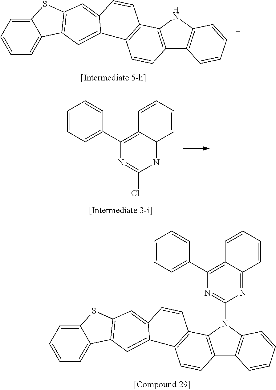


| TABLE 1 | ||||||
| Example | Host | V | Cd/m2 | CIEx | CIEy | T95 (Hr) |
| C. Ex. 1 | BAlq | 6.2 | 1510 | 0.665 | 0.334 | 45 |
| Ex. 1 | 1 | 5.0 | 1880 | 0.661 | 0.338 | 160 |
| Ex. 2 | 3 | 4.8 | 1760 | 0.663 | 0.336 | 150 |
| Ex. 3 | 6 | 4.7 | 1850 | 0.664 | 0.334 | 140 |
| Ex. 4 | 12 | 4.6 | 1690 | 0.665 | 0.335 | 130 |
| Ex. 5 | 29 | 4.7 | 1870 | 0.663 | 0.336 | 140 |
| Ex. 6 | 43 | 4.6 | 1900 | 0.663 | 0.336 | 140 |
| Ex. 7 | 44 | 4.8 | 1860 | 0.663 | 0.336 | 150 |
| Ex. 8 | 49 | 4.2 | 1910 | 0.660 | 0.338 | 160 |
| Ex. 9 | 65 | 4.8 | 1860 | 0.664 | 0.335 | 140 |
| Ex. 10 | 70 | 4.4 | 1880 | 0.662 | 0.337 | 130 |
| Ex. 11 | 74 | 4.8 | 1900 | 0.661 | 0.338 | 140 |
| Ex. 12 | 76 | 4.3 | 1860 | 0.663 | 0.336 | 150 |
| Ex. 13 | 77 | 4.2 | 1780 | 0.662 | 0.337 | 130 |
| Ex. 14 | 89 | 4.7 | 1970 | 0.660 | 0.338 | 150 |
| Ex. 15 | 104 | 4.7 | 1670 | 0.661 | 0.338 | 140 |
Claims (10)


Applications Claiming Priority (3)
| Application Number | Priority Date | Filing Date | Title |
|---|---|---|---|
| KR10-2015-0053728 | 2015-04-16 | ||
| KR1020150053728A KR102337550B1 (en) | 2015-04-16 | 2015-04-16 | Novel heterocyclic compounds and organic light-emitting diode including the same |
| PCT/KR2016/003485 WO2016167505A1 (en) | 2015-04-16 | 2016-04-05 | Novel heterocyclic compound and organic light emitting element including same |
Publications (2)
| Publication Number | Publication Date |
|---|---|
| US20180072753A1 US20180072753A1 (en) | 2018-03-15 |
| US10526342B2 true US10526342B2 (en) | 2020-01-07 |
Family
ID=57126146
Family Applications (1)
| Application Number | Title | Priority Date | Filing Date |
|---|---|---|---|
| US15/561,041 Active 2036-10-10 US10526342B2 (en) | 2015-04-16 | 2016-04-05 | Organic heterocyclic compound and light-emitting device comprising same |
Country Status (4)
| Country | Link |
|---|---|
| US (1) | US10526342B2 (en) |
| KR (2) | KR102337550B1 (en) |
| CN (1) | CN107428774B (en) |
| WO (1) | WO2016167505A1 (en) |
Families Citing this family (7)
| Publication number | Priority date | Publication date | Assignee | Title |
|---|---|---|---|---|
| GB201304526D0 (en) | 2013-03-13 | 2013-04-24 | Proximagen Ltd | New compounds |
| KR102292768B1 (en) * | 2015-10-13 | 2021-08-25 | 롬엔드하스전자재료코리아유한회사 | Organic Electroluminescent Compounds and Organic Electroluminescent Devices Comprising the Same |
| JPWO2018034242A1 (en) * | 2016-08-19 | 2019-06-20 | 出光興産株式会社 | Compound, material for organic electroluminescence device, organic electroluminescence device, and electronic device |
| CN111269232A (en) * | 2018-12-04 | 2020-06-12 | 北京鼎材科技有限公司 | Organic electroluminescent material and application thereof |
| US20230190728A1 (en) * | 2020-03-26 | 2023-06-22 | Proximagen, Llc | New therapeutic uses of compounds |
| CN112812119A (en) * | 2020-05-20 | 2021-05-18 | 陕西莱特光电材料股份有限公司 | Organic compound, and electronic element and device using same |
| CN113072560B (en) * | 2021-04-09 | 2023-11-24 | 北京八亿时空液晶科技股份有限公司 | Carbazole derivative and application thereof |
Citations (8)
| Publication number | Priority date | Publication date | Assignee | Title |
|---|---|---|---|---|
| KR20100074081A (en) | 2008-12-23 | 2010-07-01 | (주)루미나노 | Novel organic semiconductor compounds, preparation method of the same, and organic semiconductor compositions, organic semiconductor thin films and devices including the same |
| JP2010166070A (en) | 2010-03-04 | 2010-07-29 | Konica Minolta Holdings Inc | Organic electroluminescent element and display |
| KR20110013220A (en) | 2009-07-31 | 2011-02-09 | 다우어드밴스드디스플레이머티리얼 유한회사 | Novel organic electroluminescent compounds and organic electroluminescent device using the same |
| KR20120081539A (en) | 2011-01-11 | 2012-07-19 | (주)씨에스엘쏠라 | Organic light compound and organic light device using the same |
| CN102603748A (en) * | 2011-12-22 | 2012-07-25 | 山东大学 | Carbazole-based high-condensed ring dinitrogen-aza[7]helicene compound and synthetic method thereof |
| CN103570735A (en) | 2012-07-26 | 2014-02-12 | 三星显示有限公司 | Novel heterocyclic compounds and organic light emitting device comprising the same |
| US20140117326A1 (en) * | 2012-10-30 | 2014-05-01 | Sun-young Lee | Heterocyclic compound and organic light-emitting device including the same |
| KR20140057439A (en) | 2012-11-01 | 2014-05-13 | 삼성디스플레이 주식회사 | Heterocyclic compound and organic light emitting diode comprising the same |
Family Cites Families (2)
| Publication number | Priority date | Publication date | Assignee | Title |
|---|---|---|---|---|
| KR102081280B1 (en) * | 2013-01-30 | 2020-05-28 | 삼성디스플레이 주식회사 | Organic light emitting diode comprising the same |
| KR102137472B1 (en) * | 2013-02-08 | 2020-07-27 | 삼성디스플레이 주식회사 | Organic light emitting diode comprising the same |
-
2015
- 2015-04-16 KR KR1020150053728A patent/KR102337550B1/en active IP Right Grant
-
2016
- 2016-04-05 US US15/561,041 patent/US10526342B2/en active Active
- 2016-04-05 CN CN201680019052.0A patent/CN107428774B/en active Active
- 2016-04-05 WO PCT/KR2016/003485 patent/WO2016167505A1/en active Application Filing
-
2021
- 2021-10-07 KR KR1020210133108A patent/KR102393174B1/en active IP Right Grant
Patent Citations (13)
| Publication number | Priority date | Publication date | Assignee | Title |
|---|---|---|---|---|
| KR20100074081A (en) | 2008-12-23 | 2010-07-01 | (주)루미나노 | Novel organic semiconductor compounds, preparation method of the same, and organic semiconductor compositions, organic semiconductor thin films and devices including the same |
| CN102264698A (en) | 2008-12-23 | 2011-11-30 | 株式会社Luminano | Novel organic semiconductor compound, method for preparing same, and organic semiconductor composition, and organic semiconductor thin film and element containing same |
| KR20110013220A (en) | 2009-07-31 | 2011-02-09 | 다우어드밴스드디스플레이머티리얼 유한회사 | Novel organic electroluminescent compounds and organic electroluminescent device using the same |
| JP2010166070A (en) | 2010-03-04 | 2010-07-29 | Konica Minolta Holdings Inc | Organic electroluminescent element and display |
| KR20120081539A (en) | 2011-01-11 | 2012-07-19 | (주)씨에스엘쏠라 | Organic light compound and organic light device using the same |
| CN102603748A (en) * | 2011-12-22 | 2012-07-25 | 山东大学 | Carbazole-based high-condensed ring dinitrogen-aza[7]helicene compound and synthetic method thereof |
| CN103570735A (en) | 2012-07-26 | 2014-02-12 | 三星显示有限公司 | Novel heterocyclic compounds and organic light emitting device comprising the same |
| KR20140019082A (en) | 2012-07-26 | 2014-02-14 | 삼성디스플레이 주식회사 | Novel heterocycle compound and organic light emitting device comprising the same |
| US9118021B2 (en) * | 2012-07-26 | 2015-08-25 | Samsung Display Co., Ltd. | Heterocyclic compound and organic light-emitting device including the same |
| US20140117326A1 (en) * | 2012-10-30 | 2014-05-01 | Sun-young Lee | Heterocyclic compound and organic light-emitting device including the same |
| KR20140055137A (en) | 2012-10-30 | 2014-05-09 | 삼성디스플레이 주식회사 | Heterocyclic compound and organic light emitting device comprising the same |
| KR20140057439A (en) | 2012-11-01 | 2014-05-13 | 삼성디스플레이 주식회사 | Heterocyclic compound and organic light emitting diode comprising the same |
| CN103804333A (en) | 2012-11-01 | 2014-05-21 | 三星显示有限公司 | Heterocyclic compound and organic light emitting diode comprising the same |
Non-Patent Citations (4)
| Title |
|---|
| International Search Report of PCT/KR2016/003485, dated Apr. 5, 2016, English Translation. |
| Office Action from China National Intellectual Property Administration of 201680019052.0, dated Jul. 24, 2019. |
| Office action from China National Intellectual Property Administration of 2016800190520, dated Dec. 19, 2018. |
| SciFinder Search (May 24, 2019). * |
Also Published As
| Publication number | Publication date |
|---|---|
| KR20210127648A (en) | 2021-10-22 |
| KR102393174B1 (en) | 2022-05-02 |
| KR20160123561A (en) | 2016-10-26 |
| US20180072753A1 (en) | 2018-03-15 |
| KR102337550B1 (en) | 2021-12-13 |
| WO2016167505A1 (en) | 2016-10-20 |
| CN107428774A (en) | 2017-12-01 |
| CN107428774B (en) | 2021-01-01 |
Similar Documents
| Publication | Publication Date | Title |
|---|---|---|
| US20210184136A1 (en) | Organic light emitting diode for high efficiency | |
| US10947449B2 (en) | Organic light-emitting diode with high efficiency and long lifetime | |
| US11672172B2 (en) | Heterocyclic compound comprising aromatic amine group and organic light-emitting diode including the same | |
| US11133472B1 (en) | Organic light-emitting diode having long lifespan, low voltage, and high efficiency property | |
| US10741768B2 (en) | Organic light-emitting diode with high efficiency | |
| US10468603B2 (en) | Organic light-emitting diode having low driving voltage and long lifespan | |
| US10790450B2 (en) | Organic light-emitting diode with high efficiency and long lifetime | |
| US10526342B2 (en) | Organic heterocyclic compound and light-emitting device comprising same | |
| US11075343B2 (en) | Organic light emitting compounds and organic light emitting devices including the same | |
| US11683980B2 (en) | Condensed fluorene derivative comprising heterocyclic ring | |
| US10797259B2 (en) | Organic light-emitting diode with high efficiency | |
| US10950802B2 (en) | Organic light-emitting diode with high efficiency | |
| US20180093962A1 (en) | Novel organic compound and oranic light-emitting diode comprising same background of the invention | |
| US10014479B2 (en) | Organic light-emitting diode with high efficiency and long lifetime | |
| US20180351112A1 (en) | Novel organic light emitting compound and organic light emitting diode comprising same | |
| US20210288266A1 (en) | Organic light-emitting diode having long lifespan, low voltage, and high efficiency property | |
| US10559758B2 (en) | Organic light emitting diode of high efficiency | |
| US10529461B2 (en) | Heterocyclic compounds and organic light-emitting diode including the same | |
| US20170222160A1 (en) | Organic light emitting compounds and organic light emitting devices including the same | |
| US11251378B2 (en) | Organic light-emitting diode having alleviated luminance reduction in low dynamic range | |
| US10957865B2 (en) | Organic light emitting compound and organic light emitting diode including the same | |
| US11404647B2 (en) | Organic compound for organic light emitting diode and organic light emitting diode including same | |
| US20210257552A1 (en) | Organic light-emitting device | |
| US20190067588A1 (en) | Novel amine compound and organic light-emitting diode including same | |
| US9991449B2 (en) | Anthracene derivatives for organic light-emitting diode and organic light-emitting diode including the same |
Legal Events
| Date | Code | Title | Description |
|---|---|---|---|
| AS | Assignment |
Owner name: SFC CO., LTD., KOREA, REPUBLIC OF Free format text: ASSIGNMENT OF ASSIGNORS INTEREST;ASSIGNORS:YU, TAEJUNG;CHOI, YEONG-TAE;LEE, BONG-HYANG;AND OTHERS;REEL/FRAME:043675/0433 Effective date: 20170906 |
|
| FEPP | Fee payment procedure |
Free format text: ENTITY STATUS SET TO UNDISCOUNTED (ORIGINAL EVENT CODE: BIG.); ENTITY STATUS OF PATENT OWNER: SMALL ENTITY |
|
| FEPP | Fee payment procedure |
Free format text: ENTITY STATUS SET TO SMALL (ORIGINAL EVENT CODE: SMAL); ENTITY STATUS OF PATENT OWNER: SMALL ENTITY |
|
| STPP | Information on status: patent application and granting procedure in general |
Free format text: DOCKETED NEW CASE - READY FOR EXAMINATION |
|
| STPP | Information on status: patent application and granting procedure in general |
Free format text: NON FINAL ACTION MAILED |
|
| STPP | Information on status: patent application and granting procedure in general |
Free format text: RESPONSE TO NON-FINAL OFFICE ACTION ENTERED AND FORWARDED TO EXAMINER |
|
| STPP | Information on status: patent application and granting procedure in general |
Free format text: NOTICE OF ALLOWANCE MAILED -- APPLICATION RECEIVED IN OFFICE OF PUBLICATIONS |
|
| STPP | Information on status: patent application and granting procedure in general |
Free format text: PUBLICATIONS -- ISSUE FEE PAYMENT RECEIVED |
|
| STPP | Information on status: patent application and granting procedure in general |
Free format text: PUBLICATIONS -- ISSUE FEE PAYMENT VERIFIED |
|
| STCF | Information on status: patent grant |
Free format text: PATENTED CASE |
|
| MAFP | Maintenance fee payment |
Free format text: PAYMENT OF MAINTENANCE FEE, 4TH YR, SMALL ENTITY (ORIGINAL EVENT CODE: M2551); ENTITY STATUS OF PATENT OWNER: SMALL ENTITY Year of fee payment: 4 |