US1052487A - Clothes-line reel. - Google Patents
Clothes-line reel. Download PDFInfo
- Publication number
- US1052487A US1052487A US68877612A US1912688776A US1052487A US 1052487 A US1052487 A US 1052487A US 68877612 A US68877612 A US 68877612A US 1912688776 A US1912688776 A US 1912688776A US 1052487 A US1052487 A US 1052487A
- Authority
- US
- United States
- Prior art keywords
- line
- casing
- clothes
- drum
- reel
- Prior art date
- Legal status (The legal status is an assumption and is not a legal conclusion. Google has not performed a legal analysis and makes no representation as to the accuracy of the status listed.)
- Expired - Lifetime
Links
- 238000010276 construction Methods 0.000 description 4
- 238000004519 manufacturing process Methods 0.000 description 1
- 239000002023 wood Substances 0.000 description 1
Images

Classifications
-
- B—PERFORMING OPERATIONS; TRANSPORTING
- B60—VEHICLES IN GENERAL
- B60R—VEHICLES, VEHICLE FITTINGS, OR VEHICLE PARTS, NOT OTHERWISE PROVIDED FOR
- B60R22/00—Safety belts or body harnesses in vehicles
- B60R22/34—Belt retractors, e.g. reels
Definitions
- This invention relates to new and useful improvements in clothes line reels and has for its primary object to provide a construction which can be readily attached to the side of a house, post or other stationary object and which will be adapted to readily draw in the clothes line and receive the same when not in use, also permitting the line to be positioned at varying angles, as the occasion may require, for supporting the clothes.
- Another object of the invention is the provision of a clothes line reel upon which the line will be adapted to wind and unwind from the reel or drum confined within a receiver and which is controlled by means of a helical spring so that when the line is withdrawn or unwound from the reel the spring is placed under tension, the tension of the spring tending to rotate the drum and rewind the line when the same is released, the receiver being pivotally mounted for swinging movement thereby permitting the line to be disposed at varying angles.
- a still further object of the invention is to provide a clothes line reel of the above character which will possess advantages of efiiciency and durability, is inexpensive of manufacture and at the same time is simple in construction and operation.
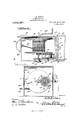
- Figure 1 is a perspective view showing the exterior of the casing or receiver.
- Fig. 2 is a plan view, the lid or cover being thrown back to disclose the interior of the casing.
- Fig. 3 is a sectional view on the line 3-3 of Fig. 2, and
- Fig. 4 is a detail perspective view of the U-shaped bracket.
- 1 indicates the receiver or casing which is preferably constructed from wood and may be made in two sections 2 and 3, the section 3 comprising a suitable lid or quires.
- the cover which is hinged to the upper edge of the body section 2 by means of the hinges 4.
- a U shaped bracket 5 having its intermediate portion looped to form an eye 6 which is disposed through the opening 7 in the rear of the casing and adapted to be engaged over the hook member 8 secured to any suitable stationary object.
- the receiver or casing may be swung to varying angles as the occasion re- Transversely arranged within the body section is the horizontally disposed shaft 9 upon which is mounted a suitable reel or drum 10.
- a pinion 11 adapted to mesh with the gear 12 which is suitably mounted upon the inwardly extending shaft 13, said shaft having one of its ends securely mounted in the side wall of the body section and held in position by the nut 14 threaded upon the end thereof.
- the sleeve 15 Formed integral with one side of the gear wheel is the sleeve 15 adapted to be loosely mounted upon the shaft 13.
- the helical spring 16 Mounted upon the sleeve and having one end secured thereto is the helical spring 16, the outer end of said sprin being secured to the inwardly extending olt 17 which is secured at one of its ends to the casing 2 by means of a nut 18 threaded thereon.
- a ratchet 19 is mounted upon one end of the shaft 9 and arranged upon the outer' side of the casing, said ratchet being held securely in place by means of a nut 20 threaded upon the outer end of the shaft.
- a suitable pawl 21 is pivotally secured to the body section and adapted to engage the ratchet 19 to prevent backward movement of the drum 10.
- Mounted upon the other end of the shaft 9 is a crank handle 22 which is adapted to rotate the drum 10, when the line has been Withdrawn to the required distance to tighten the same, the pawl 21 holding the drum 10 against movement so that the line will be held taut.
- the hand-hold 24 is provided at its ends with the beveled faces 25 adapted to engage with the beveled faces 26 formed upon the side edges of the opening 23 to prevent the handhold 24 from passing entirely into the easing, the same being held in position by the tension of the sprlng 16 so that it may be pasily and quickly grasped to withdraw the
- the line is unwound from the drum by grasping the hand-hold 24 and fastening the line to a suitable support which may be located at any required distance from the receiver, the unwinding of the line from the drum 1O placing the spring 16 under tension so that when the line is released the tension of the spring will rotate the drum and rewind the line.
- the reel which is suitably housed within a casing or receiver to protect the clothesline and the reel from rain, sleet, or snow, the receiver being pivotally mounted for swinging movement to permit the line to be disposed at varying angles.
- a clothes line reel In a clothes line reel, the combination of a sectional casing having an opening formed in one end thereof, a U-shaped bracket arranged within the casing, said bracket having its intermediate portion looped to form an eye which is disposed through the opening and arranged upon the outer side of the casing, a rotatable drum mounted within the casing, a helical spring arranged within the casing and adapted to rotate said drum when the same is placed under tension, a line arranged upon said drum, the front wall of said casing formed with an opening,
Landscapes
- Engineering & Computer Science (AREA)
- Mechanical Engineering (AREA)
- Storing, Repeated Paying-Out, And Re-Storing Of Elongated Articles (AREA)
Description
J. H. KRIDER.
CLOTHES LINE REEL.
APPLIGATION FILED APR.5, 1912.
1,052,487, Patented Feb. 11, 1913.
2 SHBETSSHEET 1.
Eva-.1
a W. Q fibtozwug COLUMBIA PLANOGRAPH cm. WASHINGTON. D. c.
J. H. KRIDER.
.GLOTHES LINE REEL.
APPLICATION FILED APR.5, 1912. 1,052,487.. Patented Feb. 11, 1913.
2 SHEETS-SHEET 2.
Erna- Snow V606 wi/tmeooeo a?) W 11 I Cutout COLUMBIA PLANOGRAPH 6a., WASHINGTON, D. c.
JESSE H. KRIDER, OF BUTLER, PENNSYLVANIA.
CLOTHES-LINE REEL.
Specification of Letters Patent.
Patented Feb. 11,1913.
Application filed April 5, 1912. Serial No. 688,776.
To all whom it may concern:
Be it known that 1, Jesse H. KRIDER, a citizen of the United States, residing at Butler, in the county of Butler and State of Pennsylvania, have invented certain new and useful Improvements in Clothes-Line Reels, of which the following is a specification, reference being had to the accompanying drawings.
This invention relates to new and useful improvements in clothes line reels and has for its primary object to provide a construction which can be readily attached to the side of a house, post or other stationary object and which will be adapted to readily draw in the clothes line and receive the same when not in use, also permitting the line to be positioned at varying angles, as the occasion may require, for supporting the clothes.
Another object of the invention is the provision of a clothes line reel upon which the line will be adapted to wind and unwind from the reel or drum confined within a receiver and which is controlled by means of a helical spring so that when the line is withdrawn or unwound from the reel the spring is placed under tension, the tension of the spring tending to rotate the drum and rewind the line when the same is released, the receiver being pivotally mounted for swinging movement thereby permitting the line to be disposed at varying angles.
A still further object of the invention is to provide a clothes line reel of the above character which will possess advantages of efiiciency and durability, is inexpensive of manufacture and at the same time is simple in construction and operation.
lVith the above and other objects in view the invention consists in the novel features of construction, combination and arrangement of parts hereinafter more fully clescribed, pointed out in the claim and shown in the accompanying drawings, in which,
Figure 1 is a perspective view showing the exterior of the casing or receiver. Fig. 2 is a plan view, the lid or cover being thrown back to disclose the interior of the casing. Fig. 3 is a sectional view on the line 3-3 of Fig. 2, and Fig. 4 is a detail perspective view of the U-shaped bracket.
Referring more particularly to the drawings, 1 indicates the receiver or casing which is preferably constructed from wood and may be made in two sections 2 and 3, the section 3 comprising a suitable lid or quires.
cover which is hinged to the upper edge of the body section 2 by means of the hinges 4. Horizontally disposed within the body section 2 is a U shaped bracket 5 having its intermediate portion looped to form an eye 6 which is disposed through the opening 7 in the rear of the casing and adapted to be engaged over the hook member 8 secured to any suitable stationary object. Thus it will be seen that the receiver or casing may be swung to varying angles as the occasion re- Transversely arranged Within the body section is the horizontally disposed shaft 9 upon which is mounted a suitable reel or drum 10. Mounted upon the shaft 9 and arranged adjacent one end of the drum is a pinion 11 adapted to mesh with the gear 12 which is suitably mounted upon the inwardly extending shaft 13, said shaft having one of its ends securely mounted in the side wall of the body section and held in position by the nut 14 threaded upon the end thereof.
Formed integral with one side of the gear wheel is the sleeve 15 adapted to be loosely mounted upon the shaft 13. Mounted upon the sleeve and having one end secured thereto is the helical spring 16, the outer end of said sprin being secured to the inwardly extending olt 17 which is secured at one of its ends to the casing 2 by means of a nut 18 threaded thereon. Thus it will be seen that as the line is withdrawn or unwound from the reel 10, the pinion 11 will rotate the gear 12 and place the spring 16 under tension, the tension of the spring tending to rotate the drum and rewind the line when the same is released. To prevent any backward movement of the drum 10 when the line is being unwound therefrom, a ratchet 19 is mounted upon one end of the shaft 9 and arranged upon the outer' side of the casing, said ratchet being held securely in place by means of a nut 20 threaded upon the outer end of the shaft. A suitable pawl 21 is pivotally secured to the body section and adapted to engage the ratchet 19 to prevent backward movement of the drum 10. Mounted upon the other end of the shaft 9 is a crank handle 22 which is adapted to rotate the drum 10, when the line has been Withdrawn to the required distance to tighten the same, the pawl 21 holding the drum 10 against movement so that the line will be held taut.
In unwinding the line 22 from the drum 10 the same is to be withdrawn from the casing through the opening 23 formed in one end of the body section 2. A suitable hand-hold 24 is secured to the outer end of the line sothat the same can be quickly and easily withdrawn from the casing. The hand-hold 24 is provided at its ends with the beveled faces 25 adapted to engage with the beveled faces 26 formed upon the side edges of the opening 23 to prevent the handhold 24 from passing entirely into the easing, the same being held in position by the tension of the sprlng 16 so that it may be pasily and quickly grasped to withdraw the When it is desired to suspend the line for supporting clothes, the line is unwound from the drum by grasping the hand-hold 24 and fastening the line to a suitable support which may be located at any required distance from the receiver, the unwinding of the line from the drum 1O placing the spring 16 under tension so that when the line is released the tension of the spring will rotate the drum and rewind the line.
From the above description taken in connection with the drawings, it will be seen that I have provided a novel clothes line,
reel which is suitably housed within a casing or receiver to protect the clothesline and the reel from rain, sleet, or snow, the receiver being pivotally mounted for swinging movement to permit the line to be disposed at varying angles.
WVhile I have shown and described the preferred form of my invention it will be obvious that various changes in the details of construction and in the proportions may be resorted to for successfully carrying the invention into practice without sacrificing any of the novel features or departing from the scope thereof.
Having thus described the invention what is claimed is:
In a clothes line reel, the combination of a sectional casing having an opening formed in one end thereof, a U-shaped bracket arranged within the casing, said bracket having its intermediate portion looped to form an eye which is disposed through the opening and arranged upon the outer side of the casing, a rotatable drum mounted within the casing, a helical spring arranged within the casing and adapted to rotate said drum when the same is placed under tension, a line arranged upon said drum, the front wall of said casing formed with an opening,
a closure for said opening, the outer end of said line being secured to the inner wall of said closure, a hand hold formed on the outer wall of said closure, said closure adapted to be removed from the opening in the casing and secured to a suitable support at any desired distance from said casing, the said closure adapted to be held in a closed position by an action of said spring, the edges of the said opening and said closure being beveled thereby preventing the closure from passing entirely within the casing, as and for the purpose hereinbefore set forth.
In testimony whereof I hereunto afliX my signature in the presence of two witnesses.
JESSE H. KRIDER.
Witnesses:
S. F. BOWSER, J. H. FITHIAN.
Copies of this patent may be obtained for five cents each, by addressing the Commissioner of Patents, Washington, D. C.
Priority Applications (1)
| Application Number | Priority Date | Filing Date | Title |
|---|---|---|---|
| US68877612A US1052487A (en) | 1912-04-05 | 1912-04-05 | Clothes-line reel. |
Applications Claiming Priority (1)
| Application Number | Priority Date | Filing Date | Title |
|---|---|---|---|
| US68877612A US1052487A (en) | 1912-04-05 | 1912-04-05 | Clothes-line reel. |
Publications (1)
| Publication Number | Publication Date |
|---|---|
| US1052487A true US1052487A (en) | 1913-02-11 |
Family
ID=3120748
Family Applications (1)
| Application Number | Title | Priority Date | Filing Date |
|---|---|---|---|
| US68877612A Expired - Lifetime US1052487A (en) | 1912-04-05 | 1912-04-05 | Clothes-line reel. |
Country Status (1)
| Country | Link |
|---|---|
| US (1) | US1052487A (en) |
Cited By (1)
| Publication number | Priority date | Publication date | Assignee | Title |
|---|---|---|---|---|
| US20100072314A1 (en) * | 2008-09-19 | 2010-03-25 | Alan Sherman | Wall-mounted retractable clothesline assembly |
-
1912
- 1912-04-05 US US68877612A patent/US1052487A/en not_active Expired - Lifetime
Cited By (1)
| Publication number | Priority date | Publication date | Assignee | Title |
|---|---|---|---|---|
| US20100072314A1 (en) * | 2008-09-19 | 2010-03-25 | Alan Sherman | Wall-mounted retractable clothesline assembly |
Similar Documents
| Publication | Publication Date | Title |
|---|---|---|
| US703709A (en) | Adjustable hanger. | |
| US1014266A (en) | Door-closer. | |
| US1016493A (en) | Clothes-line reel. | |
| US969598A (en) | Clothes-line reel. | |
| US1061642A (en) | Clothes-line reel. | |
| US2872047A (en) | Retractable clothesline device | |
| US1493436A (en) | Automatic clothesline rack | |
| US1214772A (en) | Wire carrier and stretcher. | |
| US1272270A (en) | Automatic chalk-line holder. | |
| US1292361A (en) | Winding-reel. | |
| US1153188A (en) | Hitching device. | |
| US1512188A (en) | Reel | |
| US690588A (en) | Clothes-line reel. | |
| US542564A (en) | Line-reel | |
| US393063A (en) | Time mechanism for dampers | |
| US1018550A (en) | Fish-line drier. | |
| US1004753A (en) | Clothes-line reel. | |
| US1017010A (en) | Clothes-line reel. | |
| US1133511A (en) | Razor-strop holder. | |
| US1015413A (en) | Window-screen. | |
| US1053658A (en) | Shade-roll-operating device. | |
| US565064A (en) | Clothes-line reel | |
| US684742A (en) | Door-spring. | |
| US938388A (en) | Clothes-line reel and stretcher. | |
| US807591A (en) | Fence-gate. |