US10524829B2 - Trocar support - Google Patents
Trocar support Download PDFInfo
- Publication number
- US10524829B2 US10524829B2 US15/354,624 US201615354624A US10524829B2 US 10524829 B2 US10524829 B2 US 10524829B2 US 201615354624 A US201615354624 A US 201615354624A US 10524829 B2 US10524829 B2 US 10524829B2
- Authority
- US
- United States
- Prior art keywords
- annular
- tubular device
- fluid
- trocar
- collar
- Prior art date
- Legal status (The legal status is an assumption and is not a legal conclusion. Google has not performed a legal analysis and makes no representation as to the accuracy of the status listed.)
- Active, expires
Links
- 239000012530 fluid Substances 0.000 claims abstract description 92
- 210000003811 finger Anatomy 0.000 claims description 26
- 230000000694 effects Effects 0.000 claims description 9
- 210000003813 thumb Anatomy 0.000 claims description 9
- 230000009471 action Effects 0.000 description 13
- 230000006835 compression Effects 0.000 description 12
- 238000007906 compression Methods 0.000 description 12
- 238000003780 insertion Methods 0.000 description 11
- 230000037431 insertion Effects 0.000 description 11
- 230000008878 coupling Effects 0.000 description 9
- 238000010168 coupling process Methods 0.000 description 9
- 238000005859 coupling reaction Methods 0.000 description 9
- 230000001954 sterilising effect Effects 0.000 description 9
- 238000010276 construction Methods 0.000 description 7
- 230000002093 peripheral effect Effects 0.000 description 7
- 230000007246 mechanism Effects 0.000 description 6
- 230000000994 depressogenic effect Effects 0.000 description 5
- 238000000034 method Methods 0.000 description 5
- 210000003195 fascia Anatomy 0.000 description 4
- IAYPIBMASNFSPL-UHFFFAOYSA-N Ethylene oxide Chemical compound C1CO1 IAYPIBMASNFSPL-UHFFFAOYSA-N 0.000 description 2
- 230000008901 benefit Effects 0.000 description 2
- 239000000463 material Substances 0.000 description 2
- 230000008569 process Effects 0.000 description 2
- 238000005086 pumping Methods 0.000 description 2
- 238000007789 sealing Methods 0.000 description 2
- 238000004659 sterilization and disinfection Methods 0.000 description 2
- 238000013459 approach Methods 0.000 description 1
- 238000004140 cleaning Methods 0.000 description 1
- 208000014674 injury Diseases 0.000 description 1
- 238000010297 mechanical methods and process Methods 0.000 description 1
- 239000002184 metal Substances 0.000 description 1
- 230000005012 migration Effects 0.000 description 1
- 238000013508 migration Methods 0.000 description 1
- 238000000926 separation method Methods 0.000 description 1
- 229920002379 silicone rubber Polymers 0.000 description 1
- 239000004945 silicone rubber Substances 0.000 description 1
- 238000001356 surgical procedure Methods 0.000 description 1
- 230000008733 trauma Effects 0.000 description 1
Images


Classifications
-
- A—HUMAN NECESSITIES
- A61—MEDICAL OR VETERINARY SCIENCE; HYGIENE
- A61B—DIAGNOSIS; SURGERY; IDENTIFICATION
- A61B17/00—Surgical instruments, devices or methods, e.g. tourniquets
- A61B17/34—Trocars; Puncturing needles
-
- A—HUMAN NECESSITIES
- A61—MEDICAL OR VETERINARY SCIENCE; HYGIENE
- A61B—DIAGNOSIS; SURGERY; IDENTIFICATION
- A61B17/00—Surgical instruments, devices or methods, e.g. tourniquets
- A61B17/34—Trocars; Puncturing needles
- A61B17/3417—Details of tips or shafts, e.g. grooves, expandable, bendable; Multiple coaxial sliding cannulas, e.g. for dilating
-
- A—HUMAN NECESSITIES
- A61—MEDICAL OR VETERINARY SCIENCE; HYGIENE
- A61B—DIAGNOSIS; SURGERY; IDENTIFICATION
- A61B17/00—Surgical instruments, devices or methods, e.g. tourniquets
- A61B17/02—Surgical instruments, devices or methods, e.g. tourniquets for holding wounds open; Tractors
- A61B17/0218—Surgical instruments, devices or methods, e.g. tourniquets for holding wounds open; Tractors for minimally invasive surgery
-
- A—HUMAN NECESSITIES
- A61—MEDICAL OR VETERINARY SCIENCE; HYGIENE
- A61B—DIAGNOSIS; SURGERY; IDENTIFICATION
- A61B17/00—Surgical instruments, devices or methods, e.g. tourniquets
- A61B17/34—Trocars; Puncturing needles
- A61B17/3403—Needle locating or guiding means
-
- A—HUMAN NECESSITIES
- A61—MEDICAL OR VETERINARY SCIENCE; HYGIENE
- A61B—DIAGNOSIS; SURGERY; IDENTIFICATION
- A61B17/00—Surgical instruments, devices or methods, e.g. tourniquets
- A61B17/34—Trocars; Puncturing needles
- A61B17/3417—Details of tips or shafts, e.g. grooves, expandable, bendable; Multiple coaxial sliding cannulas, e.g. for dilating
- A61B17/3421—Cannulas
- A61B17/3423—Access ports, e.g. toroid shape introducers for instruments or hands
-
- A—HUMAN NECESSITIES
- A61—MEDICAL OR VETERINARY SCIENCE; HYGIENE
- A61B—DIAGNOSIS; SURGERY; IDENTIFICATION
- A61B17/00—Surgical instruments, devices or methods, e.g. tourniquets
- A61B2017/00477—Coupling
-
- A—HUMAN NECESSITIES
- A61—MEDICAL OR VETERINARY SCIENCE; HYGIENE
- A61B—DIAGNOSIS; SURGERY; IDENTIFICATION
- A61B17/00—Surgical instruments, devices or methods, e.g. tourniquets
- A61B2017/00535—Surgical instruments, devices or methods, e.g. tourniquets pneumatically or hydraulically operated
- A61B2017/00557—Surgical instruments, devices or methods, e.g. tourniquets pneumatically or hydraulically operated inflatable
-
- A—HUMAN NECESSITIES
- A61—MEDICAL OR VETERINARY SCIENCE; HYGIENE
- A61B—DIAGNOSIS; SURGERY; IDENTIFICATION
- A61B17/00—Surgical instruments, devices or methods, e.g. tourniquets
- A61B2017/00831—Material properties
- A61B2017/00862—Material properties elastic or resilient
-
- A—HUMAN NECESSITIES
- A61—MEDICAL OR VETERINARY SCIENCE; HYGIENE
- A61B—DIAGNOSIS; SURGERY; IDENTIFICATION
- A61B17/00—Surgical instruments, devices or methods, e.g. tourniquets
- A61B17/02—Surgical instruments, devices or methods, e.g. tourniquets for holding wounds open; Tractors
- A61B17/0218—Surgical instruments, devices or methods, e.g. tourniquets for holding wounds open; Tractors for minimally invasive surgery
- A61B2017/0225—Surgical instruments, devices or methods, e.g. tourniquets for holding wounds open; Tractors for minimally invasive surgery flexible, e.g. fabrics, meshes, or membranes
-
- A—HUMAN NECESSITIES
- A61—MEDICAL OR VETERINARY SCIENCE; HYGIENE
- A61B—DIAGNOSIS; SURGERY; IDENTIFICATION
- A61B17/00—Surgical instruments, devices or methods, e.g. tourniquets
- A61B17/34—Trocars; Puncturing needles
- A61B17/3403—Needle locating or guiding means
- A61B2017/3405—Needle locating or guiding means using mechanical guide means
- A61B2017/3407—Needle locating or guiding means using mechanical guide means including a base for support on the body
-
- A—HUMAN NECESSITIES
- A61—MEDICAL OR VETERINARY SCIENCE; HYGIENE
- A61B—DIAGNOSIS; SURGERY; IDENTIFICATION
- A61B17/00—Surgical instruments, devices or methods, e.g. tourniquets
- A61B17/34—Trocars; Puncturing needles
- A61B2017/348—Means for supporting the trocar against the body or retaining the trocar inside the body
- A61B2017/3482—Means for supporting the trocar against the body or retaining the trocar inside the body inside
- A61B2017/3484—Anchoring means, e.g. spreading-out umbrella-like structure
- A61B2017/3486—Balloon
-
- A—HUMAN NECESSITIES
- A61—MEDICAL OR VETERINARY SCIENCE; HYGIENE
- A61B—DIAGNOSIS; SURGERY; IDENTIFICATION
- A61B17/00—Surgical instruments, devices or methods, e.g. tourniquets
- A61B17/34—Trocars; Puncturing needles
- A61B2017/348—Means for supporting the trocar against the body or retaining the trocar inside the body
- A61B2017/3492—Means for supporting the trocar against the body or retaining the trocar inside the body against the outside of the body
Definitions
- a trocar is a tubular device which extends through a body wall of a patient to enable internal surgical procedures so that reference herein to a trocar is intended to include any such tubular device of this type.
- a support apparatus for supporting a trocar while the trocar extends through a body wall of a patient includes an inflatable collar extending around the trocar which can be inflated to a predetermined size by a source of fluid where the source of fluid is located on the trocar support apparatus itself so as to be carried thereby and is defined by a pump mechanism to provide a fixed volume allowing inflation only to a fixed size.
- An abutment member is shaped to be received on an outer surface of the trocar sleeve and adjustable longitudinally of the trocar sleeve so as to be located at a selected position.
- a tube connecting the pump on the abutment to the inflatable collar is wrapped helically around the sleeve of the trocar.
- a trocar support apparatus for use with a trocar separate from the apparatus for maintaining the trocar in fixed position in a body wall of a patient while the trocar extends through the body wall of a patient, the support comprising:
- annular expandable member for extending around the trocar, said annular expandable member being movable in an expansion movement from a collapsed condition radially outwardly of the trocar to a predetermined size
- annular abutment collar arranged to be received on the trocar at a required position thereon;
- annular abutment collar being adjustable longitudinally of the trocar so as to be located at a selected position
- annular expandable member being arranged while in said collapsed condition to be inserted through an incision in the body wall and expanded when inserted to engage an inside surface of the body wall;
- annular expandable member is expandable by a manually operable device providing a source of the fluid mounted on the annular abutment collar;
- the manually operable device comprises a pair of annular members locating a fluid containing member therebetween, the annular members and the fluid containing member surrounding a central opening for passage therethrough of the trocar;
- a trocar support apparatus for use with a trocar separate from the apparatus for maintaining the trocar in fixed position in a body wall of a patient while the trocar extends through the body wall of a patient, the support comprising:
- annular expandable member for extending around the trocar, said annular expandable member being movable in an expansion movement from a collapsed condition radially outwardly of the trocar to a predetermined size
- annular abutment collar arranged to be received on the trocar at a required position thereon;
- annular abutment collar being adjustable longitudinally of the trocar so as to be located at a selected position
- annular expandable member being arranged while in said collapsed condition to be inserted through an incision in the body wall and expanded when inserted to engage an inside surface of the body wall;
- annular expandable member comprises an elastomeric sleeve portion having an inner surface arranged to engage onto the trocar;
- a trocar support apparatus for use with a trocar separate from the apparatus for maintaining the trocar in fixed position in a body wall of a patient while the trocar extends through the body wall of a patient, the support comprising:
- annular expandable member for extending around the trocar, said annular expandable member being movable in an expansion movement from a collapsed condition radially outwardly of the trocar to a predetermined size
- annular abutment collar arranged to be received on the trocar at a required position thereon;
- annular abutment collar being adjustable longitudinally of the trocar so as to be located at a selected position
- annular expandable member being arranged while in said collapsed condition to be inserted through an incision in the body wall and expanded when inserted to engage an inside surface of the body wall;
- a connecting component mounted on the annular abutment collar for engaging a portion of the annular expandable member to engage and hold the annular expandable member in engagement with the annular abutment collar for common insertion of the trocar therethrough to a required position of the annular expandable member on the trocar;
- a release member operable to release the connecting component to effect release of the annular expandable member from the annular abutment collar so that when released the annular abutment collar is movable longitudinally relative to the annular expandable member such that the annular abutment collar is moved to a position to hold the body wall between the annular abutment collar and the annular expandable member.
- a trocar support apparatus for use with a trocar separate from the apparatus for maintaining the trocar in fixed position in a body wall of a patient while the trocar extends through the body wall of a patient, the support comprising:
- annular expandable member for extending around the trocar, said annular expandable member being movable in an expansion movement from a collapsed condition radially outwardly of the trocar to a predetermined size
- annular abutment collar arranged to be received on the trocar at a required position thereon;
- annular abutment collar being adjustable longitudinally of the trocar so as to be located at a selected position
- annular expandable member being arranged while in said collapsed condition to be inserted through an incision in the body wall and expanded when inserted to engage an inside surface of the body wall;
- the manually operable device comprises a pair of members locating an inflation fluid containing member therebetween;
- fluid containing member can be opened to enable the entry of sterilizing fluid and closed to effect the expulsion of the inflation fluid.
- the fluid containing member is opened by a valve.
- the fluid containing member is movable to a position where a chamber defined therebetween is opened to allow the entry of the sterilization fluid and then is closed to enclose a volume of the inflation fluid.
- a trocar support apparatus for use with a trocar separate from the apparatus for maintaining the trocar in fixed position in a body wall of a patient while the trocar extends through the body wall of a patient, the support comprising:
- annular expandable member for extending around the trocar, said annular expandable member being movable in an expansion movement from a collapsed condition radially outwardly of the trocar to a predetermined size
- annular abutment collar arranged to be received on the trocar at a required position thereon;
- annular abutment collar being adjustable longitudinally of the trocar so as to be located at a selected position
- annular expandable member being arranged while in said collapsed condition to be inserted through an incision in the body wall and expanded when inserted to engage an inside surface of the body wall;
- the manually operable device comprises a pair of members locating an inflation fluid containing member therebetween;
- the members including a manually engageable projection extending generally radially outwardly from the annular abutment collar;
- a manually operable compression device for rotating one member around the axis of the trocar toward of the other member for expelling the inflation fluid from the fluid containing member.
- one of the annular members comprises a cylinder and the other of the annular members comprises a piston defining a chamber in the cylinder so that the movement in the axial direction causes the chamber to be reduced in volume expelling the fluid therefrom.
- the cylinder and the piston can be moved to a position allowing entry of a sterilizing fluid material from the exterior to enable the chamber to be properly sterilized.
- the manually operable compression device comprises a screw thread interconnecting the annular members so that rotation of one around the axis causes said relative axial movement.
- the screw thread is on an outside surface of one of the annular members.
- the manually operable compression device includes a latch for holding the annular members in fixed position after a volume of fluid is supplied.
- the annular members are moved by squeezing together two abutments projecting from an exterior of each of the annular members where at least one of the abutments is rotatable around the axis.
- a latch extending between the abutments for holding the abutments in fixed position after the fluid is supplied.
- a spring which rotates the annular members in a return direction to a retracted position to deflate the expandable member.
- the spring is located between the annular members and is wound around the trocar.
- a connecting component mounted on the annular abutment collar for engaging a portion of the annular expandable member to engage and hold the annular expandable member in engagement with the annular abutment collar for common insertion of the trocar therethrough to a required position of the annular expandable member on the trocar and a release member operable to release the connecting component to effect release of the annular expandable member from the annular abutment collar so that when released the annular abutment collar is movable longitudinally relative to the annular expandable member such that the annular abutment collar is moved to a position to hold the body wall between the annular abutment collar and the annular expandable member.
- the surface of the connecting component surrounds the trocar so that a portion of the annular expandable member projects axially into the interior of the surface.
- the connecting component comprises a ring on the annular expandable member which is held by a sliding plate on the annular abutment collar with an opening in the plate to hold and release the ring.
- the annular expandable member includes a sleeve slightly bigger than the trocar with an internal peripheral rib which engages over a rib on the trocar to lock the annular expandable member in place.
- the annular expandable member is inflatable by a fluid.
- other techniques for expansion of the expandable member can be used.
- the manually operable device is mounted on the annular abutment collar.
- Other mounting arrangements can however be used.
- the manually operable device comprises a pair of discs with a fluid containing member such as a balloon, located therebetween, the discs and the fluid containing member surrounding a central opening for passage therethrough of the trocar.
- a manually operable compression device such as a threaded member rotatable on the device for squeezing one of the discs toward of the other discs for compression of the fluid containing member.
- the coupling arrangement includes an insert sleeve portion engageable into a hollow interior of the elastomeric sleeve portion for engaging the inner surface and the holding the inner surface open for passage of the trocar.
- the insert sleeve portion is tapered so as to hold the elastomeric sleeve portion in a frustoconical portion at the end edge of the elastomeric sleeve portion. This allows the trocar to slide through sleeve portion and to be guided into the leading edge of the elastomeric sleeve to reduce longitudinal forces on the elastomeric sleeve which could otherwise cause it to move longitudinally with the trocar.
- the coupling arrangement includes a peripheral engagement member for clamping a portion of the elastomeric sleeve portion against the insert sleeve portion. This acts to hold the elastomeric sleeve clamped in position with the annular abutment collar until it is released to allow the collar to slide away from the elastomeric sleeve for the insertion process in the body cavity of the patient.
- the peripheral engagement member is releasable from the insert sleeve portion and the elastomeric sleeve portion by the manually operable release member.
- the release member is movable axially to release the peripheral engagement member, for example by rotation on a screw thread.
- annular expandable member or elastomeric member is clamped between an inner insert sleeve portion and an outer peripheral engagement member to hold the edge portion clamped to the annular abutment collar.
- the releasable clamping member on the annular abutment collar comprises a disk member having a central opening for surrounding the trocar, the central opening having an edge portion spring biased in a direction axially toward the trocar for engaging the trocar, and the disk member having a manually engageable portion exposed at one side of the annular abutment collar for pressing the disk member in a direction of the central opening axially away from the trocar against the spring bias.
- a tubular conduit which connects the source of fluid to the annular expandable member wrapped helically around the trocar.
- FIG. 1 is an isometric view from the top and one side of a trocar support according to the present invention.
- FIG. 2 is a first side elevational view of the embodiment of FIG. 1 .
- FIG. 3 is a second side elevational view of the embodiment of FIG. 1 .
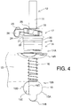
- FIG. 4 is a third side elevational view of the embodiment of FIG. 1 shown in an expanded position.
- FIG. 5 is a first longitudinal cross-sectional view of the embodiment of FIG. 1 showing the expandable member and the collar in a position latched together.
- FIG. 6 is a second longitudinal cross-sectional view of the embodiment of FIG. 1 .
- FIG. 7 is an exploded view of the embodiment of FIG. 1 .
- FIG. 8 is a cross-sectional view along the lines 9 - 9 of FIG. 6 .
- like characters of reference indicate corresponding parts in the different figures.
- FIG. 9 is a longitudinal cross-sectional view of a second embodiment of the trocar support according to the present invention.
- FIG. 10 is a longitudinal cross-sectional view of a third embodiment of the trocar support according to the present invention.
- FIG. 11 is a longitudinal cross-sectional view of the embodiment of FIG. 10 .
- FIG. 12 is an isometric view from the top and one side of a trocar support according to a fourth embodiment of the present invention in a first position of the inflation system.
- FIG. 12A is a view similar to that of FIG. 12 showing the inflation system in a final position of the inflation system.
- FIG. 13 is an isometric view partly in cross-sectional of the embodiment of FIG. 12 .
- FIG. 14 is an exploded view of the embodiment of FIG. 12 showing the internal components.
- FIG. 15 is an isometric view of one part only of the embodiment of FIG. 12 showing the arrangement for releasably clamping the slidable collar to the trocar.
- FIG. 16 is an isometric view of one part only of the embodiment of FIG. 12 showing the arrangement for releasably connecting the expandable collar to the slidable collar.
- FIG. 17 is an isometric view partly in cross-section similar to that of FIG. 13 showing the inflation system in the final position.
- FIG. 18 is a cross-sectional view along the lines 18 - 18 of the embodiment of FIG. 12 showing the inflation system in a partly inflated position.
- FIG. 19 is a cross-sectional view similar to that of FIG. 18 showing a further embodiment of the invention.
- FIG. 20 is a top plan view of the embodiment of FIG. 19 .
- FIG. 21 is a side elevational view of the embodiment of FIG. 19 .
- FIGS. 1 to 9 a trocar support 10 for attachment to a trocar 12 to support a sleeve 11 of the trocar 12 while the sleeve 11 penetrates through a body wall 13 of a patient as shown schematically in the FIG. 4 .
- the support 10 comprises an abutment member 14 shaped to be received on an outer surface of the trocar sleeve.
- the abutment member forms a collar 14 A surrounding the sleeve with a manually operable clamp 14 B for releasable connection to the sleeve 11 so as to be adjustable longitudinally of the trocar sleeve 11 so as to be located at a selected position 11 A as shown in FIG. 4 .
- the support 10 includes an inflatable collar 15 for mounting on the trocar sleeve 11 at a required position 15 B spaced from the abutment member 14 at the position 11 A.
- the inflatable collar can be inflated by a source of fluid, typically air or other gas, from a pump 17 to a predetermined size through a supply tube 16 .
- the inflatable collar while deflated can be inserted on the trocar sleeve through an incision in the body wall and can be inflated from the pump 17 through the tube 16 when inserted to the inflated condition shown in FIG. 4 at 15 A to engage an inside surface of the body wall 13 .
- the abutment member can be moved to a position 11 A to hold the body wall 13 between the abutment member 14 and the inflatable collar 15 .
- the source of fluid provided by the pump 17 is located on the trocar support and particularly the abutment member 14 so as to be carried thereby.
- the source of fluid therefore is a pump mechanism forming a part of the trocar support and operable by hand.
- the source of fluid 17 provides a fixed volume allowing inflation of the collar 15 only to a fixed size.
- the tube 16 is of a circular cross-section or in some cases of a flattened cross-section so as to lie flat against the sleeve of the trocar and is wrapped helically around the sleeve of the trocar. Thus it can lie in compressed side by side turns as shown in the initial position in FIG. 1 and can extend axially as shown in FIG. 4 .
- the inflatable collar 15 and the abutment member 14 form a common collar portion 10 which can be engaged onto the trocar sleeve 11 and moved axially therealong from the lower insertion end to a required position along the length of the trocar sleeve.
- a connection system 19 In order to hold the assembly rigid and intact for insertion onto the trocar, there is provided a connection system 19 .
- the abutment member 14 can move axially along the trocar sleeve from the inflatable collar 15 when the latter has reached its required axial location 15 B with the tube 16 being extended along the trocar sleeve as the abutment member moves away from the inflatable collar.
- connection system 19 includes a component to hold the inflatable collar 15 against axial movement at the required location 15 B on the trocar sleeve.
- This device can operate using many different techniques as described below, so as to ensure that the collar 15 remains at the required location until the inflation secures it more effectively.
- This arrangement is more convenient for a surgeon to insert and remove from the patient than the conventional arrangements of this type where the protrusions are actually a course thread and the trocar sleeve must be threaded into and out of the incision and fascia.
- the twisting action while inserting or removing a conventional threaded trocar can traumatize the fascia.
- the described arrangement is intended to be engaged within the fascia itself after it is inserted, thus avoiding potential damage to the fascia from the twisting action.
- the arrangement of the present invention is therefore provided so as to form specific stop members on the inside and outside of the incision to prevent the trocar from migration.
- This arrangement where the device is separate from the trocar and is applied onto the trocar prior to its use allows the device to be used with different forms of trocar and different dimensions of trocar as a separate disposable item.
- the ability to adjust the positions of the inflatable collar on the trocar and also the slidable collar allows the surgeon to select the longitudinal position of the trocar relative to the incision.
- the present arrangement provides for the first time an effective separate support tool for use with different trocars.
- the inflation is effected by an inflatable manual pump of the type previous described which is carried on a collar part of the trocar itself. This controls the amount of fluid applied and obviates the need for separate fluid source.
- the trocar support apparatus 10 is therefore used with the trocar 12 where the apparatus 10 is a separate component from the trocar itself enabling the apparatus to be disposable independently of the trocar so the trocar may be a reusable item.
- the support apparatus acts to maintain the trocar in the fixed position in the body wall of the patient while the trocar extends through the body wall of the patient.
- the apparatus therefore includes the expandable member 15 which comprises a body for surrounding the trocar including an inner wall 15 C and an outer wall 15 D defining a chamber 15 E therebetween.
- the inner wall 15 C is arranged to closely surround the sleeve of the trocar in a friction fit so as to remain in place when installed at the required location 15 B.
- the inflation of the fluid into the chamber 15 E assist in maintaining the inner wall 15 C in the fixed position. This position can either be directly at the end of the trocar sleeve or can be a selected position spaced along the trocar sleeve as chosen by the surgeon depending upon the intended position of the end 11 B of the trocar.
- the tube 16 which leads from the source of fluid to the inflatable member is formed with a sealed connection into the chamber 15 E and extends in the helical manner around the trocar to the source.
- the annular abutment collar 14 is also arranged to be received on the trocar and the required position and can be fixed in place by the manually operable button 14 B.
- the button 14 B acts as a releasable clamping member for engaging the sleeve or 11 at the required position.
- the coupling arrangement 19 includes a connecting assembly defined by a first piece 19 A and the second piece 19 B as best shown in FIGS. 5, 6 and 8 . These pieces act to hold the annular expandable member 15 as a common component with the annular abutment collar 14 for common insertion of the trocar through these components to the required position.
- the two pieces are releasable by a release component 19 C to effect release of the annular expandable member 15 from the collar 14 so that when released the collar 14 is longitudinally movable relative to the expandable member 15 so that the collar can be moved to the required position adjacent to the exterior of the body wall to squeeze the body wall between the collar and the expandable member to hold the device and therefore the trocar in place.
- the source of fluid connected to the upper end of the tube 16 comprises a disc-shaped bladder 20 surrounding the trocar 11 and compressible between a pair of annular member defined by two operating discs 21 and 22 .
- the disc 22 has the bladder 20 attached to the surface of the disc 22 facing the disc 21 so as to be carried thereby.
- the disc 22 forms an integral component with a collar or sleeve 23 which surrounds the trocar 11 .
- the disc 21 is carried in an upper collar 24 which can slide along the outer surface of the sleeve 23 in a sliding action in which the disc 21 approaches the disc 22 . Therefore sliding action of the disc 21 downwardly toward the disc 22 causes the annular bladder 20 to be compressed to expel the full amount of fluid within the bladder.
- This sliding action is carried out by a threaded arrangement formed by ramp surfaces 25 , 26 on the collar 24 and on the rear surface of the disc 21 .
- a spring 27 is located between the ramp surfaces 25 and 26 and acts to bias the discs 21 and 22 apart in to an expanded position of the bladder 20 . Movement of the discs 21 and 22 to a compressed position of the bladder 20 is carried out by a pair of levers 28 and 29 which are squeezed together manually so as to rotate the collar 24 relative to the disc 21 so that the ramp surfaces cause the longitudinal movement of the disc 21 toward the disc 22 .
- Each of the levers 28 , 29 includes a manually operable finger pad allowing the finger and thumb of the user to squeeze the levers together.
- a latching arrangement schematically illustrated in FIG. 1 at 30 , 31 is provided to hold the finger pads together in a locked position when the levers are moved to the squeezed up position expelling the fluid from the bladder 20 .
- the latch 30 , 31 is operated only when the levers are fully squeezed so that if the levers do not reach the fully squeezed position then that no latching occurs and the spring 27 acts to return the levers to the initial position thus re-filling the bladder 20 and retracting the fluid from the expandable member 15 .
- the device therefore requires that the user operate the levers only to the fully squeezed position and prevents any possible situation where the member 15 is only partly expanded.
- the latch 30 , 31 is also arranged to release in the situation where the finger pads are pushed together at a time after the latched expansion has been completed.
- the user in operation causes the expansion of the member 15 and releases the finger pads in the latched position.
- a further compression of the finger pads causes the latch 30 , 31 to be released so the spring 27 causes the deflation of the member 15 .
- the discs 22 and 21 together with the bladder 20 have a central circular opening 32 for passage of the trocar 11 .
- the coupling arrangement 19 is best shown in FIGS. 5, 6 and 7 .
- This includes the component 19 A which has a collar 19 D and a sleeve 19 E.
- the sleeve 19 E is tapered at an end 19 F so as to form an end portion which can be inserted into a frustoconical section 15 G of the inflatable member 15 .
- the section 15 G is located at the end of the member 15 adjacent the sleeve 19 E and its end portion 19 F so that the end portion 19 F holds the section 15 G open for passage of the trocar through the channel 32 and through the sleeve 19 E into the member 15 . In this way the upper end of the member 15 is prevented from being pushed downwardly by the end 11 B of the trocar.
- the section 15 G of the inflatable member is maintained in a frustoconical position by the tapered section 19 F and reverts to a cylindrical position surrounding the trocar when the second 19 F is removed due to the elastic nature of the inflatable member.
- the member 19 B is used to pinch the outside surface of the portion 15 G onto the tapered end 19 F,
- the member 19 B includes a plurality of fingers 19 G with end tips which engage the outside surface of the portion 19 F when the fingers 19 G are squeezed together.
- the fingers 19 G are squeezed together by the coupling 19 C on the collar 14 .
- rotation of the coupling 19 C causes a threaded ramp 19 H to move the coupling 19 C axially along the fingers 19 G so as to allow the fingers to move outwardly away from the portion 15 G.
- FIGS. 5 and 6 This operation can be seen best by comparing FIGS. 5 and 6 where in FIG. 5 the fingers 19 G are compressed inwardly to squeeze against the portion 15 G.
- the coupling 19 C has moved axially allowing the spring in the fingers 19 G to cause the fingers to move outwardly away from the portion 15 G.
- the portion 15 G is held pinched during the insertion of the trocar through the device and then it is released at the required position selected by the user by rotating the collar 14 and the coupling 19 C so that the portion 15 G is allowed to slide off the tapered end 19 F.
- the frictional contact between the inside surface of the member 15 and the trocar allows the member 15 to be pulled off the device and placed onto the trocar while the remaining part of the device, move axially away from the member 15 . This movement causes the tube 16 to expand along the length of the trocar so that it extends from the inflatable member 15 to the expansion bladder 20 .
- the annular abutment member 14 surrounds the opening 32 to allow the passage of the trocar.
- a manually releasable clamping member 14 B is provided on the abutment member 14 for clamping onto the outside surface of the trocar.
- the clamping member 14 B comprises a flat disk with a central opening 14 R which surrounds the trocar.
- One side edge 14 S of the opening 14 R pinches against the outside surface of the trocar as shown in FIG. 6 .
- pressure against an end portion or button 14 T of the member 14 B acts to push the disc so that the edge 14 S is moved away from the outside surface of the trocar.
- the opening 14 R is thus non-circular so that when depressed by the button 14 T is moved away from the trocar.
- a spring arrangement 14 X is provided at the back of the disc opposite the button 14 T so as to push the disc into engagement between the edge 14 S and the trocar except when the button 14 T is depressed.
- the arrangement here and therefore provides a single unit where the inflatable member 15 and the annular collar 14 are connected together during the insertion of the trocar.
- the connection between them is divided by the components themselves rather than any additional removable components.
- Simple rotation of the collar 14 allows the separation of the collar from the inflatable member to occur at a required position of the inflatable member selected by the user.
- the collar can be moved away from the inflatable member sufficiently for the user to insert the trocar through the body wall of the patient so that the inflatable member is located inside the body wall allowing it to be inflated by compression of the bladder 20 through the tube 16 , following which the collar 14 is moved up to a position outside the body wall of the patient to effect squeezing of the body wall sufficient to hold the trocar in place.
- Release of the inflation of the body after the operation is complete is carried out by releasing the latch 30 , 31 which causes the inflatable member to deflate allowing the trocar to be simply pulled from the incision.
- FIG. 9 is shown an alternative arrangement which uses the same inflation system as described above for supplying fluid to the inflatable member 151 .
- an alternative construction is provided for attaching the inflatable member 151 to the collar 141 .
- the inflatable member 151 includes an upper portion generally indicated at 152 which extend upwardly beyond the inflatable portion indicated at 153 .
- the upper portion 152 is all increased thickness and tapers downwardly at 154 to form the inner surface of the inflatable balloon 153 .
- Above the tapered portion 154 is provided a sleeve 153 which extend upwardly and that is then shaped to form a collar portion 155 with a recess 156 surrounding the collar portion.
- a clamping ring 157 engages into the recess 156 to hold the collar portion 155 within a recess 142 of the collar 141 .
- the clamping ring 157 is releasable by any suitable mechanical method such as sliding or rotation to move away from the recess 156 to release the inflatable member 151 from its clamp position in engagement with the collar 141 .
- the device operates therefore in the same manner as described in that the inflatable member is held clamped to the collar 141 while the trocar is inserted through the collar 141 and through the portion 152 of the inflatable member 151 until the inflatable member 153 reaches the required position. At this point the member 157 is operated to release the inflatable member and to allow the collar 141 to be moved away.
- FIGS. 10 and 11 there is shown a further arrangement which uses the same components as described above in relation to FIG. 6 including the fingers 19 G.
- the fingers 19 G instead of merely pinching the top edge of the balloon or inflatable member between the fingers on the conical section 19 F, the fingers 19 G cooperate with a bottom shoulder 163 of an inner wall 164 of the inflatable member 161 .
- This inflation fluid is injected in this inflatable member 161 between the inner wall 163 and the outer inflatable portion 162 to effect the inflation when required.
- the thickness of the inflatable member at the inner wall is sufficient to define the shoulder 163 which can be suitably grasped by the fingers 19 G to hold the inflatable member 161 within the interior of the collar 14 .
- inflatable member is of a more complex and thicker construction which may be disadvantageous in that the thicker wall must pass through the incision, but this thicker construction allows a more effective clamping action of the component of the collar 14 on to the inflatable member 15 to hold it better in place.
- this arrangement may reduce the overall length of the system so as to avoid taking up excessive amount of the length of the shaft of the trocar which could interfere with the insertion into the incision.
- a trocar support apparatus 201 for use with a trocar T separate from the apparatus.
- the apparatus comprises an annular expandable member 203 for extending around the trocar which includes a balloon portion 204 expandable in an inflation movement from a collapsed condition radially outwardly of the trocar to a predetermined size for engaging the interior of the body of the patient as previously described.
- the apparatus further includes an annular abutment collar 202 arranged to be received on the trocar at a required position thereon which is adjustable longitudinally of the trocar so as to be located at a selected position on the trocar to allow the insertion into the incision and then to clamp against the outside of the body as previously described.
- the slidable collar 202 comprises a generally cylindrical body forming four sections 205 to 208 arranged in a row and coaxial around a hollow core through which the trocar passes.
- the slidable collar 202 includes a releasable clamping member as section 207 of the annular abutment collar for locating the annular abutment collar on the trocar at the selected position when adjusted.
- the expandable collar 203 is arranged while in its collapsed condition as shown to be inserted through an incision in the body wall and then expanded when inserted to engage an inside surface of the body wall.
- the annular expandable collar is inflatable by a manually operable device providing a source of air in the form of a pump defined by a pair of members 205 and 206 mounted on the slidable collar 202 .
- a manually operable device providing a source of air in the form of a pump defined by a pair of members 205 and 206 mounted on the slidable collar 202 .
- the pair of members or sections 205 and 206 which are annular so as to surround a central opening 209 for passage therethrough of the trocar, define a fluid containing chamber 210 therebetween.
- the sections 205 and 206 each carry abutments 212 and 213 of a manually operable compression device for engagement by the finger and thumb of the user for squeezing the section 205 in an axial direction toward of the other section 206 for expelling fluid from the fluid containing chamber 210 through a helical duct 215 as previously described to the expandable collar 203 , 201 .
- the section 206 forms an annular cylinder 227 having a cylindrical exterior wall 214 and a closed bottom wall 216 into which the duct 215 connects.
- the cylinder further includes an inner wall 217 with both the inner wall 217 and the outer wall 214 terminating at upper edges 218 , 219 .
- the section 205 carries an internal annular piston 220 with a base 221 , an outer wall 222 and an inner wall 223 .
- the walls 222 and 223 each have an external channel 225 carrying sealing rings 226 for sliding movement on the inside surfaces of the cylinder.
- the piston 220 and the cylinder 227 define therebetween the chamber 210 in the cylinder so that the movement in the axial direction causes the chamber 210 to be reduced in volume expelling the fluid therefrom through a second opening defined by the duct 215 .
- the channels and sealing rings can be replaced by a wiper seal arrangement (not shown) integrated into the outer wall of the piston.
- the outer wall 214 of the cylinder carries a shallow screw thread 228 which connects with a cooperating recess 229 in a sleeve portion 230 of the section 205 .
- the section 205 includes an upper cap 231 and the depending sleeve 230 surrounding the outer wall of the cylinder defined by the section 206 .
- the screw thread thus acts for interconnecting the annular members defined by the sections 205 and 206 so that rotation of one around the axis causes relative axial movement to force the piston into the cylinder.
- the screw thread is arranged so that the cylinder 227 and the piston 220 can be moved to a position in which the seal 226 is moved to a position defining a first opening allowing entry of a sterilizing fluid material from the exterior to enable the chamber 210 to be properly sterilized.
- the device can thus use conventional sterilizing systems to pass cleaning fluid through the whole system including the chamber.
- the piston 220 on the section 205 is driven forwardly relative to the cylinder on the section 206 by squeezing together the two abutments 212 and 213 projecting radially outwardly from an exterior of each of the annular members.
- the piston itself does not rotate as it is held stationary relative to the cylinder as the outer cap 231 rotates and there is a bearing between these components.
- the finger and thumb abutments 212 and 213 start at an angle of the order of 40 degrees and are moved together by relative rotation around the axis of the trocar in the squeezing action until they are at or close to touching.
- a latch is defined by a latch finger 232 and a latch head 233 where the latch finger 232 is attached to the abutment 212 and extends inside the abutment 213 ( FIG. 12A ) and the includes a latch head 233 snaps behind the abutment 213 to hold the abutments in the closed position until the user releases the latch head from the latching position.
- a coiled torsion spring 234 is wrapped around the center core 209 and located between the annular members is attached at one end 235 to the section 205 and at the other end 236 to the section 206 .
- the spring is tightened as the section 205 is rotated to the latched position and acts, when the latch is released, to rotate the sections in a return direction to a retracted position shown in FIG. 12 to deflate the expandable member by withdrawing the same fixed volume of fluid into the chamber 210 .
- Section 207 is shown in FIG. 15 which provides an arrangement where the annular abutment collar 202 is clamped to the trocar T by a clamp mechanism in the form of a disk member 240 having a manually engageable portion 241 exposed at one side of the annular abutment collar 202 for pressing the disk member 240 in a direction radially away from the trocar against a spring bias.
- the clamp mechanism 240 is designed so that the collar 202 is clamped to the trocar T until pressure is applied to the release button 241 . While the button 241 is in the depressed state, the collar is free to slide along the axis of the trocar. This drawing depicts the mechanism with the button in the partially depressed position.
- a metal spring 243 applies a constant force to the button 241 in the direction outwardly from the trocar, in which position the trocar is clamped.
- the button 241 extends into the interior of the section 207 and includes a generally rectangular tray portion 247 containing a resilient hinged clamp 244 .
- the force from the spring 243 on the button 241 causes the resilient hinged clamp 244 to interfere with the wedge-shaped profiles 245 and 277 in the interior opening 252 of the tray portion 247 of the button 241 .
- the cooperation between the profile 277 and an outer edge 248 of the clamp 240 results in compression of the clamp 240 around the circumference of the trocar.
- the gaps to 249 and 250 at either end of the clamp 240 close together while clamping around the trocar.
- the button 241 When the user applies sufficient thumb pressure to the button 241 to over-come the force of spring 243 , the button 241 will engage the clamp 240 at point 251 causing the hinged clamp 240 to open-up and release its grip around the trocar.
- the profile of the opening 252 in the tray portion 247 of the button 241 widens allowing the wedges 248 to move apart relative to the clamped position allowing the clamp space to open-up.
- the clamp 240 is formed in a plurality of individually hinged sections surrounding a resilient ring 254 formed of flexible silicone rubber. An inside surface 255 of the ring 254 engages frictionally around the outside surface of the trocar.
- the individual sections of the clamp ensure that a substantially constant pressure is applied onto the outside surface of the trocar so as to provide an effective clamping action. This avoids the situation where the clamping force is restricted to a certain part or parts of the periphery of the trocar which can lead to an unacceptable clamping force.
- the tray 247 is mounted in the annular body defining the section 207 which is molded with the guide walls 256 which guide the sliding action of the button 241 when depressed.
- the abutment 213 which is part of the pumping mechanism is mounted on the outside surface of the section 207 and this section is fixed and held stationary relative to the trocar by the clamping action and the by its cooperation with the section 208 to which it is attached by fasteners.
- the tray 247 sits on a bottom wall 257 of the section 207 and is prevented from lifting upwardly from the section 207 by its engagement with the underside of the bottom wall 216 of the section 206 .
- the spring 243 includes an arch portion 258 extending around the outer wall 259 of the section 207 together with end tab portions 260 which butt against the end wall of the tray 247 . This pushes against the tray, extending the button 241 and pressing the wedges 245 and 277 against the surface 248 of the clamp 240 acting to squeeze it around the ring 254 in the clamping action.
- a connecting component 262 mounted on the annular abutment collar at the section 208 for engaging a portion of the annular expandable member to engage and hold the annular expandable member in engagement with the annular abutment collar.
- the section 208 comprises a base wall 261 and an upstanding peripheral wall 263 generally matching in diameter the outside surface of the section 207 .
- On the base wall 261 is provided a plurality of annular fixing collars 264 by which the components are clamped together by suitable fasteners.
- the component 262 acts to clamp together the expandable collar portion and the abutment portion for common insertion of the trocar therethrough.
- the component 262 comprises a collar 265 which surrounds an upper part 266 of the expandable balloon portion 204 .
- an outer band 267 On the top of the upper part 266 is provided an outer band 267 defining a bottom shoulder 268 which sits on the top of the collar 265 .
- An internal opening 269 has a large section 270 on the smaller section 271 where the smaller section clamped closely around the upper part 266 under the band 267 .
- the annular expandable member 203 includes a sleeve slightly bigger than the trocar with an internal peripheral rib 305 on the inside surface of the upper part 266 at the band 267 which engages over a rib on the trocar to lock the annular expandable member in place.
- the sleeve of the expandable member is arranged to be tight on the trocar and is held spaced from the trocar by the insert portion from the collar.
- the component 262 includes a release member defined by a lever 273 to release the clamping action to allow movement of the expandable member after the expandable member is moved to a required position of the annular expandable member on the trocar.
- the release member defined by the lever 273 slidable in a slot 274 in the wall 263 is operable to release the connecting component 262 to effect release of the annular expandable member from the annular abutment collar.
- the annular abutment collar is movable longitudinally relative to the annular expandable member such that the annular abutment collar is moved to a position to hold the body wall between the annular abutment collar and the annular expandable member.
- the connecting component 262 and the release member 273 are carried on the annular abutment collar 202 at the section 208 and the connecting component 262 includes a surface 271 for engaging upper part 266 of the annular expandable member.
- the component 262 is mounted for pivotal movement around a mounting pin, however the component can form a disk which slides in and out of the section 208 is a radial direction so that the keyhole shaped slot 270 , 271 moves relative to the trocar and the upper part 266 of the expandable member.
- a projecting member 275 on the on the underside of the arm 273 cooperates with a slot 276 in the base wall 261 so as to guide and locate the arm in its movement between the two positions defined above. Suitable restrictions can be provided in the slot 276 to actively locate the arm and its two positions.
- the keyhole shaped surface 269 of the connecting component surrounds the trocar so that a portion 266 of the annular expandable member projects axially into the interior of the surface to hold the expandable member in place.
- the surface 269 of the sliding plate 265 forms a ring on the section 208 of the collar 202 defining an opening in the plate or disk 265 to hold and release the portion 266 .
- FIGS. 19 to 21 the pump defined above by the cylinder and the cooperating piston is replaced by a simple bellows arrangement 300 located between the abutments 212 and 213 .
- a simple bellows arrangement 300 located between the abutments 212 and 213 .
- a spring 301 is provided which can be either as the same construction as described above forming a helical coil around the trocar or it can be a simple compression spring 301 located at the bellows and is compressed as the bellows is depressed.
- This arrangement is a more simple construction avoiding the necessity for the interior components defining the cylinder and the piston walls.
- a valve arrangement 303 is provided which allows entry of the fluid into the bellows, which is then closed during the operation of the bellows. This can be closed by a manually operable member 302 or automatically by a component of the system. In both cases the valve is arranged as a onetime operation device which acts to close off the access to the exterior sterilizing fluid and to connect the bellows to the conduit 215 .
- the bellows when closed provides a fixed volume of air which is pumped from the bellows through the duct into the inflation balloon to ensure inflation to a required level.
Landscapes
- Health & Medical Sciences (AREA)
- Surgery (AREA)
- Life Sciences & Earth Sciences (AREA)
- Medical Informatics (AREA)
- Animal Behavior & Ethology (AREA)
- Engineering & Computer Science (AREA)
- Biomedical Technology (AREA)
- Heart & Thoracic Surgery (AREA)
- Veterinary Medicine (AREA)
- Molecular Biology (AREA)
- Nuclear Medicine, Radiotherapy & Molecular Imaging (AREA)
- General Health & Medical Sciences (AREA)
- Public Health (AREA)
- Pathology (AREA)
- Surgical Instruments (AREA)
- Materials For Medical Uses (AREA)
- Prostheses (AREA)
- Infusion, Injection, And Reservoir Apparatuses (AREA)
Priority Applications (2)
| Application Number | Priority Date | Filing Date | Title |
|---|---|---|---|
| US15/354,624 US10524829B2 (en) | 2011-08-17 | 2016-11-17 | Trocar support |
| US16/567,569 US11317942B2 (en) | 2011-08-17 | 2019-09-11 | Trocar support |
Applications Claiming Priority (5)
| Application Number | Priority Date | Filing Date | Title |
|---|---|---|---|
| US201161524470P | 2011-08-17 | 2011-08-17 | |
| PCT/CA2012/050546 WO2013023293A2 (fr) | 2011-08-17 | 2012-08-10 | Support de trocart |
| US201414239006A | 2014-04-10 | 2014-04-10 | |
| US201562256526P | 2015-11-17 | 2015-11-17 | |
| US15/354,624 US10524829B2 (en) | 2011-08-17 | 2016-11-17 | Trocar support |
Related Parent Applications (2)
| Application Number | Title | Priority Date | Filing Date |
|---|---|---|---|
| US14/239,006 Continuation-In-Part US9681887B2 (en) | 2011-08-17 | 2012-08-10 | Trocar support |
| PCT/CA2012/050546 Continuation-In-Part WO2013023293A2 (fr) | 2011-08-17 | 2012-08-10 | Support de trocart |
Related Child Applications (1)
| Application Number | Title | Priority Date | Filing Date |
|---|---|---|---|
| US16/567,569 Continuation US11317942B2 (en) | 2011-08-17 | 2019-09-11 | Trocar support |
Publications (3)
| Publication Number | Publication Date |
|---|---|
| US20170135721A1 US20170135721A1 (en) | 2017-05-18 |
| US20190357937A9 US20190357937A9 (en) | 2019-11-28 |
| US10524829B2 true US10524829B2 (en) | 2020-01-07 |
Family
ID=58689794
Family Applications (2)
| Application Number | Title | Priority Date | Filing Date |
|---|---|---|---|
| US15/354,624 Active 2032-09-12 US10524829B2 (en) | 2011-08-17 | 2016-11-17 | Trocar support |
| US15/354,609 Active 2037-07-10 US10413320B2 (en) | 2015-11-17 | 2016-11-17 | Trocar support |
Family Applications After (1)
| Application Number | Title | Priority Date | Filing Date |
|---|---|---|---|
| US15/354,609 Active 2037-07-10 US10413320B2 (en) | 2015-11-17 | 2016-11-17 | Trocar support |
Country Status (13)
| Country | Link |
|---|---|
| US (2) | US10524829B2 (fr) |
| EP (3) | EP3750495B1 (fr) |
| JP (3) | JP7093917B2 (fr) |
| KR (2) | KR102669968B1 (fr) |
| CN (3) | CN108472059B (fr) |
| AU (3) | AU2016356748B2 (fr) |
| BR (1) | BR112018010062B1 (fr) |
| CA (2) | CA3055014C (fr) |
| ES (2) | ES2966168T3 (fr) |
| IL (1) | IL259277B2 (fr) |
| MX (1) | MX2018005963A (fr) |
| RU (1) | RU2728704C2 (fr) |
| WO (1) | WO2017083976A1 (fr) |
Families Citing this family (14)
| Publication number | Priority date | Publication date | Assignee | Title |
|---|---|---|---|---|
| US9883882B2 (en) | 2013-04-24 | 2018-02-06 | Medovex Corp. | Minimally invasive methods for spinal facet therapy to alleviate pain and associated surgical tools, kits and instructional media |
| US10398494B2 (en) | 2014-07-30 | 2019-09-03 | Medovex Corp. | Surgical tools for spinal facet therapy to alleviate pain and related methods |
| WO2016018643A1 (fr) | 2014-07-30 | 2016-02-04 | Medovex Corp. | Outils chirurgicaux pour thérapie de facette vertébrale pour soulager la douleur et méthodes associées |
| US10595919B2 (en) * | 2014-12-12 | 2020-03-24 | Medovex Corp. | Surgical tools with positional components |
| US10675114B2 (en) * | 2016-09-26 | 2020-06-09 | Spiway Llc | Access sheath for brain surgery |
| US20190059937A1 (en) * | 2017-08-24 | 2019-02-28 | Covidien Lp | Surgical cannula assembly |
| CN109793555A (zh) * | 2017-11-17 | 2019-05-24 | 英济股份有限公司 | 穿刺器 |
| CN108056805B (zh) * | 2017-12-12 | 2020-08-18 | 胡思远 | 一种医疗用防污染胸腔穿刺装置 |
| US10709475B2 (en) * | 2018-03-07 | 2020-07-14 | Edward J. Mikol | Pumping surgical cannula |
| NL2022656B1 (en) | 2019-02-28 | 2020-09-08 | Encapson B V | Sheath assembly having an echogenic structure |
| US11141191B2 (en) | 2020-01-15 | 2021-10-12 | Covidien Lp | Surgical access assembly |
| CN112168307A (zh) * | 2020-11-02 | 2021-01-05 | 重庆市人民医院 | 腹腔穿刺器定位装置 |
| RU207999U1 (ru) * | 2021-09-13 | 2021-11-29 | Александр Александрович Соколов | Регулируемый фиксатор для лапароскопических троакаров |
| CN117694977B (zh) * | 2024-02-06 | 2024-05-14 | 苏州同心医疗科技股份有限公司 | 隧穿工具 |
Citations (29)
| Publication number | Priority date | Publication date | Assignee | Title |
|---|---|---|---|---|
| US3044468A (en) | 1958-12-01 | 1962-07-17 | Davol Rubber Co | Catheter having built-in inflation means |
| US3253594A (en) | 1963-07-30 | 1966-05-31 | Frank E Matthews | Peritoneal cannula |
| US4861334A (en) | 1988-06-24 | 1989-08-29 | Nawaz Arain | Self-retaining gastrostomy tube |
| US5147316A (en) | 1990-11-19 | 1992-09-15 | Castillenti Thomas A | Laparoscopic trocar with self-locking port sleeve |
| US5176697A (en) | 1989-04-06 | 1993-01-05 | Hasson Harrith M | Laparoscopic cannula |
| US5290249A (en) | 1990-10-09 | 1994-03-01 | Vance Products Incorporated | Surgical access sheath |
| US5338302A (en) | 1993-05-03 | 1994-08-16 | Hasson Harrith M | Vaginal stabilizer cannula |
| US5366478A (en) | 1993-07-27 | 1994-11-22 | Ethicon, Inc. | Endoscopic surgical sealing device |
| US5634967A (en) | 1991-08-01 | 1997-06-03 | Hickson International Plc | Preservatives for wood and other cellulosic materials |
| US5728119A (en) | 1991-05-29 | 1998-03-17 | Origin Medsystems, Inc. | Method and inflatable chamber apparatus for separating layers of tissue |
| CA2447100A1 (fr) | 2001-05-31 | 2002-12-05 | Tyco Healthcare Group Lp | Canule a ballonnet a clamp decentre |
| US20030139758A1 (en) | 1994-10-07 | 2003-07-24 | Hopper Phillip K. | Method and apparatus for anchoring laparoscopic instruments |
| WO2003094994A2 (fr) | 2002-05-09 | 2003-11-20 | Tyco Healthcare Group, Lp | Trocart reglable pour l'ancrage d'un ballonnet |
| US20050113856A1 (en) | 2003-10-15 | 2005-05-26 | Epstein Adam S. | Method of joining materials |
| US20060079918A1 (en) | 2004-10-12 | 2006-04-13 | Brian Creston | Balloon anchored surgical apparatus, its use and manufacture |
| US20060135951A1 (en) | 1998-06-25 | 2006-06-22 | C. R. Bard, Inc. | Medical device with elastomeric bulb |
| US20070213675A1 (en) * | 2006-03-13 | 2007-09-13 | Applied Medical Resources Corporation | Balloon trocar |
| WO2007109700A2 (fr) | 2006-03-21 | 2007-09-27 | Applied Medical Resources Corporation | Joint de stabilisation de canule |
| US20070239108A1 (en) | 2006-03-13 | 2007-10-11 | Applied Medical Resources Corporation | Balloon trocar |
| US20090221960A1 (en) | 2008-03-03 | 2009-09-03 | Applied Medical Resources Corporation | Balloon trocar advanced fixation |
| US7597688B1 (en) | 2004-12-27 | 2009-10-06 | Masson Marcos V | Cannula apparatus with inflatable seal and adjustable length |
| US20100010449A1 (en) | 2008-07-09 | 2010-01-14 | Kyphon Sarl | Cannula Stabilization Device, System, And Method Of Use |
| US20100081994A1 (en) | 2008-10-01 | 2010-04-01 | David Leslie Zisow | Self Retaining Laparoscopic Trocar System-Zisow Trocar Sleeve System |
| US20100152664A1 (en) | 2008-12-11 | 2010-06-17 | Tyco Healthcare Group Lp | Trocar entry incorporating an airbag |
| US20100249524A1 (en) | 2009-03-31 | 2010-09-30 | Ransden Jeffrey E | Foam port and introducer assembly |
| US7998113B2 (en) | 2008-09-30 | 2011-08-16 | Tyco Healthcare Group Lp | Medical device having prefilled balloon |
| WO2013023293A2 (fr) | 2011-08-17 | 2013-02-21 | Pacak John Stephen | Support de trocart |
| US8454645B2 (en) | 2002-10-04 | 2013-06-04 | Covidien Lp | Balloon dissector with cannula |
| US8888692B1 (en) | 2011-08-26 | 2014-11-18 | Applied Medical Resources Corporation | Trocar cannula assembly and method of manufacture |
Family Cites Families (23)
| Publication number | Priority date | Publication date | Assignee | Title |
|---|---|---|---|---|
| US5324268A (en) * | 1991-12-16 | 1994-06-28 | Inbae Yoon | Trocar with safety shield |
| CA2080161A1 (fr) * | 1991-10-14 | 1993-01-09 | Michael W. Freitas | Trocart a verrouillage a isolation electrique |
| US5158552A (en) * | 1991-11-04 | 1992-10-27 | American Cyanamid Company | Safety trocar instrument having a retractable trocar actuated by relief of pressure on the trocar point |
| US5330498A (en) * | 1991-12-17 | 1994-07-19 | Hill John D | Blood vessel occlusion trocar |
| US5792112A (en) * | 1995-10-20 | 1998-08-11 | Applied Medical Resources Corporation | Trocar with electrical discharge path |
| US6451041B1 (en) * | 1996-02-29 | 2002-09-17 | Stephen P. Moenning | Apparatus for protecting a port site opening in the wall of a body cavity and reducing electrosurgical injuries |
| US5817062A (en) * | 1996-03-12 | 1998-10-06 | Heartport, Inc. | Trocar |
| US6494848B1 (en) * | 1996-12-19 | 2002-12-17 | St. Jude Medical Puerto Rico B.V. | Measuring device for use with a hemostatic puncture closure device |
| DK199900539A (da) * | 1999-04-21 | 2000-10-22 | Bisgaard Therkel | Trocar med udvidelig spids |
| US6811546B1 (en) * | 2000-08-25 | 2004-11-02 | Origin Medsystems, Inc. | Endoscopic surgical access port and method |
| DE10254503A1 (de) * | 2002-11-22 | 2004-06-09 | Karl Storz Gmbh & Co. Kg | Ballontrokar |
| JP4307873B2 (ja) * | 2003-03-18 | 2009-08-05 | オリンパス株式会社 | トロッカーシステムと超音波トロッカーシステム |
| US8012128B2 (en) * | 2003-09-30 | 2011-09-06 | Ethicon Endo-Surgery Inc. | Button latching system for a trocar |
| CN2834559Y (zh) * | 2005-10-31 | 2006-11-08 | 周玉法 | 外囊单向可调式双腔双囊胸腔闭式引流管 |
| US7794501B2 (en) * | 2006-04-27 | 2010-09-14 | Wasaw Orthopedic, Inc. | Expandable intervertebral spacers and methods of use |
| DE602006012054D1 (de) * | 2006-10-06 | 2010-03-18 | Ethicon Endo Surgery Inc | Anastomosenapplikator |
| US8162893B2 (en) * | 2008-01-15 | 2012-04-24 | Applied Medical Resources Corporation | Trocar stability assembly |
| KR101716520B1 (ko) * | 2009-04-03 | 2017-03-27 | 더 보드 오브 트러스티스 오브 더 리랜드 스탠포드 주니어 유니버시티 | 수술 장비 및 방법 |
| US8460186B2 (en) * | 2009-12-11 | 2013-06-11 | Ethicon Endo-Surgery, Inc. | Methods and devices for providing access through tissue to a surgical site |
| EP2586485B1 (fr) * | 2011-10-31 | 2018-03-14 | Atrion Medical Products, Inc. | Mécanisme d'actionnement pour déplacement de fluide et dispositif de pressurisation |
| CN202843729U (zh) * | 2012-09-03 | 2013-04-03 | 郑春宁 | 防脱出、防皮下气肿的腹腔镜穿刺器 |
| JP6017345B2 (ja) * | 2013-02-27 | 2016-10-26 | オリンパス株式会社 | 固定具および医療装置 |
| CN204581447U (zh) * | 2015-03-13 | 2015-08-26 | 无锡市妇幼保健院 | 腹腔镜防脱止血穿刺器 |
-
2016
- 2016-11-17 AU AU2016356748A patent/AU2016356748B2/en active Active
- 2016-11-17 MX MX2018005963A patent/MX2018005963A/es unknown
- 2016-11-17 US US15/354,624 patent/US10524829B2/en active Active
- 2016-11-17 CN CN201680066238.1A patent/CN108472059B/zh active Active
- 2016-11-17 EP EP20183071.8A patent/EP3750495B1/fr active Active
- 2016-11-17 CN CN202110552693.5A patent/CN113274100B/zh active Active
- 2016-11-17 ES ES20183071T patent/ES2966168T3/es active Active
- 2016-11-17 JP JP2018519793A patent/JP7093917B2/ja active Active
- 2016-11-17 EP EP23194098.2A patent/EP4275628A3/fr active Pending
- 2016-11-17 CA CA3055014A patent/CA3055014C/fr active Active
- 2016-11-17 KR KR1020227044965A patent/KR102669968B1/ko active IP Right Grant
- 2016-11-17 US US15/354,609 patent/US10413320B2/en active Active
- 2016-11-17 RU RU2018121831A patent/RU2728704C2/ru active
- 2016-11-17 ES ES16865355T patent/ES2822902T3/es active Active
- 2016-11-17 CA CA3001736A patent/CA3001736C/fr active Active
- 2016-11-17 KR KR1020187017003A patent/KR102641748B1/ko active IP Right Grant
- 2016-11-17 WO PCT/CA2016/051344 patent/WO2017083976A1/fr active Application Filing
- 2016-11-17 EP EP16865355.8A patent/EP3376976B1/fr active Active
- 2016-11-17 CN CN202110554365.9A patent/CN113274101B/zh active Active
- 2016-11-17 BR BR112018010062-5A patent/BR112018010062B1/pt active IP Right Grant
-
2018
- 2018-05-10 IL IL259277A patent/IL259277B2/en unknown
-
2020
- 2020-11-26 AU AU2020277245A patent/AU2020277245B2/en active Active
- 2020-11-26 AU AU2020277246A patent/AU2020277246B2/en active Active
-
2021
- 2021-05-31 JP JP2021091577A patent/JP7216943B2/ja active Active
- 2021-05-31 JP JP2021091578A patent/JP7216944B2/ja active Active
Patent Citations (35)
| Publication number | Priority date | Publication date | Assignee | Title |
|---|---|---|---|---|
| US3044468A (en) | 1958-12-01 | 1962-07-17 | Davol Rubber Co | Catheter having built-in inflation means |
| US3253594A (en) | 1963-07-30 | 1966-05-31 | Frank E Matthews | Peritoneal cannula |
| US4861334A (en) | 1988-06-24 | 1989-08-29 | Nawaz Arain | Self-retaining gastrostomy tube |
| US5176697A (en) | 1989-04-06 | 1993-01-05 | Hasson Harrith M | Laparoscopic cannula |
| US5290249A (en) | 1990-10-09 | 1994-03-01 | Vance Products Incorporated | Surgical access sheath |
| US5147316A (en) | 1990-11-19 | 1992-09-15 | Castillenti Thomas A | Laparoscopic trocar with self-locking port sleeve |
| US5728119A (en) | 1991-05-29 | 1998-03-17 | Origin Medsystems, Inc. | Method and inflatable chamber apparatus for separating layers of tissue |
| US5634967A (en) | 1991-08-01 | 1997-06-03 | Hickson International Plc | Preservatives for wood and other cellulosic materials |
| US5338302A (en) | 1993-05-03 | 1994-08-16 | Hasson Harrith M | Vaginal stabilizer cannula |
| US5366478A (en) | 1993-07-27 | 1994-11-22 | Ethicon, Inc. | Endoscopic surgical sealing device |
| US20030139758A1 (en) | 1994-10-07 | 2003-07-24 | Hopper Phillip K. | Method and apparatus for anchoring laparoscopic instruments |
| US20060135951A1 (en) | 1998-06-25 | 2006-06-22 | C. R. Bard, Inc. | Medical device with elastomeric bulb |
| CA2447100A1 (fr) | 2001-05-31 | 2002-12-05 | Tyco Healthcare Group Lp | Canule a ballonnet a clamp decentre |
| US20040138702A1 (en) | 2001-05-31 | 2004-07-15 | Kenneth Peartree | Balloon cannula with over-center clamp |
| WO2003094994A2 (fr) | 2002-05-09 | 2003-11-20 | Tyco Healthcare Group, Lp | Trocart reglable pour l'ancrage d'un ballonnet |
| US20050165432A1 (en) | 2002-05-09 | 2005-07-28 | Russell Heinrich | Adjustable balloon anchoring trocar |
| US8454645B2 (en) | 2002-10-04 | 2013-06-04 | Covidien Lp | Balloon dissector with cannula |
| US20050113856A1 (en) | 2003-10-15 | 2005-05-26 | Epstein Adam S. | Method of joining materials |
| US20060079918A1 (en) | 2004-10-12 | 2006-04-13 | Brian Creston | Balloon anchored surgical apparatus, its use and manufacture |
| US7597688B1 (en) | 2004-12-27 | 2009-10-06 | Masson Marcos V | Cannula apparatus with inflatable seal and adjustable length |
| US20070213675A1 (en) * | 2006-03-13 | 2007-09-13 | Applied Medical Resources Corporation | Balloon trocar |
| US20070239108A1 (en) | 2006-03-13 | 2007-10-11 | Applied Medical Resources Corporation | Balloon trocar |
| US8939946B2 (en) | 2006-03-13 | 2015-01-27 | Applied Medical Resources Corporation | Balloon trocar |
| WO2007109700A2 (fr) | 2006-03-21 | 2007-09-27 | Applied Medical Resources Corporation | Joint de stabilisation de canule |
| US20070225650A1 (en) | 2006-03-21 | 2007-09-27 | Applied Medical Resources Corporation | Cannula stabilization seal |
| US20090221960A1 (en) | 2008-03-03 | 2009-09-03 | Applied Medical Resources Corporation | Balloon trocar advanced fixation |
| US20100010449A1 (en) | 2008-07-09 | 2010-01-14 | Kyphon Sarl | Cannula Stabilization Device, System, And Method Of Use |
| US7998113B2 (en) | 2008-09-30 | 2011-08-16 | Tyco Healthcare Group Lp | Medical device having prefilled balloon |
| US20100081994A1 (en) | 2008-10-01 | 2010-04-01 | David Leslie Zisow | Self Retaining Laparoscopic Trocar System-Zisow Trocar Sleeve System |
| US20100152664A1 (en) | 2008-12-11 | 2010-06-17 | Tyco Healthcare Group Lp | Trocar entry incorporating an airbag |
| EP2238924A1 (fr) | 2009-03-31 | 2010-10-13 | Tyco Healthcare Group LP | Ensemble port en mousse et introducteur |
| US20100249524A1 (en) | 2009-03-31 | 2010-09-30 | Ransden Jeffrey E | Foam port and introducer assembly |
| WO2013023293A2 (fr) | 2011-08-17 | 2013-02-21 | Pacak John Stephen | Support de trocart |
| US9681887B2 (en) | 2011-08-17 | 2017-06-20 | Surgical Stabilization Technologies Inc. | Trocar support |
| US8888692B1 (en) | 2011-08-26 | 2014-11-18 | Applied Medical Resources Corporation | Trocar cannula assembly and method of manufacture |
Also Published As
Similar Documents
| Publication | Publication Date | Title |
|---|---|---|
| US10524829B2 (en) | Trocar support | |
| US10166043B2 (en) | Support apparatus for surgical tube | |
| US11317942B2 (en) | Trocar support |
Legal Events
| Date | Code | Title | Description |
|---|---|---|---|
| AS | Assignment |
Owner name: SURGICAL STABILIZATION TECHNOLOGIES INC., CANADA Free format text: ASSIGNMENT OF ASSIGNORS INTEREST;ASSIGNORS:PACAK, JOHN STEPHEN;DIAMOND, HEATHER DAWN;MULDOON, DAMIAN RAYMOND;AND OTHERS;SIGNING DATES FROM 20161206 TO 20161217;REEL/FRAME:040861/0915 |
|
| STPP | Information on status: patent application and granting procedure in general |
Free format text: FINAL REJECTION MAILED |
|
| STPP | Information on status: patent application and granting procedure in general |
Free format text: DOCKETED NEW CASE - READY FOR EXAMINATION |
|
| FEPP | Fee payment procedure |
Free format text: PETITION RELATED TO MAINTENANCE FEES GRANTED (ORIGINAL EVENT CODE: PTGR); ENTITY STATUS OF PATENT OWNER: SMALL ENTITY |
|
| STPP | Information on status: patent application and granting procedure in general |
Free format text: NOTICE OF ALLOWANCE MAILED -- APPLICATION RECEIVED IN OFFICE OF PUBLICATIONS |
|
| STPP | Information on status: patent application and granting procedure in general |
Free format text: PUBLICATIONS -- ISSUE FEE PAYMENT VERIFIED |
|
| STCF | Information on status: patent grant |
Free format text: PATENTED CASE |
|
| MAFP | Maintenance fee payment |
Free format text: PAYMENT OF MAINTENANCE FEE, 4TH YR, SMALL ENTITY (ORIGINAL EVENT CODE: M2551); ENTITY STATUS OF PATENT OWNER: SMALL ENTITY Year of fee payment: 4 |