US10524549B2 - Wearable device - Google Patents
Wearable device Download PDFInfo
- Publication number
- US10524549B2 US10524549B2 US15/885,714 US201815885714A US10524549B2 US 10524549 B2 US10524549 B2 US 10524549B2 US 201815885714 A US201815885714 A US 201815885714A US 10524549 B2 US10524549 B2 US 10524549B2
- Authority
- US
- United States
- Prior art keywords
- positioning member
- adapter
- main body
- strap
- wearable device
- Prior art date
- Legal status (The legal status is an assumption and is not a legal conclusion. Google has not performed a legal analysis and makes no representation as to the accuracy of the status listed.)
- Expired - Fee Related, expires
Links
- 239000004020 conductor Substances 0.000 claims description 10
- 238000004891 communication Methods 0.000 claims description 2
- 230000000149 penetrating effect Effects 0.000 claims description 2
- 210000005069 ears Anatomy 0.000 description 4
- 239000000428 dust Substances 0.000 description 2
- 238000012986 modification Methods 0.000 description 2
- 230000004048 modification Effects 0.000 description 2
- 230000000712 assembly Effects 0.000 description 1
- 238000000429 assembly Methods 0.000 description 1
Images


Classifications
-
- A—HUMAN NECESSITIES
- A44—HABERDASHERY; JEWELLERY
- A44C—PERSONAL ADORNMENTS, e.g. JEWELLERY; COINS
- A44C5/00—Bracelets; Wrist-watch straps; Fastenings for bracelets or wrist-watch straps
- A44C5/14—Bracelets; Wrist-watch straps; Fastenings for bracelets or wrist-watch straps characterised by the way of fastening to a wrist-watch or the like
-
- G—PHYSICS
- G04—HOROLOGY
- G04B—MECHANICALLY-DRIVEN CLOCKS OR WATCHES; MECHANICAL PARTS OF CLOCKS OR WATCHES IN GENERAL; TIME PIECES USING THE POSITION OF THE SUN, MOON OR STARS
- G04B37/00—Cases
- G04B37/08—Hermetic sealing of openings, joints, passages or slits
-
- G—PHYSICS
- G04—HOROLOGY
- G04B—MECHANICALLY-DRIVEN CLOCKS OR WATCHES; MECHANICAL PARTS OF CLOCKS OR WATCHES IN GENERAL; TIME PIECES USING THE POSITION OF THE SUN, MOON OR STARS
- G04B37/00—Cases
- G04B37/14—Suspending devices, supports or stands for time-pieces insofar as they form part of the case
- G04B37/1486—Arrangements for fixing to a bracelet
Definitions
- the present invention relates to a wearable device, and more particularly to a wearable device in which the components can be assembled in the vertical direction.
- the current smartwatches generally comprises a core having computing ability and straps, and not only has the timing function as traditional watch, but also has functional modules on their straps. Consequently, the smartwatches are provided with variety of functions.
- the core and the straps must have assembling structures to achieve the mechanical and electrical connection between the core and the straps.
- the assembling structures of the core and the straps should be fixed when the core and the straps are connecting for making the functional modules work continuously, furthermore, the assembling structures must be easy to be assembled and disassembled, so that the straps, which are used to carry the functional modules, can be replaced as required.
- FIG. 1 is a schematic view illustrating assembling structures of the core and the straps of the smartwatch of a prior art. As shown in FIG. 1 , portion of the strap 12 is inserted to the core 11 with horizontal direction relative to the core 11 so as to assemble the smartwatch 1 . Although the assembling structures are easy to be assembled and disassembled in purpose, the core 11 and the straps 12 are easy to slide along the horizontal direction accidentally, which results from the shaking or impact when the smartwatch 1 is being used. Hence, the core 11 and the strap 12 would be misaligned or even detached from each other, which would lead the function of smartwatch 1 to fail.
- a wearable device comprising a main body and at least one strap.
- the main body comprises a casing, and the casing comprises at least one first engaging member and at least one first positioning member.
- the at least one strap comprises a connecting portion and an adapter.
- the adapter is connected to the connection portion of the at least one strap, and comprises at least one second engaging member and at least one second positioning member.
- the at least one first positioning member is connected to the at least one second positioning member correspondingly for positioning the strap on the main body.
- the at least one first engaging member is engaged with the at least one second engaging member correspondingly for fixing the strap to the main body.
- FIG. 1 is a schematic view illustrating the assembling structures of the core and the straps of the smartwatch of a prior art
- FIG. 2 is a schematic view illustrating the structure of the wearable device according to a preferred embodiment of the present invention when the main body and the strap are assembled;
- FIG. 3A is a schematic view illustrating the structure of the wearable device of FIG. 2 when the main body and the strap are disassembled;
- FIG. 3B is a schematic view illustrating the structure of the wearable device of FIG. 3A and taken along another viewpoint;
- FIG. 4 is a schematic view illustrating the structure of the connecting portion and the adapter of the strap of FIG. 3A ;
- FIGS. 5A, 5B, and 5C are exploded views illustrating the structure of the adapter of FIG. 4 and taken along different viewpoints;
- FIG. 6 is a partial cross-sectional view illustrating the structure of the main body and the strap along the section line A-A′ of FIG. 2 ;
- FIG. 7 is a partial cross-sectional view illustrating the structure of the main body and the strap along the section line B-B′ of FIG. 2 ;
- FIG. 8 is a partial cross-sectional view illustrating the structure of the adapter, the connecting portion, and the casing along the section line C-C′ of FIG. 2 ;
- FIG. 9 is a schematic view illustrating the exemplary structure of the belt of the wearable device according to an embodiment of the present invention.
- FIG. 2 is a schematic view illustrating the structure of the wearable device according to a preferred embodiment of the present invention when the main body and the strap are assembled.
- FIG. 3A is a schematic view illustrating the structure of the wearable device of FIG. 2 when the main body and the strap are disassembled.
- FIG. 3B is a schematic view illustrating the structure of the wearable device of FIG. 3A and taken along another viewpoint.
- the wearable device 2 comprises a main body 3 and at least one strap 4 , for example, two straps 4 .
- the main body 3 comprises an image display 31 and a casing 32 .
- the casing 32 comprises at least one first engaging member 321 and at least one first positioning member 322 .
- the image display 31 is partially embedded in the casing 32 and is configured to display information and provide an operating interface for controlling the operation of the wearable device 2 .
- the strap 4 comprises a flexible strap 41 , a connecting portion 42 and an adapter 43 .
- the connecting portion 42 is disposed on the end of the flexible strap 41 .
- the adapter 43 is connected to the connecting portion 42 and comprises at least one second engaging member 431 and at least one second positioning member 432 .
- the second positioning member 432 of the adapter 43 is connected with the first positioning member 322 of the casing 32 correspondingly in a first direction parallel to a vertical line L of the main body 3 for positioning the strap 4 on the main body 3 .
- the second engaging member 431 of the adapter 43 is engaged with the first engaging member 321 of the casing 32 correspondingly for fixing the strap 4 to the main body 3 .
- the second positioning member 432 of the adapter 43 can be separated from the first positioning member 322 of the casing 32 along a second direction parallel to the vertical line L of the main body 3 , wherein the second direction is opposite to the first direction. Consequently, the strap 4 is separated from the main body 3 .
- FIG. 4 is a schematic view illustrating the structure of the connecting portion and the adapter of the strap of FIG. 3A .
- the connecting portion 42 is located at the end of the flexible strap 41 , and the connecting portion 42 and the adapter 43 are detachably connected to each other, but not limited thereto.
- the connecting portion 42 and the adapter 43 may be integrally formed (not shown).
- the connecting portion 42 comprises a first surface 42 a , a second surface 42 b , and at least one first perforation 421 .
- the first surface 42 a is opposite to the second surface 42 b , and the at least one first perforation 421 passes through the first surface 42 a and the second surface 42 b .
- the connecting portion 42 has two first perforations 421 , and the two first perforations 421 are respectively disposed nearby the two opposite edges of the connecting portion 42 .
- the connecting portion 42 further comprises at least one third positioning member 422 disposed in a middle area of the connecting portion 42 and between the two first perforations 421 .
- the third positioning member 422 is a perforation passing through the first surface 42 a and the second surface 42 b .
- the connecting portion 42 has two third positioning members 422 , and the two third positioning members 422 are disposed adjacent to each other in the middle area of the connecting portion 42 and both located between the two first perforations 421 .
- the adapter 43 comprises a first surface 43 a , a second surface 43 b and a third surface 43 c .
- the first surface 43 a is opposite to the second surface 43 b
- the third surface 43 c is adjacent to the first surface 43 a and the second surface 43 b .
- the at least one second positioning member 432 of the adapter 43 is located on the first surface 43 a
- the at least one second engaging member 431 of the adapter 43 is located on the third surface 43 c .
- the adapter 43 has two second positioning members 432 , and the two second positioning members 432 are respectively disposed nearby the two opposite edges of the adapter 43 and are respectively aligned and connected with the two first perforations 421 of the connecting portions 42 .
- each of the second positioning members 432 is a bore column.
- the adapter 43 further comprises at least one fourth positioning member 433 located on the first surface 43 a .
- the fourth positioning member 433 is aligned and connected to at least one third positioning member 422 of the connecting portion 42 .
- the fourth positioning member 433 is a positioning column, and is disposed on the first surface 43 a .
- the adapter 43 has two fourth positioning members 433 , and the two fourth positioning members 433 are disposed in a middle area of the first surface 43 a of the adapter 43 , and are disposed adjacent to each other and both located between the two second positioning members 432 .
- the third positioning member 422 of the connecting portion 42 may be a positioning column, and the fourth positioning member of the adapter 43 may be a perforation.
- FIGS. 5A, 5B, and 5C are exploded view illustrating the structure of the adapter of FIG. 4 and taken along different viewpoints.
- the adapter 43 further comprises a recess 434 and a sliding rail 435 .
- the recess 434 is formed on the second surface 43 b and comprises an opening and a sidewall 434 a .
- the opening is located on the third surface 43 c .
- the recess 434 is formed in a middle area of the second surface 43 b .
- the sliding rail 435 is disposed in the recess 434 and is formed on the surface perpendicular to the sidewall 434 a .
- the adapter 43 has two sliding rails 435 , and the two sliding rails 435 are respectively disposed on two sidewalls adjacent to the bottom of the recess 434 .
- the second engaging member 431 of the adapter 43 comprises at least one elastic element 4311 and a slider 4312 .
- the elastic element 4311 is disposed in the recess 434 and abuts against the sidewall 434 a and the slider 4312 .
- the elastic element 4311 is a coil spring
- the second engaging member 431 includes two elastic elements 4311 .
- the elastic element 4311 can be fixed to at least one of the slider 4312 and the sidewall 434 a , but not limited thereto.
- the slider 4312 comprises a first surface 4312 a and a second surface 4312 b , and the first surface 4312 a is adjacent to the second surface 4312 b .
- the slider 4312 is partially disposed in the recess 434 and is slidably engaged with the sliding rail 435 to slide along a direction perpendicular to the sidewall 434 a . Meanwhile, the first surface 4312 a abuts the at least one elastic element 4311 , the second surface 4312 b closely fits to the bottom of the recess 434 , and the surface opposite to the first surface 4312 a is exposed from the opening on the third surface 43 c of the adapter 43 .
- the slider 4312 comprises the abutting portion 43121 .
- the abutting portion 43121 is disposed on the surface opposite to the first surface 4312 a and is exposed from the opening on the third surface 43 c of the adapter 43 .
- the abutting portion 43121 comprises a protruding portion comprising a chamfer cut from the second surface 4312 b .
- the slider 4312 comprises at least one hole 43124 formed on the first surface 4312 a , and the hole 43124 is configured to accommodate a part of the elastic element 4311 for positioning the slider 4312 and the elastic element 4311 .
- the slider 4312 comprises two holes 43124 .
- the slider 4312 further comprises a groove 43122 .
- the adapter 43 further comprises a second perforation 436 and a fixing member 437 .
- the groove 43122 has a specific length and is located on the second surface 4312 b of the slider 4312 .
- the groove 43122 is disposed in a middle area of the second surface 4312 b of the slider 4312 .
- the second perforation 436 of the adapter 43 passes through the first surface 43 a and the second surface 43 b of the adapter 43 and is in communication with the recess 434 and corresponding to the groove 43122 .
- the second perforation 436 further comprises an accommodating recess 4361 formed on the first surface 43 a of the adapter 43 .
- the fixing member 437 passes through the second perforation 436 and comprises a first end 437 a and a second end 437 b .
- the first end 437 a has a flange and is correspondingly accommodated in the accommodating recess 4361 of the second perforation 436 .
- the second end 437 b is partially accommodated in the groove 43122 of the slider 4312 .
- the specific length of the groove 43122 is not less than the length of the abutting portion 43121 .
- the fixing member 437 is a screw.
- the top surface of the first end 437 a is in contact with the second surface 42 b of the connecting portion 42 .
- the slider 4312 further comprises a covering portion 43123 .
- the covering portion 43123 is disposed on a surface opposite to the second surface 4312 b and is exposed outside the recess 434 and covers the gap between the slider 4312 and the recess 434 .
- the casing 32 of the main body 3 comprises at least one extending portion 323 .
- the first positioning member 322 of the casing 32 is disposed on the surface of the extending portion 323 .
- the casing 32 has two extending portions 323 , and the extending portions 323 are respectively disposed on two opposite sides of the casing 32 and relatively close to the image display 31 .
- the casing 32 has two first positioning members 322 , and the two first positioning members 322 are respectively disposed nearby the two opposite edges of the extending portion 323 and are corresponding to the second positioning members 432 of the adapter 43 .
- the first positioning member 322 is a positioning column.
- the first engaging member 321 of the casing 32 is disposed on the sidewall of the casing 32 .
- the casing 32 has two first engaging members 321 , and the first engaging members 321 are respectively disposed above and nearby the two extending portions 323 .
- the first engaging member 321 is preferably located in a middle area between the two first positioning members 322 and is corresponding to the second engaging member 431 of the adapter 43 .
- the first engaging member 321 is a recess, and is corresponding to the abutting portion 43121 of the slider 4312 .
- FIG. 6 is a partial cross-sectional view illustrating the structure of the main body and the strap along the section line A-A′ of FIG. 2 .
- the connecting portion 42 and the adapter 43 when the connecting portion 42 and the adapter 43 are assembled, the first perforation 421 of the connecting portion 42 and the second positioning member 432 of the adapter 43 are aligned and connected with each other, and the third positioning member 422 of the connecting portion 42 and the fourth positioning member 433 of the adapter 43 are aligned and connected with each other (not shown).
- the second positioning member 432 is further aligned and connected to the first positioning member 322 .
- the second positioning member 432 is a bore column
- the first positioning member 322 is a positioning column. Therefore, when the connecting portion 42 , the adapter 43 and the casing 32 are assembled together, the inner wall surface of the first perforation 421 closely contacts the outer wall surface of the second positioning member 432 , and the inner wall surface of the second positioning member 432 closely contacts the wall surface of the first positioning member 322 so as to position the strap 4 on the main body 3 .
- the connecting portion 42 is sandwiched between the adapter 43 and the extending portion 323 of the casing 32 .
- FIG. 7 is a partial cross-sectional view illustrating the structure of the main body and the strap along the section line B-B′ of FIG. 2 .
- the first engaging member 321 of the casing 32 is engaged with the second engaging member 431 of the adapter 43 .
- the first engaging member 321 is a slot
- the second engaging member 431 comprises the slider 4312 and the abutting portion 43121 thereof.
- the abutting portion 43121 of the slider 4312 is embedded in the slot of the casing 32 , and the abutting portion 43121 and the slot are engaged with each other by the abutment of the elastic element 4311 , so that the main body 3 and the strap 4 are fixed to each other.
- the chamfer of the abutting portion 43121 can lead the slider 4312 to slide toward the sidewall 434 a of the recess 434 , so that the abutting portion 43121 can be easily embedded into the first engaging member 321 (i.e., the slot) of the casing 32 .
- the sliding range of the slider 4312 compared to the adapter 43 is limited by a specific length of the groove 43122 because of the fixing member 437 .
- the covering portion 43123 is not only configured to make the slider 4312 easy to be pressed and moved, but also prevents the dust from entering the gap between the slider 4312 and the recess 434 . As the results, the slider 4312 can still be smoothly used to engage and disengage after repeated use.
- FIG. 8 is a partial cross-sectional view illustrating the structure of the adapter, the connecting portion, and the casing along the section line C-C′ of FIG. 2 .
- the casing 32 further comprises an accommodating space 324 and at least one through hole 325 .
- At least one through hole 325 is disposed on the sidewall of the casing 32 and above the extending portion 323 .
- the casing 32 preferably includes four through holes 325 arranged in pairs. Furthermore, the two pairs of through holes 325 are respectively located at the two opposite sides of the casing 32 and located between the two first positioning members 322 .
- the main body 3 further comprises a printed circuit board 33 and at least one contact pad assembly 34 .
- the printed circuit board 33 is disposed in the accommodating space 324 .
- At least one contact pad assembly 34 comprises at least one contact pad 341 and at least one conductor 342 .
- the contact pad 341 is correspondingly connected to a conductor 342 .
- the conductor 342 correspondingly passes through the through hole 325 and connects to the printed circuit board 33 .
- the main body 3 includes two contact pad assemblies 34 and located at two opposite sides of the casing 32 .
- the contact pad assembly 34 includes two contact pads 341 and two conductors 342 , the contact pads 341 are at least partially disposed on the extending portion 323 outside the casing 32 , and each of the conductors 342 passes through a through hole 325 .
- the conductor 342 is a sheet.
- the contact pad assembly 34 further comprises at least one waterproof element 343 , and the waterproof element 343 is correspondingly disposed around a part of a conductor 342 , located at the junction of the contact pad 341 and the conductor 342 , and accommodated in the through hole 325 .
- each contact pad assembly 34 includes two waterproof elements 343 .
- the strap 4 further comprises at least one functional module 44 and at least one contactor 45 .
- the contactor 45 is electrically connected to the functional module 44 .
- the contactor 45 is disposed on the first surface 42 a of the connecting portion 42 and is corresponding to the contact pad 341 of the main body 3 .
- the strap 4 includes two contactors 45 , and both the two contactors 45 are disposed between the two first perforations 421 .
- the contactor 45 is preferably a spring pin.
- the printed circuit board 33 disposed in the main body 3 and the functional module 44 in the strap 4 can be electrically connected by connecting the contactor 45 to the contact pad 341 , so that the data or power provided by the functional module 44 of the wearable device 2 is transmitted to the printed circuit board 33 of the main body 3 for computing or supplying power. Consequently, the information would be displayed by the image display 31 .
- the waterproof element 343 can be used to prevent moisture or dust from entering into the accommodating space 324 through the through hole 325 , thereby protecting the printed circuit board 33 from being damaged.
- the functional module 44 of the strap 4 and the printed circuit board 33 of the main body 3 are electrically connected with each other by the contact pad 341 and the contactor 45 .
- the main body 3 and the strap 4 can be positioned and fixed to each other, and while the wearable device 2 is being used, the electrical connection between the function module 44 and the printed circuit board 33 is maintained.
- the first engaging member 321 and the second engaging member 431 can be disengaged by simply moving the slider 4312 , so as to separate the main body 3 and the strap 4 , and further replace the main body 3 or the strap 4 .
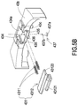
- FIG. 9 is a schematic view illustrating the exemplary structure of the strap of the wearable device according to an embodiment of the present invention.
- the strap 4 of the wearable device 2 comprises a flexible strap 41 , a connecting portion 42 and an adapter 43 .
- the connecting portion 42 and the adapter 43 are integrally formed.
- the adapter 43 comprises two ears 438 , and each of the ears 438 comprises a hole 4381 .
- One end of the flexible strap 41 comprises a tubular portion 411 , and two ends of the tubular portion 411 are respectively aligned with the holes 4381 of the two ears 438 .
- the strap 4 of the wearable device 2 further comprises a retractable rod 46 penetrating through the tubular portion 411 . The two ends of the retractable rod 46 are respectively aligned to and accommodated in the two holes 4381 of the two ears 438 , so as to assemble and disassemble the flexible strap 41 as required.
- the present invention provides the assembling structures of main body and strap of an improved wearable device that allow the main body and the strap of the wearable device to be securely connected with each other by a vertically-assembling manner, therefore the function module disposed on the strap could work continuously. Additionally, the main body and the strap could be easily detached from each other so that the main body or the strap could be replaced conveniently.
Abstract
Description
Claims (11)
Applications Claiming Priority (3)
| Application Number | Priority Date | Filing Date | Title |
|---|---|---|---|
| TW106145244A TWI640268B (en) | 2017-12-22 | 2017-12-22 | Wearable device |
| TW106145244 | 2017-12-22 | ||
| TW106145244A | 2017-12-22 |
Publications (2)
| Publication Number | Publication Date |
|---|---|
| US20190191828A1 US20190191828A1 (en) | 2019-06-27 |
| US10524549B2 true US10524549B2 (en) | 2020-01-07 |
Family
ID=65034492
Family Applications (1)
| Application Number | Title | Priority Date | Filing Date |
|---|---|---|---|
| US15/885,714 Expired - Fee Related US10524549B2 (en) | 2017-12-22 | 2018-01-31 | Wearable device |
Country Status (2)
| Country | Link |
|---|---|
| US (1) | US10524549B2 (en) |
| TW (1) | TWI640268B (en) |
Cited By (1)
| Publication number | Priority date | Publication date | Assignee | Title |
|---|---|---|---|---|
| US20220369770A1 (en) * | 2021-05-18 | 2022-11-24 | Beijing Xiaomi Mobile Software Co., Ltd. | Connection assembly and wearable device |
Families Citing this family (8)
| Publication number | Priority date | Publication date | Assignee | Title |
|---|---|---|---|---|
| USD749460S1 (en) * | 2014-08-11 | 2016-02-16 | Apple Inc. | Band attachment |
| CN109123933A (en) * | 2018-11-17 | 2019-01-04 | 东莞市亿丰钟表有限公司 | One kind is by hoodle snib formula watchband watchcase fixed structure processed |
| US11666124B2 (en) * | 2019-04-15 | 2023-06-06 | Apple Inc. | Watch band with braided strands |
| CN113031698B (en) * | 2019-12-25 | 2023-10-20 | 华为技术有限公司 | Wearable device |
| CN113311689B (en) * | 2020-02-26 | 2022-08-12 | Oppo广东移动通信有限公司 | Shell and preparation method thereof, watch body and wearable device |
| CN113558353B (en) * | 2021-07-22 | 2023-09-12 | 南昌逸勤科技有限公司 | Wearable equipment |
| CN215532167U (en) * | 2021-08-10 | 2022-01-18 | 深圳弘皇岚科技有限公司 | Positive and negative plug connector for watch |
| USD980111S1 (en) * | 2021-09-02 | 2023-03-07 | Changpei Bi | Watch band clasp |
Citations (10)
| Publication number | Priority date | Publication date | Assignee | Title |
|---|---|---|---|---|
| US3973099A (en) * | 1974-11-11 | 1976-08-03 | American Micro-Systems, Inc. | Push button switch for electronic watch |
| JP2002101923A (en) | 2000-09-27 | 2002-04-09 | Citizen Watch Co Ltd | Connecting structure of watch case to band |
| TW200724048A (en) | 2005-12-23 | 2007-07-01 | Swatch Group Man Serv Ag | Link element including a casing formed of a plate and a back plate |
| CN104414036A (en) | 2013-08-20 | 2015-03-18 | 昆达电脑科技(昆山)有限公司 | Watch |
| CN105768408A (en) | 2016-04-29 | 2016-07-20 | 歌尔声学股份有限公司 | Watch with watchband easy to assemble and disassemble |
| CN205696117U (en) | 2016-02-23 | 2016-11-23 | 华尔达(厦门)塑胶有限公司 | A kind of dial plate and the attachment structure of watchband |
| US9742085B2 (en) * | 2014-09-30 | 2017-08-22 | Apple Inc. | Portable electronic device connector |
| US20170265607A1 (en) | 2016-03-21 | 2017-09-21 | Apple Inc. | Attachment system for an electronic device |
| US10042326B2 (en) * | 2015-12-15 | 2018-08-07 | Omega Sa | Watch bracelet |
| US10085523B2 (en) * | 2014-08-11 | 2018-10-02 | Apple Inc. | Attachment system for an electronic device |
-
2017
- 2017-12-22 TW TW106145244A patent/TWI640268B/en not_active IP Right Cessation
-
2018
- 2018-01-31 US US15/885,714 patent/US10524549B2/en not_active Expired - Fee Related
Patent Citations (10)
| Publication number | Priority date | Publication date | Assignee | Title |
|---|---|---|---|---|
| US3973099A (en) * | 1974-11-11 | 1976-08-03 | American Micro-Systems, Inc. | Push button switch for electronic watch |
| JP2002101923A (en) | 2000-09-27 | 2002-04-09 | Citizen Watch Co Ltd | Connecting structure of watch case to band |
| TW200724048A (en) | 2005-12-23 | 2007-07-01 | Swatch Group Man Serv Ag | Link element including a casing formed of a plate and a back plate |
| CN104414036A (en) | 2013-08-20 | 2015-03-18 | 昆达电脑科技(昆山)有限公司 | Watch |
| US10085523B2 (en) * | 2014-08-11 | 2018-10-02 | Apple Inc. | Attachment system for an electronic device |
| US9742085B2 (en) * | 2014-09-30 | 2017-08-22 | Apple Inc. | Portable electronic device connector |
| US10042326B2 (en) * | 2015-12-15 | 2018-08-07 | Omega Sa | Watch bracelet |
| CN205696117U (en) | 2016-02-23 | 2016-11-23 | 华尔达(厦门)塑胶有限公司 | A kind of dial plate and the attachment structure of watchband |
| US20170265607A1 (en) | 2016-03-21 | 2017-09-21 | Apple Inc. | Attachment system for an electronic device |
| CN105768408A (en) | 2016-04-29 | 2016-07-20 | 歌尔声学股份有限公司 | Watch with watchband easy to assemble and disassemble |
Non-Patent Citations (1)
| Title |
|---|
| English Machine Translation of CN205696117 (Year: 2016). * |
Cited By (2)
| Publication number | Priority date | Publication date | Assignee | Title |
|---|---|---|---|---|
| US20220369770A1 (en) * | 2021-05-18 | 2022-11-24 | Beijing Xiaomi Mobile Software Co., Ltd. | Connection assembly and wearable device |
| US11559119B2 (en) * | 2021-05-18 | 2023-01-24 | Beijing Xiaomi Mobile Software Co., Ltd. | Connection assembly and wearable device |
Also Published As
| Publication number | Publication date |
|---|---|
| TWI640268B (en) | 2018-11-11 |
| US20190191828A1 (en) | 2019-06-27 |
| TW201927195A (en) | 2019-07-16 |
Similar Documents
| Publication | Publication Date | Title |
|---|---|---|
| US10524549B2 (en) | Wearable device | |
| US7118399B1 (en) | Electronic device with replaceable plug | |
| US20110182019A1 (en) | Display structure of slip-cover-hinge electronic device | |
| US20110228491A1 (en) | Sliding electronic apparatus | |
| KR101390191B1 (en) | Electronic device with capacity of electrostatic discharge | |
| JP2011242879A (en) | Connector | |
| US9930781B2 (en) | Receptacle assembly and module assembly | |
| US9418036B2 (en) | Data terminal with a connection structure of USB interface | |
| JP5668160B1 (en) | connector | |
| JP2005157790A (en) | Electronic device | |
| US7780458B2 (en) | Cable plug assembly with internal circuit board | |
| KR101251670B1 (en) | Mobile phone having separation type camera module | |
| JP4133431B2 (en) | Electrical connection plug | |
| US7452231B2 (en) | Portable electronic device | |
| US20190381308A1 (en) | Low-frequency treatment device, body for low-frequency treatment device, and combination of pad and holder for low-frequency treatment device | |
| US9755355B2 (en) | Connection module for a portable electronic device | |
| US20180295951A1 (en) | Portable electronic device with strap | |
| US20070215450A1 (en) | Slide switch | |
| CN109963415B (en) | Wearable device | |
| CN106653414B (en) | Improved switch wiring device | |
| KR20170112307A (en) | Connector for flexible circuit cable | |
| EP2942836A1 (en) | Terminal block | |
| US6719584B1 (en) | Watertight flexible connector | |
| JP5919340B2 (en) | Plug connector | |
| KR200488571Y1 (en) | Multi-tap |
Legal Events
| Date | Code | Title | Description |
|---|---|---|---|
| FEPP | Fee payment procedure |
Free format text: ENTITY STATUS SET TO UNDISCOUNTED (ORIGINAL EVENT CODE: BIG.); ENTITY STATUS OF PATENT OWNER: LARGE ENTITY |
|
| AS | Assignment |
Owner name: COMPAL ELECTRONICS, INC, TAIWAN Free format text: ASSIGNMENT OF ASSIGNORS INTEREST;ASSIGNORS:WANG, TSUNG-SUNG;YANG, KUN-CHEN;YU, SHIH-HAI;REEL/FRAME:044804/0058 Effective date: 20180104 |
|
| STPP | Information on status: patent application and granting procedure in general |
Free format text: NON FINAL ACTION MAILED |
|
| STPP | Information on status: patent application and granting procedure in general |
Free format text: NOTICE OF ALLOWANCE MAILED -- APPLICATION RECEIVED IN OFFICE OF PUBLICATIONS |
|
| ZAAA | Notice of allowance and fees due |
Free format text: ORIGINAL CODE: NOA |
|
| ZAAB | Notice of allowance mailed |
Free format text: ORIGINAL CODE: MN/=. |
|
| STPP | Information on status: patent application and granting procedure in general |
Free format text: PUBLICATIONS -- ISSUE FEE PAYMENT VERIFIED |
|
| STCF | Information on status: patent grant |
Free format text: PATENTED CASE |
|
| FEPP | Fee payment procedure |
Free format text: MAINTENANCE FEE REMINDER MAILED (ORIGINAL EVENT CODE: REM.); ENTITY STATUS OF PATENT OWNER: LARGE ENTITY |
|
| LAPS | Lapse for failure to pay maintenance fees |
Free format text: PATENT EXPIRED FOR FAILURE TO PAY MAINTENANCE FEES (ORIGINAL EVENT CODE: EXP.); ENTITY STATUS OF PATENT OWNER: LARGE ENTITY |
|
| STCH | Information on status: patent discontinuation |
Free format text: PATENT EXPIRED DUE TO NONPAYMENT OF MAINTENANCE FEES UNDER 37 CFR 1.362 |
|
| FP | Lapsed due to failure to pay maintenance fee |
Effective date: 20240107 |