US10520249B2 - Process and apparatus for processing a hydrocarbon gas stream - Google Patents

Process and apparatus for processing a hydrocarbon gas stream Download PDF

Info

Publication number
US10520249B2
US10520249B2 US15/353,603 US201615353603A US10520249B2 US 10520249 B2 US10520249 B2 US 10520249B2 US 201615353603 A US201615353603 A US 201615353603A US 10520249 B2 US10520249 B2 US 10520249B2
Authority
US
United States
Prior art keywords
gas
stream
components
feed
hydrocarbon
Prior art date
Legal status (The legal status is an assumption and is not a legal conclusion. Google has not performed a legal analysis and makes no representation as to the accuracy of the status listed.)
Expired - Fee Related
Application number
US15/353,603
Other versions
US20170211877A1 (en
Inventor
Stephen Craig Horne
Current Assignee (The listed assignees may be inaccurate. Google has not performed a legal analysis and makes no representation or warranty as to the accuracy of the list.)
Ovintiv Canada ULC
Original Assignee
Encana Corp
Priority date (The priority date is an assumption and is not a legal conclusion. Google has not performed a legal analysis and makes no representation as to the accuracy of the date listed.)
Filing date
Publication date
Application filed by Encana Corp filed Critical Encana Corp
Priority to US15/353,603 priority Critical patent/US10520249B2/en
Assigned to ENCANA CORPORATION reassignment ENCANA CORPORATION ASSIGNMENT OF ASSIGNORS INTEREST (SEE DOCUMENT FOR DETAILS). Assignors: HORNE, STEPHEN CRAIG
Publication of US20170211877A1 publication Critical patent/US20170211877A1/en
Application granted granted Critical
Publication of US10520249B2 publication Critical patent/US10520249B2/en
Assigned to OVINTIV CANADA ULC reassignment OVINTIV CANADA ULC CHANGE OF NAME (SEE DOCUMENT FOR DETAILS). Assignors: ENCANA CORPORATION
Expired - Fee Related legal-status Critical Current
Anticipated expiration legal-status Critical

Links

Images

Classifications

    • FMECHANICAL ENGINEERING; LIGHTING; HEATING; WEAPONS; BLASTING
    • F25REFRIGERATION OR COOLING; COMBINED HEATING AND REFRIGERATION SYSTEMS; HEAT PUMP SYSTEMS; MANUFACTURE OR STORAGE OF ICE; LIQUEFACTION SOLIDIFICATION OF GASES
    • F25JLIQUEFACTION, SOLIDIFICATION OR SEPARATION OF GASES OR GASEOUS OR LIQUEFIED GASEOUS MIXTURES BY PRESSURE AND COLD TREATMENT OR BY BRINGING THEM INTO THE SUPERCRITICAL STATE
    • F25J3/00Processes or apparatus for separating the constituents of gaseous or liquefied gaseous mixtures involving the use of liquefaction or solidification
    • F25J3/02Processes or apparatus for separating the constituents of gaseous or liquefied gaseous mixtures involving the use of liquefaction or solidification by rectification, i.e. by continuous interchange of heat and material between a vapour stream and a liquid stream
    • F25J3/0204Processes or apparatus for separating the constituents of gaseous or liquefied gaseous mixtures involving the use of liquefaction or solidification by rectification, i.e. by continuous interchange of heat and material between a vapour stream and a liquid stream characterised by the feed stream
    • F25J3/0209Natural gas or substitute natural gas
    • CCHEMISTRY; METALLURGY
    • C10PETROLEUM, GAS OR COKE INDUSTRIES; TECHNICAL GASES CONTAINING CARBON MONOXIDE; FUELS; LUBRICANTS; PEAT
    • C10GCRACKING HYDROCARBON OILS; PRODUCTION OF LIQUID HYDROCARBON MIXTURES, e.g. BY DESTRUCTIVE HYDROGENATION, OLIGOMERISATION, POLYMERISATION; RECOVERY OF HYDROCARBON OILS FROM OIL-SHALE, OIL-SAND, OR GASES; REFINING MIXTURES MAINLY CONSISTING OF HYDROCARBONS; REFORMING OF NAPHTHA; MINERAL WAXES
    • C10G5/00Recovery of liquid hydrocarbon mixtures from gases, e.g. natural gas
    • C10G5/06Recovery of liquid hydrocarbon mixtures from gases, e.g. natural gas by cooling or compressing
    • CCHEMISTRY; METALLURGY
    • C10PETROLEUM, GAS OR COKE INDUSTRIES; TECHNICAL GASES CONTAINING CARBON MONOXIDE; FUELS; LUBRICANTS; PEAT
    • C10GCRACKING HYDROCARBON OILS; PRODUCTION OF LIQUID HYDROCARBON MIXTURES, e.g. BY DESTRUCTIVE HYDROGENATION, OLIGOMERISATION, POLYMERISATION; RECOVERY OF HYDROCARBON OILS FROM OIL-SHALE, OIL-SAND, OR GASES; REFINING MIXTURES MAINLY CONSISTING OF HYDROCARBONS; REFORMING OF NAPHTHA; MINERAL WAXES
    • C10G70/00Working-up undefined normally gaseous mixtures obtained by processes covered by groups C10G9/00, C10G11/00, C10G15/00, C10G47/00, C10G51/00
    • C10G70/04Working-up undefined normally gaseous mixtures obtained by processes covered by groups C10G9/00, C10G11/00, C10G15/00, C10G47/00, C10G51/00 by physical processes
    • CCHEMISTRY; METALLURGY
    • C10PETROLEUM, GAS OR COKE INDUSTRIES; TECHNICAL GASES CONTAINING CARBON MONOXIDE; FUELS; LUBRICANTS; PEAT
    • C10LFUELS NOT OTHERWISE PROVIDED FOR; NATURAL GAS; SYNTHETIC NATURAL GAS OBTAINED BY PROCESSES NOT COVERED BY SUBCLASSES C10G, C10K; LIQUEFIED PETROLEUM GAS; ADDING MATERIALS TO FUELS OR FIRES TO REDUCE SMOKE OR UNDESIRABLE DEPOSITS OR TO FACILITATE SOOT REMOVAL; FIRELIGHTERS
    • C10L3/00Gaseous fuels; Natural gas; Synthetic natural gas obtained by processes not covered by subclass C10G, C10K; Liquefied petroleum gas
    • C10L3/06Natural gas; Synthetic natural gas obtained by processes not covered by C10G, C10K3/02 or C10K3/04
    • C10L3/10Working-up natural gas or synthetic natural gas
    • CCHEMISTRY; METALLURGY
    • C10PETROLEUM, GAS OR COKE INDUSTRIES; TECHNICAL GASES CONTAINING CARBON MONOXIDE; FUELS; LUBRICANTS; PEAT
    • C10LFUELS NOT OTHERWISE PROVIDED FOR; NATURAL GAS; SYNTHETIC NATURAL GAS OBTAINED BY PROCESSES NOT COVERED BY SUBCLASSES C10G, C10K; LIQUEFIED PETROLEUM GAS; ADDING MATERIALS TO FUELS OR FIRES TO REDUCE SMOKE OR UNDESIRABLE DEPOSITS OR TO FACILITATE SOOT REMOVAL; FIRELIGHTERS
    • C10L3/00Gaseous fuels; Natural gas; Synthetic natural gas obtained by processes not covered by subclass C10G, C10K; Liquefied petroleum gas
    • C10L3/12Liquefied petroleum gas
    • FMECHANICAL ENGINEERING; LIGHTING; HEATING; WEAPONS; BLASTING
    • F25REFRIGERATION OR COOLING; COMBINED HEATING AND REFRIGERATION SYSTEMS; HEAT PUMP SYSTEMS; MANUFACTURE OR STORAGE OF ICE; LIQUEFACTION SOLIDIFICATION OF GASES
    • F25JLIQUEFACTION, SOLIDIFICATION OR SEPARATION OF GASES OR GASEOUS OR LIQUEFIED GASEOUS MIXTURES BY PRESSURE AND COLD TREATMENT OR BY BRINGING THEM INTO THE SUPERCRITICAL STATE
    • F25J1/00Processes or apparatus for liquefying or solidifying gases or gaseous mixtures
    • F25J1/0002Processes or apparatus for liquefying or solidifying gases or gaseous mixtures characterised by the fluid to be liquefied
    • F25J1/0022Hydrocarbons, e.g. natural gas
    • FMECHANICAL ENGINEERING; LIGHTING; HEATING; WEAPONS; BLASTING
    • F25REFRIGERATION OR COOLING; COMBINED HEATING AND REFRIGERATION SYSTEMS; HEAT PUMP SYSTEMS; MANUFACTURE OR STORAGE OF ICE; LIQUEFACTION SOLIDIFICATION OF GASES
    • F25JLIQUEFACTION, SOLIDIFICATION OR SEPARATION OF GASES OR GASEOUS OR LIQUEFIED GASEOUS MIXTURES BY PRESSURE AND COLD TREATMENT OR BY BRINGING THEM INTO THE SUPERCRITICAL STATE
    • F25J3/00Processes or apparatus for separating the constituents of gaseous or liquefied gaseous mixtures involving the use of liquefaction or solidification
    • F25J3/02Processes or apparatus for separating the constituents of gaseous or liquefied gaseous mixtures involving the use of liquefaction or solidification by rectification, i.e. by continuous interchange of heat and material between a vapour stream and a liquid stream
    • F25J3/0204Processes or apparatus for separating the constituents of gaseous or liquefied gaseous mixtures involving the use of liquefaction or solidification by rectification, i.e. by continuous interchange of heat and material between a vapour stream and a liquid stream characterised by the feed stream
    • F25J3/0219Refinery gas, cracking gas, coke oven gas, gaseous mixtures containing aliphatic unsaturated CnHm or gaseous mixtures of undefined nature
    • FMECHANICAL ENGINEERING; LIGHTING; HEATING; WEAPONS; BLASTING
    • F25REFRIGERATION OR COOLING; COMBINED HEATING AND REFRIGERATION SYSTEMS; HEAT PUMP SYSTEMS; MANUFACTURE OR STORAGE OF ICE; LIQUEFACTION SOLIDIFICATION OF GASES
    • F25JLIQUEFACTION, SOLIDIFICATION OR SEPARATION OF GASES OR GASEOUS OR LIQUEFIED GASEOUS MIXTURES BY PRESSURE AND COLD TREATMENT OR BY BRINGING THEM INTO THE SUPERCRITICAL STATE
    • F25J3/00Processes or apparatus for separating the constituents of gaseous or liquefied gaseous mixtures involving the use of liquefaction or solidification
    • F25J3/02Processes or apparatus for separating the constituents of gaseous or liquefied gaseous mixtures involving the use of liquefaction or solidification by rectification, i.e. by continuous interchange of heat and material between a vapour stream and a liquid stream
    • F25J3/0204Processes or apparatus for separating the constituents of gaseous or liquefied gaseous mixtures involving the use of liquefaction or solidification by rectification, i.e. by continuous interchange of heat and material between a vapour stream and a liquid stream characterised by the feed stream
    • F25J3/0223H2/CO mixtures, i.e. synthesis gas; Water gas or shifted synthesis gas
    • FMECHANICAL ENGINEERING; LIGHTING; HEATING; WEAPONS; BLASTING
    • F25REFRIGERATION OR COOLING; COMBINED HEATING AND REFRIGERATION SYSTEMS; HEAT PUMP SYSTEMS; MANUFACTURE OR STORAGE OF ICE; LIQUEFACTION SOLIDIFICATION OF GASES
    • F25JLIQUEFACTION, SOLIDIFICATION OR SEPARATION OF GASES OR GASEOUS OR LIQUEFIED GASEOUS MIXTURES BY PRESSURE AND COLD TREATMENT OR BY BRINGING THEM INTO THE SUPERCRITICAL STATE
    • F25J3/00Processes or apparatus for separating the constituents of gaseous or liquefied gaseous mixtures involving the use of liquefaction or solidification
    • F25J3/02Processes or apparatus for separating the constituents of gaseous or liquefied gaseous mixtures involving the use of liquefaction or solidification by rectification, i.e. by continuous interchange of heat and material between a vapour stream and a liquid stream
    • F25J3/0228Processes or apparatus for separating the constituents of gaseous or liquefied gaseous mixtures involving the use of liquefaction or solidification by rectification, i.e. by continuous interchange of heat and material between a vapour stream and a liquid stream characterised by the separated product stream
    • F25J3/0233Processes or apparatus for separating the constituents of gaseous or liquefied gaseous mixtures involving the use of liquefaction or solidification by rectification, i.e. by continuous interchange of heat and material between a vapour stream and a liquid stream characterised by the separated product stream separation of CnHm with 1 carbon atom or more
    • FMECHANICAL ENGINEERING; LIGHTING; HEATING; WEAPONS; BLASTING
    • F25REFRIGERATION OR COOLING; COMBINED HEATING AND REFRIGERATION SYSTEMS; HEAT PUMP SYSTEMS; MANUFACTURE OR STORAGE OF ICE; LIQUEFACTION SOLIDIFICATION OF GASES
    • F25JLIQUEFACTION, SOLIDIFICATION OR SEPARATION OF GASES OR GASEOUS OR LIQUEFIED GASEOUS MIXTURES BY PRESSURE AND COLD TREATMENT OR BY BRINGING THEM INTO THE SUPERCRITICAL STATE
    • F25J3/00Processes or apparatus for separating the constituents of gaseous or liquefied gaseous mixtures involving the use of liquefaction or solidification
    • F25J3/02Processes or apparatus for separating the constituents of gaseous or liquefied gaseous mixtures involving the use of liquefaction or solidification by rectification, i.e. by continuous interchange of heat and material between a vapour stream and a liquid stream
    • F25J3/0228Processes or apparatus for separating the constituents of gaseous or liquefied gaseous mixtures involving the use of liquefaction or solidification by rectification, i.e. by continuous interchange of heat and material between a vapour stream and a liquid stream characterised by the separated product stream
    • F25J3/0238Processes or apparatus for separating the constituents of gaseous or liquefied gaseous mixtures involving the use of liquefaction or solidification by rectification, i.e. by continuous interchange of heat and material between a vapour stream and a liquid stream characterised by the separated product stream separation of CnHm with 2 carbon atoms or more
    • FMECHANICAL ENGINEERING; LIGHTING; HEATING; WEAPONS; BLASTING
    • F25REFRIGERATION OR COOLING; COMBINED HEATING AND REFRIGERATION SYSTEMS; HEAT PUMP SYSTEMS; MANUFACTURE OR STORAGE OF ICE; LIQUEFACTION SOLIDIFICATION OF GASES
    • F25JLIQUEFACTION, SOLIDIFICATION OR SEPARATION OF GASES OR GASEOUS OR LIQUEFIED GASEOUS MIXTURES BY PRESSURE AND COLD TREATMENT OR BY BRINGING THEM INTO THE SUPERCRITICAL STATE
    • F25J3/00Processes or apparatus for separating the constituents of gaseous or liquefied gaseous mixtures involving the use of liquefaction or solidification
    • F25J3/02Processes or apparatus for separating the constituents of gaseous or liquefied gaseous mixtures involving the use of liquefaction or solidification by rectification, i.e. by continuous interchange of heat and material between a vapour stream and a liquid stream
    • F25J3/0228Processes or apparatus for separating the constituents of gaseous or liquefied gaseous mixtures involving the use of liquefaction or solidification by rectification, i.e. by continuous interchange of heat and material between a vapour stream and a liquid stream characterised by the separated product stream
    • F25J3/0242Processes or apparatus for separating the constituents of gaseous or liquefied gaseous mixtures involving the use of liquefaction or solidification by rectification, i.e. by continuous interchange of heat and material between a vapour stream and a liquid stream characterised by the separated product stream separation of CnHm with 3 carbon atoms or more
    • FMECHANICAL ENGINEERING; LIGHTING; HEATING; WEAPONS; BLASTING
    • F25REFRIGERATION OR COOLING; COMBINED HEATING AND REFRIGERATION SYSTEMS; HEAT PUMP SYSTEMS; MANUFACTURE OR STORAGE OF ICE; LIQUEFACTION SOLIDIFICATION OF GASES
    • F25JLIQUEFACTION, SOLIDIFICATION OR SEPARATION OF GASES OR GASEOUS OR LIQUEFIED GASEOUS MIXTURES BY PRESSURE AND COLD TREATMENT OR BY BRINGING THEM INTO THE SUPERCRITICAL STATE
    • F25J3/00Processes or apparatus for separating the constituents of gaseous or liquefied gaseous mixtures involving the use of liquefaction or solidification
    • F25J3/02Processes or apparatus for separating the constituents of gaseous or liquefied gaseous mixtures involving the use of liquefaction or solidification by rectification, i.e. by continuous interchange of heat and material between a vapour stream and a liquid stream
    • F25J3/0228Processes or apparatus for separating the constituents of gaseous or liquefied gaseous mixtures involving the use of liquefaction or solidification by rectification, i.e. by continuous interchange of heat and material between a vapour stream and a liquid stream characterised by the separated product stream
    • F25J3/0247Processes or apparatus for separating the constituents of gaseous or liquefied gaseous mixtures involving the use of liquefaction or solidification by rectification, i.e. by continuous interchange of heat and material between a vapour stream and a liquid stream characterised by the separated product stream separation of CnHm with 4 carbon atoms or more
    • FMECHANICAL ENGINEERING; LIGHTING; HEATING; WEAPONS; BLASTING
    • F25REFRIGERATION OR COOLING; COMBINED HEATING AND REFRIGERATION SYSTEMS; HEAT PUMP SYSTEMS; MANUFACTURE OR STORAGE OF ICE; LIQUEFACTION SOLIDIFICATION OF GASES
    • F25JLIQUEFACTION, SOLIDIFICATION OR SEPARATION OF GASES OR GASEOUS OR LIQUEFIED GASEOUS MIXTURES BY PRESSURE AND COLD TREATMENT OR BY BRINGING THEM INTO THE SUPERCRITICAL STATE
    • F25J3/00Processes or apparatus for separating the constituents of gaseous or liquefied gaseous mixtures involving the use of liquefaction or solidification
    • F25J3/02Processes or apparatus for separating the constituents of gaseous or liquefied gaseous mixtures involving the use of liquefaction or solidification by rectification, i.e. by continuous interchange of heat and material between a vapour stream and a liquid stream
    • F25J3/0295Start-up or control of the process; Details of the apparatus used, e.g. sieve plates, packings
    • CCHEMISTRY; METALLURGY
    • C10PETROLEUM, GAS OR COKE INDUSTRIES; TECHNICAL GASES CONTAINING CARBON MONOXIDE; FUELS; LUBRICANTS; PEAT
    • C10LFUELS NOT OTHERWISE PROVIDED FOR; NATURAL GAS; SYNTHETIC NATURAL GAS OBTAINED BY PROCESSES NOT COVERED BY SUBCLASSES C10G, C10K; LIQUEFIED PETROLEUM GAS; ADDING MATERIALS TO FUELS OR FIRES TO REDUCE SMOKE OR UNDESIRABLE DEPOSITS OR TO FACILITATE SOOT REMOVAL; FIRELIGHTERS
    • C10L2290/00Fuel preparation or upgrading, processes or apparatus therefore, comprising specific process steps or apparatus units
    • C10L2290/06Heat exchange, direct or indirect
    • CCHEMISTRY; METALLURGY
    • C10PETROLEUM, GAS OR COKE INDUSTRIES; TECHNICAL GASES CONTAINING CARBON MONOXIDE; FUELS; LUBRICANTS; PEAT
    • C10LFUELS NOT OTHERWISE PROVIDED FOR; NATURAL GAS; SYNTHETIC NATURAL GAS OBTAINED BY PROCESSES NOT COVERED BY SUBCLASSES C10G, C10K; LIQUEFIED PETROLEUM GAS; ADDING MATERIALS TO FUELS OR FIRES TO REDUCE SMOKE OR UNDESIRABLE DEPOSITS OR TO FACILITATE SOOT REMOVAL; FIRELIGHTERS
    • C10L2290/00Fuel preparation or upgrading, processes or apparatus therefore, comprising specific process steps or apparatus units
    • C10L2290/10Recycling of a stream within the process or apparatus to reuse elsewhere therein
    • CCHEMISTRY; METALLURGY
    • C10PETROLEUM, GAS OR COKE INDUSTRIES; TECHNICAL GASES CONTAINING CARBON MONOXIDE; FUELS; LUBRICANTS; PEAT
    • C10LFUELS NOT OTHERWISE PROVIDED FOR; NATURAL GAS; SYNTHETIC NATURAL GAS OBTAINED BY PROCESSES NOT COVERED BY SUBCLASSES C10G, C10K; LIQUEFIED PETROLEUM GAS; ADDING MATERIALS TO FUELS OR FIRES TO REDUCE SMOKE OR UNDESIRABLE DEPOSITS OR TO FACILITATE SOOT REMOVAL; FIRELIGHTERS
    • C10L2290/00Fuel preparation or upgrading, processes or apparatus therefore, comprising specific process steps or apparatus units
    • C10L2290/46Compressors or pumps
    • CCHEMISTRY; METALLURGY
    • C10PETROLEUM, GAS OR COKE INDUSTRIES; TECHNICAL GASES CONTAINING CARBON MONOXIDE; FUELS; LUBRICANTS; PEAT
    • C10LFUELS NOT OTHERWISE PROVIDED FOR; NATURAL GAS; SYNTHETIC NATURAL GAS OBTAINED BY PROCESSES NOT COVERED BY SUBCLASSES C10G, C10K; LIQUEFIED PETROLEUM GAS; ADDING MATERIALS TO FUELS OR FIRES TO REDUCE SMOKE OR UNDESIRABLE DEPOSITS OR TO FACILITATE SOOT REMOVAL; FIRELIGHTERS
    • C10L2290/00Fuel preparation or upgrading, processes or apparatus therefore, comprising specific process steps or apparatus units
    • C10L2290/48Expanders, e.g. throttles or flash tanks
    • CCHEMISTRY; METALLURGY
    • C10PETROLEUM, GAS OR COKE INDUSTRIES; TECHNICAL GASES CONTAINING CARBON MONOXIDE; FUELS; LUBRICANTS; PEAT
    • C10LFUELS NOT OTHERWISE PROVIDED FOR; NATURAL GAS; SYNTHETIC NATURAL GAS OBTAINED BY PROCESSES NOT COVERED BY SUBCLASSES C10G, C10K; LIQUEFIED PETROLEUM GAS; ADDING MATERIALS TO FUELS OR FIRES TO REDUCE SMOKE OR UNDESIRABLE DEPOSITS OR TO FACILITATE SOOT REMOVAL; FIRELIGHTERS
    • C10L2290/00Fuel preparation or upgrading, processes or apparatus therefore, comprising specific process steps or apparatus units
    • C10L2290/54Specific separation steps for separating fractions, components or impurities during preparation or upgrading of a fuel
    • C10L2290/541Absorption of impurities during preparation or upgrading of a fuel
    • CCHEMISTRY; METALLURGY
    • C10PETROLEUM, GAS OR COKE INDUSTRIES; TECHNICAL GASES CONTAINING CARBON MONOXIDE; FUELS; LUBRICANTS; PEAT
    • C10LFUELS NOT OTHERWISE PROVIDED FOR; NATURAL GAS; SYNTHETIC NATURAL GAS OBTAINED BY PROCESSES NOT COVERED BY SUBCLASSES C10G, C10K; LIQUEFIED PETROLEUM GAS; ADDING MATERIALS TO FUELS OR FIRES TO REDUCE SMOKE OR UNDESIRABLE DEPOSITS OR TO FACILITATE SOOT REMOVAL; FIRELIGHTERS
    • C10L2290/00Fuel preparation or upgrading, processes or apparatus therefore, comprising specific process steps or apparatus units
    • C10L2290/54Specific separation steps for separating fractions, components or impurities during preparation or upgrading of a fuel
    • C10L2290/542Adsorption of impurities during preparation or upgrading of a fuel
    • CCHEMISTRY; METALLURGY
    • C10PETROLEUM, GAS OR COKE INDUSTRIES; TECHNICAL GASES CONTAINING CARBON MONOXIDE; FUELS; LUBRICANTS; PEAT
    • C10LFUELS NOT OTHERWISE PROVIDED FOR; NATURAL GAS; SYNTHETIC NATURAL GAS OBTAINED BY PROCESSES NOT COVERED BY SUBCLASSES C10G, C10K; LIQUEFIED PETROLEUM GAS; ADDING MATERIALS TO FUELS OR FIRES TO REDUCE SMOKE OR UNDESIRABLE DEPOSITS OR TO FACILITATE SOOT REMOVAL; FIRELIGHTERS
    • C10L2290/00Fuel preparation or upgrading, processes or apparatus therefore, comprising specific process steps or apparatus units
    • C10L2290/54Specific separation steps for separating fractions, components or impurities during preparation or upgrading of a fuel
    • C10L2290/545Washing, scrubbing, stripping, scavenging for separating fractions, components or impurities during preparation or upgrading of a fuel
    • FMECHANICAL ENGINEERING; LIGHTING; HEATING; WEAPONS; BLASTING
    • F25REFRIGERATION OR COOLING; COMBINED HEATING AND REFRIGERATION SYSTEMS; HEAT PUMP SYSTEMS; MANUFACTURE OR STORAGE OF ICE; LIQUEFACTION SOLIDIFICATION OF GASES
    • F25JLIQUEFACTION, SOLIDIFICATION OR SEPARATION OF GASES OR GASEOUS OR LIQUEFIED GASEOUS MIXTURES BY PRESSURE AND COLD TREATMENT OR BY BRINGING THEM INTO THE SUPERCRITICAL STATE
    • F25J2200/00Processes or apparatus using separation by rectification
    • F25J2200/02Processes or apparatus using separation by rectification in a single pressure main column system
    • FMECHANICAL ENGINEERING; LIGHTING; HEATING; WEAPONS; BLASTING
    • F25REFRIGERATION OR COOLING; COMBINED HEATING AND REFRIGERATION SYSTEMS; HEAT PUMP SYSTEMS; MANUFACTURE OR STORAGE OF ICE; LIQUEFACTION SOLIDIFICATION OF GASES
    • F25JLIQUEFACTION, SOLIDIFICATION OR SEPARATION OF GASES OR GASEOUS OR LIQUEFIED GASEOUS MIXTURES BY PRESSURE AND COLD TREATMENT OR BY BRINGING THEM INTO THE SUPERCRITICAL STATE
    • F25J2200/00Processes or apparatus using separation by rectification
    • F25J2200/04Processes or apparatus using separation by rectification in a dual pressure main column system
    • FMECHANICAL ENGINEERING; LIGHTING; HEATING; WEAPONS; BLASTING
    • F25REFRIGERATION OR COOLING; COMBINED HEATING AND REFRIGERATION SYSTEMS; HEAT PUMP SYSTEMS; MANUFACTURE OR STORAGE OF ICE; LIQUEFACTION SOLIDIFICATION OF GASES
    • F25JLIQUEFACTION, SOLIDIFICATION OR SEPARATION OF GASES OR GASEOUS OR LIQUEFIED GASEOUS MIXTURES BY PRESSURE AND COLD TREATMENT OR BY BRINGING THEM INTO THE SUPERCRITICAL STATE
    • F25J2200/00Processes or apparatus using separation by rectification
    • F25J2200/38Processes or apparatus using separation by rectification using pre-separation or distributed distillation before a main column system, e.g. in a at least a double column system
    • FMECHANICAL ENGINEERING; LIGHTING; HEATING; WEAPONS; BLASTING
    • F25REFRIGERATION OR COOLING; COMBINED HEATING AND REFRIGERATION SYSTEMS; HEAT PUMP SYSTEMS; MANUFACTURE OR STORAGE OF ICE; LIQUEFACTION SOLIDIFICATION OF GASES
    • F25JLIQUEFACTION, SOLIDIFICATION OR SEPARATION OF GASES OR GASEOUS OR LIQUEFIED GASEOUS MIXTURES BY PRESSURE AND COLD TREATMENT OR BY BRINGING THEM INTO THE SUPERCRITICAL STATE
    • F25J2200/00Processes or apparatus using separation by rectification
    • F25J2200/70Refluxing the column with a condensed part of the feed stream, i.e. fractionator top is stripped or self-rectified
    • FMECHANICAL ENGINEERING; LIGHTING; HEATING; WEAPONS; BLASTING
    • F25REFRIGERATION OR COOLING; COMBINED HEATING AND REFRIGERATION SYSTEMS; HEAT PUMP SYSTEMS; MANUFACTURE OR STORAGE OF ICE; LIQUEFACTION SOLIDIFICATION OF GASES
    • F25JLIQUEFACTION, SOLIDIFICATION OR SEPARATION OF GASES OR GASEOUS OR LIQUEFIED GASEOUS MIXTURES BY PRESSURE AND COLD TREATMENT OR BY BRINGING THEM INTO THE SUPERCRITICAL STATE
    • F25J2200/00Processes or apparatus using separation by rectification
    • F25J2200/74Refluxing the column with at least a part of the partially condensed overhead gas
    • FMECHANICAL ENGINEERING; LIGHTING; HEATING; WEAPONS; BLASTING
    • F25REFRIGERATION OR COOLING; COMBINED HEATING AND REFRIGERATION SYSTEMS; HEAT PUMP SYSTEMS; MANUFACTURE OR STORAGE OF ICE; LIQUEFACTION SOLIDIFICATION OF GASES
    • F25JLIQUEFACTION, SOLIDIFICATION OR SEPARATION OF GASES OR GASEOUS OR LIQUEFIED GASEOUS MIXTURES BY PRESSURE AND COLD TREATMENT OR BY BRINGING THEM INTO THE SUPERCRITICAL STATE
    • F25J2205/00Processes or apparatus using other separation and/or other processing means
    • F25J2205/60Processes or apparatus using other separation and/or other processing means using adsorption on solid adsorbents, e.g. by temperature-swing adsorption [TSA] at the hot or cold end
    • FMECHANICAL ENGINEERING; LIGHTING; HEATING; WEAPONS; BLASTING
    • F25REFRIGERATION OR COOLING; COMBINED HEATING AND REFRIGERATION SYSTEMS; HEAT PUMP SYSTEMS; MANUFACTURE OR STORAGE OF ICE; LIQUEFACTION SOLIDIFICATION OF GASES
    • F25JLIQUEFACTION, SOLIDIFICATION OR SEPARATION OF GASES OR GASEOUS OR LIQUEFIED GASEOUS MIXTURES BY PRESSURE AND COLD TREATMENT OR BY BRINGING THEM INTO THE SUPERCRITICAL STATE
    • F25J2210/00Processes characterised by the type or other details of the feed stream
    • F25J2210/04Mixing or blending of fluids with the feed stream
    • FMECHANICAL ENGINEERING; LIGHTING; HEATING; WEAPONS; BLASTING
    • F25REFRIGERATION OR COOLING; COMBINED HEATING AND REFRIGERATION SYSTEMS; HEAT PUMP SYSTEMS; MANUFACTURE OR STORAGE OF ICE; LIQUEFACTION SOLIDIFICATION OF GASES
    • F25JLIQUEFACTION, SOLIDIFICATION OR SEPARATION OF GASES OR GASEOUS OR LIQUEFIED GASEOUS MIXTURES BY PRESSURE AND COLD TREATMENT OR BY BRINGING THEM INTO THE SUPERCRITICAL STATE
    • F25J2245/00Processes or apparatus involving steps for recycling of process streams
    • F25J2245/02Recycle of a stream in general, e.g. a by-pass stream
    • FMECHANICAL ENGINEERING; LIGHTING; HEATING; WEAPONS; BLASTING
    • F25REFRIGERATION OR COOLING; COMBINED HEATING AND REFRIGERATION SYSTEMS; HEAT PUMP SYSTEMS; MANUFACTURE OR STORAGE OF ICE; LIQUEFACTION SOLIDIFICATION OF GASES
    • F25JLIQUEFACTION, SOLIDIFICATION OR SEPARATION OF GASES OR GASEOUS OR LIQUEFIED GASEOUS MIXTURES BY PRESSURE AND COLD TREATMENT OR BY BRINGING THEM INTO THE SUPERCRITICAL STATE
    • F25J2270/00Refrigeration techniques used
    • F25J2270/12External refrigeration with liquid vaporising loop
    • FMECHANICAL ENGINEERING; LIGHTING; HEATING; WEAPONS; BLASTING
    • F25REFRIGERATION OR COOLING; COMBINED HEATING AND REFRIGERATION SYSTEMS; HEAT PUMP SYSTEMS; MANUFACTURE OR STORAGE OF ICE; LIQUEFACTION SOLIDIFICATION OF GASES
    • F25JLIQUEFACTION, SOLIDIFICATION OR SEPARATION OF GASES OR GASEOUS OR LIQUEFIED GASEOUS MIXTURES BY PRESSURE AND COLD TREATMENT OR BY BRINGING THEM INTO THE SUPERCRITICAL STATE
    • F25J2270/00Refrigeration techniques used
    • F25J2270/60Closed external refrigeration cycle with single component refrigerant [SCR], e.g. C1-, C2- or C3-hydrocarbons
    • FMECHANICAL ENGINEERING; LIGHTING; HEATING; WEAPONS; BLASTING
    • F25REFRIGERATION OR COOLING; COMBINED HEATING AND REFRIGERATION SYSTEMS; HEAT PUMP SYSTEMS; MANUFACTURE OR STORAGE OF ICE; LIQUEFACTION SOLIDIFICATION OF GASES
    • F25JLIQUEFACTION, SOLIDIFICATION OR SEPARATION OF GASES OR GASEOUS OR LIQUEFIED GASEOUS MIXTURES BY PRESSURE AND COLD TREATMENT OR BY BRINGING THEM INTO THE SUPERCRITICAL STATE
    • F25J2280/00Control of the process or apparatus
    • F25J2280/02Control in general, load changes, different modes ("runs"), measurements
    • FMECHANICAL ENGINEERING; LIGHTING; HEATING; WEAPONS; BLASTING
    • F25REFRIGERATION OR COOLING; COMBINED HEATING AND REFRIGERATION SYSTEMS; HEAT PUMP SYSTEMS; MANUFACTURE OR STORAGE OF ICE; LIQUEFACTION SOLIDIFICATION OF GASES
    • F25JLIQUEFACTION, SOLIDIFICATION OR SEPARATION OF GASES OR GASEOUS OR LIQUEFIED GASEOUS MIXTURES BY PRESSURE AND COLD TREATMENT OR BY BRINGING THEM INTO THE SUPERCRITICAL STATE
    • F25J2290/00Other details not covered by groups F25J2200/00 - F25J2280/00
    • F25J2290/80Retrofitting, revamping or debottlenecking of existing plant

Definitions

  • the present invention is directed to a process and apparatus for processing a mixed hydrocarbon gas stream such as natural gas, refinery gas, and synthetic gas streams. More particularly, the present process and apparatus provide an enhanced and sharper separation of hydrocarbon mid-components (i.e., C 3 and/or C 4 hydrocarbons) from a mixed hydrocarbon gas stream.
  • the present invention further provides the capability to direct a desired portion of the mid-components to either a gaseous product comprising the majority of C 1 , C 2 , hydrocarbons or a liquid product comprising the majority of C 5 and C 6 + hydrocarbons, or a chosen amount to both gas and liquid products in order to maximize profitability at any time.
  • Raw or mixed hydrocarbon gas consists primarily of methane (CH 4 ) but also includes heavier gaseous hydrocarbons such as ethane (C 2 H 6 ), propane (C 3 H 8 ), butanes (C 4 H 10 ), pentanes (C 5 H 12 ), higher molecular weight hydrocarbons (C 6 +), and other hydrocarbon species and non-hydrocarbons associated with the raw gas source.
  • ethane C 2 H 6
  • propane C 3 H 8
  • butanes C 4 H 10
  • pentanes C 5 H 12
  • C 6 + higher molecular weight hydrocarbons
  • the relative amount of the heavier gaseous hydrocarbons, or richness can be expressed in terms of gallons per mcf (thousand cubic feet), abbreviated as GPM.
  • GPM includes all hydrocarbon components heavier than methane and represents the total volume, in liquid gallons, contained in one thousand cubic feet of a particular gas at standard conditions.
  • the raw gas must be purified to produce a gas product that meets the quality standards specified by a particular gas transmission pipeline (“sales gas”).
  • ales gas a gas transmission pipeline
  • one of the objectives of gas processing is to remove liquefiable hydrocarbons commonly referred to as hydrocarbon gas liquids (HGL) comprised of propane, butanes, pentanes and higher molecular weight C 6+ hydrocarbons to meet the pipeline gas quality specification desired.
  • HGL hydrocarbon gas liquids
  • a second objective is often then to remove further HGL (deeper cut, e.g., incremental C 3+ and perhaps even ethane, C2) for economic gain.
  • the raw gas stream contains objectionable quantities of non-hydrocarbon compounds such as sulphur compounds or carbon dioxide, these are typically removed by pre-treatment processes not shown or discussed here. Similarly, excess water vapor in the raw gas stream is removed through dehydration.
  • FIG. 1 depicts a configuration that is commonly used in the industry and is hereinafter referred to as “conventional refrigeration process”.
  • a rich gas feed (stream 110 ) is combined with recycle gas (stream 127 ) to produce stream 111 .
  • Stream 111 is then separated into two steams, stream 112 and stream 114 , where stream 114 enters a gas-to-liquid heat exchanger 101 and stream 112 enters a gas-to-gas heat exchanger 102 .
  • the heat exchangers reduce the temperature of the gas streams 112 and 114 , which streams exit as cooled gas stream 113 and cooled gas stream 115 , respectively.
  • Streams 113 and 115 are then combined and combined cool gas stream (stream 116 ) is further chilled in a second heat exchanger (gas chiller 103 ), which uses mechanical refrigeration, typically using propane as the refrigerant, but could use any refrigerant type, and could include using Joule-Thompson expansion cooling.
  • the desired temperature of the cold gas 117 produced is dependent on the raw gas composition, the pressure of the raw gas stream, the gas quality specification desired, and the economics of recovering additional liquids.
  • the cold gas 117 is sent to a cold gas separator (cold separator 105 ), which is also referred to in the literature as a low temperature separator or LTS, where the condensed liquids 122 are separated from gas.
  • the residual gas stream 118 from the cold separator 105 is returned to the gas-to-gas heat exchanger 102 , and is warmed by the incoming raw gas stream 112 .
  • the warmed residual gas 119 is dry relative to the rich gas feed stream 110 and is often intended to be conveyed to the gas transmission pipeline for sale (dry sales gas 120 ).
  • Liquids 122 from the cold separator 105 are warmed in the gas-to-liquid exchanger 101 and the warmed liquids 124 are then expanded through adjustable valve 106 which functions to hold a constant liquid level in the cold separator 105 and reduce the liquid stream pressure (stream 125 ) before stream 125 enters the fractionation column or tower 108 .
  • Heat exchangers 101 and 102 reduce the energy requirement in gas chiller 103 , by utilizing the energy already expended to chill the cold gas stream and transferring energy from warm to cold streams.
  • the fractionation tower 108 comprises a reboiler 156 , which provides heat and generates vapors to drive the distillation or fractionation process.
  • the fractionation tower 108 distills the co-absorbed light components (primarily C 1 , C 2 , and sometimes C 3 , and C 4 hydrocarbons) from the liquid stream to meet the HGL quality specifications of a liquids transporter and downstream refinery or fractionation facility.
  • the fractionation tower may further comprises a reflux condenser (not shown) to improve separation of the light hydrocarbon components from the heavier ends liquid stream.
  • composition of the HGL from the conventional refrigeration process is somewhat inflexible as discussed later,
  • the overhead gas stream 126 from the fractionation tower 108 is then compressed in overhead compressor 109 to produce recycle gas 127 .
  • Recycle gas 127 is recycled by combining with the rich gas feed 110 and reprocessed.
  • the bottom liquids product 130 contains the HGL extracted from the gas stream.
  • the overhead compressor gas 109 can be added as gas 128 to residual gas 119 to produce dry sales gas 120 .
  • the “mid-components”, which are defined herein as C 3 and C 4 hydrocarbons, are extracted from the rich gas feed as liquid product and are therefore found in the HGL product.
  • market demand and product pricing does not economically support the extraction of the propane and butane from the raw gas, and, therefore, rejection of these constituents from the HGL product to the gas product is desired.
  • conventional practice has been to: adjust the temperature in gas chiller 103 to a higher temperature so as to reduce the amount of these constituents condensed and separated in cold separator 105 as liquid stream 122 ; and/or adjust the operating conditions in the fractionation tower 108 and reboiler 156 in order to reject the co-absorbed mid components into stream 126 and recycle stream 127 back into the rich gas feed stream 110 ; and in very rich raw gas feed streams, conventional practice is to re-direct the fractionation overhead gas stream 127 from combining with the raw gas feed stream 110 , to combining with the residue gas stream 119 , via stream 128 , to form dry Sales Gas 120 .
  • the present invention is directed to a process and apparatus for purifying a mixed hydrocarbon gas stream by removing hydrocarbon gas liquids (HGL) therefrom to produce a gas product that meets the sales gas quality standards intended.
  • the present invention may be used to purify a variety of gases such as natural gas, refinery gas, and synthetic gas streams.
  • the present invention is directed to a process and apparatus with the flexibility to direct mid-component hydrocarbons (i.e., C 3 and C 4 hydrocarbons) contained in a mixed hydrocarbon gas stream (C 1 to C 6+ ) to produce a gas product comprising the majority of C 1 and C 2 components and having a desired proportion of mid-components (i.e., C 3 and C 4 hydrocarbons) and a liquid product comprising the majority of C 5 and C 6 + hydrocarbons and having a desired proportion of mid-components.
  • mid-component hydrocarbons i.e., C 3 and C 4 hydrocarbons
  • the present invention provides the versatility to produce either: a C 3+ rich HGL stream, with a very high percentage recovery of the C 4+ components; or a high recovery C 4+ HGL stream; or strictly a very high recovery C 5+ HGL stream; with all other components remaining in the sales gas stream.
  • the present invention provides a process and apparatus that enhances hydrocarbon gas liquids (HGL) recovery from mixed hydrocarbon gas streams when compared to a conventional refrigeration process. More particularly, a process and apparatus is provided which includes the addition of an absorber between a gas/gas heat exchanger and a gas chiller of a conventional refrigeration process. Cold separator liquids are pumped to the top of the absorber as a rectifying solution.
  • the enhancement results in very high recovery of heavy hydrocarbons such as C 5 + components from the gas stream, with the potential to direct a desired proportion of mid-components to the gas product or the HGL product. Furthermore, the enhancement often results in lower utility loads for very rich gas streams as compared to the conventional refrigeration process.
  • the process includes cooling the gas feed prior to scrubbing to reduce energy consumption required for cooling the lighter ends gas stream.
  • the process further comprises flash distillation and/or fractionating the heavier ends liquid stream to form a hydrocarbon gas liquid product and an overhead gas stream.
  • the overhead gas stream is compressed and the compressed gas stream is combined with the mixed or raw gas feed.
  • the hydrocarbon gas liquid product comprises the majority of C5+ hydrocarbon components from the mixed or raw gas feed.
  • an apparatus for separating a mixed or raw gas feed such as natural gas, refinery gas and synthetic gas, the gas feed containing methane, C 2 components, C 3 components, C 4 components and heavier hydrocarbon components (C 5 +) into a dry gas product containing a portion of C 3 and C 4 components, comprising:
  • the apparatus further comprises at least one second cooling device for cooling the gas feed prior to sending it to the absorber.
  • the apparatus further comprises a feed pump for pumping the condensed liquids to the absorber to assist in scrubbing heavier hydrocarbon components from the gas feed.
  • the apparatus further comprises a flash separator and/or a fractionation tower for receiving the heavier ends liquid stream from the absorber and fractionating the heavier ends liquid stream to form hydrocarbon gas liquids and an overhead gas stream,
  • the apparatus further comprises an overhead gas compressor to increase the pressure of the overhead gas stream to form a recycle gas stream for reprocessing.
  • the recycle gas stream is added to the mixed or raw gas feed prior to further processing.
  • an improved apparatus for separating a mixed or raw gas feed including natural gas, refinery gas, and synthetic gas, the gas feed containing methane, C 2 components, C 3 components, C 4 components and heavier hydrocarbon components (C 5 +), into a dry gas product containing a portion of C 3 and C 4 components, said apparatus comprising in series at least one heat exchanger, a gas chiller, a cold separator and a gas/liquid fractionator, said improvement comprising:
  • FIG. 1 is a schematic depiction of a conventional refrigeration process and apparatus of the prior art.
  • FIG. 2 is a schematic depiction of one embodiment of the process and apparatus of the present invention.
  • FIG. 3 is a schematic depiction of another embodiment of the process and apparatus of the present invention as an addition or retrofit to an existing conventional refrigeration process.
  • FIG. 4 is a graph showing the % recovery of C 4 , C 5 and C 6 + hydrocarbons in a HGL stream from a hydrocarbon gas stream when using the process of the present invention (Enhanced) to effectively direct all the C 3 to the sales gas stream over a feed gas richness ranging from 1 to 9 GPM, (gal/mcf) in comparison to the conventional refrigeration process of the prior art.
  • FIG. 5 is a graph showing the % recovery of C 6 +, C 5 , C 4 , C 3 , from a hydrocarbon gas stream having a richness of 5 GPM at a constant cold separator pressure of 600 Psig, and at various cold separator temperatures ranging between ⁇ 40° F. and 20° F., using the process of the present invention (Enhanced) when directing effectively all the C 3 to the sales gas stream, in comparison to the conventional refrigeration process of the prior art.
  • FIG. 6 is a graph showing the % recovery of C 5 , and C 4 , from a hydrocarbon gas stream having a richness of 5 GPM at a constant cold separator temperature of 13° F., and at various cold separator pressures between 200 Psig and 1200 Psig, using the process of the present invention (Enhanced) when directing effectively all the C 3 to the sales gas stream, in comparison to the conventional refrigeration process of the prior art.
  • FIG. 7 is a graph showing the C 4 recovery versus refrigeration power for a hydrocarbon gas stream having a richness of 5 GPM using the process of the present invention (Enhanced) in comparison to the conventional refrigeration process of the prior art.
  • gas processing such as natural gas processing is to convert raw natural gas into sales gas and HGL which can be delivered to end user markets,
  • gas processing conditions gas to commercial specifications, e.g., hydrocarbon dew point (HCDP), water content, heating value, and other qualities as specified by a particular gas transmission or distribution company.
  • gas processing allows for the recovery of higher value liquefied products such as C 2 , C 3 , C 4 , and C 5 + hydrocarbons, processed by one or more fractionation steps to meet commercial specifications such as hydrocarbon component content, vapor pressure, and density.
  • HCDP hydrocarbon dew point
  • gas processing allows for the recovery of higher value liquefied products such as C 2 , C 3 , C 4 , and C 5 + hydrocarbons, processed by one or more fractionation steps to meet commercial specifications such as hydrocarbon component content, vapor pressure, and density.
  • rich gas means a gas which contains heavier hydrocarbons and is typically between temperatures of 30° F. and 120° F., and is typically provided at pressures between 200 Psig and
  • FIG. 2 shows one embodiment of a hydrocarbon gas processing plant of the present invention.
  • rich gas feed 210 is combined with recycle gas (stream 227 ) to produce stream 211 , which stream 211 can be further processed in at least one heat exchanger.
  • stream 211 is only fed to a single heat exchanger as stream 212 .
  • Stream 212 is fed into a gas/gas heat exchanger 202 and is cooled in heat exchanger 202 by heat exchange with cool stream 218 .
  • stream 212 can be cooled in one or more of any cooling device, for example, such as a cooling tower, evaporative cooler, water chiller, gas chiller, waste heat exchanger, Joule-Thompson expansion valve, and the like.
  • any cooling device for example, such as a cooling tower, evaporative cooler, water chiller, gas chiller, waste heat exchanger, Joule-Thompson expansion valve, and the like.
  • cooled gas stream 213 is directed to the bottom of heavy ends absorber tower 250 , where the heavy ends are scrubbed out.
  • the flow of cooled gas stream 213 does not go to gas chiller 203 (as is the case in the conventional refrigeration process) and, instead, is directed to absorber 250 .
  • the absorber may be filled with suitable packing or trays.
  • the heavy ends are scrubbed out and are removed from the bottom of absorber 250 as liquids 224 .
  • the remaining scrubbed gas stream 216 is removed from the top of the absorber 250 and directed into gas chiller 203 for further cooling.
  • stream 216 can be cooled in one or more of any cooling device, for example, such as a Joule-Thompson expansion valve, gas chiller, waste heat/cold exchanger, and the like.
  • Gas chiller 203 commonly uses propane as the refrigerant but other refrigerants known in the art can also be used. Temperatures in the chiller typically range between ⁇ 40° F. and 25° F.
  • the cold gas 217 is then fed to a cold gas separator 205 , where the condensed liquids 222 are separated from the gas stream.
  • the dry residue gas stream 218 that is produced in cold gas separator 205 is directed to gas/gas heat exchanger 202 and is used to cool gas stream 212 .
  • heat exchanger 202 aids in reducing the energy requirement in gas chiller 203 , and elevates the temperature of the sales gas stream 220 for further processing or transmission.
  • the warmed sales gas 220 is dry relative to the rich gas feed stream 210 , and is often intended to be conveyed to the gas transmission pipeline for sale (dry sales gas 220 ). It is understood, however, that warming the sales gas stream may not be necessary if the sales gas stream is intended to go to further cryogenic processing, for example, ethane production or liquefied natural gas (LNG) production.
  • LNG liquefied natural gas
  • Condensed liquids 222 produced in cold separator 205 are then pumped via feed pump 251 and returned to the top of absorber 250 as liquid stream 223 .
  • the counter-current flow of cooled gas stream 213 and liquid stream 223 allow the two streams to contact one another in the absorber 250 and, thus, provides multiple stages of contact to alter the composition of both the gas stream produced (gas stream 216 ) and the liquid stream 224 .
  • liquid stream 224 will contain fewer light hydrocarbons (e.g., C 1 and C 2 hydrocarbons) than in stream 223 and additional heavy hydrocarbons (e.g., C 5 + hydrocarbons), which have been removed (scrubbed) from the cooled gas stream 213 .
  • the absorber 250 , gas chiller 203 and cold separator 205 operate as a rectifier column, reducing the light end components and increasing the heavier components in the absorber 250 bottom liquid product stream 224 , thereby providing sharp separation between light key components and heavy key components.
  • the liquid stream 224 is removed from the bottom of absorber 250 and flash expanded through expansion (adjustable) valve 206 to the operating pressure of fractionation tower 208 . During expansion a portion of the stream is vaporized, resulting in cooling of the total stream.
  • the expanded stream 225 leaving expansion valve 206 is sent to fractionating tower 208 to distill the light ends (e.g. methane, ethane and propane) from the liquid, resulting in heavy liquid product 230 and light ends gaseous stream 226 .
  • the fractionation tower 208 comprises a reboiler 256 , which provides heat and generates vapors to drive the distillation or fractionation process.
  • the fractionation tower pressure typically ranges between 80 Psig to 350 Psig and reboiler temperatures range may from 140° F. to 320° F.
  • the fractionation tower provides the versatility and ability to reject the desired proportion of mid-components from the heavy liquid product stream 225 , back into the raw gas as the overhead gas stream 226 .
  • the selected operating pressure and temperature is dependent in part on what portions of mid-components are to be rejected, and the composition of the heavy liquid stream.
  • the fractionation tower 208 may further comprises a reflux condenser (not shown) to improve separation of the mid-components from the heavier ends liquid stream.
  • the overhead gas stream 226 from the fractionation tower 208 is then compressed in overhead compressor 209 to produce recycle gas 227 .
  • Recycle gas 227 is recycled by combining with the rich gas feed 210 and reprocessed.
  • the bottom heavy liquids product 230 contains the HGL extracted from the gas stream.
  • the HGL 230 produced by the process shown in FIG. 2 of the present invention significantly increases the volume of C 5 recovered from rich gas streams having greater than 2 GPM, and significantly improves the propane rejection to the residue stream (sales gas). For example, with certain rich gas streams, i-pentane recovery in the HGL may be increased from 84.74% to 99.52%. Further, C 3 rejection from HGL 230 may increase from 76.60% to 97.22%. Consequently, the dry sales gas 220 can be tailored to contain more propane and butane, thereby maximizing value from the raw gas stream for specific economic conditions.
  • the conventional refrigeration process equipment shown in FIG. 1 can be retrofitted with an absorber to achieve similar benefits as realized when practicing the process shown in FIG. 2 and described above.
  • rich gas feed stream 310
  • recycle gas stream 327
  • stream 311 is then separated into two steams, stream 312 and stream 314 , where stream 314 enters a gas-to-liquid heat exchanger 301 and stream 312 enters a gas-to-gas heat exchanger 302 .
  • the heat exchangers reduce the temperature of the gas streams 312 and 314 , which streams exit as cooled gas stream 315 and cooled gas stream 313 , respectively.
  • Streams 313 and 315 are then combined and, when block valve 352 is in the closed position, the combined cool gas stream (stream 331 ) is directed to the bottom of heavy ends absorber tower 350 , where the heavy ends are scrubbed out.
  • the flow of both cooled gas stream 313 and cooled gas stream 315 is controlled by block valve 352 .
  • absorber 350 the heavy ends are scrubbed out and are removed from the bottom of absorber 350 as liquids 332 .
  • the remaining scrubbed gas stream 316 is removed from the top of the absorber 350 and directed into gas chiller 303 for further cooling.
  • stream 316 can be cooled in one or more of any cooling device, for example, such as a Joule-Thompson expansion valve, gas chiller, waste heat/cold exchanger, and the like.
  • Gas chiller 303 commonly uses propane as the refrigerant but other refrigerants known in the art can also be used. Temperatures in the chiller typically range between ⁇ 40° F. and 25° F.
  • the cold gas 317 is then fed to a cold gas separator 305 , where the condensed liquids 322 are separated from the gas stream.
  • the dry residue gas stream 318 that is produced in cold gas separator 305 is directed to gas/gas heat exchanger 302 and is used to cool gas stream 312 . It is understood that heat exchangers 301 and 302 aid in reducing the energy requirement in gas chiller 303 , and elevate the temperature of the sales gas stream 320 for further processing or transmission.
  • the warmed sales gas 320 is dry relative to the rich gas feed stream 310 , and is often intended to be conveyed to the gas transmission pipeline for sale (dry sales gas 320 ). It is understood, however, that warming the sales gas stream may not be necessary if the sales gas stream is intended to go to further cryogenic processing, for example, ethane production or liquefied natural gas (LNG) production.
  • LNG liquefied natural gas
  • liquid stream 323 When block valve 353 is in the closed position, condensed liquids 322 produced in cold separator 305 are pumped via feed pump 351 and returned to the top of absorber 350 as liquid stream 323 .
  • the counter-current flow of combined cool gas stream 331 and liquid stream 323 allow the two streams to contact one another in the absorber 350 and, thus, provides multiple stages of contact to alter the composition of both the gas stream produced (gas stream 316 ) and the liquid stream 332 .
  • liquid stream 332 will contain fewer light hydrocarbons (e.g., C 1 and C 2 hydrocarbons) than in stream 323 and more heavy hydrocarbons (e.g., C 5 + hydrocarbons), which have been removed (scrubbed) from the combined cool gas stream 331 .
  • the absorber 350 , gas chiller 303 and cold separator 305 in combination, also operate as a rectifier column, reducing the light end components and increasing the heavier components in the absorber 350 bottom liquid product stream 332 , thereby providing sharp separation between light key components and heavy key components.
  • the liquid stream 332 is removed from the bottom of absorber 350 and passes into Gas/Liquid heat exchanger 301 , being warmed by the raw gas stream 314 .
  • Stream 324 exits Gas/Liquid heat exchanger 301 and is flash expanded through expansion (adjustable) valve 306 to the operating pressure of fractionation tower 308 . During expansion a portion of the stream is vaporized, resulting in cooling of the total stream.
  • the expanded stream 325 leaving expansion valve 306 is sent to fractionating tower 308 to distill the light ends (e.g. methane, ethane and propane) from the liquid, resulting in heavy liquid product 330 and light ends gaseous stream 326 .
  • the fractionation tower 308 comprises a reboiler 356 , which provides heat and generates vapors to drive the distillation or fractionation process.
  • the fractionation tower 308 may further comprises a reflux condenser (not shown) to improve separation of the light ends (e.g. methane, ethane and propane) from the heavier ends liquid stream.
  • the overhead gas stream 326 from the fractionation tower 308 is then compressed in overhead compressor 309 to produce recycle gas 327 .
  • Recycle gas 327 is recycled by combining with the rich gas feed 310 and reprocessed.
  • the bottom heavy liquids product 330 contains the HGL extracted from the gas stream.
  • the hydrocarbon gas processing plant can operate either as a conventional refrigeration processing plant or as a hydrocarbon gas processing plant of the present invention.
  • blocking valves 352 , 353 are in the closed position, the plant operates as a hydrocarbon gas processing plant of the present invention.
  • block valves 352 , 353 are in the open position, the plant will operate as a conventional refrigeration processing plant.
  • the present invention is adaptable to existing gas processing plants already employing the prior art, or a version thereof.
  • the enhancement of the present invention results in high recovery (removal) of heavy hydrocarbons (C 5 + components) from the rich gas feed and more rejection of lighter hydrocarbons such as C 3 and i-C 4 to the sales gas product. Yet, both conventional and enhanced sales gas streams achieve the same HCDP.
  • the present invention (Enhanced) produces a more valuable HGL stream per unit of volume than when using the Prior Art conventional refrigeration process. This can be seen more clearly in Table 2.
  • Table 2 shows that when using the Enhanced process of the present invention the refrigeration compressor load decreases 27.8%, and the overhead compressor load decreases 22.6%, resulting in significantly lower utility requirements and slightly smaller equipment having lower capital costs, when comparing to the conventional refrigeration process (Prior Art). Further, the cold separator can be operated at a much higher temperature, i.e., 11.1° F. versus ⁇ 4.0° F. with the conventional refrigeration process.
  • Table 3 below further illustrates the difference in intermediate liquid streams compositions generated in the conventional refrigeration of the prior art as compared to the present invention (Enhanced).
  • stream 222 which is the liquid stream produced in the cold separator 205 , contains much less C 5+ (heavy ends) as compared to stream 122 in the conventional refrigeration process. This is because the C 5+ (heavy ends) have already been stripped out of the raw gas in the absorber 250 , and, thus, a much lighter liquid product is produced in cold separator 205 to send to the absorber 250 as a scrubbing fluid.
  • liquid streams 224 , 225 which are produced in the absorber 250 and fed to the fractionation tower 208 , respectively, will contain higher volume flows of C 4 (and C 5+ heavier components) and much less C 3 and lighter components when compared to liquid streams 122 , 124 and 125 of the conventional art, which streams are produced in the cold separator 105 , cooled in gas/liquid exchanger 101 , and fed into fractionation tower 108 , respectively.
  • Table 4 below shows the flexibility of the present invention using the same rich gas feed as in Example 1.
  • the objective is to obtain the maximum liquids possible, including propane and butanes, while the refrigeration compressor load is limited to 1151 HP for both the Conventional and Enhanced process.
  • the sales gas composition of the Enhanced process contains a lesser amount of butanes (C 4 ) and pentanes+ (C 5+ ) than does the Conventional process.
  • the utility requirements for the Overhead compressor load and Fractionation Reboiler Duty are significantly less.
  • Table 5 further shows the flexibility of the Enhanced process of the present invention using the same rich gas feed as in Example 1 and Example 2 above.
  • Example 3 reflects the ability to reject propane into the sales gas stream, yet with high butane recovery in the HGL stream.
  • Example 4 reflects the ability to direct both propane and butane into the sales gas stream to produce a de-butanized condensate (C 5+ ) product stream.
  • Example 4 Enhanced Enhanced — Propane Butane Component - Rich Gas Rejection Rejection mol fraction Feed Sales Gas Sales Gas Helium 0.000993 0.001038 0.001005 Nitrogen 0.008428 0.008817 0.008537 CO2 0.007692 0.008043 0.007789 H2S 0.000002 0.000002 Methane 0.721123 0.754234 0.730304 Ethane 0.144403 0.150850 0.146128 Propane 0.073780 0.074884 0.074431 i-Butane 0.011130 0.001593 0.011147 n-Butane 0.021026 0.000538 0.020250 i-Pentane 0.004011 0.000001 0.000324 n-Pentane 0.003884 0.000000 0.000084 Hexane 0.001685 0.000000 0.000000 Heptane 0.001176 0.000000 0.000000 Octane 0.000574 0.000000 0.000000 Nonane
  • Examples 1 to 4 demonstrate the flexibility of the present invention and enable one to respond to market conditions to maximize the profitability from a raw gas stream.
  • Example 5 the process of the present invention is used (Enhanced refrigeration) to recover sales gas and HGL product.
  • the cold separator is operated at ⁇ 13° F. and 600 Psig and various gas feeds of varying richness were contemplated.
  • the relative richness or amount of the heavier gaseous hydrocarbons can be expressed in terms of gallons per mcf (thousand cubic feet), abbreviated as GPM.
  • GPM includes all hydrocarbon components heavier than methane and represents the total volume, in liquid gallons, contained in one thousand cubic feet of a particular gas at standard conditions.
  • Example 6 the cold separator was operated at 600 Psig and various operating temperatures of the cold separator were contemplated using a raw gas feed stream having a richness of 5 GPM employing both the conventional prior art process (Conventional) and the process of the present invention (Enhanced).
  • the graph in FIG. 5 shows that the cold separator can be operated at much higher temperatures in the present invention (Enhanced) for recovery of 100% of the C 5 and C 6 + hydrocarbons (in the HGL product) than when using the conventional refrigeration process (Conventional).
  • 100% of C 5 was recovered in the present invention (Enhanced) whereas only about 92% of the C 5 was recovered using conventional refrigeration process (Conventional).
  • FIG. 5 also shows that, when it is desirable for butane to report to the sales gas stream and be rejected from the HGL stream, 97.4% C 5 recovery can be achieved at only 14° F. cold separator temperature. Further, it can be seen that for all temperature ranges, very little C 3 (propane) can be directed to the HGL product when using the present invention (Enhanced).
  • Example 7 the cold separator was operated at ⁇ 13° F. and various operating pressures between 200 and 1200 Psig of the cold separator were contemplated, using a raw gas feed stream having a richness of 5 GPM. In this example, it was desirable to have all of the C 3 report to the sales gas stream and the majority of the C 4 and C 5 report to the HGL stream. Both the conventional prior art process (Conventional) and the process of the present invention (Enhanced) were investigated. The graph in FIG. 6 shows that the cold separator can be operated at a much broader range of pressures in the present invention (Enhanced) for recovery of 100% of the C 5 and C 6 + hydrocarbons (in the HGL product) than when using the conventional refrigeration process (Conventional). In particular, between 400 Psig and 1000 Psig, 100% of C 5 was recovered in the present invention (Enhanced) whereas only between 80% and 92% of the C 5 was recovered using the conventional refrigeration process (Prior Art).
  • FIG. 6 also shows that, when the pressure exceeds 500 Psig, that butane recovery in the Present Invention exceeds that of the conventional refrigeration process (Prior Art).
  • the maximum butane recovery for the Present Invention (Enhanced) is about 84% and occurs at about 800 Psig, as compared to the Prior Art (Conventional) butane recovery at about 69%.
  • the present invention provides the potential to produce a sales gas stream meeting pipeline specifications at a higher pressure when compared to the Prior Art (Conventional). This may be an advantage when the gas transmission pipeline operates at pressures between 900 and 1200 Psig.
  • Example 8 a gas feed stream having a richness of 5 GPM was used.
  • the cold separator was operated at 600 Psi and various operating temperatures of the cold separator were tested using both the conventional prior art process (Conventional) and the process of the present invention (Enhanced).
  • the butane recovery (%) versus refrigeration load (HP/MMscf) was determined. It can be seen in graph shown in FIG. 7 that when using and operating the cold separator over a range of temperatures, the refrigeration load for the present invention (Enhanced) becomes less than the refrigeration load for the conventional refrigeration process (Conventional) for equivalent butane recoveries (in the sales gas) greater than about 62%.
  • the refrigeration load for the process of the present invention was only about 23 HP/MMscf of raw gas feed, as compared to about 32 HP/MMscf when using conventional refrigeration process (Conventional).

Landscapes

  • Engineering & Computer Science (AREA)
  • Physics & Mathematics (AREA)
  • Mechanical Engineering (AREA)
  • Thermal Sciences (AREA)
  • General Engineering & Computer Science (AREA)
  • Chemical & Material Sciences (AREA)
  • Oil, Petroleum & Natural Gas (AREA)
  • Chemical Kinetics & Catalysis (AREA)
  • General Chemical & Material Sciences (AREA)
  • Organic Chemistry (AREA)
  • Separation By Low-Temperature Treatments (AREA)

Abstract

A process for separating a mixed or raw gas feed to produce a dry gas product and a hydrocarbon liquid product is provided. The process comprises scrubbing heavier hydrocarbon components from the gas feed to produce a lighter ends gas stream and a heavier ends liquid stream; cooling the lighter ends gas stream and separating the cooled lighter ends gas stream into a cold liquid stream and the dry gas product; and using the cold liquid stream to assist in scrubbing the heavier hydrocarbon components from the gas feed.

Description

FIELD OF THE INVENTION
The present invention is directed to a process and apparatus for processing a mixed hydrocarbon gas stream such as natural gas, refinery gas, and synthetic gas streams. More particularly, the present process and apparatus provide an enhanced and sharper separation of hydrocarbon mid-components (i.e., C3 and/or C4 hydrocarbons) from a mixed hydrocarbon gas stream. The present invention further provides the capability to direct a desired portion of the mid-components to either a gaseous product comprising the majority of C1, C2, hydrocarbons or a liquid product comprising the majority of C5 and C6+ hydrocarbons, or a chosen amount to both gas and liquid products in order to maximize profitability at any time.
BACKGROUND OF THE INVENTION
Raw or mixed hydrocarbon gas consists primarily of methane (CH4) but also includes heavier gaseous hydrocarbons such as ethane (C2H6), propane (C3H8), butanes (C4H10), pentanes (C5H12), higher molecular weight hydrocarbons (C6+), and other hydrocarbon species and non-hydrocarbons associated with the raw gas source.
The relative amount of the heavier gaseous hydrocarbons, or richness, can be expressed in terms of gallons per mcf (thousand cubic feet), abbreviated as GPM. In this embodiment, GPM includes all hydrocarbon components heavier than methane and represents the total volume, in liquid gallons, contained in one thousand cubic feet of a particular gas at standard conditions.
The raw gas must be purified to produce a gas product that meets the quality standards specified by a particular gas transmission pipeline (“sales gas”). Typically, one of the objectives of gas processing is to remove liquefiable hydrocarbons commonly referred to as hydrocarbon gas liquids (HGL) comprised of propane, butanes, pentanes and higher molecular weight C6+ hydrocarbons to meet the pipeline gas quality specification desired. A second objective is often then to remove further HGL (deeper cut, e.g., incremental C3+ and perhaps even ethane, C2) for economic gain. If the raw gas stream contains objectionable quantities of non-hydrocarbon compounds such as sulphur compounds or carbon dioxide, these are typically removed by pre-treatment processes not shown or discussed here. Similarly, excess water vapor in the raw gas stream is removed through dehydration.
A conventional approach to removing the HGL is to use the straight refrigeration process as described in the Gas Processors Suppliers Association Engineering Data Book, Chapter 16, 13th Edition. While there are several configurations known in the art for the straight refrigeration process, FIG. 1 (Prior Art) depicts a configuration that is commonly used in the industry and is hereinafter referred to as “conventional refrigeration process”. In the conventional refrigeration process shown in FIG. 1, a rich gas feed (stream 110) is combined with recycle gas (stream 127) to produce stream 111. Stream 111 is then separated into two steams, stream 112 and stream 114, where stream 114 enters a gas-to-liquid heat exchanger 101 and stream 112 enters a gas-to-gas heat exchanger 102. The heat exchangers reduce the temperature of the gas streams 112 and 114, which streams exit as cooled gas stream 113 and cooled gas stream 115, respectively. Streams 113 and 115 are then combined and combined cool gas stream (stream 116) is further chilled in a second heat exchanger (gas chiller 103), which uses mechanical refrigeration, typically using propane as the refrigerant, but could use any refrigerant type, and could include using Joule-Thompson expansion cooling. The desired temperature of the cold gas 117 produced is dependent on the raw gas composition, the pressure of the raw gas stream, the gas quality specification desired, and the economics of recovering additional liquids.
The cold gas 117 is sent to a cold gas separator (cold separator 105), which is also referred to in the literature as a low temperature separator or LTS, where the condensed liquids 122 are separated from gas. The residual gas stream 118 from the cold separator 105 is returned to the gas-to-gas heat exchanger 102, and is warmed by the incoming raw gas stream 112. The warmed residual gas 119 is dry relative to the rich gas feed stream 110 and is often intended to be conveyed to the gas transmission pipeline for sale (dry sales gas 120).
Liquids 122 from the cold separator 105 are warmed in the gas-to-liquid exchanger 101 and the warmed liquids 124 are then expanded through adjustable valve 106 which functions to hold a constant liquid level in the cold separator 105 and reduce the liquid stream pressure (stream 125) before stream 125 enters the fractionation column or tower 108. Heat exchangers 101 and 102 reduce the energy requirement in gas chiller 103, by utilizing the energy already expended to chill the cold gas stream and transferring energy from warm to cold streams.
The fractionation tower 108 comprises a reboiler 156, which provides heat and generates vapors to drive the distillation or fractionation process. The fractionation tower 108 distills the co-absorbed light components (primarily C1, C2, and sometimes C3, and C4 hydrocarbons) from the liquid stream to meet the HGL quality specifications of a liquids transporter and downstream refinery or fractionation facility. The fractionation tower may further comprises a reflux condenser (not shown) to improve separation of the light hydrocarbon components from the heavier ends liquid stream.
However, the composition of the HGL from the conventional refrigeration process is somewhat inflexible as discussed later,
The overhead gas stream 126 from the fractionation tower 108 is then compressed in overhead compressor 109 to produce recycle gas 127. Recycle gas 127 is recycled by combining with the rich gas feed 110 and reprocessed. The bottom liquids product 130 contains the HGL extracted from the gas stream. In one alternative, the overhead compressor gas 109 can be added as gas 128 to residual gas 119 to produce dry sales gas 120.
In the conventional refrigeration process, the “mid-components”, which are defined herein as C3 and C4 hydrocarbons, are extracted from the rich gas feed as liquid product and are therefore found in the HGL product. However, there may be times when market demand and product pricing does not economically support the extraction of the propane and butane from the raw gas, and, therefore, rejection of these constituents from the HGL product to the gas product is desired. In other words, there is more value for these mid-components to remain in the gas stream rather than be recovered as HGL product, provided gas transmission pipeline specifications are met.
There may also be times where the extraction of the heavier hydrocarbons is desired close to the source of the raw gas, and the extraction of the mid-components is desired at an alternate downstream gas processing plant, generally distant from the source and which feedstock often comprises an aggregation of several residue gas streams, to achieve economies of scale and close proximity to consumer markets.
To maintain these mid-components in the residue gas steam in a conventional refrigeration process, conventional practice has been to: adjust the temperature in gas chiller 103 to a higher temperature so as to reduce the amount of these constituents condensed and separated in cold separator 105 as liquid stream 122; and/or adjust the operating conditions in the fractionation tower 108 and reboiler 156 in order to reject the co-absorbed mid components into stream 126 and recycle stream 127 back into the rich gas feed stream 110; and in very rich raw gas feed streams, conventional practice is to re-direct the fractionation overhead gas stream 127 from combining with the raw gas feed stream 110, to combining with the residue gas stream 119, via stream 128, to form dry Sales Gas 120.
However, the above practices to maintain mid-components in the dry sales gas stream 120 can result in low recoveries of the constituents that are desirable in the HGL product stream 130. In other words, economic value is lost because a portion of the heavier hydrocarbons such as C6+, pentanes, and sometimes butanes remain in the dry sales gas stream 120. Therefore, there is a need in the industry for a process and apparatus that is capable of customizing the amount of propane and butane retained in a sales gas product from a raw gas stream without compromising the recovery of valuable heavy hydrocarbons such as C5 and C6+ components (HGL products) from the raw gas stream.
SUMMARY OF THE INVENTION
The present invention is directed to a process and apparatus for purifying a mixed hydrocarbon gas stream by removing hydrocarbon gas liquids (HGL) therefrom to produce a gas product that meets the sales gas quality standards intended. The present invention may be used to purify a variety of gases such as natural gas, refinery gas, and synthetic gas streams. In particular, the present invention is directed to a process and apparatus with the flexibility to direct mid-component hydrocarbons (i.e., C3 and C4 hydrocarbons) contained in a mixed hydrocarbon gas stream (C1 to C6+) to produce a gas product comprising the majority of C1 and C2 components and having a desired proportion of mid-components (i.e., C3 and C4 hydrocarbons) and a liquid product comprising the majority of C5 and C6+ hydrocarbons and having a desired proportion of mid-components. In other words, the present invention provides the versatility to produce either: a C3+ rich HGL stream, with a very high percentage recovery of the C4+ components; or a high recovery C4+ HGL stream; or strictly a very high recovery C5+ HGL stream; with all other components remaining in the sales gas stream.
In one aspect, the present invention provides a process and apparatus that enhances hydrocarbon gas liquids (HGL) recovery from mixed hydrocarbon gas streams when compared to a conventional refrigeration process. More particularly, a process and apparatus is provided which includes the addition of an absorber between a gas/gas heat exchanger and a gas chiller of a conventional refrigeration process. Cold separator liquids are pumped to the top of the absorber as a rectifying solution. The enhancement results in very high recovery of heavy hydrocarbons such as C5+ components from the gas stream, with the potential to direct a desired proportion of mid-components to the gas product or the HGL product. Furthermore, the enhancement often results in lower utility loads for very rich gas streams as compared to the conventional refrigeration process.
Thus, in one aspect, a process is provided for separating a mixed or raw gas feed such as natural gas, refinery gas and synthetic gas, the gas feed containing methane, C2 components, C3 components, C4 components and heavier hydrocarbon components (C5+), into a dry gas product containing a portion of C3 and C4 components, comprising:
    • scrubbing heavier hydrocarbon components from the gas feed to produce a lighter ends gas stream and a heavier ends liquid stream;
    • cooling the lighter ends gas stream and separating the lighter ends gas stream into a cold liquid stream and the dry gas product; and
    • using the cold liquid stream to assist in scrubbing the heavier hydrocarbon components from the cooled gas feed.
In one embodiment, the process includes cooling the gas feed prior to scrubbing to reduce energy consumption required for cooling the lighter ends gas stream. In another embodiment, the process further comprises flash distillation and/or fractionating the heavier ends liquid stream to form a hydrocarbon gas liquid product and an overhead gas stream. In one embodiment, the overhead gas stream is compressed and the compressed gas stream is combined with the mixed or raw gas feed. In one embodiment, the hydrocarbon gas liquid product comprises the majority of C5+ hydrocarbon components from the mixed or raw gas feed.
In another aspect, an apparatus is provided for separating a mixed or raw gas feed such as natural gas, refinery gas and synthetic gas, the gas feed containing methane, C2 components, C3 components, C4 components and heavier hydrocarbon components (C5+) into a dry gas product containing a portion of C3 and C4 components, comprising:
    • an absorber for receiving the gas feed and scrubbing heavier hydrocarbon components from the gas feed to form a lighter ends gas stream and a heavier ends liquid stream;
    • a first cooling device for receiving the lighter ends gas stream and cooling the lighter ends gas stream; and
    • a cold separator for receiving the cooled lighter ends gas stream and removing condensed liquids from the cooled lighter ends gas stream to form the dry gas product.
In one embodiment, the apparatus further comprises at least one second cooling device for cooling the gas feed prior to sending it to the absorber. In another embodiment, the apparatus further comprises a feed pump for pumping the condensed liquids to the absorber to assist in scrubbing heavier hydrocarbon components from the gas feed. In another embodiment, the apparatus further comprises a flash separator and/or a fractionation tower for receiving the heavier ends liquid stream from the absorber and fractionating the heavier ends liquid stream to form hydrocarbon gas liquids and an overhead gas stream, In another embodiment, the apparatus further comprises an overhead gas compressor to increase the pressure of the overhead gas stream to form a recycle gas stream for reprocessing. In one embodiment, the recycle gas stream is added to the mixed or raw gas feed prior to further processing.
In another aspect, an improved apparatus is provided for separating a mixed or raw gas feed including natural gas, refinery gas, and synthetic gas, the gas feed containing methane, C2 components, C3 components, C4 components and heavier hydrocarbon components (C5+), into a dry gas product containing a portion of C3 and C4 components, said apparatus comprising in series at least one heat exchanger, a gas chiller, a cold separator and a gas/liquid fractionator, said improvement comprising:
    • an absorber operably connected to the at least one heat exchanger for receiving a cooled gas feed from the at least one heat exchanger and scrubbing heavier hydrocarbon components from the cooled gas feed in the absorber to form a lighter ends gas stream and a heavier ends liquid stream prior to sending the lighter ends gas stream to the gas chiller.
Other features will become apparent from the following detailed description. It should be understood, however, that the detailed description and the specific embodiments, while indicating preferred embodiments of the invention, are given by way of illustration only, since various changes and modifications within the spirit and scope of the invention will become apparent to those skilled in the art from this detailed description.
BRIEF DESCRIPTION OF THE DRAWINGS
Referring to the drawings wherein like reference numerals indicate similar parts throughout the several views, several aspects of the present invention are illustrated by way of example, and not by way of limitation, in detail in the following figures. It is understood that the drawings provided herein are for illustration purposes only and are not necessarily drawn to scale.
FIG. 1 is a schematic depiction of a conventional refrigeration process and apparatus of the prior art.
FIG. 2 is a schematic depiction of one embodiment of the process and apparatus of the present invention.
FIG. 3 is a schematic depiction of another embodiment of the process and apparatus of the present invention as an addition or retrofit to an existing conventional refrigeration process.
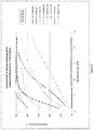
FIG. 4 is a graph showing the % recovery of C4, C5 and C6+ hydrocarbons in a HGL stream from a hydrocarbon gas stream when using the process of the present invention (Enhanced) to effectively direct all the C3 to the sales gas stream over a feed gas richness ranging from 1 to 9 GPM, (gal/mcf) in comparison to the conventional refrigeration process of the prior art.
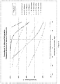
FIG. 5 is a graph showing the % recovery of C6+, C5, C4, C3, from a hydrocarbon gas stream having a richness of 5 GPM at a constant cold separator pressure of 600 Psig, and at various cold separator temperatures ranging between −40° F. and 20° F., using the process of the present invention (Enhanced) when directing effectively all the C3 to the sales gas stream, in comparison to the conventional refrigeration process of the prior art.
FIG. 6 is a graph showing the % recovery of C5, and C4, from a hydrocarbon gas stream having a richness of 5 GPM at a constant cold separator temperature of 13° F., and at various cold separator pressures between 200 Psig and 1200 Psig, using the process of the present invention (Enhanced) when directing effectively all the C3 to the sales gas stream, in comparison to the conventional refrigeration process of the prior art.
FIG. 7 is a graph showing the C4 recovery versus refrigeration power for a hydrocarbon gas stream having a richness of 5 GPM using the process of the present invention (Enhanced) in comparison to the conventional refrigeration process of the prior art.
DESCRIPTION OF THE PREFERRED EMBODIMENT
The detailed description set forth below in connection with the appended drawings is intended as a description of various embodiments of the present invention and is not intended to represent the only embodiments contemplated by the inventor. The detailed description includes specific details for the purpose of providing a comprehensive understanding of the present invention. However, it will be apparent to those skilled in the art that the present invention may be practiced without these specific details.
The purpose of gas processing such as natural gas processing is to convert raw natural gas into sales gas and HGL which can be delivered to end user markets, In other words, gas processing conditions gas to commercial specifications, e.g., hydrocarbon dew point (HCDP), water content, heating value, and other qualities as specified by a particular gas transmission or distribution company. Further, gas processing allows for the recovery of higher value liquefied products such as C2, C3, C4, and C5+ hydrocarbons, processed by one or more fractionation steps to meet commercial specifications such as hydrocarbon component content, vapor pressure, and density. As used herein “rich gas” means a gas which contains heavier hydrocarbons and is typically between temperatures of 30° F. and 120° F., and is typically provided at pressures between 200 Psig and 1000 Psig.
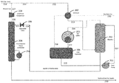
FIG. 2 shows one embodiment of a hydrocarbon gas processing plant of the present invention. In particular, rich gas feed 210 is combined with recycle gas (stream 227) to produce stream 211, which stream 211 can be further processed in at least one heat exchanger. In the embodiment shown in FIG. 2, stream 211 is only fed to a single heat exchanger as stream 212. Stream 212 is fed into a gas/gas heat exchanger 202 and is cooled in heat exchanger 202 by heat exchange with cool stream 218. It is understood, however, that stream 212 can be cooled in one or more of any cooling device, for example, such as a cooling tower, evaporative cooler, water chiller, gas chiller, waste heat exchanger, Joule-Thompson expansion valve, and the like.
However, unlike in the conventional refrigeration process shown in FIG. 1 (Prior Art), cooled gas stream 213 is directed to the bottom of heavy ends absorber tower 250, where the heavy ends are scrubbed out. Thus, in this embodiment, the flow of cooled gas stream 213 does not go to gas chiller 203 (as is the case in the conventional refrigeration process) and, instead, is directed to absorber 250. The absorber may be filled with suitable packing or trays. In absorber 250, the heavy ends are scrubbed out and are removed from the bottom of absorber 250 as liquids 224. The remaining scrubbed gas stream 216 is removed from the top of the absorber 250 and directed into gas chiller 203 for further cooling. It is understood, however, that stream 216 can be cooled in one or more of any cooling device, for example, such as a Joule-Thompson expansion valve, gas chiller, waste heat/cold exchanger, and the like. Gas chiller 203 commonly uses propane as the refrigerant but other refrigerants known in the art can also be used. Temperatures in the chiller typically range between −40° F. and 25° F.
The cold gas 217 is then fed to a cold gas separator 205, where the condensed liquids 222 are separated from the gas stream. The dry residue gas stream 218 that is produced in cold gas separator 205 is directed to gas/gas heat exchanger 202 and is used to cool gas stream 212. It is understood that heat exchanger 202 aids in reducing the energy requirement in gas chiller 203, and elevates the temperature of the sales gas stream 220 for further processing or transmission. The warmed sales gas 220 is dry relative to the rich gas feed stream 210, and is often intended to be conveyed to the gas transmission pipeline for sale (dry sales gas 220). It is understood, however, that warming the sales gas stream may not be necessary if the sales gas stream is intended to go to further cryogenic processing, for example, ethane production or liquefied natural gas (LNG) production.
Condensed liquids 222 produced in cold separator 205 are then pumped via feed pump 251 and returned to the top of absorber 250 as liquid stream 223. The counter-current flow of cooled gas stream 213 and liquid stream 223 allow the two streams to contact one another in the absorber 250 and, thus, provides multiple stages of contact to alter the composition of both the gas stream produced (gas stream 216) and the liquid stream 224. In particular, liquid stream 224 will contain fewer light hydrocarbons (e.g., C1 and C2 hydrocarbons) than in stream 223 and additional heavy hydrocarbons (e.g., C5+ hydrocarbons), which have been removed (scrubbed) from the cooled gas stream 213. Hence, the heavy hydrocarbons are scrubbed from the cooled gas stream 213 and the light hydrocarbons are stripped from light liquid stream 223. Thus, the absorber 250, gas chiller 203 and cold separator 205, in combination, operate as a rectifier column, reducing the light end components and increasing the heavier components in the absorber 250 bottom liquid product stream 224, thereby providing sharp separation between light key components and heavy key components.
The liquid stream 224 is removed from the bottom of absorber 250 and flash expanded through expansion (adjustable) valve 206 to the operating pressure of fractionation tower 208. During expansion a portion of the stream is vaporized, resulting in cooling of the total stream. The expanded stream 225 leaving expansion valve 206 is sent to fractionating tower 208 to distill the light ends (e.g. methane, ethane and propane) from the liquid, resulting in heavy liquid product 230 and light ends gaseous stream 226. The fractionation tower 208 comprises a reboiler 256, which provides heat and generates vapors to drive the distillation or fractionation process. The fractionation tower pressure typically ranges between 80 Psig to 350 Psig and reboiler temperatures range may from 140° F. to 320° F. The fractionation tower provides the versatility and ability to reject the desired proportion of mid-components from the heavy liquid product stream 225, back into the raw gas as the overhead gas stream 226. The selected operating pressure and temperature is dependent in part on what portions of mid-components are to be rejected, and the composition of the heavy liquid stream. In one embodiment, the fractionation tower 208 may further comprises a reflux condenser (not shown) to improve separation of the mid-components from the heavier ends liquid stream.
The overhead gas stream 226 from the fractionation tower 208 is then compressed in overhead compressor 209 to produce recycle gas 227. Recycle gas 227 is recycled by combining with the rich gas feed 210 and reprocessed. The bottom heavy liquids product 230 contains the HGL extracted from the gas stream.
In comparison to the conventional refrigeration process shown in FIG. 1, the HGL 230 produced by the process shown in FIG. 2 of the present invention significantly increases the volume of C5 recovered from rich gas streams having greater than 2 GPM, and significantly improves the propane rejection to the residue stream (sales gas). For example, with certain rich gas streams, i-pentane recovery in the HGL may be increased from 84.74% to 99.52%. Further, C3 rejection from HGL 230 may increase from 76.60% to 97.22%. Consequently, the dry sales gas 220 can be tailored to contain more propane and butane, thereby maximizing value from the raw gas stream for specific economic conditions.
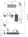
In one embodiment, the conventional refrigeration process equipment shown in FIG. 1 can be retrofitted with an absorber to achieve similar benefits as realized when practicing the process shown in FIG. 2 and described above. With reference now to FIG. 3, in this embodiment, rich gas feed (stream 310) is combined with recycle gas (stream 327) to produce stream 311. Stream 311 is then separated into two steams, stream 312 and stream 314, where stream 314 enters a gas-to-liquid heat exchanger 301 and stream 312 enters a gas-to-gas heat exchanger 302. The heat exchangers reduce the temperature of the gas streams 312 and 314, which streams exit as cooled gas stream 315 and cooled gas stream 313, respectively. Streams 313 and 315 are then combined and, when block valve 352 is in the closed position, the combined cool gas stream (stream 331) is directed to the bottom of heavy ends absorber tower 350, where the heavy ends are scrubbed out. The flow of both cooled gas stream 313 and cooled gas stream 315 is controlled by block valve 352. In absorber 350, the heavy ends are scrubbed out and are removed from the bottom of absorber 350 as liquids 332. The remaining scrubbed gas stream 316 is removed from the top of the absorber 350 and directed into gas chiller 303 for further cooling. It is understood, however, that stream 316 can be cooled in one or more of any cooling device, for example, such as a Joule-Thompson expansion valve, gas chiller, waste heat/cold exchanger, and the like. Gas chiller 303 commonly uses propane as the refrigerant but other refrigerants known in the art can also be used. Temperatures in the chiller typically range between −40° F. and 25° F.
The cold gas 317 is then fed to a cold gas separator 305, where the condensed liquids 322 are separated from the gas stream. The dry residue gas stream 318 that is produced in cold gas separator 305 is directed to gas/gas heat exchanger 302 and is used to cool gas stream 312. It is understood that heat exchangers 301 and 302 aid in reducing the energy requirement in gas chiller 303, and elevate the temperature of the sales gas stream 320 for further processing or transmission. The warmed sales gas 320 is dry relative to the rich gas feed stream 310, and is often intended to be conveyed to the gas transmission pipeline for sale (dry sales gas 320). It is understood, however, that warming the sales gas stream may not be necessary if the sales gas stream is intended to go to further cryogenic processing, for example, ethane production or liquefied natural gas (LNG) production.
When block valve 353 is in the closed position, condensed liquids 322 produced in cold separator 305 are pumped via feed pump 351 and returned to the top of absorber 350 as liquid stream 323. The counter-current flow of combined cool gas stream 331 and liquid stream 323 allow the two streams to contact one another in the absorber 350 and, thus, provides multiple stages of contact to alter the composition of both the gas stream produced (gas stream 316) and the liquid stream 332. In particular, liquid stream 332 will contain fewer light hydrocarbons (e.g., C1 and C2 hydrocarbons) than in stream 323 and more heavy hydrocarbons (e.g., C5+ hydrocarbons), which have been removed (scrubbed) from the combined cool gas stream 331. Hence, the heavy hydrocarbons are scrubbed from the combined cool gas stream 331 and the light hydrocarbons are stripped from the liquid. Thus, in this embodiment, the absorber 350, gas chiller 303 and cold separator 305, in combination, also operate as a rectifier column, reducing the light end components and increasing the heavier components in the absorber 350 bottom liquid product stream 332, thereby providing sharp separation between light key components and heavy key components.
The liquid stream 332 is removed from the bottom of absorber 350 and passes into Gas/Liquid heat exchanger 301, being warmed by the raw gas stream 314. Stream 324 exits Gas/Liquid heat exchanger 301 and is flash expanded through expansion (adjustable) valve 306 to the operating pressure of fractionation tower 308. During expansion a portion of the stream is vaporized, resulting in cooling of the total stream. The expanded stream 325 leaving expansion valve 306 is sent to fractionating tower 308 to distill the light ends (e.g. methane, ethane and propane) from the liquid, resulting in heavy liquid product 330 and light ends gaseous stream 326. The fractionation tower 308 comprises a reboiler 356, which provides heat and generates vapors to drive the distillation or fractionation process. In one embodiment, the fractionation tower 308 may further comprises a reflux condenser (not shown) to improve separation of the light ends (e.g. methane, ethane and propane) from the heavier ends liquid stream.
The overhead gas stream 326 from the fractionation tower 308 is then compressed in overhead compressor 309 to produce recycle gas 327. Recycle gas 327 is recycled by combining with the rich gas feed 310 and reprocessed. The bottom heavy liquids product 330 contains the HGL extracted from the gas stream.
Thus, in the embodiment shown in FIG. 3, the hydrocarbon gas processing plant can operate either as a conventional refrigeration processing plant or as a hydrocarbon gas processing plant of the present invention. When blocking valves 352, 353 are in the closed position, the plant operates as a hydrocarbon gas processing plant of the present invention. However, when block valves 352, 353 are in the open position, the plant will operate as a conventional refrigeration processing plant. The present invention is adaptable to existing gas processing plants already employing the prior art, or a version thereof.
EXAMPLE 1
A comparison of the composition of the sales gas produced from the conventional refrigeration process (FIG. 1 (Prior Art)) and the sales gas of the present invention (FIG. 2) when targeting a sales gas hydrocarbon dew point (HCDP) of 23° F. at 800 Psig is shown in Table 1 below.
TABLE 1
Conventional Enhanced
Component - mol fraction Rich Gas Feed Sales Gas Sales Gas
Helium 0.000993 0.001043 0.001029
Nitrogen 0.008428 0.008856 0.008737
CO2 0.007692 0.008044 0.007973
H2S 0.000002 0.000002 0.000002
Methane 0.721123 0.757708 0.747454
Ethane 0.144403 0.151728 0.149624
Propane 0.073780 0.059381 0.073939
i-Butane 0.011130 0.004904 0.005582
n-Butane 0.021026 0.007102 0.005637
i-Pentane 0.004011 0.000643 0.000021
n-Pentane 0.003884 0.000476 0.000004
Hexane 0.001685 0.000072 0.000000
Heptane 0.001176 0.000034 0.000000
Octane 0.000574 0.000008 0.000000
Nonane 0.000078 0.000000 0.000000
Decane+ 0.000014 0.000000 0.000000
1.000000 1.000000 1.000000
It can be seen from Table 1 that when using the present invention (Enhanced), much more propane and i-butane report to the sales gas and much less C5+ hydrocarbons (i.e., i-pentane, n-pentane, n-hexane, n-heptane, n-octane, n-nonane and n-decane) are present therein when compared to the sales gas of the Prior Art (Conventional). Further, essentially no heavy hydrocarbons (C5+ components) were found in the sales gas. Hence, the enhancement of the present invention results in high recovery (removal) of heavy hydrocarbons (C5+ components) from the rich gas feed and more rejection of lighter hydrocarbons such as C3 and i-C4 to the sales gas product. Yet, both conventional and enhanced sales gas streams achieve the same HCDP.
Thus, under prescribed conditions, the present invention (Enhanced) produces a more valuable HGL stream per unit of volume than when using the Prior Art conventional refrigeration process. This can be seen more clearly in Table 2.
TABLE 2
Process
Parameter Units Conventional Enhanced
Rich Gas Feed Rate MMscfd 26.3 26.3
Sales Gas HCDP ° F. at Target 23° Target 23°
800 Psig
Cold Sep. Temperature ° F. −4.0 11.1
Cold Sep. Pressure Psig 490 480
Chiller duty MMbtu/hr 3.09 2.46
Refridge Compressor HP 788 569 −27.8%
Load
HC liq to Fractionator bbl/day 2140 1874
Fractionator Pressure Psig 270 270
Fractionator Ovhd. Vol. MMscfd 2.49 1.93
Overhead Compressor HP 84 65 −22.6%
Load
Fractionator Reboiler ° F. 204 252
Temperature
Fractionator Reboiler MMbtu/hr 1.89 2.04 7.9%
Duty
HGL Product Volume bbl/day 942 729
Sales Gas Volume MMscfd 25.02 25.37 1.4%
Higher Heating Value btu/scf 1219 1234 1.2%
Propane Recovery % of Feed 23.40 2.78
i-Butane Recovery % of Feed 58.07 51.68
n-Butane Recovery % of Feed 67.85 74.55
i-Pentane Recovery % of Feed 84.74 99.52
n-Pentane Recovery % of Feed 88.33 99.91
Hexane Recovery % of Feed 95.93 100.00
Heptane Recovery % of Feed 98.55 100.00
Propane Yield bbl/day 293.3 38.7
Butanes Yield bbl/day 408.4 422.4
C5+ Yield bbl/day 240.7 267.8
HGL-Product:Feed Ratio bbl/ 37.68 29.14
MMscf
In particular, when targeting a sales gas HCDP of 23° F. at 800 Psig, it can be seen from Table 2 that the HGL stream produced using the Conventional process yields 293.3 bbl/d propane, 408.4 bbl/d of butanes and 240.7 bbl/d of pentanes+ (C5+). On the other hand, when using the Enhanced process of the present invention, only 38.7 bbl/d of propane are yielded in the HGL stream. This results in a marginally higher sales gas volume with slightly higher heating value due to more propane (C3) being directed to the sales gas stream, which may be favorable for specific economic conditions. Further, 267.8 bbl/d of pentanes+ (C5+) are yielded in the HGL stream (as compared to 240.7 bbl/d in Conventional), resulting in better recovery of heavy hydrocarbons in the HGL product.
Furthermore, Table 2 shows that when using the Enhanced process of the present invention the refrigeration compressor load decreases 27.8%, and the overhead compressor load decreases 22.6%, resulting in significantly lower utility requirements and slightly smaller equipment having lower capital costs, when comparing to the conventional refrigeration process (Prior Art). Further, the cold separator can be operated at a much higher temperature, i.e., 11.1° F. versus −4.0° F. with the conventional refrigeration process.
Table 3 below further illustrates the difference in intermediate liquid streams compositions generated in the conventional refrigeration of the prior art as compared to the present invention (Enhanced). Specifically, in the present invention, stream 222, which is the liquid stream produced in the cold separator 205, contains much less C5+ (heavy ends) as compared to stream 122 in the conventional refrigeration process. This is because the C5+ (heavy ends) have already been stripped out of the raw gas in the absorber 250, and, thus, a much lighter liquid product is produced in cold separator 205 to send to the absorber 250 as a scrubbing fluid.
Thus, liquid streams 224, 225, which are produced in the absorber 250 and fed to the fractionation tower 208, respectively, will contain higher volume flows of C4 (and C5+ heavier components) and much less C3 and lighter components when compared to liquid streams 122, 124 and 125 of the conventional art, which streams are produced in the cold separator 105, cooled in gas/liquid exchanger 101, and fed into fractionation tower 108, respectively.
TABLE 3
Stream
122 & 125
Conventional Stream 222
Cold Sep. Enhanced Stream 225
Component - Liquid & Liq. Cold Sep. Enhanced
bbl/d To Frac. Liquid Liq. To Frac.
Helium 0 0 0
Nitrogen 1 1 1
CO2 9 6 4
H2S 0 0 0
Methane 358 234 190
Ethane 555 396 286
Propane 670 693 531
i-Butane 168 147 177
n-Butane 333 198 410
i-Pentane 84 2 103
n-Pentane 82 0 97
Hexane 42 0 45
Heptane 29 0 30
Octane 7 0 7
Nonane 11 0 11
Decane + 1 0 1
2349 1678 1892
EXAMPLE 2
Table 4 below shows the flexibility of the present invention using the same rich gas feed as in Example 1. In this example, the objective is to obtain the maximum liquids possible, including propane and butanes, while the refrigeration compressor load is limited to 1151 HP for both the Conventional and Enhanced process.
TABLE 4
Component - Rich Gas Conventional Enhanced
mol fraction Feed Sales Gas Sales Gas
Helium 0.000993 0.001081 0.001085
Nitrogen 0.008428 0.009176 0.009212
CO2 0.007692 0.008321 0.008407
H2S 0.000002 0.000002 0.000002
Methane 0.721123 0.784952 0.788098
Ethane 0.144403 0.156153 0.156904
Propane 0.073780 0.034538 0.036099
i-Butane 0.011130 0.002296 0.000159
n-Butane 0.021026 0.003042 0.000034
i-Pentane 0.004011 0.000237 0.000000
n-Pentane 0.003884 0.000166 0.000000
Hexane 0.001685 0.000022 0.000000
Heptane 0.001176 0.000010 0.000000
Octane 0.000574 0.000002 0.000000
Nonane 0.000078 0.000000 0.000000
Decane + 0.000014 0.000000 0.000000
1.000000 1.000000 1.000000
Process
Con-
Parameter Units ventional Enhanced
Rich Gas Feed Rate MMscfd 26.3 26.3
Sales Gas HCDP ° F. at −5.8 −18.0
800 Psig
Cold Sep. Temperature ° F. −13.0 −29.2
Cold Sep. Pressure Psig 490 480
Chiller duty MMbtu/hr 4.35 3.61
Refridge Compressor Load HP 1151 1154 0.3%
HC liq to Fractionator bbl/day 8416 2679
Fractionator Pressure Psig 300 300
Fractionator Ovhd. Vol. MMscfd 4.28 2.11
Overhead Compressor Load HP 144 63 −56.3%
Frationator Reboiler Temp. ° F. 188 192
Fractionator Reboiler Duty MMbtu/hr 2.49 2.27 −8.8%
HGL Product Volume bbl/day 1521 1599
Sales Gas Volume MMscfd 24.14 24.05 −0.4%
Higher Heating Value btu/scf 1167 1157 −0.9%
Propane Recovery % of Feed 57.00 55.23
i-Butane Recovery % of reed 81.05 98.69
n-Butane Recovery % of Feed 86.71 99.85
i-Pentane Recovery % of Feed 94.56 100.00
n-Pentane Recovery % of Feed 96.07 100.00
Hexane Recovery % of Feed 98.80 100.00
Heptane Recovery % of Feed 99.61 100.00
Propane Yield bbl/day 713.0 690.4
Butanes Yield bbl/day 536.6 628.6
C5+ Yield bbl/day 257.8 266.9
1,507 1,586 5.2%
HGL-Product:Feed Ratio bbl/ 60.82 63.93 5.1%
MMscf

Under the prescribed conditions, the present invention (Enhanced) is capable of achieving a lower Cold Separator temperature and consequently recovering higher amounts of HGL than when using the conventional refrigeration process (Conventional). Once again, the sales gas composition of the Enhanced process contains a lesser amount of butanes (C4) and pentanes+ (C5+) than does the Conventional process. As well, the utility requirements for the Overhead compressor load and Fractionation Reboiler Duty are significantly less.
EXAMPLES 3 and 4
Table 5 further shows the flexibility of the Enhanced process of the present invention using the same rich gas feed as in Example 1 and Example 2 above. Example 3 reflects the ability to reject propane into the sales gas stream, yet with high butane recovery in the HGL stream. Example 4 reflects the ability to direct both propane and butane into the sales gas stream to produce a de-butanized condensate (C5+) product stream.
TABLE 5
Example 3 Example 4
Enhanced Enhanced
Propane Butane
Component - Rich Gas Rejection Rejection
mol fraction Feed Sales Gas Sales Gas
Helium 0.000993 0.001038 0.001005
Nitrogen 0.008428 0.008817 0.008537
CO2 0.007692 0.008043 0.007789
H2S 0.000002 0.000002 0.000002
Methane 0.721123 0.754234 0.730304
Ethane 0.144403 0.150850 0.146128
Propane 0.073780 0.074884 0.074431
i-Butane 0.011130 0.001593 0.011147
n-Butane 0.021026 0.000538 0.020250
i-Pentane 0.004011 0.000001 0.000324
n-Pentane 0.003884 0.000000 0.000084
Hexane 0.001685 0.000000 0.000000
Heptane 0.001176 0.000000 0.000000
Octane 0.000574 0.000000 0.000000
Nonane 0.000078 0.000000 0.000000
Decane + 0.000014 0.000000 0.000000
1.000000 1.000000 1.000000
Process
Parameter Units
Rich Gas Feed Rate MMscfd 26.3 26.3
Sales Gas HCDP ° F. at 800 Psig 10.4 48.0
Cold Sep. Temperature ° F. −2.2 36.0
Cold Sep. Pressure Psig 480 480
Chiller duty MMbtu/hr 3.46 2.12
Refridge Compressor Load HP 864 449
HC liq to Fractionator bbl/day 3234 2233
Fractionator Pressure Psig 270 100
Fractionator Ovhd. Vol. MMscfd 3.89 2.94
Overhead Compressor Load HP 128 262
Fractinoator Reboiler Temp. ° F. 248 248
Fractionator Reboiler Duty MMbtu/hr 3.51 2.55
HGL Product Volume bbl/day 895 274
Sales Gas Volume MMscfd 25.13 25.95
Higher Heating Value btu/scf 1216 1279
Propane Recovery % of Feed 2.99 0.41
i-Butane Recovery % of Feed 86.32 1.15
n-Butane Recovery % of Feed 97.56 4.94
i-Pentane Recovery % of Feed 99.99 92.02
n-Pentane Recovery % of Feed 100.00 97.86
Hexane Recovery % of Feed 100.00 100.00
Heptane Recovery % of Feed 100.00 100.00
Propane Yield bbl/day 29.8 0.0
Butanes Yield bbl/day 596.6 13.2
C5+ Yield bbl/day 268.3 261.2
895 274
HGL-Product:Feed Ratio bbl/MMscf 35.77 10.97

In Example 3, the results show a sharp separation between C3 (propane) recovery at 2.99% and i-C4 (i-butane) recovery at 86.32%. Example 4, under different operating conditions, shows a sharp distinction between n-C4 (n-butane) recovery of 4.94%, and iC5 (i-pentane) recovery of 92.02%.
Examples 1 to 4 demonstrate the flexibility of the present invention and enable one to respond to market conditions to maximize the profitability from a raw gas stream.
EXAMPLE 5
In Example 5, the process of the present invention is used (Enhanced refrigeration) to recover sales gas and HGL product. The cold separator is operated at −13° F. and 600 Psig and various gas feeds of varying richness were contemplated. The relative richness or amount of the heavier gaseous hydrocarbons, can be expressed in terms of gallons per mcf (thousand cubic feet), abbreviated as GPM. In this embodiment, GPM includes all hydrocarbon components heavier than methane and represents the total volume, in liquid gallons, contained in one thousand cubic feet of a particular gas at standard conditions.
Recovery of C6+ (heavy hydrocarbons), C5 (pentane) and C4 (butane) in the HGL product were determined and the results are shown in FIG. 4. It can be seen from the graph in FIG. 4 that, in both the present invention (Enhanced) and the conventional process (Conventional), the component recoveries gradually increase with increasing gas richness. However, component recoveries in the present invention (Enhanced) exceed the component recoveries in the conventional process (Conventional) when using raw gas feed streams having richness of about 2 GPM and higher. It can be seen that for 4 GPM gas, very high recoveries, approaching 100% of C5 and C6+, can be recovered in the HGL stream (i.e., removed from the raw gas feed stream).
Also significant is the fact that, when using the present invention (Enhanced) with any of the raw gas feed richness examined, essentially no propane is recovered in the HGL product. Thus, when using the present invention (Enhanced), essentially the total amount of propane can report to the sales gas stream under selected conditions. However, as demonstrated in Example 2, a significant amount of propane recovery is possible.
EXAMPLE 6
In Example 6, the cold separator was operated at 600 Psig and various operating temperatures of the cold separator were contemplated using a raw gas feed stream having a richness of 5 GPM employing both the conventional prior art process (Conventional) and the process of the present invention (Enhanced). The graph in FIG. 5 shows that the cold separator can be operated at much higher temperatures in the present invention (Enhanced) for recovery of 100% of the C5 and C6+ hydrocarbons (in the HGL product) than when using the conventional refrigeration process (Conventional). In particular, at about −13° F., 100% of C5 was recovered in the present invention (Enhanced) whereas only about 92% of the C5 was recovered using conventional refrigeration process (Conventional). In fact, even at −25° F., only about 95% of the C5 was recovered in the conventional refrigeration process (Conventional). Also at the −25° F. cold separator temperature, the present invention (Enhanced) is capable of recovering 100% of the butane, whereas about only 80% of the C4 will also be removed by the conventional refrigeration process (Prior Art).
FIG. 5 also shows that, when it is desirable for butane to report to the sales gas stream and be rejected from the HGL stream, 97.4% C5 recovery can be achieved at only 14° F. cold separator temperature. Further, it can be seen that for all temperature ranges, very little C3 (propane) can be directed to the HGL product when using the present invention (Enhanced).
EXAMPLE 7
In Example 7, the cold separator was operated at −13° F. and various operating pressures between 200 and 1200 Psig of the cold separator were contemplated, using a raw gas feed stream having a richness of 5 GPM. In this example, it was desirable to have all of the C3 report to the sales gas stream and the majority of the C4 and C5 report to the HGL stream. Both the conventional prior art process (Conventional) and the process of the present invention (Enhanced) were investigated. The graph in FIG. 6 shows that the cold separator can be operated at a much broader range of pressures in the present invention (Enhanced) for recovery of 100% of the C5 and C6+ hydrocarbons (in the HGL product) than when using the conventional refrigeration process (Conventional). In particular, between 400 Psig and 1000 Psig, 100% of C5 was recovered in the present invention (Enhanced) whereas only between 80% and 92% of the C5 was recovered using the conventional refrigeration process (Prior Art).
FIG. 6 also shows that, when the pressure exceeds 500 Psig, that butane recovery in the Present Invention exceeds that of the conventional refrigeration process (Prior Art). In fact, the maximum butane recovery for the Present Invention (Enhanced) is about 84% and occurs at about 800 Psig, as compared to the Prior Art (Conventional) butane recovery at about 69%.
The present invention provides the potential to produce a sales gas stream meeting pipeline specifications at a higher pressure when compared to the Prior Art (Conventional). This may be an advantage when the gas transmission pipeline operates at pressures between 900 and 1200 Psig.
EXAMPLE 8
In Example 8, a gas feed stream having a richness of 5 GPM was used. The cold separator was operated at 600 Psi and various operating temperatures of the cold separator were tested using both the conventional prior art process (Conventional) and the process of the present invention (Enhanced). The butane recovery (%) versus refrigeration load (HP/MMscf) was determined. It can be seen in graph shown in FIG. 7 that when using and operating the cold separator over a range of temperatures, the refrigeration load for the present invention (Enhanced) becomes less than the refrigeration load for the conventional refrigeration process (Conventional) for equivalent butane recoveries (in the sales gas) greater than about 62%. In particular, at a target of 80% butane recovery in the sales gas, the refrigeration load for the process of the present invention (Enhanced) was only about 23 HP/MMscf of raw gas feed, as compared to about 32 HP/MMscf when using conventional refrigeration process (Conventional).
The scope of the claims should not be limited by the preferred embodiments set forth in the examples, but should be given the broadest interpretation consistent with the description as a whole.

Claims (19)

I claim:
1. A process for separating a mixed or raw gas feed including natural gas, refinery gas, and synthetic gas, the gas feed containing methane, C2 components, C3 components, C4 components and Cs+ components into a dry gas product containing methane and C2 and a portion of C3 components or C3 and C4 components selected by a user of the process, comprising:
(a) scrubbing heavier hydrocarbon components from the gas feed to produce a scrubbed gas stream having reduced C5+ components and a first liquid stream;
(b) cooling the scrubbed gas stream and separating the cooled scrubbed gas stream into a second liquid stream containing a majority of C3 components and the dry gas product containing the selected portion of C3 components or C3 and C4 components;
(c) using the second liquid stream containing a majority of C3 components to scrub the C5+ components from the gas feed in step (a);
(d) distilling and/or fractionating the first liquid stream to form a hydrocarbon gas liquid product comprising the majority of C5+ components and an overhead gas stream comprising C3 components or C3 and C4 components; and
(e) combining the overhead gas stream with the gas feed to produce the dry gas product containing the selected portion of C3 components or C3 and C4 components.
2. The process as claimed in claim 1, further comprising cooling the gas feed prior to step (a) to reduce energy required in step (b).
3. The process as claimed in claim 1, wherein prior to combining the overhead gas stream with the gas feed the overhead gas stream is compressed.
4. The process as claimed in claim 1, wherein the hydrocarbon gas liquid product comprises the majority of the C5+components present in the gas feed.
5. The process as claimed in claim 1, wherein the hydrocarbon gas liquid product comprises greater than 95% of the C5+components present in the gas feed.
6. The process as claimed in claim 1, wherein the hydrocarbon gas liquid product comprises greater than 99% of the C5+components present in the gas feed.
7. The process as claimed in claim 1, wherein when the gas feed has an amount of hydrocarbon components heavier than methane of greater than 2GPM, the hydrocarbon gas liquid product approaching 100% of C5+and C6+hydrocarbon components present in the mixed or raw gas stream.
8. The process as claimed in claim 6, wherein when the raw gas feed has an amount of hydrocarbon components heavier than methane of between 2 GPM and 9 GPM, the raw gas feed pressure ranges between 200 and 1050 Psig, and the scrubbed gas stream is cooled and separated at a temperature between −40° F. and +25° F., the hydrocarbon gas liquid product comprises all the C5+components.
9. The process as claimed in claim 1, wherein the first liquid stream is fractionated in a fractionation tower operated at a range between 80 Psig to 350 Psig to produce the overhead gas stream and the hydrocarbon gas liquid product.
10. The process as claimed in claim 1, wherein the first liquid stream is flash distilled in a flash separator prior to step (d).
11. The process as claimed in claim 8, wherein the fractionation tower further comprises a reboiler and the reboiler temperature is selected in a range from 140° F. to 320° F., to reject the specified portion of C3 and C4 components from the first liquid stream to the overhead gas stream.
12. The process as claimed in claim 10, wherein the fractionation tower further comprises a reflux condenser for further separation of C3 and/or C4 components from the first liquid stream.
13. The process as claimed in claim 11, wherein prior to combining the overhead gas stream with the gas feed the overhead gas stream is compressed.
14. The process as claimed 12, wherein the operating pressure and temperature of the fractionation tower is dependent on what portion of the C3and C4 components are to be directed to the overhead gas stream.
15. The process as claimed in claim 2, wherein the gas feed is cooled in at least one heat exchanger.
16. The process as claimed in claim 1, wherein the scrubbing step (a) occurs in an absorber.
17. The process as claimed in claim 1, wherein the scrubbed gas stream is cooled in a cooling device selected from the group consisting of a Joule-Thompson expansion valve, gas chiller and waste heat/cold exchanger.
18. The process as claimed in claim 17, wherein the cooled scrubbed gas stream is separated into the second liquid stream and the dry gas product in a separator.
19. The process as claimed in claim 1, wherein step (d) occurs in a flash separator.
US15/353,603 2016-01-22 2016-11-16 Process and apparatus for processing a hydrocarbon gas stream Expired - Fee Related US10520249B2 (en)

Priority Applications (1)

Application Number Priority Date Filing Date Title
US15/353,603 US10520249B2 (en) 2016-01-22 2016-11-16 Process and apparatus for processing a hydrocarbon gas stream

Applications Claiming Priority (2)

Application Number Priority Date Filing Date Title
US201662286132P 2016-01-22 2016-01-22
US15/353,603 US10520249B2 (en) 2016-01-22 2016-11-16 Process and apparatus for processing a hydrocarbon gas stream

Publications (2)

Publication Number Publication Date
US20170211877A1 US20170211877A1 (en) 2017-07-27
US10520249B2 true US10520249B2 (en) 2019-12-31

Family

ID=58794307

Family Applications (1)

Application Number Title Priority Date Filing Date
US15/353,603 Expired - Fee Related US10520249B2 (en) 2016-01-22 2016-11-16 Process and apparatus for processing a hydrocarbon gas stream

Country Status (2)

Country Link
US (1) US10520249B2 (en)
CA (1) CA2949012C (en)

Cited By (2)

* Cited by examiner, † Cited by third party
Publication number Priority date Publication date Assignee Title
US20220306553A1 (en) * 2021-03-25 2022-09-29 Exterran Corporation System, apparatus, and method for hydrocarbon processing
US12313338B2 (en) 2021-05-14 2025-05-27 Chart Energy & Chemicals, Inc. Side draw reflux heavy hydrocarbon removal system and method

Families Citing this family (1)

* Cited by examiner, † Cited by third party
Publication number Priority date Publication date Assignee Title
US10894929B1 (en) 2019-10-02 2021-01-19 Saudi Arabian Oil Company Natural gas liquids recovery process

Citations (22)

* Cited by examiner, † Cited by third party
Publication number Priority date Publication date Assignee Title
US4115086A (en) 1975-12-22 1978-09-19 Fluor Corporation Recovery of light hydrocarbons from refinery gas
US4511381A (en) 1982-05-03 1985-04-16 El Paso Hydrocarbons Company Process for extracting natural gas liquids from natural gas streams with physical solvents
US4653698A (en) 1983-08-01 1987-03-31 The Babcock & Wilcox Company Safety system for coal pulverizers
US4673488A (en) 1985-08-26 1987-06-16 Uop Inc. Hydrocarbon-conversion process with fractionator overhead vapor recycle
US5462583A (en) 1994-03-04 1995-10-31 Advanced Extraction Technologies, Inc. Absorption process without external solvent
US5546764A (en) 1995-03-03 1996-08-20 Advanced Extraction Technologies, Inc. Absorption process for recovering ethylene and hydrogen from refinery and petrochemical plant off-gases
US6453698B2 (en) 2000-04-13 2002-09-24 Ipsi Llc Flexible reflux process for high NGL recovery
US6658893B1 (en) 2002-05-30 2003-12-09 Propak Systems Ltd. System and method for liquefied petroleum gas recovery
US6662589B1 (en) * 2003-04-16 2003-12-16 Air Products And Chemicals, Inc. Integrated high pressure NGL recovery in the production of liquefied natural gas
US6712880B2 (en) 2001-03-01 2004-03-30 Abb Lummus Global, Inc. Cryogenic process utilizing high pressure absorber column
US20040148964A1 (en) 2002-12-19 2004-08-05 Abb Lummus Global Inc. Lean reflux-high hydrocarbon recovery process
WO2004069384A1 (en) 2003-02-10 2004-08-19 Shell Internationale Research Maatschappij B.V. Removing natural gas liquids from a gaseous natural gas stream
US20050229634A1 (en) 2004-04-15 2005-10-20 Abb Lummus Global Inc. Hydrocarbon gas processing for rich gas streams
US20060005573A1 (en) * 2002-07-23 2006-01-12 Rudolf Stockmann Method for liquefying a hydrocarbon-rich flow while simultaneously obtaining a c3/c4-rich fraction
US7875759B2 (en) 2004-11-04 2011-01-25 Rafael Bin Mohd Shamsudin Process for extracting natural gas liquids from natural gas
WO2013056267A1 (en) 2011-10-12 2013-04-18 Fluor Technologies Corporation Configurations and methods of heating value control in lng liquefaction plant
US20130305777A1 (en) 2007-05-18 2013-11-21 Pilot Energy Solutions, Llc Heavy Hydrocarbon Processing in NGL Recovery System
US8794030B2 (en) 2009-05-15 2014-08-05 Ortloff Engineers, Ltd. Liquefied natural gas and hydrocarbon gas processing
US20140303416A1 (en) 2011-01-19 2014-10-09 Exxonmobil Chemical Patents Inc. Method and Apparatus for Converting Hydrocarbons Into Olefins
US20150073196A1 (en) 2013-09-11 2015-03-12 Ortloff Engineers, Ltd. Hydrocarbon Gas Processing
US20150073194A1 (en) 2013-09-11 2015-03-12 Ortloff Engineers, Ltd. Hydrocarbon Gas Processing
US20160216030A1 (en) * 2015-01-23 2016-07-28 Air Products And Chemicals, Inc. Separation of Heavy Hydrocarbons and NGLs from Natural Gas in Integration with Liquefaction of Natural Gas

Family Cites Families (1)

* Cited by examiner, † Cited by third party
Publication number Priority date Publication date Assignee Title
JP4274482B2 (en) * 2004-06-30 2009-06-10 大豊工業株式会社 Die casting equipment

Patent Citations (22)

* Cited by examiner, † Cited by third party
Publication number Priority date Publication date Assignee Title
US4115086A (en) 1975-12-22 1978-09-19 Fluor Corporation Recovery of light hydrocarbons from refinery gas
US4511381A (en) 1982-05-03 1985-04-16 El Paso Hydrocarbons Company Process for extracting natural gas liquids from natural gas streams with physical solvents
US4653698A (en) 1983-08-01 1987-03-31 The Babcock & Wilcox Company Safety system for coal pulverizers
US4673488A (en) 1985-08-26 1987-06-16 Uop Inc. Hydrocarbon-conversion process with fractionator overhead vapor recycle
US5462583A (en) 1994-03-04 1995-10-31 Advanced Extraction Technologies, Inc. Absorption process without external solvent
US5546764A (en) 1995-03-03 1996-08-20 Advanced Extraction Technologies, Inc. Absorption process for recovering ethylene and hydrogen from refinery and petrochemical plant off-gases
US6453698B2 (en) 2000-04-13 2002-09-24 Ipsi Llc Flexible reflux process for high NGL recovery
US6712880B2 (en) 2001-03-01 2004-03-30 Abb Lummus Global, Inc. Cryogenic process utilizing high pressure absorber column
US6658893B1 (en) 2002-05-30 2003-12-09 Propak Systems Ltd. System and method for liquefied petroleum gas recovery
US20060005573A1 (en) * 2002-07-23 2006-01-12 Rudolf Stockmann Method for liquefying a hydrocarbon-rich flow while simultaneously obtaining a c3/c4-rich fraction
US20040148964A1 (en) 2002-12-19 2004-08-05 Abb Lummus Global Inc. Lean reflux-high hydrocarbon recovery process
WO2004069384A1 (en) 2003-02-10 2004-08-19 Shell Internationale Research Maatschappij B.V. Removing natural gas liquids from a gaseous natural gas stream
US6662589B1 (en) * 2003-04-16 2003-12-16 Air Products And Chemicals, Inc. Integrated high pressure NGL recovery in the production of liquefied natural gas
US20050229634A1 (en) 2004-04-15 2005-10-20 Abb Lummus Global Inc. Hydrocarbon gas processing for rich gas streams
US7875759B2 (en) 2004-11-04 2011-01-25 Rafael Bin Mohd Shamsudin Process for extracting natural gas liquids from natural gas
US20130305777A1 (en) 2007-05-18 2013-11-21 Pilot Energy Solutions, Llc Heavy Hydrocarbon Processing in NGL Recovery System
US8794030B2 (en) 2009-05-15 2014-08-05 Ortloff Engineers, Ltd. Liquefied natural gas and hydrocarbon gas processing
US20140303416A1 (en) 2011-01-19 2014-10-09 Exxonmobil Chemical Patents Inc. Method and Apparatus for Converting Hydrocarbons Into Olefins
WO2013056267A1 (en) 2011-10-12 2013-04-18 Fluor Technologies Corporation Configurations and methods of heating value control in lng liquefaction plant
US20150073196A1 (en) 2013-09-11 2015-03-12 Ortloff Engineers, Ltd. Hydrocarbon Gas Processing
US20150073194A1 (en) 2013-09-11 2015-03-12 Ortloff Engineers, Ltd. Hydrocarbon Gas Processing
US20160216030A1 (en) * 2015-01-23 2016-07-28 Air Products And Chemicals, Inc. Separation of Heavy Hydrocarbons and NGLs from Natural Gas in Integration with Liquefaction of Natural Gas

Non-Patent Citations (1)

* Cited by examiner, † Cited by third party
Title
Gas Processors Suppliers Association, Hydrocarbon Recovery, Gas Processors Suppliers Association Engineering Data Book, 2012, Section 16, Gas Suppliers Association, Tulsa, Oklahoma, USA. *

Cited By (3)

* Cited by examiner, † Cited by third party
Publication number Priority date Publication date Assignee Title
US20220306553A1 (en) * 2021-03-25 2022-09-29 Exterran Corporation System, apparatus, and method for hydrocarbon processing
US11884621B2 (en) * 2021-03-25 2024-01-30 Enerflex Us Holdings Inc. System, apparatus, and method for hydrocarbon processing
US12313338B2 (en) 2021-05-14 2025-05-27 Chart Energy & Chemicals, Inc. Side draw reflux heavy hydrocarbon removal system and method

Also Published As

Publication number Publication date
CA2949012C (en) 2018-02-20
US20170211877A1 (en) 2017-07-27
CA2949012A1 (en) 2017-05-30

Similar Documents

Publication Publication Date Title
CA2176430C (en) Retrofit unit for upgrading natural gas refrigeration plants
EP2889450B1 (en) Process for recovering hydrocarbons from crude carbon dioxide fluid
US6516631B1 (en) Hydrocarbon gas processing
US9074815B2 (en) Nitrogen removal with ISO-pressure open refrigeration natural gas liquids recovery
CA2723831C (en) Iso-pressure open refrigeration ngl recovery
US11486636B2 (en) Method to recover LPG and condensates from refineries fuel gas streams
KR20190046946A (en) Pre-liquefaction pretreatment of natural gas
US9920986B2 (en) Configurations and methods for nitrogen rejection, LNG and NGL production from high nitrogen feed gases
US20180149425A1 (en) Processes for producing a natural gas stream
US10520249B2 (en) Process and apparatus for processing a hydrocarbon gas stream
US8080701B2 (en) Method and apparatus for treating a hydrocarbon stream
EP3052586B1 (en) Split feed addition to iso-pressure open refrigeration lpg recovery
US11906244B2 (en) Hydrocarbon gas processing
US11448461B2 (en) Hydrocarbon gas processing
US12344807B2 (en) Hydrocarbon gas processing
EP4015602A1 (en) Improved operation of natural gas liquids stabilizer column
AU2013204093B2 (en) Iso-pressure open refrigeration NGL recovery
CA2777416A1 (en) A method to recover lpg and condensates from refineries fuel gas streams

Legal Events

Date Code Title Description
AS Assignment

Owner name: ENCANA CORPORATION, CANADA

Free format text: ASSIGNMENT OF ASSIGNORS INTEREST;ASSIGNOR:HORNE, STEPHEN CRAIG;REEL/FRAME:041084/0163

Effective date: 20161207

STPP Information on status: patent application and granting procedure in general

Free format text: DOCKETED NEW CASE - READY FOR EXAMINATION

STPP Information on status: patent application and granting procedure in general

Free format text: NON FINAL ACTION MAILED

STPP Information on status: patent application and granting procedure in general

Free format text: RESPONSE TO NON-FINAL OFFICE ACTION ENTERED AND FORWARDED TO EXAMINER

STPP Information on status: patent application and granting procedure in general

Free format text: NOTICE OF ALLOWANCE MAILED -- APPLICATION RECEIVED IN OFFICE OF PUBLICATIONS

STPP Information on status: patent application and granting procedure in general

Free format text: PUBLICATIONS -- ISSUE FEE PAYMENT VERIFIED

STCF Information on status: patent grant

Free format text: PATENTED CASE

AS Assignment

Owner name: OVINTIV CANADA ULC, CANADA

Free format text: CHANGE OF NAME;ASSIGNOR:ENCANA CORPORATION;REEL/FRAME:052469/0514

Effective date: 20200124

FEPP Fee payment procedure

Free format text: MAINTENANCE FEE REMINDER MAILED (ORIGINAL EVENT CODE: REM.); ENTITY STATUS OF PATENT OWNER: LARGE ENTITY

LAPS Lapse for failure to pay maintenance fees

Free format text: PATENT EXPIRED FOR FAILURE TO PAY MAINTENANCE FEES (ORIGINAL EVENT CODE: EXP.); ENTITY STATUS OF PATENT OWNER: LARGE ENTITY

STCH Information on status: patent discontinuation

Free format text: PATENT EXPIRED DUE TO NONPAYMENT OF MAINTENANCE FEES UNDER 37 CFR 1.362

FP Lapsed due to failure to pay maintenance fee

Effective date: 20231231