US10514209B2 - Water-cooling type secondary battery - Google Patents
Water-cooling type secondary battery Download PDFInfo
- Publication number
- US10514209B2 US10514209B2 US14/362,171 US201214362171A US10514209B2 US 10514209 B2 US10514209 B2 US 10514209B2 US 201214362171 A US201214362171 A US 201214362171A US 10514209 B2 US10514209 B2 US 10514209B2
- Authority
- US
- United States
- Prior art keywords
- heat radiating
- radiating plate
- refrigerant pipe
- groove
- refrigerant
- Prior art date
- Legal status (The legal status is an assumption and is not a legal conclusion. Google has not performed a legal analysis and makes no representation as to the accuracy of the status listed.)
- Active, expires
Links
Images


Classifications
-
- F—MECHANICAL ENGINEERING; LIGHTING; HEATING; WEAPONS; BLASTING
- F28—HEAT EXCHANGE IN GENERAL
- F28F—DETAILS OF HEAT-EXCHANGE AND HEAT-TRANSFER APPARATUS, OF GENERAL APPLICATION
- F28F1/00—Tubular elements; Assemblies of tubular elements
-
- H—ELECTRICITY
- H01—ELECTRIC ELEMENTS
- H01M—PROCESSES OR MEANS, e.g. BATTERIES, FOR THE DIRECT CONVERSION OF CHEMICAL ENERGY INTO ELECTRICAL ENERGY
- H01M10/00—Secondary cells; Manufacture thereof
- H01M10/60—Heating or cooling; Temperature control
- H01M10/61—Types of temperature control
- H01M10/613—Cooling or keeping cold
-
- H—ELECTRICITY
- H01—ELECTRIC ELEMENTS
- H01M—PROCESSES OR MEANS, e.g. BATTERIES, FOR THE DIRECT CONVERSION OF CHEMICAL ENERGY INTO ELECTRICAL ENERGY
- H01M10/00—Secondary cells; Manufacture thereof
- H01M10/60—Heating or cooling; Temperature control
- H01M10/64—Heating or cooling; Temperature control characterised by the shape of the cells
- H01M10/647—Prismatic or flat cells, e.g. pouch cells
-
- H—ELECTRICITY
- H01—ELECTRIC ELEMENTS
- H01M—PROCESSES OR MEANS, e.g. BATTERIES, FOR THE DIRECT CONVERSION OF CHEMICAL ENERGY INTO ELECTRICAL ENERGY
- H01M10/00—Secondary cells; Manufacture thereof
- H01M10/60—Heating or cooling; Temperature control
- H01M10/65—Means for temperature control structurally associated with the cells
- H01M10/655—Solid structures for heat exchange or heat conduction
- H01M10/6554—Rods or plates
- H01M10/6555—Rods or plates arranged between the cells
-
- H—ELECTRICITY
- H01—ELECTRIC ELEMENTS
- H01M—PROCESSES OR MEANS, e.g. BATTERIES, FOR THE DIRECT CONVERSION OF CHEMICAL ENERGY INTO ELECTRICAL ENERGY
- H01M10/00—Secondary cells; Manufacture thereof
- H01M10/60—Heating or cooling; Temperature control
- H01M10/65—Means for temperature control structurally associated with the cells
- H01M10/655—Solid structures for heat exchange or heat conduction
- H01M10/6556—Solid parts with flow channel passages or pipes for heat exchange
- H01M10/6557—Solid parts with flow channel passages or pipes for heat exchange arranged between the cells
-
- H—ELECTRICITY
- H01—ELECTRIC ELEMENTS
- H01M—PROCESSES OR MEANS, e.g. BATTERIES, FOR THE DIRECT CONVERSION OF CHEMICAL ENERGY INTO ELECTRICAL ENERGY
- H01M10/00—Secondary cells; Manufacture thereof
- H01M10/60—Heating or cooling; Temperature control
- H01M10/65—Means for temperature control structurally associated with the cells
- H01M10/656—Means for temperature control structurally associated with the cells characterised by the type of heat-exchange fluid
- H01M10/6567—Liquids
-
- F—MECHANICAL ENGINEERING; LIGHTING; HEATING; WEAPONS; BLASTING
- F28—HEAT EXCHANGE IN GENERAL
- F28D—HEAT-EXCHANGE APPARATUS, NOT PROVIDED FOR IN ANOTHER SUBCLASS, IN WHICH THE HEAT-EXCHANGE MEDIA DO NOT COME INTO DIRECT CONTACT
- F28D21/00—Heat-exchange apparatus not covered by any of the groups F28D1/00 - F28D20/00
- F28D2021/0019—Other heat exchangers for particular applications; Heat exchange systems not otherwise provided for
- F28D2021/0028—Other heat exchangers for particular applications; Heat exchange systems not otherwise provided for for cooling heat generating elements, e.g. for cooling electronic components or electric devices
- F28D2021/0029—Heat sinks
-
- F—MECHANICAL ENGINEERING; LIGHTING; HEATING; WEAPONS; BLASTING
- F28—HEAT EXCHANGE IN GENERAL
- F28D—HEAT-EXCHANGE APPARATUS, NOT PROVIDED FOR IN ANOTHER SUBCLASS, IN WHICH THE HEAT-EXCHANGE MEDIA DO NOT COME INTO DIRECT CONTACT
- F28D21/00—Heat-exchange apparatus not covered by any of the groups F28D1/00 - F28D20/00
- F28D2021/0019—Other heat exchangers for particular applications; Heat exchange systems not otherwise provided for
- F28D2021/0043—Other heat exchangers for particular applications; Heat exchange systems not otherwise provided for for fuel cells
-
- H—ELECTRICITY
- H01—ELECTRIC ELEMENTS
- H01M—PROCESSES OR MEANS, e.g. BATTERIES, FOR THE DIRECT CONVERSION OF CHEMICAL ENERGY INTO ELECTRICAL ENERGY
- H01M10/00—Secondary cells; Manufacture thereof
- H01M10/04—Construction or manufacture in general
- H01M10/0413—Large-sized flat cells or batteries for motive or stationary systems with plate-like electrodes
-
- H—ELECTRICITY
- H01—ELECTRIC ELEMENTS
- H01M—PROCESSES OR MEANS, e.g. BATTERIES, FOR THE DIRECT CONVERSION OF CHEMICAL ENERGY INTO ELECTRICAL ENERGY
- H01M10/00—Secondary cells; Manufacture thereof
- H01M10/04—Construction or manufacture in general
- H01M10/0436—Small-sized flat cells or batteries for portable equipment
-
- H—ELECTRICITY
- H01—ELECTRIC ELEMENTS
- H01M—PROCESSES OR MEANS, e.g. BATTERIES, FOR THE DIRECT CONVERSION OF CHEMICAL ENERGY INTO ELECTRICAL ENERGY
- H01M2220/00—Batteries for particular applications
-
- Y—GENERAL TAGGING OF NEW TECHNOLOGICAL DEVELOPMENTS; GENERAL TAGGING OF CROSS-SECTIONAL TECHNOLOGIES SPANNING OVER SEVERAL SECTIONS OF THE IPC; TECHNICAL SUBJECTS COVERED BY FORMER USPC CROSS-REFERENCE ART COLLECTIONS [XRACs] AND DIGESTS
- Y02—TECHNOLOGIES OR APPLICATIONS FOR MITIGATION OR ADAPTATION AGAINST CLIMATE CHANGE
- Y02E—REDUCTION OF GREENHOUSE GAS [GHG] EMISSIONS, RELATED TO ENERGY GENERATION, TRANSMISSION OR DISTRIBUTION
- Y02E60/00—Enabling technologies; Technologies with a potential or indirect contribution to GHG emissions mitigation
- Y02E60/10—Energy storage using batteries
-
- Y—GENERAL TAGGING OF NEW TECHNOLOGICAL DEVELOPMENTS; GENERAL TAGGING OF CROSS-SECTIONAL TECHNOLOGIES SPANNING OVER SEVERAL SECTIONS OF THE IPC; TECHNICAL SUBJECTS COVERED BY FORMER USPC CROSS-REFERENCE ART COLLECTIONS [XRACs] AND DIGESTS
- Y02—TECHNOLOGIES OR APPLICATIONS FOR MITIGATION OR ADAPTATION AGAINST CLIMATE CHANGE
- Y02P—CLIMATE CHANGE MITIGATION TECHNOLOGIES IN THE PRODUCTION OR PROCESSING OF GOODS
- Y02P70/00—Climate change mitigation technologies in the production process for final industrial or consumer products
- Y02P70/50—Manufacturing or production processes characterised by the final manufactured product
Definitions
- the present invention relates to a water-cooling type secondary battery, and more particularly, to a water-cooling type secondary battery capable of improving heat conductivity to thereby increase cooling efficiency by integrally forming a refrigerant pipe on an edge part of heat radiating plates respectively interposed between a plurality of battery cells which are stacked in parallel with each other and closely adhered to each other.
- the battery pack in order to cool heat generated upon charging or discharging a battery pack, has a structure in which heat conductive plates are respectively interposed between a plurality of battery cells and are closely adhered to each other, and one side of the heat conductive plate is coupled to a cooling tube.
- heat exchanging medium such as air, cooling water, or the like passes through the cooling tube and absorbs heat transferred from the heat conductive plate, such that the battery cells are cooled.
- the heat conductive plate and the cooling tube are made of an aluminum (Al) material or a copper (Cu) material having high heat conductivity to cool the batter cells, it is difficult to couple the heat conductive plate and the cooling tube to each other.
- the heat conductive plate and the cooling tube may be coupled by a welding or a structure in which a coupling groove 31 is formed in the cooling tube 30 and one side of the heat conductive plate 20 is bent to insert a bending part 21 into the coupling groove 31 as shown in FIG. 1 .
- this solution has a complex structure for coupling the heat conductive plate 20 and the cooling tube 30 to each other, manufacturing cost may be increased.
- heat conductivity is decreased, thereby degrading cooling efficiency.
- FIGS. 3, 11, and 12 in KR 10-2010-0119499 A (Nov. 9, 2010)
- An object of the present invention is to provide a water-cooling type secondary battery capable of improving heat conductivity to thereby increase cooling efficiency by integrally forming a refrigerant pipe on an edge part of heat radiating plates respectively interposed between a plurality of battery cells which are stacked in parallel with each other and closely adhered to each other.
- a water-cooling type secondary battery includes: a plurality of battery cells spaced apart from each other by a predetermined distance and formed in parallel with each other; and heat radiating plates respectively interposed between the battery cells and closely adhered to each other, and formed to be wider than an electrode body of the battery cell, wherein the heat radiating plate has a refrigerant pipe integrally formed on an edge thereof, such that the refrigerant pipe is disposed at an outer side of the electrode body.
- a water-cooling type secondary battery includes: a sub-module formed by interposing a heat radiating plate between a pair of battery cells and closely adhering the heat radiating plate and the battery cells to each other, the sub-module is stacked in plural, wherein the heat radiating plate is formed to be wider than an electrode body of the battery cell and has a refrigerant pipe integrally formed on an edge thereof, such that the refrigerant pipe is disposed at an outer side of the electrode body.
- the water-cooling type secondary battery may further include an inlet manifold connected to inlets of the refrigerant pipes and having an inlet pipe formed on one side thereof and an outlet manifold connected to outlets of the refrigerant pipes and having an outlet pipe formed on one side thereof.
- the water-cooling type secondary battery according to the present invention has the refrigerant pipe integrally formed on the edge part of the heat radiating plates respectively interposed between the plurality of battery cells which are stacked in parallel with each other and closely adhered to each other, the heat conductivity of the portions in which the heat radiating plates and the refrigerant pipes are in contact with each other is improved, thereby making it possible to increase the cooling efficiency.
- FIG. 1 is a schematic view showing a cooling structure of a battery pack according to the related art.
- FIGS. 2 and 3 are an exploded perspective view and an assembly perspective view showing a water-cooling type secondary battery according to the present invention.
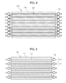
- FIG. 4 is a cross-sectional view taken along a direction A-A′ of FIG. 3 .
- FIG. 5 is a cross-sectional view taken along the direction A-A′ showing a water-cooling type secondary battery according to another embodiment of the present invention.
- FIG. 6 is a plan view showing a heat radiating plate according to the present invention.
- FIGS. 2 and 3 are an exploded perspective view and an assembly perspective view showing a water-cooling type secondary battery according to the present invention.
- a water-cooling type secondary battery 1000 includes a plurality battery cells 100 spaced apart from each other by a predetermined distance and formed in parallel with each other; and heat radiating plates 200 respectively interposed between the battery cells 100 and closely adhered to each other, and formed to be wider than an electrode body 110 of the battery cell 100 , wherein the heat radiating plate 200 has a refrigerant pipe 210 integrally formed on an edge thereof and is formed so that the refrigerant pipe 210 is disposed at an outer side of the electrode body 110 .
- the battery cells 100 are formed in parallel with each other to be spaced apart from each other by a predetermined distance, wherein the battery cell 100 has electrode tabs 120 formed at one side or both sides of the electrode body 110 formed in a plate shape, and the electrode tabs 120 of the battery cells 100 are electrically connected in series or in parallel with electrode tabs 120 of the battery cells 100 neighboring to each other.
- the heat radiating plates 200 formed in a plate shape are respectively interposed between the battery cells 100 and then closely adhered to each other, such that they are configured to allow heat generated during a process of charging or discharging the battery cells 100 to be quickly transferred to the heat radiating plates 200 .
- the heat radiating plate 200 may be made of a material having high heat conductivity such as aluminum or copper, and is preferably made of a material capable of quickly transferring the heat generated from the battery cell 100 thereto.
- the heat radiating plate 200 is formed to be wider than the electrode body 110 of the battery cell 100 .
- the heat radiating plate 200 has a refrigerant pipe 210 integrally formed on an edge thereof, such that the refrigerant pipe 210 is disposed at the outer side of the battery cell 100 .
- the refrigerant pipe 210 formed on the edge of the heat radiating plate 200 is formed in a form enclosing the outer side of the electrode body 110 of the battery cell 100 as shown in FIGS. 3 and 4 .
- the refrigerant pipe 210 has an inlet 211 and an outlet 212 respectively formed therein, such that a refrigerant may pass through the refrigerant pipe 210 and perform heat exchanging.
- FIGS. 2 and 3 show a form in which the inlet 211 and the outlet 212 are configured at one side of the heat radiating plate 200 , the formation of the inlet 211 and the outlet 212 may be variously changed depending on a shape of the battery cell 100 and a position at which the electrode tabs 120 are formed.
- the heat generated from the electrode body 110 upon charging or discharging the battery cells 100 is transferred to the refrigerant pipe 210 through the heat radiating plate 200 and transferred to the refrigerant passing through an inside of the refrigerant pipe 210 , thereby cooling the battery cell 100 .
- the heat radiating plate 200 and the refrigerant pipe 210 are separately formed and they are then assembled and coupled to each other, since a contact is not perfectly made at the coupled portion, heat conductivity is degraded, and in the case in which they are coupled to each other by a welding, since it is difficult to weld the heat radiating plate 200 and the refrigerant pipe 210 to be perfectly in contact with each other and deformation of the heat radiating plate 200 is caused by the welding, it is unlikely to perfectly adhere the heat radiating plate 200 to battery cell 100 . Therefore, since the heat radiating plate 200 and the refrigerant pipe 210 according to the present invention are integrally formed to thereby improve heat conductivity, the cooling efficiency is increased.
- the water-cooling type secondary battery 1000 includes a sub-module 500 formed by interposing the heat radiating plate 200 between a pair of battery cells 100 and closely adhering the heat radiating plate 200 and the battery cells 100 to each other, the sub-module 500 being stacked in plural, wherein the heat radiating plate 200 is formed to be wider than the electrode body 110 of the battery cell 100 and has the refrigerant pipe 210 integrally formed on the edge thereof, such that the refrigerant pipe 210 may be disposed at an outer side of the electrode body 110 .
- this has the same configuration as the above-mentioned embodiment that the heat radiating plate 200 is formed to be wider than the electrode body 110 of the battery cell 100 and the refrigerant pipe 210 is formed on the edge of the heat radiating plate 200 , but has a configuration that one heat radiating plate 200 per two battery cells 100 is interposed between the battery cells 100 and adhered to each other.
- the secondary battery 1000 is configured in a form in which the heat radiating plate 200 is alternately interposed between the stacked battery cells 100 .
- one secondary battery 1000 may be configured by stacking the plurality of sub-modules 500 including the heat radiating plate 200 , it is possible to conveniently assemble.
- a diameter of the refrigerant pipe 210 formed on the edge of the heat radiating plate 200 may be formed to be greater than that of the former embodiment, the cooling efficiency may be increased.
- the secondary battery 1000 formed to be stacked as described in the former and latter embodiments may further include an inlet manifold 300 connected to the inlets 211 of the refrigerant pipes 210 and having an inlet pipe 310 formed on one side thereof and an outlet manifold 400 connected to the outlets 212 of the refrigerant pipes 210 and having an outlet pipe 410 formed on one side thereof.
- the refrigerant introduced through the inlet pipe 310 flows along the inlet manifold 300 , is introduced the respective inlets 211 , passes through the plurality of refrigerant pipes 210 , performs the heat exchanging, is discharged to the respective outlets 212 , is collected in the outlet manifold 400 , and is then discharged through the outlet pipe 410 , the plurality of battery cells 100 may be uniformly cooled.
- the inlet 211 and the outlet 212 may be configured to be connected to a heat exchanger which is separately configured by a hose or a pipe, cool the refrigerant by passing the refrigerant heated during the circulation in the refrigerant pipe 210 through the heat exchanger, and then allow the cooled refrigerant to be again introduced into the refrigerant pipe 210 .
- the refrigerant water may be used, and a separation refrigerant having high heat exchanging efficiency may be used according to characteristics and uses of the battery.
- a metal plate having a clad layer formed on one surface thereof is press-machined to form a groove in an edge, two plates formed as described above are coupled to face each other and are then brazed, the clad layer is melted and welded, and the grooves facing each other are formed as the refrigerant pipe, such that the heat radiating plate integrally formed with the refrigerant pipe may be manufactured.
- the metal plate is press-machined to form the groove in the edge, and the refrigerant pipe having the clad layer formed at the outer side to correspond to a shape of the groove is manufactured to be inserted into the groove and then be brazed, such that the refrigerant pipe and the metal plate may be integrally formed.
Landscapes
- Engineering & Computer Science (AREA)
- Manufacturing & Machinery (AREA)
- Chemical & Material Sciences (AREA)
- Chemical Kinetics & Catalysis (AREA)
- Electrochemistry (AREA)
- General Chemical & Material Sciences (AREA)
- Physics & Mathematics (AREA)
- Thermal Sciences (AREA)
- Mechanical Engineering (AREA)
- General Engineering & Computer Science (AREA)
- Secondary Cells (AREA)
Abstract
Description
| [Detailed Description of Main Elements] |
| 1000: water-cooling type secondary battery according | |
| to present invention | |
| 100: battery cell | |
| 110: electrode body | 120: electrode tab |
| 200: heat radiating plate | |
| 210: refrigerant pipe | |
| 211: inlet | 212: outlet |
| 300: inlet manifold | 310: inlet pipe |
| 400: outlet manifold | 410: outlet pipe |
| 500: sub-module | |
Claims (6)
Applications Claiming Priority (3)
| Application Number | Priority Date | Filing Date | Title |
|---|---|---|---|
| KR10-2011-0128464 | 2011-12-02 | ||
| KR1020110128464A KR101750066B1 (en) | 2011-12-02 | 2011-12-02 | Water-cooled type secondary battery |
| PCT/KR2012/010246 WO2013081396A1 (en) | 2011-12-02 | 2012-11-29 | Water-cooling type secondary battery |
Publications (2)
| Publication Number | Publication Date |
|---|---|
| US20140335390A1 US20140335390A1 (en) | 2014-11-13 |
| US10514209B2 true US10514209B2 (en) | 2019-12-24 |
Family
ID=48535780
Family Applications (1)
| Application Number | Title | Priority Date | Filing Date |
|---|---|---|---|
| US14/362,171 Active 2034-01-19 US10514209B2 (en) | 2011-12-02 | 2012-11-29 | Water-cooling type secondary battery |
Country Status (4)
| Country | Link |
|---|---|
| US (1) | US10514209B2 (en) |
| KR (1) | KR101750066B1 (en) |
| CN (1) | CN103959554B (en) |
| WO (1) | WO2013081396A1 (en) |
Families Citing this family (47)
| Publication number | Priority date | Publication date | Assignee | Title |
|---|---|---|---|---|
| US20140120390A1 (en) * | 2012-10-31 | 2014-05-01 | Lg Chem, Ltd. | Battery cell assembly and method for manufacturing a cooling fin for the battery cell assembly |
| DE102013210585A1 (en) * | 2013-06-07 | 2014-12-11 | Robert Bosch Gmbh | Housing device for at least one energy storage cell and method for producing a housing device for at least one energy storage cell |
| KR101601149B1 (en) | 2013-10-17 | 2016-03-08 | 주식회사 엘지화학 | Heat sink having 2 or more separated cooling way |
| KR101642326B1 (en) | 2013-10-18 | 2016-07-26 | 주식회사 엘지화학 | Heat sink having 2 or more separated cooling way with vertical placemented common gateway |
| KR101601142B1 (en) | 2013-10-18 | 2016-03-08 | 주식회사 엘지화학 | Heat sink having 2 or more separated cooling way with insulation material |
| US9444124B2 (en) * | 2014-01-23 | 2016-09-13 | Lg Chem, Ltd. | Battery cell assembly and method for coupling a cooling fin to first and second cooling manifolds |
| US10084218B2 (en) | 2014-05-09 | 2018-09-25 | Lg Chem, Ltd. | Battery pack and method of assembling the battery pack |
| US10770762B2 (en) | 2014-05-09 | 2020-09-08 | Lg Chem, Ltd. | Battery module and method of assembling the battery module |
| KR101833526B1 (en) | 2014-05-29 | 2018-02-28 | 주식회사 엘지화학 | Battery Module Having Water-Cooled Type Cooling Structure |
| KR102321512B1 (en) * | 2014-09-11 | 2021-11-04 | 현대모비스 주식회사 | Water-cooled battery cooling apparatus using water-cooled battery module |
| KR101840417B1 (en) * | 2014-09-15 | 2018-03-20 | 주식회사 엘지화학 | Battery Module Comprising Cooling Structure having Minimized Bending of Coolant Channel |
| CN105990620A (en) * | 2015-02-10 | 2016-10-05 | 广东万锦科技股份有限公司 | Phase-change material rod |
| CN107615567A (en) * | 2015-02-18 | 2018-01-19 | Ttb控股有限公司 | Li-ion battery module with cooling system |
| EP3266056B1 (en) | 2015-03-06 | 2020-07-15 | Sterling PBES Energy Solutions Ltd. | Battery module with thermal runaway and gas exhaust management system |
| KR101780037B1 (en) * | 2015-04-22 | 2017-09-19 | 주식회사 엘지화학 | Cooling device for battery cell and battery module comprising the same |
| KR102324346B1 (en) | 2015-04-29 | 2021-11-10 | 삼성에스디아이 주식회사 | Cooling system for battery |
| CN104993183B (en) * | 2015-05-22 | 2017-10-03 | 江苏科技大学 | A kind of battery module, battery modules and battery modules method for packing |
| US9995535B2 (en) | 2015-06-30 | 2018-06-12 | Faraday&Future Inc. | Heat pipe for vehicle energy-storage systems |
| US10505163B2 (en) * | 2015-06-30 | 2019-12-10 | Faraday & Future Inc. | Heat exchanger for vehicle energy-storage systems |
| US9960465B2 (en) | 2015-07-30 | 2018-05-01 | Lg Chem, Ltd. | Battery pack |
| DE102015217780A1 (en) * | 2015-09-17 | 2017-03-23 | Robert Bosch Gmbh | Method for producing a cooling device for cooling batteries |
| KR102259414B1 (en) | 2015-11-20 | 2021-06-01 | 주식회사 엘지에너지솔루션 | Heat sink and battery module including the same |
| US10469209B2 (en) | 2016-02-01 | 2019-11-05 | Ofinno, Llc | Downlink control information in a wireless device and wireless network |
| US10477528B2 (en) | 2016-02-02 | 2019-11-12 | Ofinno, Llc | Downlink control information in a wireless device and wireless network |
| US10511413B2 (en) | 2016-02-03 | 2019-12-17 | Ofinno, Llc | Hybrid automatic repeat requests in a wireless device and wireless network |
| KR102413433B1 (en) | 2016-07-13 | 2022-06-28 | 에스케이온 주식회사 | Battery module |
| CN208045659U (en) | 2016-12-06 | 2018-11-02 | Sk新技术株式会社 | secondary battery module |
| CN106602170A (en) * | 2016-12-16 | 2017-04-26 | 中国矿业大学 | Variable contact-type battery heat management system |
| CN106941200A (en) * | 2017-03-14 | 2017-07-11 | 深圳市丰顺泰和投资合伙企业(有限合伙) | Soft-package battery radiating water cooling board and battery modules |
| CN107394310B (en) * | 2017-08-01 | 2019-09-03 | 天津市捷威动力工业有限公司 | Power battery cooling structure and system |
| CN107895823B (en) * | 2017-09-29 | 2019-09-27 | 北京北交新能科技有限公司 | A kind of lithium ion battery temprature control method |
| GB2570300B (en) * | 2018-01-17 | 2020-11-25 | Siemens Ag | Energy storage system |
| KR102080148B1 (en) | 2018-03-16 | 2020-02-21 | 박지암 | Liquid cooled type heat dissipating apparatus |
| KR102277035B1 (en) | 2018-03-21 | 2021-07-13 | 주식회사 엘지에너지솔루션 | Battery module, battery pack comprising the battery module and vehicle comprising the battery pack |
| KR20200027709A (en) | 2018-09-05 | 2020-03-13 | 현대모비스 주식회사 | Battery module of electric vehicle |
| KR102358425B1 (en) | 2018-09-18 | 2022-02-03 | 주식회사 엘지에너지솔루션 | Battery module |
| CN109638378B (en) * | 2018-11-15 | 2021-08-31 | 江苏科技大学 | A thermal management device for a battery power system of a new energy vehicle |
| KR102686568B1 (en) * | 2018-12-20 | 2024-07-19 | 주식회사 엘지에너지솔루션 | Battery pack |
| KR20200140011A (en) * | 2019-06-05 | 2020-12-15 | 주식회사 엘지화학 | Battery rack and energy storage system comprising the same |
| KR102930876B1 (en) * | 2020-04-29 | 2026-02-24 | 주식회사 엘지에너지솔루션 | Battery Pack and Electronic Device Comprising the Same and Vehicle |
| KR102172449B1 (en) * | 2020-06-05 | 2020-10-30 | 김광섭 | Fire diffusion prevention apparatus for battery system using latent heat of phase change material, and battery system including the same |
| CN111934047B (en) * | 2020-06-09 | 2024-03-29 | 江苏久泰电池科技有限公司 | Novel soft package battery module |
| CN113745694B (en) * | 2021-08-24 | 2023-05-26 | 三一重工股份有限公司 | Battery module and vehicle |
| KR102667183B1 (en) * | 2021-12-27 | 2024-05-17 | 주식회사 엘지에너지솔루션 | Battery module, battery pack the battery module, energy storage system and vehicle comprising the battery pack |
| KR20240028583A (en) * | 2022-08-24 | 2024-03-05 | 주식회사 엘지에너지솔루션 | Battery module and battery pack including the same |
| WO2024136007A1 (en) * | 2022-12-23 | 2024-06-27 | 주식회사 엘지에너지솔루션 | Battery pack and vehicle comprising same |
| JP2024171023A (en) * | 2023-05-29 | 2024-12-11 | トヨタ紡織株式会社 | Secondary battery |
Citations (6)
| Publication number | Priority date | Publication date | Assignee | Title |
|---|---|---|---|---|
| JP3426701B2 (en) | 1994-05-31 | 2003-07-14 | 株式会社東芝 | Fuel cell |
| JP2009009889A (en) | 2007-06-29 | 2009-01-15 | Sanyo Electric Co Ltd | Power supply for vehicle |
| KR20100119499A (en) | 2009-04-30 | 2010-11-09 | 주식회사 엘지화학 | Battery systems, battery module, and method for cooling a battery module |
| WO2011013905A2 (en) | 2009-07-27 | 2011-02-03 | 주식회사 엘지화학 | Battery module having improved cooling efficiency |
| KR20110126765A (en) | 2010-05-18 | 2011-11-24 | 주식회사 엘지화학 | Cooling member of novel structure and battery module including same |
| KR20110126764A (en) | 2010-05-18 | 2011-11-24 | 주식회사 엘지화학 | Compact and excellent cooling member and battery module comprising the same |
-
2011
- 2011-12-02 KR KR1020110128464A patent/KR101750066B1/en active Active
-
2012
- 2012-11-29 CN CN201280058750.3A patent/CN103959554B/en active Active
- 2012-11-29 US US14/362,171 patent/US10514209B2/en active Active
- 2012-11-29 WO PCT/KR2012/010246 patent/WO2013081396A1/en not_active Ceased
Patent Citations (11)
| Publication number | Priority date | Publication date | Assignee | Title |
|---|---|---|---|---|
| JP3426701B2 (en) | 1994-05-31 | 2003-07-14 | 株式会社東芝 | Fuel cell |
| JP2009009889A (en) | 2007-06-29 | 2009-01-15 | Sanyo Electric Co Ltd | Power supply for vehicle |
| KR20100119499A (en) | 2009-04-30 | 2010-11-09 | 주식회사 엘지화학 | Battery systems, battery module, and method for cooling a battery module |
| WO2011013905A2 (en) | 2009-07-27 | 2011-02-03 | 주식회사 엘지화학 | Battery module having improved cooling efficiency |
| US20120107664A1 (en) * | 2009-07-27 | 2012-05-03 | Lg Chem, Ltd. | Battery module of improved cooling efficiency |
| US8323819B2 (en) | 2009-07-27 | 2012-12-04 | Lg Chem, Ltd. | Battery module of improved cooling efficiency |
| KR20110126765A (en) | 2010-05-18 | 2011-11-24 | 주식회사 엘지화학 | Cooling member of novel structure and battery module including same |
| KR20110126764A (en) | 2010-05-18 | 2011-11-24 | 주식회사 엘지화학 | Compact and excellent cooling member and battery module comprising the same |
| WO2011145830A2 (en) | 2010-05-18 | 2011-11-24 | 주식회사 엘지화학 | Compact cooling member having superior stability, and battery module comprising same |
| US20130045410A1 (en) * | 2010-05-18 | 2013-02-21 | Lg Chem. Ltd. | Cooling member of compact structure and excellent stability and battery module employed with the same |
| US9077058B2 (en) | 2010-05-18 | 2015-07-07 | Lg Chem, Ltd. | Cooling member of compact structure and excellent stability and battery module employed with the same |
Non-Patent Citations (1)
| Title |
|---|
| Yang et al., Cooling Member of Novel Structure and Battery Module Employed with the Same, Nov. 27, 2012, K-PION machine translation (Year: 2012). * |
Also Published As
| Publication number | Publication date |
|---|---|
| WO2013081396A1 (en) | 2013-06-06 |
| KR20130062056A (en) | 2013-06-12 |
| CN103959554B (en) | 2017-11-14 |
| CN103959554A (en) | 2014-07-30 |
| US20140335390A1 (en) | 2014-11-13 |
| KR101750066B1 (en) | 2017-06-23 |
Similar Documents
| Publication | Publication Date | Title |
|---|---|---|
| US10514209B2 (en) | Water-cooling type secondary battery | |
| JP7098191B2 (en) | Battery module | |
| US11316216B2 (en) | Modular heat exchangers for battery thermal modulation | |
| JP5490241B2 (en) | Battery module including a heat dissipation member having a novel structure and medium- or large-sized battery pack | |
| JP5577459B2 (en) | Cooling member having compact structure and excellent stability, and battery module having the same | |
| JP5448119B2 (en) | Battery module with improved cooling efficiency | |
| US8802264B2 (en) | Easy-to-assemble battery pack with prismatic battery cells | |
| JP6106679B2 (en) | Electric energy accumulator | |
| JP5157681B2 (en) | Stacked cooler | |
| US9520626B2 (en) | Expandable stacked plate heat exchanger for a battery unit | |
| JP5866373B2 (en) | Battery pack with excellent cooling efficiency | |
| US8906533B2 (en) | Battery module | |
| JP6124512B2 (en) | Battery module | |
| US20130045411A1 (en) | Cooling device | |
| JP6997673B2 (en) | Battery pack | |
| JP2016157670A (en) | Battery pack | |
| CA2953412A1 (en) | Multi-sided heat exchangers with compliant heat transfer surfaces | |
| US9666894B2 (en) | Battery module and method for manufacturing the same | |
| JP5656706B2 (en) | Battery temperature control device | |
| KR20150128360A (en) | Cooling system for battery module | |
| JP6528689B2 (en) | Battery pack | |
| WO2012138833A2 (en) | Cooling assembly and method of control | |
| JP5751190B2 (en) | Battery pack | |
| JP2012186344A (en) | Heat exchanger | |
| CN115498309A (en) | battery pack |
Legal Events
| Date | Code | Title | Description |
|---|---|---|---|
| AS | Assignment |
Owner name: SK INNOVATION CO., LTD., KOREA, REPUBLIC OF Free format text: ASSIGNMENT OF ASSIGNORS INTEREST;ASSIGNORS:HWANG, JAE IL;LIM, DONG HUN;REEL/FRAME:033006/0305 Effective date: 20140528 |
|
| STPP | Information on status: patent application and granting procedure in general |
Free format text: RESPONSE TO NON-FINAL OFFICE ACTION ENTERED AND FORWARDED TO EXAMINER |
|
| STPP | Information on status: patent application and granting procedure in general |
Free format text: FINAL REJECTION MAILED |
|
| STPP | Information on status: patent application and granting procedure in general |
Free format text: RESPONSE AFTER FINAL ACTION FORWARDED TO EXAMINER |
|
| STPP | Information on status: patent application and granting procedure in general |
Free format text: NOTICE OF ALLOWANCE MAILED -- APPLICATION RECEIVED IN OFFICE OF PUBLICATIONS |
|
| STPP | Information on status: patent application and granting procedure in general |
Free format text: PUBLICATIONS -- ISSUE FEE PAYMENT VERIFIED |
|
| STCF | Information on status: patent grant |
Free format text: PATENTED CASE |
|
| AS | Assignment |
Owner name: SK ON CO., LTD., KOREA, REPUBLIC OF Free format text: NUNC PRO TUNC ASSIGNMENT;ASSIGNOR:SK INNOVATION CO., LTD.;REEL/FRAME:062034/0198 Effective date: 20220930 Owner name: SK INNOVATION CO., LTD., KOREA, REPUBLIC OF Free format text: CHANGE OF ADDRESS;ASSIGNOR:SK INNOVATION CO., LTD.;REEL/FRAME:061895/0380 Effective date: 20111031 |
|
| MAFP | Maintenance fee payment |
Free format text: PAYMENT OF MAINTENANCE FEE, 4TH YEAR, LARGE ENTITY (ORIGINAL EVENT CODE: M1551); ENTITY STATUS OF PATENT OWNER: LARGE ENTITY Year of fee payment: 4 |