US10509302B2 - Short throw projector mount with adjustable screw drive - Google Patents
Short throw projector mount with adjustable screw drive Download PDFInfo
- Publication number
- US10509302B2 US10509302B2 US15/568,721 US201615568721A US10509302B2 US 10509302 B2 US10509302 B2 US 10509302B2 US 201615568721 A US201615568721 A US 201615568721A US 10509302 B2 US10509302 B2 US 10509302B2
- Authority
- US
- United States
- Prior art keywords
- projector
- adjustment assembly
- mode
- yaw
- mount
- Prior art date
- Legal status (The legal status is an assumption and is not a legal conclusion. Google has not performed a legal analysis and makes no representation as to the accuracy of the status listed.)
- Active, expires
Links
Images


Classifications
-
- G—PHYSICS
- G03—PHOTOGRAPHY; CINEMATOGRAPHY; ANALOGOUS TECHNIQUES USING WAVES OTHER THAN OPTICAL WAVES; ELECTROGRAPHY; HOLOGRAPHY
- G03B—APPARATUS OR ARRANGEMENTS FOR TAKING PHOTOGRAPHS OR FOR PROJECTING OR VIEWING THEM; APPARATUS OR ARRANGEMENTS EMPLOYING ANALOGOUS TECHNIQUES USING WAVES OTHER THAN OPTICAL WAVES; ACCESSORIES THEREFOR
- G03B21/00—Projectors or projection-type viewers; Accessories therefor
- G03B21/14—Details
- G03B21/145—Housing details, e.g. position adjustments thereof
-
- G—PHYSICS
- G03—PHOTOGRAPHY; CINEMATOGRAPHY; ANALOGOUS TECHNIQUES USING WAVES OTHER THAN OPTICAL WAVES; ELECTROGRAPHY; HOLOGRAPHY
- G03B—APPARATUS OR ARRANGEMENTS FOR TAKING PHOTOGRAPHS OR FOR PROJECTING OR VIEWING THEM; APPARATUS OR ARRANGEMENTS EMPLOYING ANALOGOUS TECHNIQUES USING WAVES OTHER THAN OPTICAL WAVES; ACCESSORIES THEREFOR
- G03B21/00—Projectors or projection-type viewers; Accessories therefor
- G03B21/54—Accessories
-
- F—MECHANICAL ENGINEERING; LIGHTING; HEATING; WEAPONS; BLASTING
- F16—ENGINEERING ELEMENTS AND UNITS; GENERAL MEASURES FOR PRODUCING AND MAINTAINING EFFECTIVE FUNCTIONING OF MACHINES OR INSTALLATIONS; THERMAL INSULATION IN GENERAL
- F16M—FRAMES, CASINGS OR BEDS OF ENGINES, MACHINES OR APPARATUS, NOT SPECIFIC TO ENGINES, MACHINES OR APPARATUS PROVIDED FOR ELSEWHERE; STANDS; SUPPORTS
- F16M11/00—Stands or trestles as supports for apparatus or articles placed thereon ; Stands for scientific apparatus such as gravitational force meters
- F16M11/02—Heads
- F16M11/04—Means for attachment of apparatus; Means allowing adjustment of the apparatus relatively to the stand
- F16M11/06—Means for attachment of apparatus; Means allowing adjustment of the apparatus relatively to the stand allowing pivoting
- F16M11/10—Means for attachment of apparatus; Means allowing adjustment of the apparatus relatively to the stand allowing pivoting around a horizontal axis
-
- F—MECHANICAL ENGINEERING; LIGHTING; HEATING; WEAPONS; BLASTING
- F16—ENGINEERING ELEMENTS AND UNITS; GENERAL MEASURES FOR PRODUCING AND MAINTAINING EFFECTIVE FUNCTIONING OF MACHINES OR INSTALLATIONS; THERMAL INSULATION IN GENERAL
- F16M—FRAMES, CASINGS OR BEDS OF ENGINES, MACHINES OR APPARATUS, NOT SPECIFIC TO ENGINES, MACHINES OR APPARATUS PROVIDED FOR ELSEWHERE; STANDS; SUPPORTS
- F16M11/00—Stands or trestles as supports for apparatus or articles placed thereon ; Stands for scientific apparatus such as gravitational force meters
- F16M11/02—Heads
- F16M11/04—Means for attachment of apparatus; Means allowing adjustment of the apparatus relatively to the stand
- F16M11/06—Means for attachment of apparatus; Means allowing adjustment of the apparatus relatively to the stand allowing pivoting
- F16M11/12—Means for attachment of apparatus; Means allowing adjustment of the apparatus relatively to the stand allowing pivoting in more than one direction
-
- F—MECHANICAL ENGINEERING; LIGHTING; HEATING; WEAPONS; BLASTING
- F16—ENGINEERING ELEMENTS AND UNITS; GENERAL MEASURES FOR PRODUCING AND MAINTAINING EFFECTIVE FUNCTIONING OF MACHINES OR INSTALLATIONS; THERMAL INSULATION IN GENERAL
- F16M—FRAMES, CASINGS OR BEDS OF ENGINES, MACHINES OR APPARATUS, NOT SPECIFIC TO ENGINES, MACHINES OR APPARATUS PROVIDED FOR ELSEWHERE; STANDS; SUPPORTS
- F16M11/00—Stands or trestles as supports for apparatus or articles placed thereon ; Stands for scientific apparatus such as gravitational force meters
- F16M11/02—Heads
- F16M11/18—Heads with mechanism for moving the apparatus relatively to the stand
-
- F—MECHANICAL ENGINEERING; LIGHTING; HEATING; WEAPONS; BLASTING
- F16—ENGINEERING ELEMENTS AND UNITS; GENERAL MEASURES FOR PRODUCING AND MAINTAINING EFFECTIVE FUNCTIONING OF MACHINES OR INSTALLATIONS; THERMAL INSULATION IN GENERAL
- F16M—FRAMES, CASINGS OR BEDS OF ENGINES, MACHINES OR APPARATUS, NOT SPECIFIC TO ENGINES, MACHINES OR APPARATUS PROVIDED FOR ELSEWHERE; STANDS; SUPPORTS
- F16M11/00—Stands or trestles as supports for apparatus or articles placed thereon ; Stands for scientific apparatus such as gravitational force meters
- F16M11/20—Undercarriages with or without wheels
- F16M11/2007—Undercarriages with or without wheels comprising means allowing pivoting adjustment
- F16M11/2035—Undercarriages with or without wheels comprising means allowing pivoting adjustment in more than one direction
- F16M11/2071—Undercarriages with or without wheels comprising means allowing pivoting adjustment in more than one direction for panning and rolling
-
- F—MECHANICAL ENGINEERING; LIGHTING; HEATING; WEAPONS; BLASTING
- F16—ENGINEERING ELEMENTS AND UNITS; GENERAL MEASURES FOR PRODUCING AND MAINTAINING EFFECTIVE FUNCTIONING OF MACHINES OR INSTALLATIONS; THERMAL INSULATION IN GENERAL
- F16M—FRAMES, CASINGS OR BEDS OF ENGINES, MACHINES OR APPARATUS, NOT SPECIFIC TO ENGINES, MACHINES OR APPARATUS PROVIDED FOR ELSEWHERE; STANDS; SUPPORTS
- F16M11/00—Stands or trestles as supports for apparatus or articles placed thereon ; Stands for scientific apparatus such as gravitational force meters
- F16M11/20—Undercarriages with or without wheels
- F16M11/24—Undercarriages with or without wheels changeable in height or length of legs, also for transport only, e.g. by means of tubes screwed into each other
-
- F—MECHANICAL ENGINEERING; LIGHTING; HEATING; WEAPONS; BLASTING
- F16—ENGINEERING ELEMENTS AND UNITS; GENERAL MEASURES FOR PRODUCING AND MAINTAINING EFFECTIVE FUNCTIONING OF MACHINES OR INSTALLATIONS; THERMAL INSULATION IN GENERAL
- F16M—FRAMES, CASINGS OR BEDS OF ENGINES, MACHINES OR APPARATUS, NOT SPECIFIC TO ENGINES, MACHINES OR APPARATUS PROVIDED FOR ELSEWHERE; STANDS; SUPPORTS
- F16M13/00—Other supports for positioning apparatus or articles; Means for steadying hand-held apparatus or articles
- F16M13/02—Other supports for positioning apparatus or articles; Means for steadying hand-held apparatus or articles for supporting on, or attaching to, an object, e.g. tree, gate, window-frame, cycle
- F16M13/027—Ceiling supports
Definitions
- the present invention relates to mounting devices and more specifically to adjustable mounts for projectors.
- Multi-media presentations performed with video projection equipment have become very common for business and entertainment purposes.
- the video projection equipment is a portable LCD projector that is placed on a table, cart, or stand in the room, with the image projected on a portion of the wall or a portable screen.
- Such impromptu arrangements have a number of drawbacks.
- a considerable amount of time is often needed to position, aim, and focus the projector in advance of the presentation—time that is expended repeatedly whenever a different projector is set up.
- it is often difficult to position a portable projector where it is not in the way of persons moving about in the room, or in the line of sight for those viewing the presentation.
- the wires and cables used to connect the projector with the computer are in the open at ground level, presenting a tripping hazard and an opportunity for damage to the projector if someone comes in contact with them.
- U.S. Pat. No. 5,490,655 a device for mounting a video/data projector from a ceiling or wall is disclosed in which struts are used to form channels for supporting the projector and to conceal cabling.
- the channels result in a rather bulky device that may be difficult to harmonize with the aesthetic environment of a presentation room.
- adjustment of the projector for roll, pitch, and yaw may be time consuming and difficult due to the generally limited adjustment capability of the device.
- the projector may be vulnerable to theft by anyone with common hand tools and access to the device during unattended hours.
- Other prior devices such as the low-profile LCD projector mount is disclosed in U.S. Pat. No. 6,042,068, offer a relatively more compact mount arrangement, but still offer only a limited range of projector pitch and yaw adjustment, and no roll adjustment at all.
- a projector mount is described in U.S. Pat. No. 7,156,359 (owned by the owners of the present invention and hereby fully incorporated by reference) which alleviates many of the problems of prior devices.
- the disclosed mount provides independent projector roll, pitch, and yaw adjustments along with theft deterrence in the form of coded fasteners connecting each separate portion of the mount. Fine adjustment for position may be hampered, however, due to the number of separate fasteners to be loosened and tightened to enable adjustment (six for the pitch and roll adjustments), and by the tendency for the weight of the projector to pull the mount out of adjustment unless the projector is held in the desired position.
- the theft resistant security fasteners inhibit theft of the device, convenience of use of the projector device is compromised by the need to remove the security fasteners with a special tool in order to move the projector to a new location.
- a projector mount for attaching a projection device to an overhead structure which includes a device interface operably attachable to the projection device with a plurality of fasteners.
- the device interface has a first portion and a second portion slidably disposed on the first portion.
- the first and second portions together define a plurality of retaining structures, each retaining structure for receiving a separate one of the plurality of fasteners.
- the second portion is selectively slidably shiftable relative to the first portion between a first latched position wherein each of the plurality of fasteners is received and retained in a separate one of the retaining structures and a second unlatched position wherein the plurality of fasteners is freely disengagable from the retaining structures.
- Embodiments of the present invention meet the need in the industry for a projector mount combining the features of relatively quick and easy precision projector position adjustment in roll, pitch, and yaw, orientations, high security and theft deterrence, and compact size.
- embodiments of the present invention provide a mount with controls enabling quick selection between course alignment of a projector by hand about any of the three positioning axes—pitch, yaw, and roll—and precision adjustment of projector position about any one or more of the axes, once the course alignment has been made.
- embodiments of the present invention save time, and cost, in the installation of projectors.
- a mount for a projector includes a support structure interface and a projector interface, the projector interface and the support structure interface coupled by an adjustment mechanism including at least a pitch adjustment assembly, and a roll adjustment assembly.
- At least one of the pitch adjustment assembly or the roll adjustment assembly may include a control mechanism, the control mechanism enabling selection between a first mode in which the projector is positionable about a rotation axis by hand, and a second mode in which the projector is positionable about the rotation axis using the pitch adjustment assembly or the roll adjustment assembly.
- the pitch adjustment assembly or the roll adjustment assembly may include a rotatable lead screw, and the projector is positioned about the rotation axis in the second mode by rotating the lead screw.
- control mechanism includes a rotatable knob, and rotation of the rotatable knob shifts the control mechanism between the first mode and the second mode.
- the projector interface further includes a yaw adjustment assembly.
- the yaw adjustment assembly can include a control mechanism, the control mechanism enabling selection between a first mode in which the projector is positionable about the yaw axis by hand, and a second mode in which the projector is positionable about the yaw axis using the yaw adjustment assembly.
- the yaw adjustment assembly includes a rotatable lead screw, and the projector is positioned about the yaw axis in the second mode by rotating the lead screw.
- the control mechanism of the yaw mechanism can include a rotatable knob, wherein rotation of the rotatable knob shifts the control mechanism between the first mode and the second mode.
- the mount includes a support structure assembly operably coupled to the support structure interface.
- the support structure assembly can include an arm assembly, the support structure interface being selectively positionable along the arm assembly to adjust a distance of the projector from a screen.
- the support structure interface may be operably coupled to the support structure assembly with a column so as to enable selective vertical shifting of the support structure interface relative to the support structure assembly.
- a projection system includes a projector; and a mount for attaching the projector to a structure, the mount including a support structure interface, and a projector interface, the projector interface and the support structure interface coupled by an adjustment mechanism including at least a pitch adjustment assembly, and a roll adjustment assembly.
- At least one of the pitch adjustment assembly or the roll adjustment assembly includes a control mechanism, the control mechanism enabling selection between a first mode in which the projector is positionable about a rotation axis by hand, and a second mode in which the projector is positionable about the rotation axis using the pitch adjustment assembly or the roll adjustment assembly.
- the pitch adjustment assembly or the roll adjustment assembly may include a rotatable lead screw, wherein the projector is positioned about the rotation axis in the second mode by rotating the lead screw.
- the control mechanism may include a rotatable knob, wherein rotation of the rotatable knob shifts the control mechanism between the first mode and the second mode.
- the system may further include a yaw adjustment assembly.
- the yaw adjustment assembly may further include a control mechanism, the control mechanism enabling selection between a first mode in which the projector is positionable about the yaw axis by hand, and a second mode in which the projector is positionable about the yaw axis using the yaw adjustment assembly.
- the yaw adjustment assembly may include a rotatable lead screw, with the projector being positioned about the yaw axis in the second mode by rotating the lead screw.
- the control mechanism of the yaw mechanism can include a rotatable knob, wherein rotation of the rotatable knob shifts the control mechanism between the first mode and the second mode.
- a mount for a projector includes a support structure interface and a projector interface, the projector interface and the support structure interface coupled by an adjustment mechanism including at least one adjustment assembly for adjusting the projector about at least one rotation axis, the adjustment assembly including a control mechanism, the control mechanism enabling selection between a first mode in which the projector is positionable about the at least one rotation axis by hand, and a second mode in which the projector is positionable about the at least one rotation axis using the adjustment assembly.
- FIG. 1 is an isometric view of a projector mount according to an embodiment of the invention
- FIG. 1A is an isometric cross-section view taken at section A-A of FIG. 1 ;
- FIG. 1B is a right elevation view of FIG. 1A ;
- FIG. 1C is an isometric cross-section view taken at section C-C of FIG. 1 ;
- FIG. 1D is a front elevation view of FIG. 1C ;
- FIG. 2 is a top plan view of the mount of FIG. 1 ;
- FIG. 3 is a bottom plan view of the mount of FIG. 1 ;
- FIG. 4 is a front elevation view of the mount of FIG. 1 ;
- FIG. 5 is a right elevation view of the mount of FIG. 1 ;
- FIG. 6 is a rear elevation view of the mount of FIG. 1 ;
- FIG. 7 is a left elevation view of the mount of FIG. 1 ;
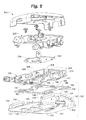
- FIG. 8 is an isometric exploded view of the mount of FIG. 1 , with select elements removed for clarity;
- FIG. 9 is another view of FIG. 8 ;
- FIG. 10 is another view of FIG. 8 ;
- FIG. 11 is an isometric view of the projector mount of FIG. 1 , depicted with the top cover and side covers removed;
- FIG. 12 is another view of FIG. 11 ;
- FIG. 13 is an isometric view of an upper frame of a projector mount, depicted with device orientation adjustment assemblies;
- FIG. 14 is another view of FIG. 13 ;
- FIG. 15 is an isometric view of an upper frame of a projector mount
- FIG. 16 is an isometric view of an intermediate frame, a base plate, locking plate and lock assembly portions of a projector mount;
- FIG. 17 is an isometric view of an intermediate frame, depicted with a device orientation adjustment assembly
- FIG. 18 is another isometric view of an intermediate frame
- FIG. 19 is an isometric view of a base plate, locking plate and lock assembly portions of a projector mount
- FIG. 20 is an isometric view of a device orientation adjustment assembly
- FIG. 21 is an isometric exploded view of another device orientation adjustment assembly
- FIG. 22 is a close-up view of portions of FIG. 21 ;
- FIG. 23 is an isometric cross-section taken at section X-X of FIG. 22 ;
- FIG. 24 is an isometric view of an adjustment selector
- FIG. 25 is a front elevation view of FIG. 24 ;
- FIG. 26 is an isometric exploded view of portions of a device orientation adjustment assembly with the adjustment selector depicted in an alternate position;
- FIG. 27 is a rear elevation view of FIG. 26 ;
- FIG. 28 is a right elevation view of the portions of FIG. 26 assembled together;
- FIG. 29 is a right elevation view of FIG. 26 ;
- FIG. 30 is an isometric view of a projector secured to a projector mount and support structure assembly, according to an embodiment of the invention.
- FIG. 31 is another isometric view of FIG. 30 ;
- the Figures may designate, for reference purposes, the relative directions of x-y-z coordinate axes as applied to the invention. Any reference herein to movement in an x-axis direction, a y-axis direction, or a z-axis direction, or to rotation about an x-axis, a y-axis or a z-axis, relates to these coordinate axes.
- the x-axis is oriented fore-and-aft in relation to the mounted device, the z-axis is vertical, and the y-axis is oriented laterally from side-to-side in relation to the mounted device and perpendicular to the x-axis and the z-axis.
- roll is defined as angular displacement about the x-axis
- pitch is defined as angular displacement about the y-axis
- yaw is defined as angular displacement about the z-axis.
- projector mount 100 generally includes a base assembly 102 , an intermediate frame 200 , an upper frame 240 , at least one device orientation adjustment assembly 260 , a support structure interface 300 and an optional cover 320 .
- Projector mount 100 may include three device orientation adjustment assemblies, as depicted in the Figures, in the form of yaw adjustment assembly 260 y , roll adjustment assembly 260 r , and pitch adjustment assembly 260 p . In other embodiments not pictured, projector mount 100 may be provided with fewer than three device orientation adjustment assemblies.
- base assembly 102 generally includes a base plate 104 , a locking plate 106 , and an optional lock mechanism 110 .
- Base plate 104 includes an upper surface 102 , an opposing lower surface 122 configured to be positioned proximate a projector 400 , a first upright 124 and a second upright 130 , each of the uprights being generally transverse to a plane defined by upper surface 120 and lower surface 122 .
- First upright 124 includes an aperture 126 configured to accommodate a lock 180 of lock mechanism 110 , and a plurality of slots 128 .
- Second upright 130 includes a channel 132 configured to provide clearance for a portion of a device orientation adjustment assembly 260 , as well as a plurality of slots 134 .
- Each of slots 128 , 134 are configured to cooperate with pitch adjustment assembly 260 p as described in more detail below.
- Base plate 104 further includes a support means 136 for a device orientation adjustment assembly 260 , the support means 136 including a channel 138 configured to provide clearance for a portion of the device orientation adjustment assembly. Disposed in base plate 104 are a plurality of keyhole apertures 140 , each aperture 140 including an enlarged portion 142 and a channel portion 144 . Keyhole apertures 140 are configured to receive button-head fasteners 402 of projector 400 .
- a plurality of stops 146 are included in base plate 104 , extending generally transverse from upper surface 102 . Stops 146 are configured to limit movement of locking plate 106 , and include a stem portion extending to a flared top portion.
- base assembly 102 may include covers 152 removably coupled with uprights 124 , 130 to provide an aesthetically pleasing appearance to base assembly 102 as well as prevent any possible injury to a user while adjusting projector mount 100 by covering arcuate slots 128 , 134 .
- locking plate 106 generally includes an upper surface 160 , a lower surface 162 , a notch 164 , and a channel 166 . Further included in locking plate 106 is a plurality of keyhole apertures 168 , each aperture 168 including an enlarged portion 170 and a channel portion 172 .
- Locking plate 106 is movable between an unlocked position and a locked position. In the unlocked position, apertures 168 of locking plate 106 are aligned with apertures 140 of base plate 104 such that fasteners 402 of projector 400 can be accepted by projector mount 100 . In the locked position, locking plate 106 is translated with respect to base plate 104 such that fasteners 402 of projector 400 are secured between channel portion 144 of base plate 104 and channel portion 172 of locking plate 172 , such as depicted in FIGS. 1, 11-12, 16 and 19 .
- a control lever 174 which includes a lever portion 176 and a flange portion, is provided to operably move locking plate 106 between the unlocked position and the locked position.
- Control lever 174 is rotatably coupled to base plate 104 in an off-center arrangement.
- Flange portion of control lever 174 is configured to engage aperture 166 of locking plate 166 , such that operation of control lever 174 causes locking plate 106 to be moved between the unlocked position and the locked position.
- Lock mechanism 110 includes a lock portion 180 configured to be coupled to aperture 126 of first upright 124 of base plate 104 , and a lock arm 182 actuated by lock 180 .
- Lock 180 may be configured to be operable by a unique key, a screwdriver, or other suitable means.
- Lock arm 182 is selectively engageable with control lever 174 and channel 166 of locking plate 106 so as to maintain locking plate 106 in the locked position and engaged with fasteners 402 of projector 400 , as depicted in FIGS. 17 and 18 .
- intermediate frame 200 includes a first side 202 , a second side 206 , a third side 210 and a fourth side 218 .
- first side 202 and second side 206 include respective tabs 204 , 208 having bores 209 defined therein which facilitate adjustably coupling intermediate frame 200 to base plate 104 by way of slots 128 , 134 defined in uprights 124 , 130 , respectively to provide pitch adjustment of projector mount 100 .
- Suitable fasteners for coupling intermediate frame 200 to base plate 104 may include bolts, screws, rivets, or similar structures extending through bores 209 and slots 128 , 134 which enable intermediate frame 200 to be adjustably positioned with respect to base plate 104 .
- the third side 210 of intermediate frame 200 includes a plurality of slots 212 defined therein, and support means 214 , 215 configured to receive roll adjustment assembly 260 r , each of support means 214 , 215 including respective channels 216 , 217 configured to provide clearance for a portion of roll adjustment assembly 260 r .
- the fourth side 218 of intermediate frame 200 includes a plurality of slots 220 disposed therein, each of slots 212 , 220 being configured to cooperate with roll adjustment assembly 260 r as described in more detail below.
- Intermediate frame 200 further includes pitch adjustment receiving means 222 , in the form of bores 224 disposed in each of third side 210 and fourth side 218 , configured to receive a portion of pitch adjustment assembly 260 p.
- upper frame 240 includes a yaw adjustment receiving means 242 , a roll adjustment receiving means 244 , a plurality of tabs 246 having bores disposed therein which facilitate adjustably coupling upper frame 240 and intermediate frame 200 by way of slots 212 , 220 to provide roll adjustment of projector mount 100 .
- Suitable fasteners for coupling upper frame 240 to intermediate frame 200 may comprise bolts, screws, rivets, or similar which allow upper frame 240 to be adjustably positioned with respect to intermediate frame 200 .
- Also included in upper frame 240 is a plurality of slots 248 which facilitate adjustably coupling intermediate frame 200 and upper frame 240 to provide yaw adjustment of projector mount 100 .
- projector mount 100 includes one or more device orientation adjustment assemblies 260 , such as pitch adjustment assembly 260 p , roll adjustment assembly 260 r , and/or yaw adjustment assembly 260 y .
- Each device orientation adjustment assembly 260 p , 260 r , 260 y is configured to provide macro and micro adjustability of the position of projector mount 100 .
- each of device orientation adjustment assemblies 260 p , 260 r , 260 y includes a body 262 having a longitudinal bore 264 with tube 268 oriented transverse to, and intersecting, longitudinal bore 264 .
- Tube 268 defines an inner bore 270 , with a transverse slot 272 at a distal end of tube 268 .
- Body 262 is pinned in position between structures in mount 100 via a pin 271 received in slot 272 so as to prevent rotation of body 262 about inner bore 270 .
- An adjustment selector 276 is provided for switching device orientation adjustment assembly 260 between a macro (or coarse) adjustment mode, and a micro (or fine) adjustment mode.
- Adjustment selector 276 is received in tube 268 and includes a knob 278 and a shaft 282 .
- Shaft 282 is received in inner bore 270 of tube 268 , with shaft 282 including a first non-threaded bore 284 defined by a first axis 286 , and a second intersecting threaded bore 288 defined by a second axis 290 .
- first axis 286 and second axis 290 are separated by an angle ⁇ .
- ⁇ is approximately forty-five degrees, although other angles may be used.
- a threaded lead screw 292 is received through first bore 284 and second bore 288 , and has one or more locknuts 294 and a knob 296 . As will be described below, by rotating adjustment selector 276 , threaded lead screw 292 is selectively engageable with the threads of threaded bore 288 in order to enable either course or fine adjustment of pitch, roll, and yaw of a projector 400 attached to projector mount 100 .
- Each of device orientation adjustment assemblies 260 is configured for both macro and micro adjustability of the position of projector mount 100 , with adjustment selector 276 being operable to switch between macro and micro adjustment modes.
- first bore 284 is aligned with longitudinal bore 264 of body 262 , such that lead screw 292 is disengaged from body 262 , tube 268 and adjustment selector 276 .
- the orientation of projector 400 may be adjusted by simply grasping projector 400 and urging projector 400 in the desired direction of adjustment. Once the approximate orientation of projector 400 is achieved, adjustment selector 276 is moved to the micro adjustment mode for final orientation of projector 400 .
- adjustment selector 276 is oriented such that second bore 288 is aligned with longitudinal bore 264 of body 262 and so that the threads of lead screw 292 are engaged with threads 291 in second bore 288 .
- the orientation of projector 400 may be adjusted by rotating lead screw 292 via knob 296 .
- the orientation of projector 400 is fixed unless knob 296 is operated due to engagement of the threads of lead screw 292 with threads 291 in shaft 282 .
- Projector mount 100 further includes a support structure interface 300 , including a plate 300 having a plurality of bores 304 therein, fasteners 306 , a yaw adjustment coupling means 308 , and means 310 for coupling with a support structure.
- Support structure interface 300 is operably coupleable to slots 248 of upper frame 240 and operably coupleable to yaw adjustment assembly 260 via means 308 .
- Support structure interface 300 is configured to couple with a support structure assembly 330 , such as a ceiling or wall mount, as depicted in FIGS. 30 and 31 .
- Support structure assembly 330 as depicted in FIGS. 30 and 31 , generally includes wall interface 450 , body portion 452 , which includes rails 454 , 456 , and distal end member 458 , as well as rail interface 460 , and column 462 .
- Rails 454 , 456 extend between wall interface 450 and distal end member 458 .
- Each rail 454 , 456 presents an upwardly directed flange 464 .
- Rail interface 460 generally includes base plate 466 with downwardly oriented flanges 468 at opposing edges, so as to overlap flanges 464 .
- Base plate 466 is selectively slidable on rails 454 , 456 along a longitudinal axis Z-Z of support structure assembly 330 .
- Base plate 464 can be secured to rails 454 , 456 in a selected position along axis Z-Z with wing nuts 470 coupled with associated clamps (not depicted).
- Rail interface 460 further includes column interface 472 which is selectively rotatably coupled to base plate 466 via fasteners 474 which are slidable in slots 476 defined in base plate 464 .
- Fasteners 474 can be loosened to permit rotation of column interface 472 relative to base plate 464 , or tightened to fix column interface 472 in place relative to base plate 464 .
- Column interface 472 includes upstanding cylindrical portion 478 defining bore 480 , receiving column 462 therethrough.
- Column 462 is slidably movable in bore 480 , but can be fixed in a selected vertical position with fasteners 482 extending through cylindrical portion 478 and apertures 484 in column 462 .
- Column 462 is fixed to support structure interface 300 .
- projector mount 100 is operable to adjust the orientation of projector 400 in one or more of roll, pitch and yaw with respect to the fixed reference point of support structure assembly 330 .
- pitch adjustment assembly 260 p lead screw 292 is coupled to intermediate frame 200 via bores 224 disposed in third side 210 and fourth side 218 of intermediate frame 200 .
- tube 268 of pitch adjustment assembly 260 p is coupled to base plate 104 via second upright 130 and support upright 136 .
- Pitch adjustment assembly 260 p provides adjustment of pitch between base plate 104 and intermediate frame 200 , such that adjustment of pitch adjustment assembly 260 p causes projector 400 , base plate 104 and locking plate 106 to pitch with respect to intermediate frame 200 , upper frame 240 , support structure interface 300 and support structure assembly 330 .
- roll adjustment assembly 260 r lead screw 292 is coupled to upper frame 240 via roll adjustment receiving means 244 .
- tube 268 of roll adjustment assembly 260 r is coupled to intermediate frame 200 via support uprights 214 , 215 .
- Roll adjustment assembly 260 r therefore provides adjustment of roll between intermediate frame 200 and upper frame 240 , such that adjustment of roll adjustment assembly 260 r causes projector 400 , base plate 104 , locking plate 106 and intermediate frame 200 to roll with respect to upper frame 240 , support structure interface 300 , and support structure assembly 330 .
- yaw adjustment assembly 260 y lead screw 292 is coupled to upper frame 240 via yaw adjustment receiving means 242 .
- tube 268 of yaw adjustment assembly 260 y is coupled to support structure interface 300 via a pin or rivet secured between slot 272 on tube 268 and yaw adjustment coupling means 308 on support structure interface 300 .
- Yaw adjustment assembly 260 y therefore provides adjustment of yaw between upper frame 240 and support structure interface 300 , such that adjustment of yaw adjustment assembly 260 y causes projector 400 , base plate 104 , locking plate 106 , intermediate frame 200 and upper frame 240 to yaw with respect to support structure interface 300 and support structure assembly 330 .
- projector mount 100 and projector 400 can be moved closer to, or away from, a projection screen 500 by sliding base plate 464 on rails 454 , 456 along the longitudinal axis X 1 -X 1 of support structure assembly 330 , and securing it in the desired position.
- Projector 400 can be moved in a vertical direction relative to projection screen 500 by sliding column 462 in bore 480 and securing column 480 in position with fasteners 482 .
- Projector 400 can be still further adjusted in yaw by rotating column interface 472 relative to base plate 466 , and fixing it in place in the desired position with fasteners 474 . In this way, yaw, vertical position, and spacing of projector 400 relative to projection screen 400 can be independently adjusted via support structure interface 330 .
Landscapes
- Engineering & Computer Science (AREA)
- General Engineering & Computer Science (AREA)
- Mechanical Engineering (AREA)
- Physics & Mathematics (AREA)
- General Physics & Mathematics (AREA)
- Projection Apparatus (AREA)
- Transforming Electric Information Into Light Information (AREA)
Abstract
Description
Claims (13)
Priority Applications (1)
| Application Number | Priority Date | Filing Date | Title |
|---|---|---|---|
| US15/568,721 US10509302B2 (en) | 2015-04-23 | 2016-04-25 | Short throw projector mount with adjustable screw drive |
Applications Claiming Priority (3)
| Application Number | Priority Date | Filing Date | Title |
|---|---|---|---|
| US201562151789P | 2015-04-23 | 2015-04-23 | |
| PCT/US2016/029262 WO2016172732A1 (en) | 2015-04-23 | 2016-04-25 | Short throw projector mount with adjustable screw drive |
| US15/568,721 US10509302B2 (en) | 2015-04-23 | 2016-04-25 | Short throw projector mount with adjustable screw drive |
Publications (2)
| Publication Number | Publication Date |
|---|---|
| US20180136547A1 US20180136547A1 (en) | 2018-05-17 |
| US10509302B2 true US10509302B2 (en) | 2019-12-17 |
Family
ID=57144275
Family Applications (1)
| Application Number | Title | Priority Date | Filing Date |
|---|---|---|---|
| US15/568,721 Active 2036-07-03 US10509302B2 (en) | 2015-04-23 | 2016-04-25 | Short throw projector mount with adjustable screw drive |
Country Status (5)
| Country | Link |
|---|---|
| US (1) | US10509302B2 (en) |
| EP (1) | EP3286481A4 (en) |
| CN (1) | CN107690600B (en) |
| CA (1) | CA2983766C (en) |
| WO (1) | WO2016172732A1 (en) |
Cited By (2)
| Publication number | Priority date | Publication date | Assignee | Title |
|---|---|---|---|---|
| US20220185198A1 (en) * | 2020-12-11 | 2022-06-16 | Marelli Europe S.P.A. | Fixing Assembly |
| US11402057B1 (en) * | 2021-03-18 | 2022-08-02 | Oxti Corporation | Securely mountable/dismountable electronic equipment support stand |
Families Citing this family (8)
| Publication number | Priority date | Publication date | Assignee | Title |
|---|---|---|---|---|
| WO2019107482A1 (en) | 2017-11-30 | 2019-06-06 | 富士フイルム株式会社 | Projector |
| CN107991833B (en) * | 2017-12-25 | 2020-04-14 | 重庆锐正科技有限公司 | Projector system |
| CN109973794B (en) * | 2019-04-17 | 2024-05-28 | 杭州德昌视讯科技有限公司 | Projector bracket |
| CN111336374B (en) * | 2020-03-16 | 2024-08-09 | 杭州迈杰教育科技有限公司 | Angle correction mechanism and projector bracket with same |
| DE102020108831A1 (en) | 2020-03-31 | 2021-09-30 | Airbus Operations Gmbh | Fastening system for attaching a projector in an aircraft cabin, method for maintaining and / or attaching a projector and method for adjusting a projector |
| CN116086829B (en) * | 2023-03-20 | 2026-03-06 | 深圳市道通科技股份有限公司 | A car calibration device |
| IT202300021726A1 (en) * | 2023-10-18 | 2025-04-18 | Euromet S R L | PROJECTOR ADJUSTMENT SYSTEM. |
| CN117739231A (en) * | 2023-12-21 | 2024-03-22 | 长春长光睿视光电技术有限责任公司 | Six-degree-of-freedom rotation calibration mechanism |
Citations (19)
| Publication number | Priority date | Publication date | Assignee | Title |
|---|---|---|---|---|
| US4473291A (en) | 1983-03-24 | 1984-09-25 | Opti-Copy, Inc. | Support arrangement for track mounted cameras, projectors and camera/projectors |
| US5253834A (en) * | 1992-02-19 | 1993-10-19 | Grumman Aerospace Corporation | Alignment fixture for unobstructed pivot point |
| US5938161A (en) * | 1996-06-14 | 1999-08-17 | Nec Corporation | Projection installing device |
| US6042068A (en) * | 1997-09-04 | 2000-03-28 | Peerless Indsutries, Inc. | Low profile LCD projector mount |
| WO2000044063A1 (en) | 1999-01-20 | 2000-07-27 | Nokia Networks Oy | An adjustment joint, fastening elements and a method for installation and position setting using an adjustment joint |
| US6485144B1 (en) * | 2000-08-30 | 2002-11-26 | Jung-Huang Liao | Projector hanger frame |
| US6883920B2 (en) * | 2002-12-19 | 2005-04-26 | Coretronic Corporation | Adjusting apparatus |
| US20050161575A1 (en) * | 2004-01-23 | 2005-07-28 | Steven Friederich | Universal projector mount |
| US7156359B2 (en) * | 2003-04-11 | 2007-01-02 | Csav, Inc. | Secure mounting system for overhead mounted projector |
| EP1852646A2 (en) | 2006-05-05 | 2007-11-07 | CSAV, Inc. | Adjustable projector mount with quick release device interface |
| US20080179475A1 (en) | 2007-01-19 | 2008-07-31 | Peerless Industries, Inc. | Projector mount |
| US7891624B2 (en) * | 2006-05-05 | 2011-02-22 | Milestone Av Technologies Llc | Adjustable projector mount |
| US20110162468A1 (en) | 2010-01-06 | 2011-07-07 | Yu-Jen Lin | Coarse/fine adjustment linear displacement mechanism |
| US8033519B2 (en) * | 2008-05-29 | 2011-10-11 | Mike David | Projector mount with Phillips screw driver angle adjustment |
| US20110297809A1 (en) * | 2010-06-08 | 2011-12-08 | Bouissiere Michael F | Projector mount with micro adjustment |
| US8138469B2 (en) * | 2008-06-12 | 2012-03-20 | Milestone Av Technologies Llc | Universal projector interface having at least one arm assembly including an elongate arm member and a shiftable coupling portion with sustainable alignment |
| US20120224152A1 (en) | 2011-03-03 | 2012-09-06 | Panamorph, Inc. | Overhead support system for a light projection system |
| US8573551B2 (en) | 2011-08-31 | 2013-11-05 | Modernsolid Industrial Co., Ltd. | Fine-adjusting apparatus for an overhead projector |
| US20140077053A1 (en) | 2012-09-17 | 2014-03-20 | Delta Electronics, Inc. | Projector mount |
Family Cites Families (5)
| Publication number | Priority date | Publication date | Assignee | Title |
|---|---|---|---|---|
| JPH07102413A (en) | 1993-09-16 | 1995-04-18 | Japan Gore Tex Inc | Polytetrafluoroethylene filament |
| DE102006033506B4 (en) * | 2006-07-19 | 2008-07-03 | Infineon Technologies Ag | Schottky contact device and its use |
| CN200982510Y (en) * | 2006-12-13 | 2007-11-28 | 四川川大智胜软件股份有限公司 | Six freedom degree separate regulation projector hanger |
| CA2890013A1 (en) * | 2012-11-05 | 2014-05-08 | Milestone Av Technologies Llc | Short throw projector mount with micro-adjust feature |
| CN203189989U (en) * | 2013-03-05 | 2013-09-11 | 江门市盈江科技有限公司 | Installation support of projector device |
-
2016
- 2016-04-25 US US15/568,721 patent/US10509302B2/en active Active
- 2016-04-25 CN CN201680031785.6A patent/CN107690600B/en not_active Expired - Fee Related
- 2016-04-25 CA CA2983766A patent/CA2983766C/en not_active Expired - Fee Related
- 2016-04-25 EP EP16784111.3A patent/EP3286481A4/en not_active Withdrawn
- 2016-04-25 WO PCT/US2016/029262 patent/WO2016172732A1/en not_active Ceased
Patent Citations (22)
| Publication number | Priority date | Publication date | Assignee | Title |
|---|---|---|---|---|
| US4473291A (en) | 1983-03-24 | 1984-09-25 | Opti-Copy, Inc. | Support arrangement for track mounted cameras, projectors and camera/projectors |
| US5253834A (en) * | 1992-02-19 | 1993-10-19 | Grumman Aerospace Corporation | Alignment fixture for unobstructed pivot point |
| US5938161A (en) * | 1996-06-14 | 1999-08-17 | Nec Corporation | Projection installing device |
| US6042068A (en) * | 1997-09-04 | 2000-03-28 | Peerless Indsutries, Inc. | Low profile LCD projector mount |
| WO2000044063A1 (en) | 1999-01-20 | 2000-07-27 | Nokia Networks Oy | An adjustment joint, fastening elements and a method for installation and position setting using an adjustment joint |
| US6485144B1 (en) * | 2000-08-30 | 2002-11-26 | Jung-Huang Liao | Projector hanger frame |
| US6883920B2 (en) * | 2002-12-19 | 2005-04-26 | Coretronic Corporation | Adjusting apparatus |
| US7156359B2 (en) * | 2003-04-11 | 2007-01-02 | Csav, Inc. | Secure mounting system for overhead mounted projector |
| US20050161575A1 (en) * | 2004-01-23 | 2005-07-28 | Steven Friederich | Universal projector mount |
| US20110108692A1 (en) | 2006-05-05 | 2011-05-12 | Jay Dittmer | Adjustable projector mount |
| EP1852646A2 (en) | 2006-05-05 | 2007-11-07 | CSAV, Inc. | Adjustable projector mount with quick release device interface |
| US7891624B2 (en) * | 2006-05-05 | 2011-02-22 | Milestone Av Technologies Llc | Adjustable projector mount |
| US20080179475A1 (en) | 2007-01-19 | 2008-07-31 | Peerless Industries, Inc. | Projector mount |
| US8033519B2 (en) * | 2008-05-29 | 2011-10-11 | Mike David | Projector mount with Phillips screw driver angle adjustment |
| US8138469B2 (en) * | 2008-06-12 | 2012-03-20 | Milestone Av Technologies Llc | Universal projector interface having at least one arm assembly including an elongate arm member and a shiftable coupling portion with sustainable alignment |
| US20110162468A1 (en) | 2010-01-06 | 2011-07-07 | Yu-Jen Lin | Coarse/fine adjustment linear displacement mechanism |
| US20110297809A1 (en) * | 2010-06-08 | 2011-12-08 | Bouissiere Michael F | Projector mount with micro adjustment |
| US20120224152A1 (en) | 2011-03-03 | 2012-09-06 | Panamorph, Inc. | Overhead support system for a light projection system |
| US8894222B2 (en) * | 2011-03-03 | 2014-11-25 | Panamorph, Inc. | Overhead support system for a light projection system |
| US8573551B2 (en) | 2011-08-31 | 2013-11-05 | Modernsolid Industrial Co., Ltd. | Fine-adjusting apparatus for an overhead projector |
| US20140077053A1 (en) | 2012-09-17 | 2014-03-20 | Delta Electronics, Inc. | Projector mount |
| US9164364B2 (en) * | 2012-09-17 | 2015-10-20 | Delta Electronics, Inc | Projector mount |
Non-Patent Citations (3)
| Title |
|---|
| Canadian Office Action for Application No. 2,983,766 dated Aug. 28, 2018 (3 pgs). |
| Extended European Search Report for Application No. 16784111.3, dated Dec. 10, 2018 (8 pgs). |
| International Search Report and Written Opinion for Application No. PCT/US2016/029262, dated Jul. 28, 2016. |
Cited By (3)
| Publication number | Priority date | Publication date | Assignee | Title |
|---|---|---|---|---|
| US20220185198A1 (en) * | 2020-12-11 | 2022-06-16 | Marelli Europe S.P.A. | Fixing Assembly |
| US11685318B2 (en) * | 2020-12-11 | 2023-06-27 | Marelli Europe S.P.A. | Fixing assembly |
| US11402057B1 (en) * | 2021-03-18 | 2022-08-02 | Oxti Corporation | Securely mountable/dismountable electronic equipment support stand |
Also Published As
| Publication number | Publication date |
|---|---|
| CN107690600B (en) | 2021-03-05 |
| CN107690600A (en) | 2018-02-13 |
| EP3286481A1 (en) | 2018-02-28 |
| CA2983766A1 (en) | 2016-10-27 |
| CA2983766C (en) | 2020-10-06 |
| EP3286481A4 (en) | 2019-01-09 |
| WO2016172732A1 (en) | 2016-10-27 |
| US20180136547A1 (en) | 2018-05-17 |
Similar Documents
| Publication | Publication Date | Title |
|---|---|---|
| US10509302B2 (en) | Short throw projector mount with adjustable screw drive | |
| US7988119B2 (en) | Adjustable projector mount | |
| US7497412B2 (en) | Adjustable projector mount with quick release device interface | |
| US7503536B2 (en) | Universal projector mount | |
| US9851047B1 (en) | Pull-out swivel mount | |
| US8282059B2 (en) | Incremental angular position and locking system for mounting devices | |
| US8523129B2 (en) | Adjustabale display mount | |
| US7090182B2 (en) | Appliance mounting device | |
| US20080068784A1 (en) | Moveable Display Mount | |
| CN108468918B (en) | A display screen mounting bracket and display device | |
| US20110101179A1 (en) | Tv support structure with latching mechanism | |
| US20070278361A1 (en) | Adjustable support arm for video monitor | |
| US20050207101A1 (en) | Display device having an adjustable display screen | |
| CN101421670A (en) | Universal projector mount |
Legal Events
| Date | Code | Title | Description |
|---|---|---|---|
| FEPP | Fee payment procedure |
Free format text: ENTITY STATUS SET TO UNDISCOUNTED (ORIGINAL EVENT CODE: BIG.); ENTITY STATUS OF PATENT OWNER: LARGE ENTITY |
|
| STPP | Information on status: patent application and granting procedure in general |
Free format text: DOCKETED NEW CASE - READY FOR EXAMINATION |
|
| STPP | Information on status: patent application and granting procedure in general |
Free format text: NON FINAL ACTION MAILED |
|
| STPP | Information on status: patent application and granting procedure in general |
Free format text: RESPONSE TO NON-FINAL OFFICE ACTION ENTERED AND FORWARDED TO EXAMINER |
|
| STPP | Information on status: patent application and granting procedure in general |
Free format text: NOTICE OF ALLOWANCE MAILED -- APPLICATION RECEIVED IN OFFICE OF PUBLICATIONS |
|
| AS | Assignment |
Owner name: MILESTONE AV TECHNOLOGIES LLC, MINNESOTA Free format text: ASSIGNMENT OF ASSIGNORS INTEREST;ASSIGNOR:SCHUH, MATHEW;REEL/FRAME:050344/0180 Effective date: 20190909 |
|
| AS | Assignment |
Owner name: LEGRAND AV INC., MINNESOTA Free format text: ASSIGNMENT OF ASSIGNORS INTEREST;ASSIGNOR:MILESTONE AV TECHNOLOGIES INC.;REEL/FRAME:050979/0562 Effective date: 20181221 |
|
| STPP | Information on status: patent application and granting procedure in general |
Free format text: PUBLICATIONS -- ISSUE FEE PAYMENT VERIFIED |
|
| STCF | Information on status: patent grant |
Free format text: PATENTED CASE |
|
| MAFP | Maintenance fee payment |
Free format text: PAYMENT OF MAINTENANCE FEE, 4TH YEAR, LARGE ENTITY (ORIGINAL EVENT CODE: M1551); ENTITY STATUS OF PATENT OWNER: LARGE ENTITY Year of fee payment: 4 |