US10507559B2 - Machine tool and brake checking method - Google Patents
Machine tool and brake checking method Download PDFInfo
- Publication number
- US10507559B2 US10507559B2 US15/511,304 US201515511304A US10507559B2 US 10507559 B2 US10507559 B2 US 10507559B2 US 201515511304 A US201515511304 A US 201515511304A US 10507559 B2 US10507559 B2 US 10507559B2
- Authority
- US
- United States
- Prior art keywords
- brakes
- movable part
- machine tool
- brake
- driving motor
- Prior art date
- Legal status (The legal status is an assumption and is not a legal conclusion. Google has not performed a legal analysis and makes no representation as to the accuracy of the status listed.)
- Expired - Fee Related, expires
Links
Images


Classifications
-
- B—PERFORMING OPERATIONS; TRANSPORTING
- B23—MACHINE TOOLS; METAL-WORKING NOT OTHERWISE PROVIDED FOR
- B23Q—DETAILS, COMPONENTS, OR ACCESSORIES FOR MACHINE TOOLS, e.g. ARRANGEMENTS FOR COPYING OR CONTROLLING; MACHINE TOOLS IN GENERAL CHARACTERISED BY THE CONSTRUCTION OF PARTICULAR DETAILS OR COMPONENTS; COMBINATIONS OR ASSOCIATIONS OF METAL-WORKING MACHINES, NOT DIRECTED TO A PARTICULAR RESULT
- B23Q17/00—Arrangements for observing, indicating or measuring on machine tools
- B23Q17/007—Arrangements for observing, indicating or measuring on machine tools for managing machine functions not concerning the tool
-
- B—PERFORMING OPERATIONS; TRANSPORTING
- B23—MACHINE TOOLS; METAL-WORKING NOT OTHERWISE PROVIDED FOR
- B23Q—DETAILS, COMPONENTS, OR ACCESSORIES FOR MACHINE TOOLS, e.g. ARRANGEMENTS FOR COPYING OR CONTROLLING; MACHINE TOOLS IN GENERAL CHARACTERISED BY THE CONSTRUCTION OF PARTICULAR DETAILS OR COMPONENTS; COMBINATIONS OR ASSOCIATIONS OF METAL-WORKING MACHINES, NOT DIRECTED TO A PARTICULAR RESULT
- B23Q15/00—Automatic control or regulation of feed movement, cutting velocity or position of tool or work
-
- B—PERFORMING OPERATIONS; TRANSPORTING
- B23—MACHINE TOOLS; METAL-WORKING NOT OTHERWISE PROVIDED FOR
- B23Q—DETAILS, COMPONENTS, OR ACCESSORIES FOR MACHINE TOOLS, e.g. ARRANGEMENTS FOR COPYING OR CONTROLLING; MACHINE TOOLS IN GENERAL CHARACTERISED BY THE CONSTRUCTION OF PARTICULAR DETAILS OR COMPONENTS; COMBINATIONS OR ASSOCIATIONS OF METAL-WORKING MACHINES, NOT DIRECTED TO A PARTICULAR RESULT
- B23Q5/00—Driving or feeding mechanisms; Control arrangements therefor
- B23Q5/22—Feeding members carrying tools or work
- B23Q5/34—Feeding other members supporting tools or work, e.g. saddles, tool-slides, through mechanical transmission
- B23Q5/38—Feeding other members supporting tools or work, e.g. saddles, tool-slides, through mechanical transmission feeding continuously
- B23Q5/40—Feeding other members supporting tools or work, e.g. saddles, tool-slides, through mechanical transmission feeding continuously by feed shaft, e.g. lead screw
-
- B—PERFORMING OPERATIONS; TRANSPORTING
- B23—MACHINE TOOLS; METAL-WORKING NOT OTHERWISE PROVIDED FOR
- B23Q—DETAILS, COMPONENTS, OR ACCESSORIES FOR MACHINE TOOLS, e.g. ARRANGEMENTS FOR COPYING OR CONTROLLING; MACHINE TOOLS IN GENERAL CHARACTERISED BY THE CONSTRUCTION OF PARTICULAR DETAILS OR COMPONENTS; COMBINATIONS OR ASSOCIATIONS OF METAL-WORKING MACHINES, NOT DIRECTED TO A PARTICULAR RESULT
- B23Q5/00—Driving or feeding mechanisms; Control arrangements therefor
- B23Q5/54—Arrangements or details not restricted to group B23Q5/02 or group B23Q5/22 respectively, e.g. control handles
- B23Q5/58—Safety devices
-
- F—MECHANICAL ENGINEERING; LIGHTING; HEATING; WEAPONS; BLASTING
- F16—ENGINEERING ELEMENTS AND UNITS; GENERAL MEASURES FOR PRODUCING AND MAINTAINING EFFECTIVE FUNCTIONING OF MACHINES OR INSTALLATIONS; THERMAL INSULATION IN GENERAL
- F16D—COUPLINGS FOR TRANSMITTING ROTATION; CLUTCHES; BRAKES
- F16D66/00—Arrangements for monitoring working conditions, e.g. wear, temperature
-
- F—MECHANICAL ENGINEERING; LIGHTING; HEATING; WEAPONS; BLASTING
- F16—ENGINEERING ELEMENTS AND UNITS; GENERAL MEASURES FOR PRODUCING AND MAINTAINING EFFECTIVE FUNCTIONING OF MACHINES OR INSTALLATIONS; THERMAL INSULATION IN GENERAL
- F16H—GEARING
- F16H25/00—Gearings comprising primarily only cams, cam-followers and screw-and-nut mechanisms
- F16H25/18—Gearings comprising primarily only cams, cam-followers and screw-and-nut mechanisms for conveying or interconverting oscillating or reciprocating motions
- F16H25/20—Screw mechanisms
- F16H25/22—Screw mechanisms with balls, rollers, or similar members between the co-operating parts; Elements essential to the use of such members
- F16H25/2204—Screw mechanisms with balls, rollers, or similar members between the co-operating parts; Elements essential to the use of such members with balls
-
- F—MECHANICAL ENGINEERING; LIGHTING; HEATING; WEAPONS; BLASTING
- F16—ENGINEERING ELEMENTS AND UNITS; GENERAL MEASURES FOR PRODUCING AND MAINTAINING EFFECTIVE FUNCTIONING OF MACHINES OR INSTALLATIONS; THERMAL INSULATION IN GENERAL
- F16H—GEARING
- F16H25/00—Gearings comprising primarily only cams, cam-followers and screw-and-nut mechanisms
- F16H25/18—Gearings comprising primarily only cams, cam-followers and screw-and-nut mechanisms for conveying or interconverting oscillating or reciprocating motions
- F16H25/20—Screw mechanisms
- F16H25/24—Elements essential to such mechanisms, e.g. screws, nuts
- F16H25/2454—Brakes; Rotational locks
-
- F—MECHANICAL ENGINEERING; LIGHTING; HEATING; WEAPONS; BLASTING
- F16—ENGINEERING ELEMENTS AND UNITS; GENERAL MEASURES FOR PRODUCING AND MAINTAINING EFFECTIVE FUNCTIONING OF MACHINES OR INSTALLATIONS; THERMAL INSULATION IN GENERAL
- F16D—COUPLINGS FOR TRANSMITTING ROTATION; CLUTCHES; BRAKES
- F16D2121/00—Type of actuator operation force
- F16D2121/18—Electric or magnetic
- F16D2121/20—Electric or magnetic using electromagnets
Definitions
- the present invention relates to a machine tool and a brake checking method for the machine tool.
- patent literature 1 discloses a technique which brakes a ball screw and sets 0 as a speed command to a servo motor at the same time when power supply is stopped.
- patent literature 2 discloses a mechanism which prevents a free fall by an electromagnetic brake when the power supply is turned off.
- patent literature 3 has disclosed a brake motor which stops the rotation of the motor shaft when no electric current is supplied.
- patent literature 4 discloses a technique which controls a brake apparatus first by delaying a power shutoff command, thereby braking a gravity axis.
- Patent literature 1 Japanese Patent No. 3472433
- Patent literature 2 Japanese Patent Laid-Open No. 2007-034653
- Patent literature 3 Japanese Patent Laid-Open No. 2007-181850
- Patent literature 4 Japanese Patent Laid-Open No. 2004-009168
- the present invention enables to provide a technique of solving the above-described problem.
- One aspect of the present invention provides a machine tool comprising
- Another aspect of the present invention provides a brake checking method for a machine tool including
- FIG. 1A is a view showing the arrangement of a machine tool according to the first embodiment of the present invention.
- FIG. 1B is a view showing the arrangement of the machine tool according to the first embodiment of the present invention.
- FIG. 2A is a perspective view showing the outer appearance of the arrangement of a machine tool according to the second embodiment of the present invention.
- FIG. 2B is a sectional view showing the arrangement of the machine tool according to the second embodiment of the present invention.
- FIG. 2C is an exploded view showing the arrangement of the machine tool according to the second embodiment of the present invention.
- FIG. 3 is an exploded view showing the arrangement of an electromagnetic brake according to the second embodiment of the present invention.
- FIG. 4 is a partially cutaway perspective view of the electromagnetic brake according to the second embodiment of the present invention.
- FIG. 5A is a view for explaining the operation of the electromagnetic brake according to the second embodiment of the present invention.
- FIG. 5B is a sectional view showing the arrangement of the electromagnetic brake according to the second embodiment of the present invention.
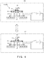
- FIG. 6 is a perspective view showing the outer appearance of an NC lathe according to the third embodiment of the present invention.
- FIG. 7 is a perspective view showing the outer appearance of the NC lathe according to the third embodiment of the present invention.
- FIG. 8 is a perspective view showing the outer appearance of a vertical machining center according to the fourth embodiment of the present invention.
- FIG. 9 is a perspective view of a moving mechanism unit of the vertical machining center according to the fourth embodiment of the present invention.
- FIGS. 1A and 1B A driving mechanism unit 100 of a machine tool as the first embodiment of the present invention will be explained with reference to FIGS. 1A and 1B .
- the driving mechanism unit 100 of the machine tool includes a ball screw 101 , a rotor 102 , a movable part 103 , at least two brakes 104 and 105 , a brake controller 106 , and a trouble detector 107 .
- FIGS. 1A and 1B show a brake motor incorporating the rotor 102 and brake 104 .
- FIGS. 1A and 1B show an arrangement in which the rotor 102 is coupled with the ball screw 101 via a toothed belt 108 as an example, but the present invention is not limited to this.
- the driving motor may also be coupled with the ball screw via a joint.
- the at least two brakes 104 and 105 form a mechanism of preventing a fall of the movable part 103 when power supply to the driving motor is stopped.
- a plurality of brakes are attached to one shaft in order to give redundancy to a safety function, i.e., fall prevention.
- the brake controller 106 When power supply to the driving motor is stopped, the brake controller 106 causes the at least two brakes 104 and 105 to function one by one. In a normal operation, “all” of the plurality of brakes are “simultaneously” operated. The purpose of releasing at least one brake is to check the brake function.
- the brake controller 106 releases all of the at least two brakes except one brake. For example, the brake controller 106 releases two brakes when there are three brakes, and releases three brakes when there are four brakes.
- the brake controller 106 stops power supply to the rotor 102 , and then releases at least one of the at least two brakes. That is, when powering off the driving mechanism unit 100 of the machining tool, the brake 104 or 105 is inspected.
- FIG. 1A shows a state in which the brake 105 is released while preventing the rotation of the shaft of the rotor 102 by operating the brake 104 . If the movable part 103 falls in this state, the trouble detector 107 can determine that the brake 104 has a trouble.
- FIG. 1B shows a state in which the brake 104 is released while preventing the rotation of the ball screw 101 by operating the brake 105 . If the movable part 103 falls in this state, the trouble detector 107 can determine that the brake 105 has a trouble.
- the trouble detector 107 causes the at least two brakes 104 to 105 to function one by one, thereby detecting the presence/absence of a fall of the movable part 103 or the fall distance of the movable part 103 , and detecting troubles of the at least two brakes 104 and 105 . That is, if the movable part 103 falls or the fall distance is equal to or larger than a predetermined value, the trouble detector 107 detects that the brake 104 or 105 has a trouble, and notifies the user of the trouble.
- FIG. 2A is a view for explaining the outer appearance of the driving mechanism unit 200 of the machine tool according to this embodiment
- FIG. 2B is a sectional view showing the internal arrangement of the driving mechanism unit 200 of the machine tool
- FIG. 2C is an exploded view of the driving mechanism unit 200 .
- the driving mechanism unit 200 of the machine tool according to this embodiment differs from the above-mentioned first embodiment in that a ball screw, electromagnetic brake, and driving motor are arranged on the same axis.
- a driving motor 221 does not incorporate any electromagnetic brake, and both of two electromagnetic brakes 105 and 224 are installed outside the driving motor 221 .
- a housing 202 is formed on the same axis as that of a ball screw 101 , and the electromagnetic brake 105 is formed between the housing 202 and the ball screw 101 .
- a movable part 203 is coupled with a ball nut 231 , and vertically moves along the ball screw 101 .
- a brake controller 106 controls power supply to the two electromagnetic brakes 105 and 224 inside and outside the housing 202 , thereby causing the electromagnetic brakes 105 and 224 to function one by one.
- a coupling 226 couples the ball screw 101 and the driving motor shaft.
- the electromagnetic brake 224 is formed below the coupling 226 . As shown in FIG.
- the housing 202 is a box for attaching the driving motor 221 , and the electromagnetic brake 224 and coupling 226 are accommodated in this box.
- An encoder 225 is attached to (incorporated into) the driving motor 221 , and functions as a rotation amount detector for detecting a rotation amount.
- the movable part 203 is coupled with the ball nut 231 .
- a trouble detector 107 determines the presence/absence of a trouble based on the rotational speed detected by the encoder 225 . That is, a state in which only the electromagnetic brake 105 is operated or a state in which only the electromagnetic brake 224 is operated is intentionally generated, and whether the ball screw 101 rotates when the electromagnetic brakes 105 and 224 are caused to function one by one is detected. If the ball screw 101 rotates, it is determined that the electromagnetic brake 105 or 224 has a trouble, and a special operator performs maintenance.
- FIGS. 3 and 4 are views for explaining the arrangement of the electromagnetic brakes 105 and 224 .
- FIG. 3 is an exploded view of the electromagnetic brake 105
- FIG. 4 is a function explaining view.
- the brake shown in FIGS. 3 and 4 is set in a fixed state or released state in accordance with whether (a magnet on) a rotating disk is attracted to or repelled from a coil.
- the distal end portion of the ball screw 101 is fixed to a gear 301 .
- the gear 301 meshes with a disk-like magnet 302 . Therefore, the magnet 302 rotates together with the ball screw 101 .
- a coil 303 is formed below the magnet 302 in FIG. 3 . When electric power is supplied to the coil 303 , the magnet 302 slightly separates from the coil 303 , so the ball screw 101 becomes rotatable (an upper state 401 in FIG. 4 ).
- FIGS. 5A and 5B show an example of an electromagnetic brake having another structure.
- the electromagnetic brake shown in FIG. 5A does not have a structure in which a rotating disk 502 itself is attracted to a coil 503 .
- This electromagnetic brake operates in a state in which the rotating disk 502 is pushed by a pushing plate 504 against a fixed plate 505 fixed outside the rotating disk 502 , or in a state in which the rotating disk 502 is not pushed but released.
- the pushing plate 504 is pushed by a spring and moves in the direction of the outside fixed plate 505 . Since the disk 502 is sandwiched between the pushing plate 504 and the fixed plate 505 , the rotating disk 502 is also sandwiched and fixed when the pushing plate 504 is pushed by the spring.
- the pushing plate 504 is attracted to the coil 503 against a spring 506 , so the rotating disk 502 is released.
- the electromagnetic brake does not function in some cases when the power supply is turned off. If this is the case, the movable part 203 moves down by gravity while rotating the ball screw 101 , and this is very dangerous. Accordingly, a mechanism which gives redundancy by attaching a plurality of electromagnetic brakes has been adopted. However, redundancy like this makes it difficult to find a trouble occurring in an electromagnetic brake. While the braking ability is sufficient, therefore, the trouble detector 107 determines a fall of the movable part 203 based on a rotation amount detected by the encoder 225 attached to the driving motor 221 , thereby detecting a trouble of the electromagnetic brake.
- the brake controller 106 When powering off the driving mechanism unit 200 of the machine tool, the brake controller 106 stops power supply to the driving motor 221 , and alternately releases at least one of the at least two electromagnetic brakes 105 and 224 . That is, the brake controller 106 inspects the electromagnetic brakes 105 and 224 when powering off the driving mechanism unit 200 of the machine tool. In addition, when powering on the whole matching tool or the whole driving mechanism unit 200 of the machine tool, the trouble detector 107 compares the fall distance of the movable part 203 since power-OFF with a predetermined threshold. If the movable part 203 has fallen more than the predetermined threshold, the trouble detector 107 determines that an unreleased electromagnetic brake of the at least two electromagnetic brakes 105 and 224 has a trouble.
- the encoder 225 determines a fall of the movable part 203 in this embodiment, but the present invention is not limited to this.
- FIG. 6 is a view showing the outer appearance of an NC (Numerical Control) lathe 600 as a machine tool according to this embodiment. Differences from the above-mentioned second embodiment are that the NC lathe 600 has a ball screw 601 in the Y-axis direction, and a tool rest 603 moves along the ball screw 601 . The rest of the arrangement and the operations are the same as those of the second embodiment, so the same reference numerals denote the same components and operations, and a detailed explanation thereof will be omitted.
- NC Numerical Control
- a Y-axis servo motor 602 vertically moves the tool rest 603 as a movable part along the ball screw 601 .
- an X-axis servo motor 612 moves a whole Y-axis moving mechanism in the X-axis direction. In a state in which the tool rest 603 has moved to a lower predetermined position, an object to be processed attached to a spindle head 606 is cut by a tool attached to the tool rest 603 .
- an electromagnetic brake 604 is formed immediately below the servo motor 602 so that the tool rest 603 does not freely fall while power supply is stopped.
- a second electromagnetic brake 605 is formed in the downstream end of the ball screw 601 .
- the electromagnetic brakes 604 and 605 are alternately operated and alternately turned off, and whether the moving distance of the tool rest 603 is equal to or larger than a predetermined value is determined by using encoders 622 and 623 . Troubles of the electromagnetic brakes 604 and 605 are detected in accordance with the determination result.
- FIG. 7 is a view showing the NC lathe 600 in the direction of an arrow 610 in FIG. 6 .
- FIG. 7 shows that the electromagnetic brake 604 is formed on the downstream side of the Y-axis servo motor 602 . At the same time power supply to the servo motor 602 stops, the electromagnetic brake 604 operates and stops the ball screw 601 .
- the present invention is applicable to an NC lathe.
- FIG. 8 is a view showing the overall outer appearance of a vertical machining center 800 .
- FIG. 9 is a view specifically showing a Z-axis-direction spindle moving mechanism incorporated into the vertical machining center 800 .
- a moving mechanism 801 for relatively moving the tool spindle and an object to be processed in the X-axis direction, Y-axis direction, and Z-axis direction is formed.
- the moving mechanism 801 includes a Z-direction moving mechanism 900 shown in FIG. 9 .
- the moving mechanism 900 includes two Z-axis servo motors 901 and 902 , and ball screws 903 and 904 to be rotated by these servo motors.
- a spindle head 905 as a movable part which vertically moves in the Z-axis direction as the ball screws 903 and 904 rotate is formed.
- the servo motors 901 and 902 respectively include electromagnetic brakes 906 and 907 , and hence are made redundant so as to reliably prevent the rotations of the two ball screws 903 and 904 even when power supply to the servo motors 901 and 902 stops.
- the electromagnetic brakes 906 and 907 and encoders 908 and 909 are respectively attached to the servo motors 901 and 902 .
- the electromagnetic brakes 906 and 907 grip the ball screws 903 and 904 so that they do not rotate.
- the encoders 908 and 909 detect the rotational angles of the rotating shafts of the servo motors connected to the ball screws, thereby detecting troubles of the electromagnetic brakes 906 and 907 .
- the present invention is also applicable to a vertical machining center.
Landscapes
- Engineering & Computer Science (AREA)
- Mechanical Engineering (AREA)
- General Engineering & Computer Science (AREA)
- Braking Arrangements (AREA)
- Auxiliary Devices For Machine Tools (AREA)
- Machine Tool Sensing Apparatuses (AREA)
- Transmission Devices (AREA)
Abstract
Description
-
- a ball screw extended in a vertical direction,
- a driving motor that rotates the ball screw,
- a movable part that vertically moves along the ball screw in accordance with the rotation of the ball screw driven by the driving motor,
- at least two brakes that prevent a fall of the movable part while power supply to the driving motor is stopped,
- a brake controller that releases at least one of the at least two brakes while power supply to the driving motor is stopped, and
- a detector that detects presence/absence of a fall of the movable part or a fall distance of the movable part resulting from the release of the at least one brake, thereby detecting a trouble of an unreleased one of the at least two brakes.
-
- a ball screw extended in a vertical direction,
- a driving motor that rotates the ball screw,
- a movable part that vertically moves along the ball screw in accordance with the rotation of the ball screw driven by the driving motor, and
- at least two brakes that prevent a fall of the movable part while power supply to the driving motor is stopped,
- the method comprising
- releasing at least one of the at least two brakes while power supply to the driving motor is stopped, and
- detecting a fall distance of the movable part resulting from the release of the at least one brake, thereby detecting a trouble of an unreleased one of the at least two brakes.
Claims (9)
Applications Claiming Priority (3)
| Application Number | Priority Date | Filing Date | Title |
|---|---|---|---|
| JP2014-190856 | 2014-09-19 | ||
| JP2014190856A JP5926782B2 (en) | 2014-09-19 | 2014-09-19 | Machine tool and brake check method |
| PCT/JP2015/067859 WO2016042874A1 (en) | 2014-09-19 | 2015-06-22 | Machine tool and brake checking method |
Publications (2)
| Publication Number | Publication Date |
|---|---|
| US20170291271A1 US20170291271A1 (en) | 2017-10-12 |
| US10507559B2 true US10507559B2 (en) | 2019-12-17 |
Family
ID=55532919
Family Applications (1)
| Application Number | Title | Priority Date | Filing Date |
|---|---|---|---|
| US15/511,304 Expired - Fee Related US10507559B2 (en) | 2014-09-19 | 2015-06-22 | Machine tool and brake checking method |
Country Status (6)
| Country | Link |
|---|---|
| US (1) | US10507559B2 (en) |
| EP (1) | EP3195975A4 (en) |
| JP (1) | JP5926782B2 (en) |
| KR (1) | KR20170061678A (en) |
| CN (1) | CN106715043B (en) |
| WO (1) | WO2016042874A1 (en) |
Families Citing this family (6)
| Publication number | Priority date | Publication date | Assignee | Title |
|---|---|---|---|---|
| JP6789271B2 (en) * | 2018-09-18 | 2020-11-25 | 株式会社Screenホールディングス | Board processing equipment |
| JP7285107B2 (en) * | 2019-03-28 | 2023-06-01 | シチズン時計株式会社 | Rotary tool equipment and machine tools |
| JP7562407B2 (en) * | 2020-12-28 | 2024-10-07 | ニデックインスツルメンツ株式会社 | ROBOT AND METHOD FOR CONTROLLING ROBOT |
| CN113560934B (en) * | 2021-09-07 | 2022-05-27 | 北京博鲁斯潘精密机床有限公司 | Accurate positioning and moving mechanism of precise numerical control machine tool |
| JP7550912B1 (en) | 2023-04-13 | 2024-09-13 | 株式会社牧野フライス製作所 | Method and device for determining abnormality in feed shaft clamping mechanism of machine tool |
| KR20250158091A (en) * | 2024-04-29 | 2025-11-06 | 주식회사 디엔솔루션즈 | Machine tool thrust maintenance device and its control method |
Citations (18)
| Publication number | Priority date | Publication date | Assignee | Title |
|---|---|---|---|---|
| US3931727A (en) | 1974-09-09 | 1976-01-13 | Verson Allsteel Press Company | Method and system for detecting brake wear in a metal forming machine |
| JPS53105776A (en) | 1977-02-25 | 1978-09-14 | Komatsu Ltd | Brake system for presses |
| JPH035100Y2 (en) | 1985-01-23 | 1991-02-08 | ||
| JPH0739190Y2 (en) | 1990-10-02 | 1995-09-06 | 古河電気工業株式会社 | Rotating connector |
| JPH10263973A (en) | 1997-03-24 | 1998-10-06 | Fanuc Ltd | Gravity shaft falling down prevention device at time of power failure |
| JP2003266278A (en) | 2002-03-05 | 2003-09-24 | Deckel Maho Pfronten Gmbh | Machine tool provided with brake means for machine part |
| JP2004009168A (en) | 2002-06-04 | 2004-01-15 | Toshiba Mach Co Ltd | Control device and mechanical device system |
| DE102004024770A1 (en) | 2003-05-15 | 2004-12-30 | Tox Pressotechnik Gmbh & Co. Kg | Safety test method e.g. for machine brakes, involves having a brake mechanism with a mechanical brake and examination takes place of braking action during switched on state |
| JP2007034653A (en) | 2005-07-27 | 2007-02-08 | Univ Kanagawa | NC milling machine path control method |
| JP2007181850A (en) | 2006-01-06 | 2007-07-19 | San-Ai Eco System Co Ltd | Compactor and compaction method |
| CN101011867A (en) | 2006-02-03 | 2007-08-08 | 日本自动机械株式会社 | Servo pressing machine |
| US20090281702A1 (en) * | 2008-05-08 | 2009-11-12 | Cahill Eric D | Resolving stack closure of a position controlled electric brake system |
| CN101830379A (en) | 2009-03-09 | 2010-09-15 | 东芝电梯株式会社 | Elevator |
| CN101982295A (en) | 2010-09-21 | 2011-03-02 | 江苏恒力组合机床有限公司 | Non-leakage balance oil cylinder in power failure |
| US20110048863A1 (en) * | 2008-06-03 | 2011-03-03 | Helmut Lothar Schroeder-Brumloop | Single brakeshoe test (electrical) for elevators |
| CN201881190U (en) | 2010-12-21 | 2011-06-29 | 齐重数控装备股份有限公司 | High-reliability power-off brake feeding box |
| WO2012052600A1 (en) | 2010-10-21 | 2012-04-26 | Kone Corporation | Braking apparatus |
| JP2014065592A (en) | 2012-09-27 | 2014-04-17 | Aichi Corp | Vehicle for high lift work |
Family Cites Families (6)
| Publication number | Priority date | Publication date | Assignee | Title |
|---|---|---|---|---|
| JPH035100A (en) * | 1989-06-02 | 1991-01-10 | Komatsu Ltd | Press brake monitor device |
| JPH0739190A (en) * | 1993-07-19 | 1995-02-07 | Yaskawa Electric Corp | Brake abnormality detection method for automatic machinery |
| JP3769915B2 (en) * | 1998-01-06 | 2006-04-26 | 日産自動車株式会社 | Abnormality detection device for press machine |
| JP2008133096A (en) * | 2006-11-28 | 2008-06-12 | Toshiba Elevator Co Ltd | Elevator |
| JP5444421B2 (en) * | 2012-06-28 | 2014-03-19 | ファナック株式会社 | Brake abnormality diagnosis method and brake abnormality diagnosis device |
| JP5812359B2 (en) * | 2013-02-14 | 2015-11-11 | アイダエンジニアリング株式会社 | Brake diagnostic device for machine press |
-
2014
- 2014-09-19 JP JP2014190856A patent/JP5926782B2/en not_active Expired - Fee Related
-
2015
- 2015-06-22 CN CN201580050291.8A patent/CN106715043B/en not_active Expired - Fee Related
- 2015-06-22 EP EP15842214.7A patent/EP3195975A4/en not_active Withdrawn
- 2015-06-22 KR KR1020177008389A patent/KR20170061678A/en not_active Withdrawn
- 2015-06-22 US US15/511,304 patent/US10507559B2/en not_active Expired - Fee Related
- 2015-06-22 WO PCT/JP2015/067859 patent/WO2016042874A1/en not_active Ceased
Patent Citations (23)
| Publication number | Priority date | Publication date | Assignee | Title |
|---|---|---|---|---|
| US3931727A (en) | 1974-09-09 | 1976-01-13 | Verson Allsteel Press Company | Method and system for detecting brake wear in a metal forming machine |
| JPS53105776A (en) | 1977-02-25 | 1978-09-14 | Komatsu Ltd | Brake system for presses |
| JPH035100Y2 (en) | 1985-01-23 | 1991-02-08 | ||
| JPH0739190Y2 (en) | 1990-10-02 | 1995-09-06 | 古河電気工業株式会社 | Rotating connector |
| JPH10263973A (en) | 1997-03-24 | 1998-10-06 | Fanuc Ltd | Gravity shaft falling down prevention device at time of power failure |
| JP3472433B2 (en) | 1997-03-24 | 2003-12-02 | ファナック株式会社 | Power failure fall prevention control device |
| JP2003266278A (en) | 2002-03-05 | 2003-09-24 | Deckel Maho Pfronten Gmbh | Machine tool provided with brake means for machine part |
| US20040001742A1 (en) | 2002-03-05 | 2004-01-01 | Armin Bornemann | Machine tool comprising a braking apparatus for a machine part |
| JP2004009168A (en) | 2002-06-04 | 2004-01-15 | Toshiba Mach Co Ltd | Control device and mechanical device system |
| DE102004024770A1 (en) | 2003-05-15 | 2004-12-30 | Tox Pressotechnik Gmbh & Co. Kg | Safety test method e.g. for machine brakes, involves having a brake mechanism with a mechanical brake and examination takes place of braking action during switched on state |
| JP2007034653A (en) | 2005-07-27 | 2007-02-08 | Univ Kanagawa | NC milling machine path control method |
| JP2007181850A (en) | 2006-01-06 | 2007-07-19 | San-Ai Eco System Co Ltd | Compactor and compaction method |
| CN101011867A (en) | 2006-02-03 | 2007-08-08 | 日本自动机械株式会社 | Servo pressing machine |
| JP2007203353A (en) | 2006-02-03 | 2007-08-16 | Japan Automat Mach Co Ltd | Servo press |
| US20090281702A1 (en) * | 2008-05-08 | 2009-11-12 | Cahill Eric D | Resolving stack closure of a position controlled electric brake system |
| US20110048863A1 (en) * | 2008-06-03 | 2011-03-03 | Helmut Lothar Schroeder-Brumloop | Single brakeshoe test (electrical) for elevators |
| CN101830379A (en) | 2009-03-09 | 2010-09-15 | 东芝电梯株式会社 | Elevator |
| JP2010208778A (en) | 2009-03-09 | 2010-09-24 | Toshiba Elevator Co Ltd | Elevator |
| CN101982295A (en) | 2010-09-21 | 2011-03-02 | 江苏恒力组合机床有限公司 | Non-leakage balance oil cylinder in power failure |
| WO2012052600A1 (en) | 2010-10-21 | 2012-04-26 | Kone Corporation | Braking apparatus |
| US20130233657A1 (en) * | 2010-10-21 | 2013-09-12 | Kone Corporation | Braking apparatus |
| CN201881190U (en) | 2010-12-21 | 2011-06-29 | 齐重数控装备股份有限公司 | High-reliability power-off brake feeding box |
| JP2014065592A (en) | 2012-09-27 | 2014-04-17 | Aichi Corp | Vehicle for high lift work |
Non-Patent Citations (3)
| Title |
|---|
| European Patent Office, Extended European Search Report issued in EP Appl. No. 15842214.7 dated May 28, 2018, 7 pages. |
| Machine language translation of CN201881190. * |
| SIPO of China, English Translation of First Notification of Office Action issued in CN Appl. No. 201580050291.8 dated Jul. 3, 2018, 16 pages. |
Also Published As
| Publication number | Publication date |
|---|---|
| CN106715043A (en) | 2017-05-24 |
| JP2016060009A (en) | 2016-04-25 |
| WO2016042874A1 (en) | 2016-03-24 |
| JP5926782B2 (en) | 2016-05-25 |
| KR20170061678A (en) | 2017-06-05 |
| CN106715043B (en) | 2020-01-10 |
| EP3195975A4 (en) | 2018-06-27 |
| US20170291271A1 (en) | 2017-10-12 |
| EP3195975A1 (en) | 2017-07-26 |
Similar Documents
| Publication | Publication Date | Title |
|---|---|---|
| US10507559B2 (en) | Machine tool and brake checking method | |
| US10399232B2 (en) | Safety system for industrial robot | |
| KR102379906B1 (en) | Tool for a collaborative robot, robot having a tool fixed thereonto, and anti-collision method | |
| JP6056838B2 (en) | Brake diagnostic device and brake diagnostic method | |
| JP6200467B2 (en) | Motor control system with function to detect brake abnormality | |
| JP7528079B2 (en) | SAFETY SYSTEM AND MATERIAL TESTING SYSTEM HAVING THE SAFETY SYSTEM - Patent application | |
| JP6077592B2 (en) | Motor control system and brake abnormality detection method having function of detecting brake abnormality | |
| JP2014010546A (en) | Method and device for diagnosing brake abnormality | |
| CN105793562A (en) | Windmill drive device and windmill drive device unit | |
| DE102016010320B4 (en) | Machine stopping the movement of an element on the drive axle due to an irregularity in a brake | |
| CA2700572C (en) | Motorized spindle drive with overload protection | |
| WO2016194912A1 (en) | Drive device for wind turbine, and drive device unit for wind turbine | |
| JP4968069B2 (en) | Encoder with abnormality detection device and control system therefor | |
| JP2016206842A (en) | Control device | |
| JP2012237397A (en) | Brake control device, motor control device, and automatic machine | |
| US8191399B2 (en) | Monitoring device and monitoring method for a drive device | |
| JP2010064816A (en) | Passenger conveyer | |
| JP2003173201A (en) | Hold stop monitoring system for industrial machinery | |
| JPH01140989A (en) | Hold stoppage monitor | |
| WO2018033987A1 (en) | Brake device, and brake device friction member replacement method |
Legal Events
| Date | Code | Title | Description |
|---|---|---|---|
| AS | Assignment |
Owner name: DMG MORI CO., LTD., JAPAN Free format text: ASSIGNMENT OF ASSIGNORS INTEREST;ASSIGNORS:OKAMOTO, YOICHI;GOMI, EIICHIRO;REEL/FRAME:042091/0990 Effective date: 20170217 |
|
| STPP | Information on status: patent application and granting procedure in general |
Free format text: NON FINAL ACTION MAILED |
|
| STPP | Information on status: patent application and granting procedure in general |
Free format text: FINAL REJECTION MAILED |
|
| STPP | Information on status: patent application and granting procedure in general |
Free format text: DOCKETED NEW CASE - READY FOR EXAMINATION |
|
| STPP | Information on status: patent application and granting procedure in general |
Free format text: NOTICE OF ALLOWANCE MAILED -- APPLICATION RECEIVED IN OFFICE OF PUBLICATIONS |
|
| STPP | Information on status: patent application and granting procedure in general |
Free format text: PUBLICATIONS -- ISSUE FEE PAYMENT VERIFIED |
|
| STCF | Information on status: patent grant |
Free format text: PATENTED CASE |
|
| FEPP | Fee payment procedure |
Free format text: MAINTENANCE FEE REMINDER MAILED (ORIGINAL EVENT CODE: REM.); ENTITY STATUS OF PATENT OWNER: LARGE ENTITY |
|
| LAPS | Lapse for failure to pay maintenance fees |
Free format text: PATENT EXPIRED FOR FAILURE TO PAY MAINTENANCE FEES (ORIGINAL EVENT CODE: EXP.); ENTITY STATUS OF PATENT OWNER: LARGE ENTITY |
|
| STCH | Information on status: patent discontinuation |
Free format text: PATENT EXPIRED DUE TO NONPAYMENT OF MAINTENANCE FEES UNDER 37 CFR 1.362 |
|
| FP | Lapsed due to failure to pay maintenance fee |
Effective date: 20231217 |