US1050153A - Automatic stabilizer for aeroplanes. - Google Patents
Automatic stabilizer for aeroplanes. Download PDFInfo
- Publication number
- US1050153A US1050153A US65561711A US1911655617A US1050153A US 1050153 A US1050153 A US 1050153A US 65561711 A US65561711 A US 65561711A US 1911655617 A US1911655617 A US 1911655617A US 1050153 A US1050153 A US 1050153A
- Authority
- US
- United States
- Prior art keywords
- frame
- pendulums
- lever
- gyroscopic
- aeroplanes
- Prior art date
- Legal status (The legal status is an assumption and is not a legal conclusion. Google has not performed a legal analysis and makes no representation as to the accuracy of the status listed.)
- Expired - Lifetime
Links
Images


Classifications
-
- G—PHYSICS
- G03—PHOTOGRAPHY; CINEMATOGRAPHY; ANALOGOUS TECHNIQUES USING WAVES OTHER THAN OPTICAL WAVES; ELECTROGRAPHY; HOLOGRAPHY
- G03F—PHOTOMECHANICAL PRODUCTION OF TEXTURED OR PATTERNED SURFACES, e.g. FOR PRINTING, FOR PROCESSING OF SEMICONDUCTOR DEVICES; MATERIALS THEREFOR; ORIGINALS THEREFOR; APPARATUS SPECIALLY ADAPTED THEREFOR
- G03F7/00—Photomechanical, e.g. photolithographic, production of textured or patterned surfaces, e.g. printing surfaces; Materials therefor, e.g. comprising photoresists; Apparatus specially adapted therefor
- G03F7/70—Microphotolithographic exposure; Apparatus therefor
- G03F7/70691—Handling of masks or workpieces
- G03F7/70716—Stages
-
- Y—GENERAL TAGGING OF NEW TECHNOLOGICAL DEVELOPMENTS; GENERAL TAGGING OF CROSS-SECTIONAL TECHNOLOGIES SPANNING OVER SEVERAL SECTIONS OF THE IPC; TECHNICAL SUBJECTS COVERED BY FORMER USPC CROSS-REFERENCE ART COLLECTIONS [XRACs] AND DIGESTS
- Y10—TECHNICAL SUBJECTS COVERED BY FORMER USPC
- Y10T—TECHNICAL SUBJECTS COVERED BY FORMER US CLASSIFICATION
- Y10T74/00—Machine element or mechanism
- Y10T74/12—Gyroscopes
- Y10T74/1221—Multiple gyroscopes
Definitions
- This invention has for its object an improved stabilizer foraeroplanes in which the property of the gyroscope to give the aeroplane an invariable position in space, whatever may 'be the reactions to which it is subjected,'is utilized. As this property is only effective up to a certain limit beyond which the external forces become suflicient to dis place the gyroscope, it' is necessary to provide in addition to this latter.
- a Pendulum having a tendency to remain in a vertical plane. This pendulum causes the gyroscope to return to. its normal'position when it has been displaced provided the pendulum has a suflicient mass to overcome the inertia of f the gyroscope itself.
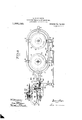
- z - Figures 1', 2 and 3 are diagrammatic views showing Tn difi'erent positions the stabilizer and its gyroscopic pendulums.
- Figs. .4, 5 and 6 are similar views of the same apparatus provided with a special device for counter;
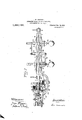
- Fig. 7 is: an elevation partially broken away. of a modification
- 8 is a plan View of the same
- Fig. 9 1s a side elevation ofa submotor hereinafter fully' referred to.
- the stabilizer is constituted by two gyroscopes 1 and 2 having their axes vertical.
- the gyroscope 1 rotates within a frame 3 mounted on trunnions 4, 4 and the gyroscope 2 rotates-in a similar frame 5 mounted, on trunnions 6 6.
- the trunnions 4 4 and 6 6' are arranged in a frame 7 in such a manner.
- the frame 3 has threaded therein a rod 10 along which may slide a counterwejlght or pendulum 11.
- the frame 5 is provi ed with a similar rod 12 having. a pendulum 13. Both pendulums 11 and 13 are of the same weight and dimensions.
- the device which has just been described. possesses great rigidity in the longitudinal direction and the frame 7 has alwaysa tendency to remain horizontal owing .to,
- a force 14 acts to dis lace the frame 7out of its horizontal position and the gyroscopic pendulums 1,
- inertia As to the influence of inertia and via viva they act at the starting of the aeroplane or when its speed varies in flight, and they cause the frame 7 to oscillate as if it were acted upon by a force such as 14, (Fig. 2) or a force in the opposite direction. At the same time thependulums 11 and 13 approach or separate from each other according to the rotation of the gyroscopes and the direction of the force acting on the frame. This property may be employed for compensating for the influence of inertia or m's v'va by means of the following arrange- I ment. One of the trunnions 8 of the frame 7 bears a loose lever 22 (Figs.
- levers are connected by rods 25 and 26 to a lever 27 the trunnion 28 of which may be displaced in a slot 29 of the frame 7
- This trunnion 28 is connected by a rod 30 to a quadrant 31 fixed to a short shaft 32 sup?- ported'by a projection '33 of the frame
- Thesh aft 32 has, at its other end, a bevel pinion 34 which meshes with a pinion 35 on the lever 22.
- the stabilizer be constructed so as to automatically compensate for the eflects-of centrifugal force this device would have no action when the pendulums were displaced in the same direction by said force.
- the gyroscopic pendulums are that the connecting rod 30 receives no motion. If the pendulums were unequally displaced the gyroscopic reaction 011 the frame 7 would be compensated by the unequal action of the levers 23 and 24 of the balance lever 27 and causes a sufiicient displacement of its trunnion 28 to operate the pinion 34.
- a gyroscopic pendulum having a Cardan suspension receives the action of disturbing forces it first offers resistance to any displacement; afterward as the gyroscopic force is annihilated it rapidly inclines itself in a direction perpendicular to the disturbing force, while the frame which is at first under the influence of the gyroscopic inertia modifies its position more slowly and thereafter is displaced to a degree dependent uponthe mass of the gyroscopic pendulum.
- a similar action takes place when the gyroscopic pendulum comes back to its initial position under the influence of gravity, but the two movements produced by gravity and the gyroscopic reaction are never synchronous.
- Figs. 7 and 8 represent by way 'of example a stabilizer provided with such a device.
- a sleeve 37 which bears a helicoidal gear 38 fixed to a current reverscr 39.
- a second sleeve 40 receiving its movement from a pinion and having two contacts 41 which cooperate with the current reverser 39.
- the lever 22 ' At the other end of the sleeve 37 is arranged the lever 22 'whose position must remain invariable whatever the oscillations of the frame 7 may be.
- the lever 22 is provided with a resilient pin 42 which moves against a quadrant 42 having electric contacts 42 connected to a sub-motor which according to the direction of its rotation controls the stabilizing planes of the aeroplane.
- This sub-motor operates in accordance with the position that the sector 42 occupies relatively tothe contact 42 of the lever 22. According as the latter bears on the contact piece .42 or upon the contact piece 42 it sends an electric current into one of the'electromagnets 52 or 53 which attracts an armature 54 which controls a drum 55 keyed upon a shaft 56 which also carries two pimons 57 and 58.
- These pinions which are loosely mounted on the shaft 56 form clutch cones at each end of the drum 55; they rotate with a continuous A when the drum is clutched to one or othermovement but in opposite, directions so that of these pinions by the effect of the induction of one of the magnets, the rotation of the shaft 56 takes-place in one direction-or.
- an arm 63 acts through a rod 64 on the sector 42. to return it to its initial position relatively to the immovable lever 22.
- the helicoidal wheel 38 gears with a screw 43 on the shaft 44 having at its other end a pinion 45 which receives its motion from an electromotor 46 --through gear wheels 47 and 47
- the shaft of the wheel 47 has a sleeve 48 on which are oscillations as this latter.
- scopic pendulums and secondly-that of the combination of these two movements has the effect of correctin' the failure of synchronous deviations. lietween the gyroscopic pendulums and the frame-7, and thuscause the lever 22-to remain motionless in space,
Description
L. MARMONIER.
. AUTOMATIC STABILIZER FOR AEROPLANBS.
APPLICATION FILED OCT. 19, 1911,
Patented Jan. 14, 1913.
5 SHEETS-SHEET 1.
Wibzesses:
fiwajzlar;
M MM
(i waw' L. MARMONIER. AUTOMATIC STABILIZER FOR ABROPLANES. APPLICATION FILED OCT. 19, 1911.
1,050,153. I Patented Jan. 14,1913.
5 SHEETS-SHEET 2.
WiZnesses:
L. MARMONIER. AUTOMATIC STABILIZER FOR AEROPLANES.
APPLIOATION FILED OCT. 19, 1911. 1
' Patented Jan. 14, 1913.
5 SHEET SSHEET 3 L. MARMONIER. AUTOMATIC STABILIZER FOR ABROPLANES. APPLICATION FILED 0OT.19, 1911.
5 SHEETS-SHEET 4.
Patented Jan. 14, 1913.
L. MARMONIER. AUTOMATIC STABILIZER FOR AEROPLANES.
APPLIOATION FILED 001.l9, 1911.
1,050,153. Patented Jami 1,1913,
5 SHEETS-SHEET 5.
Invent I v v mmmgs: 4
Attorne UNITED STATES PATENT onmon."
LOUIS MARMONIER,
or LYON, FRANCE.
AUTOMATIC sranrmznn ron AEROPLANES.
Specification of Letters Patent. Patenfied an, 1441913, Application filed October 19,1911. Serial no. 655,617.
To all-whom it/may concern:
Be it known that I, Loms MARMONIER, a citizen of the French Republic, residing at 37 Rue Servient, Lyon, in France, have invented certain new and useful Improvements in Automatic Stabilizers for Aeroplanes, of-
which the following is a specification.
This invention has for its object an improved stabilizer foraeroplanes in which the property of the gyroscope to give the aeroplane an invariable position in space, whatever may 'be the reactions to which it is subjected,'is utilized. As this property is only effective up to a certain limit beyond which the external forces become suflicient to dis place the gyroscope, it' is necessary to provide in addition to this latter. a Pendulum having a tendency to remain in a vertical plane. This pendulum causes the gyroscope to return to. its normal'position when it has been displaced provided the pendulum has a suflicient mass to overcome the inertia of f the gyroscope itself.
v The employment of a pendulum in a stabilizer for aeroplanes renders it necessary to consider the influence of its Weight v and the action of the forces upon it, in particular' the centrifugal force and the m's m'oa. The reaction of the centrifugal force on the pendular mass of the gyroscope may be compensated by the use of twogyroscopes running in opposite directions, and the disturbances due to m's m'oa and inertia ma be annihilated by the arrangement w ich forms the object of the invention an is hereinafter fully described. I
' In'the annexed drawings z -Figures 1', 2 and 3 are diagrammatic views showing Tn difi'erent positions the stabilizer and its gyroscopic pendulums. Figs. .4, 5 and 6 are similar views of the same apparatus provided with a special device for counter;
balancing the reactions of inertia. Fig. 7 is: an elevation partially broken away. of a modification, 8 isa plan View of the same and Fig. 9 1s a side elevation ofa submotor hereinafter fully' referred to.
The stabilizer is constituted by two gyroscopes 1 and 2 having their axes vertical. The gyroscope 1 rotates within a frame 3 mounted on trunnions 4, 4 and the gyroscope 2 rotates-in a similar frame 5 mounted, on trunnions 6 6. The trunnions 4 4 and 6 6' are arranged in a frame 7 in such a manner.
that their axes are parallel with each other and perpendicular to the trunnions 8 8, around which the frame 7 is capable ofpscillation. The trunnions 8 8 are supported in bearings fixed to the aeroplane by any suitable means and their axis is perpendicular to the direction of the aeroplane which is indicated by the arrow 9. The frame 3 has threaded therein a rod 10 along which may slide a counterwejlght or pendulum 11. The frame 5 is provi ed with a similar rod 12 having. a pendulum 13. Both pendulums 11 and 13 are of the same weight and dimensions. P
Owing to the disposition of the two gyroseopic pendulums in the frames 3 and 5, any
longitudinal movement of 'one'- gyroscope causes the displacement of the other, while both are free in their transverse' displace ments.
In order to obtain the stabilization of aeroplanes it is necessary that the gyroscopes rotate in oppeosite directions and their.
speed and weight equal. The position of the pendulums 11 and 12 on their respective rods must be similar. a 1
. The device which has just been described. possesses great rigidity in the longitudinal direction and the frame 7 has alwaysa tendency to remain horizontal owing .to,
gravity and thereaction of both gyroscopes. If for instance, a force 14 (Fig. 2) acts to dis lace the frame 7out of its horizontal position and the gyroscopic pendulums 1,
1 1 and 2, 13 rotate respectively as indicated by the arrows 15 and 16, the pendulums 11 and lir owing to the reaction of the gyroscopesgo away from each other; if on the direction the pendulums 11 and 13 approach each other. -The' weight of the pendulums other hand the-force 14 acts in the opposite force 14 and retain the frame 7 in the horizontal position. When the aeroplane makes a swerve for'in'stence, in the direction of the arrow (Fig. 3) the gyroscopic pendulums rece1ve{;f?theaction of the centrifugal fiprc'e which tends to bring tli'fem out of the Edive,
in the direction of the arrows- 18 a1id119, giving rise in both gyroscopesv to. a gyro scopic reaction which tends to cause the frame 7 to'oscillate in the direction of the arrow 21 while the gyrosconic pendulums ll,
13 have a tendency to oscillate the frame rium of the frame 7 is not affected and it therefore remains horizontal whatever may be the intensity of the centrifugal force which in consequence acts only to more or less incline the pendulums 11 and 13.
As to the influence of inertia and via viva they act at the starting of the aeroplane or when its speed varies in flight, and they cause the frame 7 to oscillate as if it were acted upon by a force such as 14, (Fig. 2) or a force in the opposite direction. At the same time thependulums 11 and 13 approach or separate from each other according to the rotation of the gyroscopes and the direction of the force acting on the frame. This property may be employed for compensating for the influence of inertia or m's v'va by means of the following arrange- I ment. One of the trunnions 8 of the frame 7 bears a loose lever 22 (Figs. 4, and 6) connected to the frame 7 by a specialarrangement of pivoted connections which compensate for the displacements of said frame by inertia or 02's viva. The trunnions 4 and 6 of the frames 3 and 5 carry levers 23 and 24 parallel to the rods and 12 and respectively upward and downward. These levers are connected by rods 25 and 26 to a lever 27 the trunnion 28 of which may be displaced in a slot 29 of the frame 7 This trunnion 28 is connected by a rod 30 to a quadrant 31 fixed to a short shaft 32 sup?- ported'by a projection '33 of the frame Thesh aft 32 has, at its other end, a bevel pinion 34 which meshes with a pinion 35 on the lever 22. When the gyroscopic pendulums are displaced, for instance as indicated in Fig. 5, the levers 23 and 24 are also displaced and draw in the same direction the balance lever 27 the trunnion of which itself moves along the slot 29. This displacement is transmitted by the rod 30 to the quadrant 31 which causes the shaft 32 to rotate in the direction indicated by the arrow 36 (Fig. 5-). This movement combined with the 0scillation of the projection 33 causes the pinion 34 to take an epicycloidal movement around the pinion 35 which remains motion.- less, as well as the lever 22. It is obvious that this condition may be obtained only when the above mentioned parts are exactly regulated'which however is easy to insure owing to the sliding movements of the levers. When the frame 7 comes back to the horizontal position the parts move in the opposite direction in order to keep the lever motionless. The same device also acts when the frame 7 comes back to its normal osit-ion only by successive oscillations. I the stabilizer be constructed so as to automatically compensate for the eflects-of centrifugal force this device would have no action when the pendulums were displaced in the same direction by said force. In this case (Fig; 6) the gyroscopic pendulums are that the connecting rod 30 receives no motion. If the pendulums were unequally displaced the gyroscopic reaction 011 the frame 7 would be compensated by the unequal action of the levers 23 and 24 of the balance lever 27 and causes a sufiicient displacement of its trunnion 28 to operate the pinion 34.
It is to be noted that when a gyroscopic pendulum having a Cardan suspension receives the action of disturbing forces it first offers resistance to any displacement; afterward as the gyroscopic force is annihilated it rapidly inclines itself in a direction perpendicular to the disturbing force, while the frame which is at first under the influence of the gyroscopic inertia modifies its position more slowly and thereafter is displaced to a degree dependent uponthe mass of the gyroscopic pendulum. A similar action takes place when the gyroscopic pendulum comes back to its initial position under the influence of gravity, but the two movements produced by gravity and the gyroscopic reaction are never synchronous. It is thus necessary to use a supplementary device capable of correcting the backwardness of one of the movements. Figs. 7 and 8 represent by way 'of example a stabilizer provided with such a device. At the end of the trunnion 8 is a sleeve 37 which bears a helicoidal gear 38 fixed to a current reverscr 39. On the sleeve 37 is a second sleeve 40 receiving its movement from a pinion and having two contacts 41 which cooperate with the current reverser 39. At the other end of the sleeve 37 is arranged the lever 22 'whose position must remain invariable whatever the oscillations of the frame 7 may be. The lever 22 is provided with a resilient pin 42 which moves against a quadrant 42 having electric contacts 42 connected to a sub-motor which according to the direction of its rotation controls the stabilizing planes of the aeroplane. This sub-motor operates in accordance with the position that the sector 42 occupies relatively tothe contact 42 of the lever 22. According as the latter bears on the contact piece .42 or upon the contact piece 42 it sends an electric current into one of the'electromagnets 52 or 53 which attracts an armature 54 which controls a drum 55 keyed upon a shaft 56 which also carries two pimons 57 and 58. These pinions which are loosely mounted on the shaft 56 form clutch cones at each end of the drum 55; they rotate with a continuous A when the drum is clutched to one or othermovement but in opposite, directions so that of these pinions by the effect of the induction of one of the magnets, the rotation of the shaft 56 takes-place in one direction-or.
the direction in which the aeroplane'runs,
indicated by the arrow 9, the stabilizing le-,
two brake blocks '49 controlled by a spring 50 and a screw-nut 51. 'The electromotor 46 runs in either direction according to the. po-
sitio-n of the 'contacts4l against'the currentplanes the combination of two gyroscopic The device which has is supported by the projection 33 of the frame and consequently receives the same lever 22 occupies a suitable position. If the equilibrium of the aeroplane is destroyedthe gyroscopic. pendulums are displaced and 3 .act upon the rod then the contacts 41' K as move against the quadrant :39- of the current reservoir and cause the electromotor 46 to rotatein one or the otherdirection at a speed which may -.be controlled .by. the. braking device. 49. {The running .of the "motor also causes the sleeve 37 to rotate and conse-" quently to -displace the current reservoir 39, and the lever 22'. The stabilizing device thus receives two independent .movements,
first that-of the contacts 41 which are controlled by the displacements bf the 4,5-
'.lever 22 the speed of which may eberegulated-by that of the electrornotor 46. The
scopic pendulums, and secondly-that of the combination of these two movements has the effect of correctin' the failure of synchronous deviations. lietween the gyroscopic pendulums and the frame-7, and thuscause the lever 22-to remain motionless in space,
' the electromotor' beginning to' run I slowly and progressively fasterand fasterso as to react on said lever 22 when the oscillations 1 of thefra'me 7 have a tendency to dis lace it.
- What I claim as my invention'an desire just been described to secure by Letters Patentuof the United.
States is e 1. In' an automatic stabilizer for aeroplanes the combination of two gyroscopic pendulums running in opposite directions,
rames supporting said gyroscopic. penduing truylnions which project' at one end out of said second frame, levers on each trunnion connected by rods to a balance lever the axis of which is movablein a slot frame bearing a short shaft,a quadrant at one endof the shaft anda bevel pinion at lums pivoted into another frameand hav-' in said second frame, a projection in said i its other end, a rod connect-ing said quadpendulums running in opposite directions,
frames supporting said. gyroscopic pendulu'nis pivoted into another frame and having trunnions which roject at one end out of said second frame, evers on each trunnion connected by rods to 'a balance lever the jaxi's of which is movable in a slide of said second: frame, a projection. in said frame bearing a short shaft, a quadrantat'one end of the shaft arid a bevel pinion at its other end, a rod connecting said quadrant to the trunnion of the balancelever, a trunnion at each end of the second frame,'a sleeve on one of said trunnions having fixed thereto a lever which remains motionless-1n space, a pinion keyed on said lever and gearln with the pinion on the shortsh'aft and an ,e ectric,
deviceto correct the failure ofsynchronous deviations between the =gyroscop1c pendulums, and the second frame, comprising an 1 electromotor and means to cause said electro motor to run at first slowly and progressively faster and faster when the oscillations of the second frame have a tendency to displace the motionless lever, substantially as described.
In witness whereof I have signed this specification in the presence of two nesses.
Witnesses: y
JEAN GERMAIN, GUILLAUMIE PIOGHE.
j LOUIS MARMONIERQ
Priority Applications (1)
| Application Number | Priority Date | Filing Date | Title |
|---|---|---|---|
| US65561711A US1050153A (en) | 1911-10-19 | 1911-10-19 | Automatic stabilizer for aeroplanes. |
Applications Claiming Priority (1)
| Application Number | Priority Date | Filing Date | Title |
|---|---|---|---|
| US65561711A US1050153A (en) | 1911-10-19 | 1911-10-19 | Automatic stabilizer for aeroplanes. |
Publications (1)
| Publication Number | Publication Date |
|---|---|
| US1050153A true US1050153A (en) | 1913-01-14 |
Family
ID=3118420
Family Applications (1)
| Application Number | Title | Priority Date | Filing Date |
|---|---|---|---|
| US65561711A Expired - Lifetime US1050153A (en) | 1911-10-19 | 1911-10-19 | Automatic stabilizer for aeroplanes. |
Country Status (1)
| Country | Link |
|---|---|
| US (1) | US1050153A (en) |
Cited By (9)
| Publication number | Priority date | Publication date | Assignee | Title |
|---|---|---|---|---|
| US2539772A (en) * | 1945-10-20 | 1951-01-30 | Raytheon Mfg Co | Position stabilizing device |
| US2566305A (en) * | 1947-01-08 | 1951-09-04 | Harold R Beacom | System for eliminating or greatly reducing the errors in gyroscopic devices or the like |
| US2845800A (en) * | 1953-03-23 | 1958-08-05 | Jr Lawrence Holmes | Gyroscope unit and interlocking means |
| US3439548A (en) * | 1966-01-28 | 1969-04-22 | Tibor Horvath | Torque generator |
| US3742770A (en) * | 1971-02-10 | 1973-07-03 | Kaman Aerospace Corp | Gyroscopic stabilizer |
| US3784363A (en) * | 1971-04-28 | 1974-01-08 | Kaman Aerospace Corp | Damped gyroscopic stabilizer |
| US4399714A (en) * | 1981-11-09 | 1983-08-23 | Navidyne Corporation | Method and apparatus for overcoming certain destabilizing torques on gyro-stabilized platforms |
| US20080302194A1 (en) * | 2005-08-22 | 2008-12-11 | Anthony Richard Elms | Stabilising Means |
| WO2014207263A1 (en) * | 2013-06-25 | 2014-12-31 | In-Nova, Programa De Innovación Internacional, S.L. | Gyroscopic torque generator and assembly for measuring dynamic torque |
-
1911
- 1911-10-19 US US65561711A patent/US1050153A/en not_active Expired - Lifetime
Cited By (10)
| Publication number | Priority date | Publication date | Assignee | Title |
|---|---|---|---|---|
| US2539772A (en) * | 1945-10-20 | 1951-01-30 | Raytheon Mfg Co | Position stabilizing device |
| US2566305A (en) * | 1947-01-08 | 1951-09-04 | Harold R Beacom | System for eliminating or greatly reducing the errors in gyroscopic devices or the like |
| US2845800A (en) * | 1953-03-23 | 1958-08-05 | Jr Lawrence Holmes | Gyroscope unit and interlocking means |
| US3439548A (en) * | 1966-01-28 | 1969-04-22 | Tibor Horvath | Torque generator |
| US3742770A (en) * | 1971-02-10 | 1973-07-03 | Kaman Aerospace Corp | Gyroscopic stabilizer |
| US3784363A (en) * | 1971-04-28 | 1974-01-08 | Kaman Aerospace Corp | Damped gyroscopic stabilizer |
| US4399714A (en) * | 1981-11-09 | 1983-08-23 | Navidyne Corporation | Method and apparatus for overcoming certain destabilizing torques on gyro-stabilized platforms |
| US20080302194A1 (en) * | 2005-08-22 | 2008-12-11 | Anthony Richard Elms | Stabilising Means |
| US8555734B2 (en) * | 2005-08-22 | 2013-10-15 | Technology Investment Company Pty Ltd | Stabilising means |
| WO2014207263A1 (en) * | 2013-06-25 | 2014-12-31 | In-Nova, Programa De Innovación Internacional, S.L. | Gyroscopic torque generator and assembly for measuring dynamic torque |
Similar Documents
| Publication | Publication Date | Title |
|---|---|---|
| US1050153A (en) | Automatic stabilizer for aeroplanes. | |
| US2970480A (en) | Anti-friction support mechanism for gyroscopic devices | |
| US1930082A (en) | Gyroscopic compass | |
| US1947562A (en) | Stabilizing and directing gyroscopic control mechanism | |
| US1324477A (en) | l tanner | |
| US1186856A (en) | Gyroscopic apparatus. | |
| US2427158A (en) | Vertical-seeking gyro | |
| US2041526A (en) | Gyro baseline | |
| US1645079A (en) | Stabilizer | |
| US1940387A (en) | Gyroscopic pendulum | |
| US1801947A (en) | Apparatus for the diagonal control of moving objects, particularly aeroplanes | |
| US1446348A (en) | Gyroscope | |
| US2366995A (en) | Stabilizing arrangement for control pendulums | |
| US1923885A (en) | Gyroscopic compass | |
| US1642087A (en) | Direction indicator for moving bodies | |
| US1518762A (en) | Gyroscopic compass | |
| US1545812A (en) | Gyroscopic equilibrator | |
| US1368226A (en) | Aeroplane-stabilizer | |
| US1935740A (en) | Aeroplane instrument | |
| US2643547A (en) | Gyroscope having erecting means to compensate for acceleration errors | |
| US1880994A (en) | Indicator for aircraft | |
| US2685207A (en) | Compensated gyro vertical | |
| US1309409A (en) | henderson | |
| US2323151A (en) | Automatic steering control for aircraft | |
| US2758478A (en) | Fieux |