US10500840B2 - Printing apparatus and control method that control movement of a transfer member - Google Patents
Printing apparatus and control method that control movement of a transfer member Download PDFInfo
- Publication number
- US10500840B2 US10500840B2 US15/925,856 US201815925856A US10500840B2 US 10500840 B2 US10500840 B2 US 10500840B2 US 201815925856 A US201815925856 A US 201815925856A US 10500840 B2 US10500840 B2 US 10500840B2
- Authority
- US
- United States
- Prior art keywords
- image
- unit
- transfer member
- transfer
- Prior art date
- Legal status (The legal status is an assumption and is not a legal conclusion. Google has not performed a legal analysis and makes no representation as to the accuracy of the status listed.)
- Expired - Fee Related
Links
- 238000012546 transfer Methods 0.000 title claims abstract description 272
- 238000007639 printing Methods 0.000 title claims abstract description 140
- 238000000034 method Methods 0.000 title claims abstract description 63
- 238000012545 processing Methods 0.000 claims abstract description 187
- 230000008569 process Effects 0.000 claims abstract description 33
- 230000015572 biosynthetic process Effects 0.000 claims description 24
- 238000004148 unit process Methods 0.000 claims description 4
- 239000000976 ink Substances 0.000 description 154
- 239000007788 liquid Substances 0.000 description 37
- 230000007246 mechanism Effects 0.000 description 31
- 238000011084 recovery Methods 0.000 description 24
- 239000000463 material Substances 0.000 description 23
- 230000002093 peripheral effect Effects 0.000 description 22
- 239000010410 layer Substances 0.000 description 20
- 238000004891 communication Methods 0.000 description 19
- 238000007689 inspection Methods 0.000 description 19
- 238000010438 heat treatment Methods 0.000 description 15
- 230000005540 biological transmission Effects 0.000 description 13
- 238000004140 cleaning Methods 0.000 description 13
- 238000003860 storage Methods 0.000 description 11
- 238000010521 absorption reaction Methods 0.000 description 10
- 229920005989 resin Polymers 0.000 description 10
- 239000011347 resin Substances 0.000 description 10
- 229910019250 POS3 Inorganic materials 0.000 description 8
- 238000004040 coloring Methods 0.000 description 8
- 238000001816 cooling Methods 0.000 description 8
- 230000003247 decreasing effect Effects 0.000 description 8
- 230000006870 function Effects 0.000 description 8
- 230000015654 memory Effects 0.000 description 8
- 238000003708 edge detection Methods 0.000 description 7
- 229920001971 elastomer Polymers 0.000 description 7
- 238000012805 post-processing Methods 0.000 description 7
- 239000002344 surface layer Substances 0.000 description 7
- 230000008859 change Effects 0.000 description 6
- 239000005060 rubber Substances 0.000 description 6
- 238000010586 diagram Methods 0.000 description 5
- 230000007423 decrease Effects 0.000 description 4
- 239000011148 porous material Substances 0.000 description 4
- 230000004044 response Effects 0.000 description 4
- 230000002441 reversible effect Effects 0.000 description 4
- 229920002379 silicone rubber Polymers 0.000 description 4
- XLYOFNOQVPJJNP-UHFFFAOYSA-N water Substances O XLYOFNOQVPJJNP-UHFFFAOYSA-N 0.000 description 4
- 229920000459 Nitrile rubber Polymers 0.000 description 3
- MHABMANUFPZXEB-UHFFFAOYSA-N O-demethyl-aloesaponarin I Natural products O=C1C2=CC=CC(O)=C2C(=O)C2=C1C=C(O)C(C(O)=O)=C2C MHABMANUFPZXEB-UHFFFAOYSA-N 0.000 description 3
- 238000009835 boiling Methods 0.000 description 3
- 239000011248 coating agent Substances 0.000 description 3
- 238000000576 coating method Methods 0.000 description 3
- 239000000470 constituent Substances 0.000 description 3
- 238000002156 mixing Methods 0.000 description 3
- 230000002035 prolonged effect Effects 0.000 description 3
- 239000007787 solid Substances 0.000 description 3
- IJGRMHOSHXDMSA-UHFFFAOYSA-N Atomic nitrogen Chemical compound N#N IJGRMHOSHXDMSA-UHFFFAOYSA-N 0.000 description 2
- KAKZBPTYRLMSJV-UHFFFAOYSA-N Butadiene Chemical compound C=CC=C KAKZBPTYRLMSJV-UHFFFAOYSA-N 0.000 description 2
- PPBRXRYQALVLMV-UHFFFAOYSA-N Styrene Chemical compound C=CC1=CC=CC=C1 PPBRXRYQALVLMV-UHFFFAOYSA-N 0.000 description 2
- 229920006311 Urethane elastomer Polymers 0.000 description 2
- 230000004913 activation Effects 0.000 description 2
- 239000000919 ceramic Substances 0.000 description 2
- 230000006835 compression Effects 0.000 description 2
- 238000007906 compression Methods 0.000 description 2
- 238000006073 displacement reaction Methods 0.000 description 2
- 229920005560 fluorosilicone rubber Polymers 0.000 description 2
- 238000012423 maintenance Methods 0.000 description 2
- 239000000155 melt Substances 0.000 description 2
- XJWOWXZSFTXJEX-UHFFFAOYSA-N phenylsilicon Chemical compound [Si]C1=CC=CC=C1 XJWOWXZSFTXJEX-UHFFFAOYSA-N 0.000 description 2
- 239000000049 pigment Substances 0.000 description 2
- 229920001084 poly(chloroprene) Polymers 0.000 description 2
- 239000004945 silicone rubber Substances 0.000 description 2
- 238000004381 surface treatment Methods 0.000 description 2
- 238000012360 testing method Methods 0.000 description 2
- 238000011144 upstream manufacturing Methods 0.000 description 2
- 239000004925 Acrylic resin Substances 0.000 description 1
- 229920000178 Acrylic resin Polymers 0.000 description 1
- 229920000181 Ethylene propylene rubber Polymers 0.000 description 1
- KRHYYFGTRYWZRS-UHFFFAOYSA-M Fluoride anion Chemical compound [F-] KRHYYFGTRYWZRS-UHFFFAOYSA-M 0.000 description 1
- YCKRFDGAMUMZLT-UHFFFAOYSA-N Fluorine atom Chemical compound [F] YCKRFDGAMUMZLT-UHFFFAOYSA-N 0.000 description 1
- 244000043261 Hevea brasiliensis Species 0.000 description 1
- 101000911772 Homo sapiens Hsc70-interacting protein Proteins 0.000 description 1
- 101001139126 Homo sapiens Krueppel-like factor 6 Proteins 0.000 description 1
- CBENFWSGALASAD-UHFFFAOYSA-N Ozone Chemical compound [O-][O+]=O CBENFWSGALASAD-UHFFFAOYSA-N 0.000 description 1
- 239000005062 Polybutadiene Substances 0.000 description 1
- BLRPTPMANUNPDV-UHFFFAOYSA-N Silane Chemical compound [SiH4] BLRPTPMANUNPDV-UHFFFAOYSA-N 0.000 description 1
- 238000009825 accumulation Methods 0.000 description 1
- NIXOWILDQLNWCW-UHFFFAOYSA-N acrylic acid group Chemical group C(C=C)(=O)O NIXOWILDQLNWCW-UHFFFAOYSA-N 0.000 description 1
- 229920000800 acrylic rubber Polymers 0.000 description 1
- 239000000853 adhesive Substances 0.000 description 1
- 230000001070 adhesive effect Effects 0.000 description 1
- 239000002390 adhesive tape Substances 0.000 description 1
- 230000008901 benefit Effects 0.000 description 1
- 230000000740 bleeding effect Effects 0.000 description 1
- 238000007664 blowing Methods 0.000 description 1
- 239000003795 chemical substances by application Substances 0.000 description 1
- 239000000701 coagulant Substances 0.000 description 1
- 230000001112 coagulating effect Effects 0.000 description 1
- 230000015271 coagulation Effects 0.000 description 1
- 238000005345 coagulation Methods 0.000 description 1
- 230000000295 complement effect Effects 0.000 description 1
- 229920001577 copolymer Polymers 0.000 description 1
- 238000003851 corona treatment Methods 0.000 description 1
- 238000012937 correction Methods 0.000 description 1
- 230000008878 coupling Effects 0.000 description 1
- 238000010168 coupling process Methods 0.000 description 1
- 238000005859 coupling reaction Methods 0.000 description 1
- 238000005520 cutting process Methods 0.000 description 1
- 230000003111 delayed effect Effects 0.000 description 1
- 238000013461 design Methods 0.000 description 1
- 238000001514 detection method Methods 0.000 description 1
- 238000007607 die coating method Methods 0.000 description 1
- 238000007599 discharging Methods 0.000 description 1
- 238000001035 drying Methods 0.000 description 1
- 239000000428 dust Substances 0.000 description 1
- 239000000806 elastomer Substances 0.000 description 1
- 230000005611 electricity Effects 0.000 description 1
- HQQADJVZYDDRJT-UHFFFAOYSA-N ethene;prop-1-ene Chemical group C=C.CC=C HQQADJVZYDDRJT-UHFFFAOYSA-N 0.000 description 1
- 239000004744 fabric Substances 0.000 description 1
- 238000012840 feeding operation Methods 0.000 description 1
- 239000000945 filler Substances 0.000 description 1
- 239000010419 fine particle Substances 0.000 description 1
- 239000012530 fluid Substances 0.000 description 1
- 239000011737 fluorine Substances 0.000 description 1
- 229910052731 fluorine Inorganic materials 0.000 description 1
- 239000004088 foaming agent Substances 0.000 description 1
- 230000014509 gene expression Effects 0.000 description 1
- 238000003384 imaging method Methods 0.000 description 1
- 229920003049 isoprene rubber Polymers 0.000 description 1
- 238000003475 lamination Methods 0.000 description 1
- QSHDDOUJBYECFT-UHFFFAOYSA-N mercury Chemical compound [Hg] QSHDDOUJBYECFT-UHFFFAOYSA-N 0.000 description 1
- 229910052753 mercury Inorganic materials 0.000 description 1
- 229910021645 metal ion Inorganic materials 0.000 description 1
- 229910044991 metal oxide Inorganic materials 0.000 description 1
- 150000004706 metal oxides Chemical class 0.000 description 1
- 238000012986 modification Methods 0.000 description 1
- 230000004048 modification Effects 0.000 description 1
- 229920003052 natural elastomer Polymers 0.000 description 1
- 229920001194 natural rubber Polymers 0.000 description 1
- 229910052757 nitrogen Inorganic materials 0.000 description 1
- 230000003287 optical effect Effects 0.000 description 1
- 150000007524 organic acids Chemical class 0.000 description 1
- 239000003960 organic solvent Substances 0.000 description 1
- 150000003961 organosilicon compounds Chemical class 0.000 description 1
- 238000009832 plasma treatment Methods 0.000 description 1
- 239000002985 plastic film Substances 0.000 description 1
- 229920006255 plastic film Polymers 0.000 description 1
- 238000005498 polishing Methods 0.000 description 1
- 229920000058 polyacrylate Polymers 0.000 description 1
- 229920002857 polybutadiene Polymers 0.000 description 1
- 238000007781 pre-processing Methods 0.000 description 1
- 208000002343 primary orthostatic tremor Diseases 0.000 description 1
- 230000001737 promoting effect Effects 0.000 description 1
- 150000003839 salts Chemical class 0.000 description 1
- 238000007790 scraping Methods 0.000 description 1
- 238000006748 scratching Methods 0.000 description 1
- 230000002393 scratching effect Effects 0.000 description 1
- 239000004065 semiconductor Substances 0.000 description 1
- 229910000077 silane Inorganic materials 0.000 description 1
- 229920002050 silicone resin Polymers 0.000 description 1
- 239000002356 single layer Substances 0.000 description 1
- 239000002904 solvent Substances 0.000 description 1
- 238000001179 sorption measurement Methods 0.000 description 1
- 230000003068 static effect Effects 0.000 description 1
- 239000000126 substance Substances 0.000 description 1
- 239000004094 surface-active agent Substances 0.000 description 1
- 230000016776 visual perception Effects 0.000 description 1
- 238000003466 welding Methods 0.000 description 1
- 230000003936 working memory Effects 0.000 description 1
- 239000002759 woven fabric Substances 0.000 description 1
Images


Classifications
-
- B—PERFORMING OPERATIONS; TRANSPORTING
- B41—PRINTING; LINING MACHINES; TYPEWRITERS; STAMPS
- B41J—TYPEWRITERS; SELECTIVE PRINTING MECHANISMS, i.e. MECHANISMS PRINTING OTHERWISE THAN FROM A FORME; CORRECTION OF TYPOGRAPHICAL ERRORS
- B41J2/00—Typewriters or selective printing mechanisms characterised by the printing or marking process for which they are designed
- B41J2/005—Typewriters or selective printing mechanisms characterised by the printing or marking process for which they are designed characterised by bringing liquid or particles selectively into contact with a printing material
- B41J2/0057—Typewriters or selective printing mechanisms characterised by the printing or marking process for which they are designed characterised by bringing liquid or particles selectively into contact with a printing material where an intermediate transfer member receives the ink before transferring it on the printing material
-
- B—PERFORMING OPERATIONS; TRANSPORTING
- B41—PRINTING; LINING MACHINES; TYPEWRITERS; STAMPS
- B41J—TYPEWRITERS; SELECTIVE PRINTING MECHANISMS, i.e. MECHANISMS PRINTING OTHERWISE THAN FROM A FORME; CORRECTION OF TYPOGRAPHICAL ERRORS
- B41J2/00—Typewriters or selective printing mechanisms characterised by the printing or marking process for which they are designed
- B41J2/005—Typewriters or selective printing mechanisms characterised by the printing or marking process for which they are designed characterised by bringing liquid or particles selectively into contact with a printing material
- B41J2/01—Ink jet
-
- B—PERFORMING OPERATIONS; TRANSPORTING
- B41—PRINTING; LINING MACHINES; TYPEWRITERS; STAMPS
- B41J—TYPEWRITERS; SELECTIVE PRINTING MECHANISMS, i.e. MECHANISMS PRINTING OTHERWISE THAN FROM A FORME; CORRECTION OF TYPOGRAPHICAL ERRORS
- B41J11/00—Devices or arrangements of selective printing mechanisms, e.g. ink-jet printers or thermal printers, for supporting or handling copy material in sheet or web form
- B41J11/66—Applications of cutting devices
- B41J11/663—Controlling cutting, cutting resulting in special shapes of the cutting line, e.g. controlling cutting positions, e.g. for cutting in the immediate vicinity of a printed image
-
- B—PERFORMING OPERATIONS; TRANSPORTING
- B41—PRINTING; LINING MACHINES; TYPEWRITERS; STAMPS
- B41J—TYPEWRITERS; SELECTIVE PRINTING MECHANISMS, i.e. MECHANISMS PRINTING OTHERWISE THAN FROM A FORME; CORRECTION OF TYPOGRAPHICAL ERRORS
- B41J13/00—Devices or arrangements of selective printing mechanisms, e.g. ink-jet printers or thermal printers, specially adapted for supporting or handling copy material in short lengths, e.g. sheets
- B41J13/0009—Devices or arrangements of selective printing mechanisms, e.g. ink-jet printers or thermal printers, specially adapted for supporting or handling copy material in short lengths, e.g. sheets control of the transport of the copy material
- B41J13/0018—Devices or arrangements of selective printing mechanisms, e.g. ink-jet printers or thermal printers, specially adapted for supporting or handling copy material in short lengths, e.g. sheets control of the transport of the copy material in the sheet input section of automatic paper handling systems
-
- B—PERFORMING OPERATIONS; TRANSPORTING
- B41—PRINTING; LINING MACHINES; TYPEWRITERS; STAMPS
- B41J—TYPEWRITERS; SELECTIVE PRINTING MECHANISMS, i.e. MECHANISMS PRINTING OTHERWISE THAN FROM A FORME; CORRECTION OF TYPOGRAPHICAL ERRORS
- B41J13/00—Devices or arrangements of selective printing mechanisms, e.g. ink-jet printers or thermal printers, specially adapted for supporting or handling copy material in short lengths, e.g. sheets
- B41J13/10—Sheet holders, retainers, movable guides, or stationary guides
- B41J13/103—Sheet holders, retainers, movable guides, or stationary guides for the sheet feeding section
-
- B—PERFORMING OPERATIONS; TRANSPORTING
- B41—PRINTING; LINING MACHINES; TYPEWRITERS; STAMPS
- B41J—TYPEWRITERS; SELECTIVE PRINTING MECHANISMS, i.e. MECHANISMS PRINTING OTHERWISE THAN FROM A FORME; CORRECTION OF TYPOGRAPHICAL ERRORS
- B41J2/00—Typewriters or selective printing mechanisms characterised by the printing or marking process for which they are designed
- B41J2/005—Typewriters or selective printing mechanisms characterised by the printing or marking process for which they are designed characterised by bringing liquid or particles selectively into contact with a printing material
- B41J2/01—Ink jet
- B41J2/015—Ink jet characterised by the jet generation process
- B41J2/02—Ink jet characterised by the jet generation process generating a continuous ink jet
- B41J2/03—Ink jet characterised by the jet generation process generating a continuous ink jet by pressure
-
- B—PERFORMING OPERATIONS; TRANSPORTING
- B41—PRINTING; LINING MACHINES; TYPEWRITERS; STAMPS
- B41J—TYPEWRITERS; SELECTIVE PRINTING MECHANISMS, i.e. MECHANISMS PRINTING OTHERWISE THAN FROM A FORME; CORRECTION OF TYPOGRAPHICAL ERRORS
- B41J2/00—Typewriters or selective printing mechanisms characterised by the printing or marking process for which they are designed
- B41J2/005—Typewriters or selective printing mechanisms characterised by the printing or marking process for which they are designed characterised by bringing liquid or particles selectively into contact with a printing material
- B41J2/01—Ink jet
- B41J2/07—Ink jet characterised by jet control
- B41J2/125—Sensors, e.g. deflection sensors
-
- B—PERFORMING OPERATIONS; TRANSPORTING
- B41—PRINTING; LINING MACHINES; TYPEWRITERS; STAMPS
- B41J—TYPEWRITERS; SELECTIVE PRINTING MECHANISMS, i.e. MECHANISMS PRINTING OTHERWISE THAN FROM A FORME; CORRECTION OF TYPOGRAPHICAL ERRORS
- B41J2/00—Typewriters or selective printing mechanisms characterised by the printing or marking process for which they are designed
- B41J2/005—Typewriters or selective printing mechanisms characterised by the printing or marking process for which they are designed characterised by bringing liquid or particles selectively into contact with a printing material
- B41J2/01—Ink jet
- B41J2/135—Nozzles
- B41J2/14—Structure thereof only for on-demand ink jet heads
- B41J2/14016—Structure of bubble jet print heads
- B41J2/14024—Assembling head parts
-
- B—PERFORMING OPERATIONS; TRANSPORTING
- B41—PRINTING; LINING MACHINES; TYPEWRITERS; STAMPS
- B41J—TYPEWRITERS; SELECTIVE PRINTING MECHANISMS, i.e. MECHANISMS PRINTING OTHERWISE THAN FROM A FORME; CORRECTION OF TYPOGRAPHICAL ERRORS
- B41J2/00—Typewriters or selective printing mechanisms characterised by the printing or marking process for which they are designed
- B41J2/005—Typewriters or selective printing mechanisms characterised by the printing or marking process for which they are designed characterised by bringing liquid or particles selectively into contact with a printing material
- B41J2/01—Ink jet
- B41J2/135—Nozzles
- B41J2/145—Arrangement thereof
- B41J2/155—Arrangement thereof for line printing
-
- B—PERFORMING OPERATIONS; TRANSPORTING
- B41—PRINTING; LINING MACHINES; TYPEWRITERS; STAMPS
- B41J—TYPEWRITERS; SELECTIVE PRINTING MECHANISMS, i.e. MECHANISMS PRINTING OTHERWISE THAN FROM A FORME; CORRECTION OF TYPOGRAPHICAL ERRORS
- B41J2/00—Typewriters or selective printing mechanisms characterised by the printing or marking process for which they are designed
- B41J2/005—Typewriters or selective printing mechanisms characterised by the printing or marking process for which they are designed characterised by bringing liquid or particles selectively into contact with a printing material
- B41J2/01—Ink jet
- B41J2/21—Ink jet for multi-colour printing
- B41J2/2107—Ink jet for multi-colour printing characterised by the ink properties
- B41J2/211—Mixing of inks, solvent or air prior to paper contact
-
- G—PHYSICS
- G06—COMPUTING; CALCULATING OR COUNTING
- G06K—GRAPHICAL DATA READING; PRESENTATION OF DATA; RECORD CARRIERS; HANDLING RECORD CARRIERS
- G06K15/00—Arrangements for producing a permanent visual presentation of the output data, e.g. computer output printers
- G06K15/02—Arrangements for producing a permanent visual presentation of the output data, e.g. computer output printers using printers
- G06K15/18—Conditioning data for presenting it to the physical printing elements
- G06K15/1801—Input data handling means
-
- B—PERFORMING OPERATIONS; TRANSPORTING
- B41—PRINTING; LINING MACHINES; TYPEWRITERS; STAMPS
- B41J—TYPEWRITERS; SELECTIVE PRINTING MECHANISMS, i.e. MECHANISMS PRINTING OTHERWISE THAN FROM A FORME; CORRECTION OF TYPOGRAPHICAL ERRORS
- B41J2/00—Typewriters or selective printing mechanisms characterised by the printing or marking process for which they are designed
- B41J2/005—Typewriters or selective printing mechanisms characterised by the printing or marking process for which they are designed characterised by bringing liquid or particles selectively into contact with a printing material
- B41J2/01—Ink jet
- B41J2002/012—Ink jet with intermediate transfer member
Definitions
- the present invention relates to a technique of transferring an ink image to a print medium.
- various processes for forming an image to be transferred are performed (see Japanese Patent Laid-Open No. 2005-153187).
- the processing time of these processes increases in proportion to the size of a processed image. For example, with respect to images of the same paper size, the amount of data to be processed for an image of 1,200 dots per inch (dpi) is four times greater than that for an image of 600 dpi. Thus, the processing time can increase up to about four times.
- Some processing apparatuses can complete, for an image having a resolution equal to or less than a predetermined value, such as 600 dpi, the above-described processes within a predetermined period related to processing of transferring an image to a print medium but may not be able to complete the processes within the predetermined period for an image having a resolution exceeding the predetermined value. In this case, control of a mechanism of transferring an image to a print medium may become complicated.
- a predetermined value such as 600 dpi
- the present invention provides a system that simply and appropriately transfers an image to a print medium in accordance with the capability of an apparatus for processing print target data.
- the present invention provides a printing apparatus comprising a transfer member configured to move to cyclically pass through a formation area of an ink image and a transfer area in which the ink image is transferred to a cut sheet, a supply unit configured to supply the cut sheet to the transfer member continuously, a data acquisition unit configured to acquire print data for forming the ink image on the transfer member, that is obtained when an image processing unit processes data representing an image of a print target, a print unit configured to discharge ink to the transfer member based on the print data and form the ink image on the transfer member in the formation area of the ink image, and a transfer unit configured to transfer the ink image from the transfer member to the cut sheet supplied by the supply unit in the transfer area, wherein the transfer member is provided so as to be capable of holding images of a plurality of cut sheets in a direction in which the transfer member passes through the formation area of the ink image, and the printing apparatus further comprises a control unit configured to control, when continuously printing on the plurality of cut sheets of the same size, the
- FIG. 1 is a schematic view showing a printing system.
- FIG. 2 is a perspective view showing a print unit.
- FIG. 3 is an explanatory view showing a displacement mode of the print unit in FIG. 2 .
- FIG. 4 is a block diagram showing a control system of the printing system in FIG. 1 .
- FIG. 5 is a block diagram showing the control system of the printing system in FIG. 1 .
- FIG. 6 is an explanatory view showing an example of the operation of the printing system in FIG. 1 .
- FIG. 7 is an explanatory view showing an example of the operation of the printing system in FIG. 1 .
- FIG. 8 is a block diagram showing an example of the arrangement of a printing control unit.
- FIG. 9 is a block diagram showing an example of a functional arrangement implemented in the printing control unit.
- FIG. 10 is a table showing an example of the structure of a print order table.
- FIG. 11 is a table showing an example of the structure of a print order table according to an embodiment.
- FIG. 12 is a table showing another example of the structure of the print order table according to the embodiment.
- FIG. 13 is a view showing an example of the structure of information included in the print order table.
- FIG. 14 is a flowchart illustrating an example of a processing sequence executed by the printing system.
- FIG. 15 is a view showing an example of processing executed by the printing system.
- FIG. 16 is a view showing signals for paper feed stop control.
- FIGS. 17A and 17B are views showing another example of the processing executed by the printing system.
- arrows X and Y indicate horizontal directions perpendicular to each other.
- An arrow Z indicates a vertical direction.
- FIG. 1 is a front view schematically showing a printing system 1 according to an embodiment of the present invention.
- the printing system 1 is a sheet inkjet printer that forms a printed product P′ by transferring an ink image to a print medium P via a transfer member 2 .
- the printing system 1 includes a printing apparatus 1 A and a conveyance apparatus 1 B.
- an X direction, a Y direction, and a Z direction indicate the widthwise direction (total length direction), the depth direction, and the height direction of the printing system 1 , respectively.
- the print medium P is conveyed in the X direction.
- print includes not only formation of significant information, such as a character or a graphic pattern, but also formation of an image, design, or pattern on a print medium in a broader sense, or processing of a print medium regardless of whether the information is significant or insignificant or has become obvious to allow human visual perception.
- a “print medium” is assumed to be a paper sheet, but may be a fabric, plastic film, or the like.
- An ink component is not particularly limited. In this embodiment, however, a case is assumed in which water-soluble pigment ink that includes a pigment as a coloring material, water, and a resin is used.
- the printing apparatus 1 A includes a print unit 3 , a transfer unit 4 , peripheral units 5 A to 5 D, and a supply unit 6 .
- the print unit 3 includes a plurality of printheads 30 and a carriage 31 . A description will be made with reference to FIGS. 1 and 2 .
- FIG. 2 is a perspective view showing the print unit 3 .
- the printheads 30 discharge liquid ink to the transfer member 2 and form ink images of a printed image on the transfer member 2 .
- each printhead 30 is a full-line head elongated in the Y direction, and nozzles are arrayed in a range in which they cover the width of an image printing area of a print medium having a usable maximum size.
- Each printhead 30 has an ink discharge surface with the opened nozzle on its lower surface, and the ink discharge surface faces the surface of the transfer member 2 via a minute gap (for example, several mm).
- the transfer member 2 is configured to move on a circular orbit cyclically, and thus, the plurality of printheads 30 are arranged radially.
- Each nozzle includes a discharge element.
- the discharge element is, for example, an element that generates a pressure in the nozzle and discharges ink in the nozzle, and the technique of an inkjet head in a known inkjet printer is applicable.
- an element that discharges ink by causing film boiling in ink with an electrothermal transducer and forming a bubble, an element that discharges ink by an electromechanical transducer, an element that discharges ink by using static electricity, or the like can be used as the discharge element.
- a discharge element that uses the electrothermal transducer can be used from the viewpoint of high-speed and high-density printing.
- nine printheads 30 are provided.
- the respective printheads 30 discharge different kinds of inks.
- the different kinds of inks are, for example, different in coloring material and include yellow ink, magenta ink, cyan ink, black ink, and the like.
- One printhead 30 discharges one kind of ink.
- One printhead 30 may, however, be configured to discharge the plurality of kinds of inks. When the plurality of printheads 30 are thus provided, some of them may discharge ink (for example, clear ink) that does not include a coloring material.
- the carriage 31 supports the plurality of printheads 30 .
- the end of each printhead 30 on the side of an ink discharge surface is fixed to the carriage 31 . This makes it possible to maintain a gap on the surface between the ink discharge surface and the transfer member 2 more precisely.
- the carriage 31 is configured to be displaceable while mounting the printheads 30 by the guide of each guide member RL.
- the guide members RL are rail members elongated in the Y direction and provided as a pair separately in the X direction.
- a slide portion 32 is provided on each side of the carriage 31 in the X direction. The slide portions 32 engage with the guide members RL and slide along the guide members RL in the Y direction.
- FIG. 3 is a view showing a displacement mode of the print unit 3 and schematically showing the right side surface of the printing system 1 .
- a recovery unit 12 is provided in the rear of the printing system 1 .
- the recovery unit 12 has a function of recovering discharge performance of the printheads 30 .
- a cap mechanism that caps the ink discharge surface of each printhead 30
- a wiper mechanism that wipes the ink discharge surface
- a suction mechanism that sucks ink in the printhead 30 by a negative pressure from the ink discharge surface can be given as such mechanisms.
- the guide member RL is elongated over the recovery unit 12 from the side of the transfer member 2 .
- the print unit 3 is displaceable between a discharge position POS 1 , at which the print unit 3 is indicated by a solid line, and a recovery position POS 3 , at which the print unit 3 is indicated by a broken line, and is moved by a driving mechanism (not shown).
- the discharge position POS 1 is a position at which the print unit 3 discharges ink to the transfer member 2 and a position at which the ink discharge surface of each printhead 30 faces the surface of the transfer member 2 .
- the recovery position POS 3 is a position retracted from the discharge position POS 1 and a position at which the print unit 3 is positioned above the recovery unit 12 .
- the recovery unit 12 can perform recovery processing on the printheads 30 when the print unit 3 is positioned at the recovery position POS 3 . In this embodiment, the recovery unit 12 can also perform the recovery processing in the middle of movement before the print unit 3 reaches the recovery position POS 3 .
- the recovery unit 12 can perform preliminary recovery processing on the printheads 30 at the preliminary recovery position POS 2 while the printheads 30 move from the discharge position POS 1 to the recovery position POS 3 .
- the transfer unit 4 will be described with reference to FIG. 1 .
- the transfer unit 4 includes a transfer drum 41 and a pressurizing drum 42 .
- Each of these drums is a rotating member that rotates about a rotation axis in the Y direction and has a cylindrical outer peripheral surface.
- arrows shown in respective views of the transfer drum 41 and the pressurizing drum 42 indicate their rotation directions.
- the transfer drum 41 rotates clockwise, and the pressurizing drum 42 rotates anticlockwise.
- the transfer drum 41 is a support member that supports the transfer member 2 on its outer peripheral surface.
- the transfer member 2 is provided on the outer peripheral surface of the transfer drum 41 continuously or intermittently in a circumferential direction. If the transfer member 2 is provided continuously, it is formed into an endless swath. If the transfer member 2 is provided intermittently, it is formed into swaths with ends dividedly into a plurality of segments. The respective segments can be arranged in an arc at an equal pitch on the outer peripheral surface of the transfer drum 41 .
- the transfer member 2 moves cyclically on the circular orbit by rotating the transfer drum 41 .
- the position of the transfer member 2 can be discriminated into a processing area R 1 before discharge, a discharge area R 2 , processing areas R 3 and R 4 after discharge, a transfer area R 5 , and a processing area R 6 after transfer.
- the transfer member 2 passes through these areas cyclically.
- the processing area R 1 before discharge is an area in which preprocessing is performed on the transfer member 2 before the print unit 3 discharges ink and an area in which the peripheral unit 5 A performs processing.
- a reactive liquid is applied.
- the discharge area R 2 is a formation area in which the print unit 3 forms an ink image by discharging ink to the transfer member 2 .
- the processing areas R 3 and R 4 after discharge are processing areas in which processing is performed on the ink image after ink discharge.
- the processing area R 3 after discharge is an area in which the peripheral unit 5 B performs processing, and the processing area R 4 after discharge is an area in which the peripheral unit 5 C performs processing.
- the transfer area R 5 is an area in which the transfer unit 4 transfers the ink image on the transfer member 2 to the print medium P.
- the processing area R 6 after transfer is an area in which post processing is performed on the transfer member 2 after transfer and an area in which the peripheral unit 5 D performs processing.
- the discharge area R 2 is an area with a predetermined section.
- the other areas R 1 and R 3 to R 6 have narrower sections than the discharge area R 2 .
- the processing area R 1 before discharge is positioned at almost 10 o'clock
- the discharge area R 2 is in a range from almost 11 o'clock to 1 o'clock
- the processing area R 3 after discharge is positioned at almost 2 o'clock
- the processing area R 4 after discharge is positioned at almost 4 o'clock.
- the transfer area R 5 is positioned at almost 6 o'clock
- the processing area R 6 after transfer is an area at almost 8 o'clock.
- the transfer member 2 may be formed by a single layer, but may be an accumulative member of a plurality of layers. If the transfer member 2 is formed by the plurality of layers, it may include three layers of, for example, a surface layer, an elastic layer, and a compressed layer.
- the surface layer is an outermost layer having an image formation surface on which the ink image is formed. By providing the compressed layer, the compressed layer absorbs deformation and disperses a local pressure fluctuation, making it possible to maintain transferability even at the time of high-speed printing.
- the elastic layer is a layer between the surface layer and the compressed layer.
- a material for the surface layer various materials, such as a resin and a ceramic, can be used appropriately. In respect of durability, or the like, however, a material high in compressive modulus can be used. More specifically, an acrylic resin, an acrylic silicone resin, a fluoride-containing resin, a condensate obtained by condensing a hydrolyzable organosilicon compound, and the like, can be used.
- the surface layer that has undergone a surface treatment may be used in order to improve wettability of the reactive liquid, the transferability of an image, or the like.
- a corona treatment a plasma treatment, a polishing treatment, a roughing treatment, an active energy beam irradiation treatment, an ozone treatment, a surfactant treatment, a silane coupling treatment, or the like, can be used as the surface treatment.
- a plurality of these materials may be combined. It is also possible to provide an arbitrary surface shape in the surface layer.
- acrylonitrile-butadiene rubber acrylic rubber, chloroprene rubber, urethane rubber, silicone rubber, or the like
- a porous rubber material may be formed by blending a predetermined amount of a vulcanizing agent, a vulcanizing accelerator, or the like, and further blending a foaming agent, or a filling agent, such as hollow fine particles or salt, as needed. Consequently, a bubble portion is compressed along with a volume change with respect to various pressure fluctuations, and thus, deformation in directions other than a compression direction is small, making it possible to obtain a compressed layer that is more stable in terms of transferability and durability.
- porous rubber material there are a material having an open cell structure in which respective pores continue to each other and a material having a closed cell structure in which the respective pores are independent of each other. Either structure, however, may be used, or both of these structures may be used.
- the various materials such as the resin and the ceramic, can be used appropriately.
- various materials of an elastomer material and a rubber material can be used. More specifically, for example, fluorosilicone rubber, phenyl silicon rubber, fluorine rubber, chloroprene rubber, urethane rubber, nitrile rubber, and the like, can be used.
- ethylene propylene rubber, natural rubber, styrene rubber, isoprene rubber, butadiene rubber, the copolymer of ethylene/propylene/butadiene, nitrile-butadiene rubber, and the like can be used.
- silicone rubber, fluorosilicone rubber, and phenyl silicon rubber are advantageous in terms of dimensional stability and durability because of their small compression set. They are also advantageous in terms of transferability because of their small elasticity change by a temperature.
- the transfer member 2 may also include a reinforce layer high in compressive modulus in order to suppress elongation in a horizontal direction or to maintain resilience when attached to the transfer drum 41 .
- a woven fabric may be used as a reinforce layer.
- the transfer member 2 can be manufactured by arbitrarily combining the respective layers formed by the materials described above.
- the outer peripheral surface of the pressurizing drum 42 is pressed against the transfer member 2 .
- At least one grip mechanism that grips the leading edge portion of the print medium P is provided on the outer peripheral surface of the pressurizing drum 42 .
- a plurality of grip mechanisms may be provided separately in the circumferential direction of the pressurizing drum 42 .
- the ink image on the transfer member 2 is transferred to the print medium P when it passes through a nip portion between the pressurizing drum 42 and the transfer member 2 while being conveyed in tight contact with the outer peripheral surface of the pressurizing drum 42 .
- the transfer drum 41 and the pressurizing drum 42 share a driving source, such as a motor that drives them.
- a driving force can be delivered by a transmission mechanism, such as a gear mechanism.
- the peripheral units 5 A to 5 D are arranged around the transfer drum 41 .
- the peripheral units 5 A to 5 D are an application unit, an absorption unit, a heating unit, and a cleaning unit in order.
- the application unit 5 A is a mechanism that applies the reactive liquid onto the transfer member 2 before the print unit 3 discharges ink.
- the reactive liquid is a liquid that contains a component increasing an ink viscosity.
- An increase in ink viscosity here means that a coloring material, a resin, and the like, that form the ink react chemically or absorb physically by contacting the component that increases the ink viscosity, recognizing the increase in ink viscosity.
- This increase in ink viscosity includes not only a case in which an increase in viscosity of entire ink is recognized, but also a case in which a local increase in viscosity is generated by coagulating some of components, such as the coloring material and the resin that form the ink.
- the component that increases the ink viscosity can use, without particular limitation, a substance, such as metal ions or a polymeric coagulant that causes a pH change in ink and coagulates the coloring material in the ink, and can use an organic acid.
- a roller, a printhead, a die coating apparatus (die coater), a blade coating apparatus (blade coater), or the like can be given as a mechanism that applies the reactive liquid. If the reactive liquid is applied to the transfer member 2 before the ink is discharged to the transfer member 2 , it is possible to immediately fix ink that reaches the transfer member 2 . This makes it possible to suppress bleeding caused by mixing adjacent inks.
- the absorption unit 5 B is a mechanism that absorbs a liquid component from the ink image on the transfer member 2 before transfer. It is possible to suppress, for example, a blur of an image printed on the print medium P by decreasing the liquid component of the ink image. Describing a decrease in liquid component from another point of view, it is also possible to represent it as condensing ink that forms the ink image on the transfer member 2 . Condensing the ink means increasing the content of a solid content, such as a coloring material or a resin included in the ink with respect to the liquid component, by decreasing the liquid component included in the ink.
- the absorption unit 5 B includes, for example, a liquid absorbing member that decreases the amount of the liquid component of the ink image by contacting the ink image.
- the liquid absorbing member may be formed on the outer peripheral surface of the roller or may be formed into an endless sheet-like shape and run cyclically. In terms of protection of the ink image, the liquid absorbing member may be moved in synchronism with the transfer member 2 by making the moving speed of the liquid absorbing member equal to the peripheral speed of the transfer member 2 .
- the liquid absorbing member may include a porous body that contacts the ink image.
- the pore size of the porous body on the surface that contacts the ink image may be equal to or less than 10 ⁇ m in order to suppress adherence of an ink solid content to the liquid absorbing member.
- the pore size here refers to an average diameter and can be measured by a known means, such as a mercury intrusion technique, a nitrogen adsorption method, a scanning electron microscope (SEM) image observation, or the like.
- SEM scanning electron microscope
- the liquid component does not have a fixed shape, and is not particularly limited if it has fluidity and an almost constant volume. For example, water, an organic solvent, or the like, contained in the ink or reactive liquid can be given as the liquid component.
- the heating unit 5 C is a mechanism that heats the ink image on the transfer member 2 before transfer.
- a resin in the ink image melts by heating the ink image, improving transferability to the print medium P.
- a heating temperature can be equal to or greater than the minimum film forming temperature (MFT) of the resin.
- MFT can be measured by an apparatus that complies with a generally known method, such as JIS K 6828-2: 2003 or ISO 2115: 1996. From the viewpoint of transferability and image robustness, the ink image may be heated at a temperature greater than the MFT by 10° C. or more, or may further be heated at a temperature greater than the MFT by 20° C. or more.
- the heating unit 5 C can use a known heating device, for example, various lamps, such as infrared rays, a warm air fan, or the like. An infrared heater can be used in terms of heating efficiency.
- the cleaning unit 5 D is a mechanism that cleans the transfer member 2 after transfer.
- the cleaning unit 5 D removes ink remaining on the transfer member 2 , dust on the transfer member 2 , or the like.
- the cleaning unit 5 D can use a known method, for example, a method of bringing a porous member into contact with the transfer member 2 , a method of scraping the surface of the transfer member 2 with a brush, a method of scratching the surface of the transfer member 2 with a blade, or the like, as needed.
- a known shape such as a roller shape or a web shape, can be used for a cleaning member used for cleaning.
- the application unit 5 A, the absorption unit 5 B, the heating unit 5 C, and the cleaning unit 5 D are included as the peripheral units. Some of these units may, however, each be provided with the cooling function of the transfer member 2 or added with a cooling unit.
- the temperature of the transfer member 2 may rise by heat of the heating unit 5 C. If the ink image exceeds the boiling point of water as a prime solvent of ink after the print unit 3 discharges ink to the transfer member 2 , performance of liquid component absorption by the absorption unit 5 B may degrade. It is possible to maintain the performance of liquid component absorption by cooling the transfer member 2 , such that the discharged ink is maintained below the boiling point of water.
- the cooling unit may be an air blowing mechanism that blows air to the transfer member 2 , or a mechanism that brings a member (for example, a roller) into contact with the transfer member 2 and cools this member by air-cooling or water-cooling.
- the cooling unit may be a mechanism that cools the cleaning member of the cleaning unit 5 D.
- a cooling timing may be a period before application of the reactive liquid after transfer.
- the supply unit 6 is a mechanism that supplies ink to each printhead 30 of the print unit 3 .
- the supply unit 6 may be provided on the rear side of the printing system 1 .
- the supply unit 6 includes a reservoir TK that reserves ink for each kind of ink.
- Each reservoir TK may include a main tank and a sub tank.
- Each reservoir TK and a corresponding one of the printheads 30 communicate with each other by a liquid passageway 6 a , and ink is supplied from the reservoir TK to the printhead 30 .
- the liquid passageway 6 a may circulate ink between the reservoirs TK and the printheads 30 .
- the supply unit 6 may include, for example, a pump that circulates ink.
- a deaerating mechanism that deaerates bubbles in ink may be provided in the middle of the liquid passageway 6 a or in each reservoir TK.
- a valve that adjusts the fluid pressure of ink and an atmospheric pressure may be provided in the middle of the liquid passageway 6 a or in each reservoir TK.
- the heights of each reservoir TK and each printhead 30 in the Z direction may be designed such that the liquid surface of ink in the reservoir TK is positioned lower than the ink discharge surface of the printhead 30 .
- the conveyance apparatus 1 B is an apparatus that feeds the print medium P to the transfer unit 4 and discharges, from the transfer unit 4 , the printed product P′ on which the ink image is transferred.
- the conveyance apparatus 1 B includes a feeding unit 7 , a plurality of conveyance drums 8 and 8 a , two sprockets 8 b , a chain 8 c , and a collection unit 8 d .
- an arrow inside a view of each constituent element in the conveyance apparatus 1 B indicates a rotation direction of the constituent element
- an arrow outside the view of each constituent element indicates a conveyance path of the print medium P or the printed product P′.
- the print medium P is conveyed from the feeding unit 7 to the transfer unit 4 , and the printed product P′ is conveyed from the transfer unit 4 to the collection unit 8 d .
- the side of the feeding unit 7 may be referred to as an upstream side in a conveyance direction, and the side of the collection unit 8 d may be referred to as a downstream side.
- the feeding unit 7 includes a stacking unit on which the plurality of print media P are stacked and a feeding mechanism that feeds the print media P one by one from the stacking unit to the uppermost conveyance drum 8 .
- Each of the conveyance drums 8 and 8 a is a rotating member that rotates about the rotation axis in the Y direction and has a cylindrical outer peripheral surface.
- At least one grip mechanism which grips the leading edge portion of the print medium P (or printed product P′), is provided on the outer peripheral surface of each of the conveyance drums 8 and 8 a . A gripping operation and release operation of each grip mechanism may be controlled such that the print medium P is transferred between the adjacent conveyance drums.
- the two conveyance drums 8 a are used to reverse the print medium P.
- the print medium P undergoes double-sided printing, it is not transferred to the conveyance drum 8 adjacent on the downstream side, but transferred to the conveyance drums 8 a from the pressurizing drum 42 after transfer onto the surface.
- the print medium P is reversed via the two conveyance drums 8 a and transferred to the pressurizing drum 42 again via the conveyance drums 8 on the upstream side of the pressurizing drum 42 . Consequently, the reverse surface of the print medium P faces the transfer drum 41 , transferring the ink image to the reverse surface.
- the chain 8 c is wound between the two sprockets 8 b .
- One of the two sprockets 8 b is a driving sprocket, and the other is a driven sprocket.
- the chain 8 c runs cyclically by rotating the driving sprocket.
- the chain 8 c includes a plurality of grip mechanisms spaced apart from each other in its longitudinal direction. Each grip mechanism grips the end of the printed product P′.
- the printed product P′ is transferred from the conveyance drum 8 positioned at a downstream end to each grip mechanism of the chain 8 c , and the printed product P′ gripped by the grip mechanism is conveyed to the collection unit 8 d by running the chain 8 c , releasing gripping. Consequently, the printed product P′ is stacked in the collection unit 8 d.
- the conveyance apparatus 1 B includes post processing units 10 A and 10 B.
- the post processing units 10 A and 10 B are mechanisms that are arranged on the downstream side of the transfer unit 4 , and perform post processing on the printed product P′.
- the post processing unit 10 A performs processing on the obverse surface of the printed product P′
- the post processing unit 10 B performs processing on the reverse surface of the printed product P′.
- coating that aims at protection, glossy, and the like, of an image on the image printed surface of the printed product P′ can be given as one of processing contents.
- liquid application, sheet welding, lamination, and the like can be used as coating contents.
- the conveyance apparatus 1 B includes inspection units 9 A and 9 B.
- the inspection units 9 A and 9 B are mechanisms that are arranged on the downstream side of the transfer unit 4 , and inspect the printed product P′.
- the inspection unit 9 A is an image capturing apparatus that captures an image printed on the printed product P′ and includes an image sensor, for example, a charge coupled device (CCD) sensor, a complementary metal oxide semiconductor (CMOS) sensor, or the like.
- the inspection unit 9 A captures a printed image while a printing operation is performed continuously. Based on the image captured by the inspection unit 9 A, it is possible to confirm a time-over change in tint, or the like, of the printed image and to determine whether to correct image data or print data.
- the inspection unit 9 A has an imaging range set on the outer peripheral surface of the pressurizing drum 42 and is arranged to be able to partially capture the printed image immediately after transfer.
- the inspection unit 9 A may inspect all printed images or may inspect the images for every predetermined number of sheets.
- the inspection unit 9 B is also an image capturing apparatus that captures an image printed on the printed product P′ and includes an image sensor, for example, a CCD sensor, a CMOS sensor, or the like.
- the inspection unit 9 B captures a printed image in a test printing operation.
- the inspection unit 9 B can capture the entire printed image. Based on the image captured by the inspection unit 9 B, it is possible to perform basic settings for various correction operations regarding print data.
- the inspection unit 9 B is arranged at a position to capture the printed product P′ conveyed by the chain 8 c . When the inspection unit 9 B captures the printed image, it captures the entire image by temporarily suspending the run of the chain 8 c .
- the inspection unit 9 B may be a scanner that scans the printed product P′.
- FIGS. 4 and 5 are block diagrams each showing a control unit 13 of the printing system 1 .
- the control unit 13 is communicably connected to a higher level apparatus (DFE) HC 2
- the higher level apparatus HC 2 is communicably connected to a host apparatus HC 1 .
- DFE higher level apparatus
- Original data to be the source of a printed image is generated or saved in the host apparatus HC 1 .
- the original data here is generated in the format of, for example, an electronic file, such as a document file or an image file.
- This original data is transmitted to the higher level apparatus HC 2 .
- the received original data is converted into a data format (for example, RGB data that represents an image by RGB) available by the control unit 13 .
- the converted data is transmitted from the higher level apparatus HC 2 to the control unit 13 as image data.
- the control unit 13 starts a printing operation based on the received image data.
- a main controller 13 A is connected to the feeding unit 7 via a transmission path, such as Universal Asynchronous Receiver Transmitter (UART).
- the feeding unit 7 includes, for example, a communication interface (I/F) 701 for performing communication with the main controller 13 A, an operation unit 702 that accepts adjustment of a paper feed speed by a user operation, and a processing unit 703 that controls the feeding unit 7 .
- the processing unit 703 controls paper feed to the conveyance apparatus 1 B based on, for example, information acquired from the main controller 13 A by the communication I/F 701 or a user operation information accepted by the operation unit 702 .
- control unit 13 is roughly divided into the main controller 13 A and an engine controller 13 B.
- the main controller 13 A includes a processing unit 131 , a storage unit 132 , an operation unit 133 , an image processing unit 134 , a communication I/F (interface) 135 , a buffer 136 , and a communication I/F 137 .
- the processing unit 131 is a processor, such as a central processing unit (CPU), that executes programs stored in the storage unit 132 , and controls the entire main controller 13 A.
- the storage unit 132 is a storage device, such as a random access memory (RAM), a read only memory (ROM), a hard disk, or a solid state drive (SSD), that stores data and the programs executed by the processing unit 131 , and provides the processing unit 131 with a work area.
- the operation unit 133 is, for example, an input device, such as a touch panel, a keyboard, or a mouse, and accepts a user instruction.
- the image processing unit 134 is, for example, an electronic circuit including an image processing processor.
- the buffer 136 is, for example, a RAM, a hard disk, or an SSD.
- the communication I/F 135 communicates with the higher level apparatus HC 2
- the communication I/F 137 communicates with the engine controller 13 B.
- broken-line arrows exemplify the processing sequence of image data.
- Image data received from the higher level apparatus HC 2 via the communication I/F 135 is accumulated in the buffer 136 .
- the image processing unit 134 reads out the image data from the buffer 136 , performs predetermined image processing on the readout image data, and stores the processed data in the buffer 136 again.
- the image data after the image processing stored in the buffer 136 is transmitted from the communication I/F 137 to the engine controller 13 B as print data used by a print engine.
- the main controller 13 A and the engine controller 13 B can be connected to each other not only by the communication I/F 137 but also by an internal local area network (LAN) 17 .
- a communication path used by the communication I/F 137 can be a communication path capable of performing large-capacity communication that is used for transmission of print data.
- the internal LAN 17 can be a relatively low-capacity communication path for transmission of a control command, and the like.
- the internal LAN 17 may be formed by a communication interface with high reliability such that a predetermined command is transmitted at a predetermined timing with a high success probability.
- the engine controller 13 B includes control units 14 and 15 A to 15 E, and acquires a detection result of a sensor group/actuator group 16 of the printing system 1 and performs driving control.
- Each of these control units includes a processor, such as a CPU, a storage device, such as a RAM or a ROM, and an interface with an external device.
- these control units can be interconnected via the internal LAN 17 .
- These control units may be configured to communicate with each other using, for example, another communication path (not shown) without intervention of the internal LAN 17 .
- the division of the control units is an example, and a plurality of subdivided control units may perform some of control operations or, conversely, the plurality of control units may be integrated with each other, and one control unit may be configured to implement their control contents.
- the engine control unit 14 controls the entire engine controller 13 B.
- the printing control unit 15 A converts print data received from the main controller 13 A into raster data, or the like, in a data format suitable for driving of the printheads 30 .
- the printing control unit 15 A controls discharge of each printhead 30 .
- the transfer control unit 15 B controls the application unit 5 A, the absorption unit 5 B, the heating unit 5 C, and the cleaning unit 5 D.
- the reliability control unit 15 C controls the supply unit 6 , the recovery unit 12 , and a driving mechanism that moves the print unit 3 between the discharge position POS 1 and the recovery position POS 3 .
- the conveyance control unit 15 D controls driving of the transfer unit 4 and controls the conveyance apparatus 1 B.
- the inspection control unit 15 E controls the inspection unit 9 B and the inspection unit 9 A.
- the sensor group includes a sensor that detects the position and speed of a movable part, a sensor that detects a temperature, and an image sensor.
- the actuator group includes a motor, an electromagnetic solenoid, and an electromagnetic valve.
- FIG. 6 is a view schematically showing an example of a printing operation. Respective steps below are performed cyclically while rotating the transfer drum 41 and the pressurizing drum 42 .
- a reactive liquid L is applied from the application unit 5 A onto the transfer member 2 .
- a portion on the transfer member 2 , on which the reactive liquid L is applied, moves along with the rotation of the transfer drum 41 .
- ink is discharged from the printhead 30 to the transfer member 2 , as shown in a state ST 2 . Consequently, an ink image IM is formed.
- the discharged ink mixes with the reactive liquid L on the transfer member 2 , promoting coagulation of the coloring materials.
- the discharged ink is supplied from the reservoir TK of the supply unit 6 to the printhead 30 .
- the ink image IM on the transfer member 2 moves along with the rotation of the transfer member 2 .
- the absorption unit 5 B absorbs a liquid component from the ink image IM.
- the heating unit 5 C heats the ink image IM, a resin in the ink image IM melts, and a film of the ink image IM is formed.
- the conveyance apparatus 1 B conveys the print medium P.
- the ink image IM and the print medium P reach the nip portion between the transfer member 2 and the pressurizing drum 42 , the ink image IM is transferred to the print medium P, and the printed product P′ is formed. Passing through the nip portion, the inspection unit 9 A captures an image printed on the printed product P′ and inspects the printed image. The conveyance apparatus 1 B conveys the printed product P′ to the collection unit 8 d.
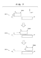
- FIG. 7 shows an operation example at the time of maintenance of each printhead 30 .
- a state ST 11 shows a state in which the print unit 3 is positioned at the discharge position POS 1 .
- a state ST 12 shows a state in which the print unit 3 passes through the preliminary recovery position POS 2 . Under passage, the recovery unit 12 performs a process of recovering discharge performance of each printhead 30 of the print unit 3 . Subsequently, as shown in a state ST 13 , the recovery unit 12 performs the process of recovering the discharge performance of each printhead 30 in a state in which the print unit 3 is positioned at the recovery position POS 3 .
- the printing system 1 can continuously transfer the ink image IM to the plurality of print media P in one rotation of the transfer member 2 .
- the print medium P may be a cut sheet of paper or another medium obtained for each printing operation of one image.
- the time taken to perform image processing in the higher level apparatus HC 2 and the main controller 13 A may, however, become longer than the unit transfer time.
- image data of 1,200 dpi is processed by these apparatuses.
- the processing amount of image processing for image data of 1,200 dpi is about four times greater than that for image data of 600 dpi.
- the processing time can increase up to about four times. Therefore, image processing for the image data of 1,200 dpi may take about four times the unit transfer time.
- the processing time can increase in accordance with print conditions represented by the time taken to process image data. For example, a data transfer time is accordingly prolonged depending on a data transfer line.
- the transfer member 2 , the conveyance apparatus 1 B, and the like continue the printing operation, the print medium P on which the ink image IM is transferred and the print medium P on which no ink image IM is transferred are mixed and output, and thus, the user needs to sort them.
- the image processing, and the like are not complete, the operations of the transfer member 2 , the conveyance apparatus 1 B, and the like, can be stopped. If, for example, image processing, and the like, for one image data are not complete, the operations of the transfer member 2 , the conveyance apparatus 1 B, and the like, are stopped.
- an image of 600 dpi is printed after printing the same image of 1,200 dpi on four sheets in an arrangement in which four sheets can be printed in one rotation of the transfer member 2 , all these printing operations are performed continuously. That is, the image processing, and the like, for the image data of 1,200 dpi are complete at the time of printing of the first sheet in the first rotation, and the second to fourth sheets can be printed using the result of the image processing, and the like. Since the image processing, and the like, for the subsequent image data of 600 dpi are completed within the unit transfer time, it is possible to print the image data of 600 dpi by printing of the first sheet in the second rotation.
- the rotation speed of the transfer member 2 and the conveyance speed of the print medium P by the conveyance apparatus 1 B can be decreased.
- the rotation speed and the conveyance speed are set to 1/N.
- the rotation speed and the conveyance speed can be decreased to 0.15 m/s, thereby executing printing. This can execute printing processing in accordance with the speed of the image processing, and the like.
- control the number of copies in one rotation of the transfer member 2 by processing of scheduling formation of the ink image on the transfer member 2 and conveyance of the print medium P by the conveyance apparatus 1 B and thinning out the formation of the ink image and conveyance of the print medium P. That is, in a state in which the rotation speed of the transfer member 2 and the conveyance speed of the print medium P by the conveyance apparatus 1 B are maintained constant and the image processing, and the like, are not complete, control is performed not to form the ink image on the transfer member 2 and not to convey the print medium P.
- the image processing, and the like take four times as long as the time taken for image data of 600 dpi, thereby executing printing during one of four periods in which image data can be printed.
- an ink image is formed not in areas, on the transfer member 2 , corresponding to the first to third sheets, but in an area corresponding to the fourth sheet.
- the conveyance apparatus 1 B does not convey the paper at timings corresponding to the first to third sheets, but conveys the paper at a timing corresponding to the fourth sheet.
- the following description will be provided by, particularly, paying attention to this method.
- the printing control unit 15 A executes processing for controlling the number of copies in one rotation of the transfer member 2 based on a print condition, such as a resolution indicating the time taken to process image data.
- a print condition such as a resolution indicating the time taken to process image data.
- the printing control unit 15 A includes, for example a Field Programmable Gate Array (FPGA) 803 and a CPU 805 .
- the FPGA 803 receives, via a communication I/F 801 , print data from the main controller 13 A, and accumulates it in a memory 802 .
- FPGA Field Programmable Gate Array
- the FPGA 803 controls the printheads 30 via a communication I/F 804 to discharge ink to the transfer member 2 at a timing based on a drum position control signal from the conveyance control unit 15 D after performing various image processes for the print data accumulated in the memory 802 . That is, the FPGA 803 specifies a rotation amount from the reference position of the transfer member 2 of the transfer drum 41 , and the like, by the drum position control signal, and controls an ink discharge timing so as to print a predetermined image at a predetermined position on the print medium P. The FPGA 803 also controls ink discharge of each printhead 30 and paper feed of feeding unit 7 .
- the FPGA 803 can control the paper feed by transmitting a paper feed stop request signal to the feeding unit 7 at a timing when the paper feed should be stopped.
- the feeding unit 7 can execute the paper feed unless, for example, such signal is received.
- the FPGA 803 may be configured to transmit a paper feed request signal at a timing when paper should be fed, and not to transmit such signal at a timing when paper should not be fed.
- the FPGA 803 can execute various processes based on instructions from the CPU 805 .
- the CPU 805 is connected to the internal LAN 17 to receive a control command, or the like, from another control unit and to transmit a control command, or the like, to another control unit.
- the CPU 805 is connected to a memory 806 to execute processing in accordance with various control commands, or the like, using, for example, the memory 806 as a working memory.
- the CPU 805 can generate, based on information of the print condition, such as a resolution concerning print target image data acquired from the main controller 13 A, a schedule to be used to actually execute printing, and to notify the FPGA 803 of information about the schedule.
- the information of the print condition such as a resolution concerning the image data
- the schedule used to execute printing may be in a form of a Print Order Table (POT) (to be described later).
- POT Print Order Table
- an output resolution is determined based on an instruction from the user when inputting original data to the higher level apparatus (DFE) HC 2 , and information of the resolution and information of the number of copies are sent to the printing control unit 15 A first. Then, the printing control unit 15 A can generate a schedule based on these pieces of information.
- DFE higher level apparatus
- the main controller 13 A transfers print data to the printing control unit 15 A, it is possible to generate a schedule on which the time taken for the DFE and the main controller 13 A to process the data is reflected.
- the main controller 13 A may generate the above-described schedule based on the print condition of the print target image data, and the CPU 805 may acquire information of the generated schedule.
- the CPU 805 or the main controller 13 A can generate the schedule by reflecting one of the time taken for the DFE to process the original data and the time taken for the main controller 13 A to process the data, or generate the schedule in accordance with both the processing times.
- the FPGA 803 executes control not to feed paper or to discharge ink at a timing when no printing is executed and to feed paper and to discharge ink only at a timing when printing is executed due to the schedule. This can prevent, when image processing is not complete for, for example, image data of a high resolution in accordance with the print condition, the print medium, on which no ink image is transferred, from being conveyed, or printing processing from failing. Furthermore, the FPGA 803 may control to discharge ink, for example, only when the feeding unit 7 receives a paper leading edge detection signal indicating that the leading edge of paper (print medium P) has been detected, that is, only when the print medium P is actually conveyed.
- no ink image is formed on the transfer member 2 , thereby making it possible to prevent ink from adhering to, for example, the pressurizing drum 42 .
- the printing control unit 15 A may be connected to the conveyance control unit 15 D and the feeding unit 7 via, for example, the internal LAN 17 , but may be connected to these functional units using dedicated lines.
- the printing control unit 15 A includes the FPGA 803 .
- the FPGA 803 may be replaced, however, by another processor, such as an Application Specific Integrated Circuit (ASIC) or a Digital Signal Processor (DSP).
- ASIC Application Specific Integrated Circuit
- DSP Digital Signal Processor
- FIG. 9 shows an example of a functional arrangement implemented by the FPGA 803 .
- the FPGA 803 is configured to include the functions of a head data transmission unit 901 , image processing unit 902 , POT control unit 903 , timing control unit 904 , DMAC 905 , reception data control unit 906 , and CPU I/F 907 .
- the FPGA 803 causes the reception data control unit 906 to acquire print data from the main controller 13 A and to accumulate it.
- the reception data control unit 906 activates the DMAC 905 in accordance with accumulation of data of an amount that can be written in the memory 802 , causing the DMAC 905 to write the accumulated data in the memory 802 .
- the POT control unit 903 acquires a print order table (POT) indicating a print schedule from the CPU 805 via the CPU I/F 907 serving as an interface with the CPU 805 .
- POT print order table
- FIG. 10 shows an example of the POT.
- the POT is a table that associates the print ordinal number of each image with the number of copies of the image.
- N copies of image 1 are printed, one copy of image 2 is printed.
- N copies of image 3, one copy of image 4, one copy of image 5, and one copy of image 3 are printed, and one copy of image G is printed at the last, thereby ending printing.
- the POT control unit 903 acquires another POT while executing printing processing in accordance with the POT shown in FIG. 10 , it can add a print schedule included in the acquired POT to the end of the current POT.
- the POT control unit 903 causes the image processing unit 902 to execute each image processing for allowing printing by the ink image of the print target image in accordance with the POT, and causes the head data transmission unit 901 to control the printheads 30 so as to form an ink image according to the processed image on the transfer member 2 .
- the POT control unit 903 loads the first row of the POT to set image 1 as a print target, and transmits a timing control signal to the image processing unit 902 so as to start image processing related to the print target image before forming the ink image on the transfer member 2 .
- the POT control unit 903 transmits a timing control signal to the head data transmission unit 901 to form, at an appropriate position on the transfer member 2 , an ink image related to the image having undergone the image processing.
- the POT control unit 903 may transmit one timing control signal to both the head data transmission unit 901 and the image processing unit 902 .
- the image processing unit 902 can start the processing immediately after the signal is received, and the head data transmission unit 901 can transmit a signal for controlling each printhead 30 to discharge ink after a predetermined time elapses since the signal is received.
- the POT control unit 903 transmits a timing control signal to the head data transmission unit 901 so as to print N copies of image 1. After that, the POT control unit 903 loads the second row of the POT to set image 2 as a print target, and transmits a timing control signal to each of the head data transmission unit 901 and the image processing unit 902 .
- the timing control unit 904 can receive the drum position control signal from the conveyance control unit 15 D, and provide the POT control unit 903 with information as the reference of the timing of the processing for executing ink image formation processing. For example, the POT control unit 903 generates the above-described timing control signal based on the timing provided from the timing control unit 904 .
- image data of 600 dpi can be sequentially printed in accordance with the POT shown in FIG. 10 . If a long time is required for image processing, such as printing of image data of 1,200 dpi, however, the image processing is incomplete at a print timing. In accordance with the POT shown in FIG. 10 , for example, the print medium is only conveyed without transferring the ink image.
- contents of the POT are set based on the print condition, such as a resolution. For example, if the image processing, and the like, for image data of 1,200 dpi take four times the unit transfer time, information indicating that there is no print target data in three of the four unit transfer times is included in the POT. Then, the POT control unit 903 transmits the timing control signal to each of the head data transmission unit 901 and the image processing unit 902 so as to print data for which the image processing, and the like, are complete during the periods in which it is indicated that there is no data.
- FIG. 11 shows an example of the POT in this case.
- the example of FIG. 11 shows a case in which images 2 to 4 are images of 1,200 dpi and the remaining images are images of 600 dpi in the arrangement designed to complete image processing for image data of 600 dpi within the unit transfer time. Note that in this example, the image processing, and the like, for the image of 1,200 dpi end within four times the unit transfer time.
- image 2 of 1,200 dpi “Non” indicating that there is no print target for “three” successive print media is included in the POT and, after that, information about image 2 is included in the POT.
- the POT control unit 903 controls the printheads 30 to stop the formation of the ink image without stopping the rotation of the transfer member 2 based on the time taken to perform predetermined processing such as image processing with respect to printing of an image with 1,200 dpi as the print condition. Furthermore, the POT control unit 903 controls the feeding unit 7 to stop the supply of the print medium without stopping each drum associated with conveyance of the print medium based on the time taken to perform predetermined processing such as image processing.
- image 3 of 1,200 dpi as well, “Non” indicating that there is no print target for “three” successive print media is included in the POT and, after that, information about image 3 is included in the POT. If two copies of image 3 are printed, it is unnecessary to execute the image processing, and the like, again in the stage of printing processing of the second copy, and thus, processing associated with the next image data can start.
- the POT control unit 903 can perform a readout operation from the POT with respect to the image of the next print target, and send the timing control signal to the image processing unit 902 so as to execute image processing.
- the POT control unit 903 can stand by until the period of “Non” elapses, and send the timing control signal to the head data transmission unit 901 so as to form the ink image on the transfer member 2 in accordance with the timing of printing the image of the next print target.
- the POT shown in FIG. 11 may include print condition information, such as resolution information, as shown in FIG. 12 .
- Each of the POTs shown in FIGS. 11 and 12 stores print target data in, for example, a structure shown in FIG. 13 .
- FIG. 13 shows an example of the structure of one print target data.
- the serial number of the print target is expressed in four bytes
- a mode is expressed in one byte
- the number of copies is expressed in two bytes.
- information indicating the resolution is expressed in, for example, one byte.
- a value associated with each state is stored in the “mode”.
- “0x01” is stored for 600 dpi
- “0x02” is stored for 1,200 dpi
- “0x00” is stored for 0 dpi corresponding to a case in which the mode is “Non” or “end”.
- another value may be used as the value of the resolution.
- a value except for 0x00 to 0x02 is used as a value indicating the resolution.
- FIG. 14 An example of the sequence of the printing processing executed in accordance with the POT shown in FIG. 11 or 12 will be described with reference to FIG. 14 .
- This processing starts due to various factors, such as power-on of the printing system, execution of a processing start operation, and occurrence of a print job.
- the printing control unit 15 A starts this processing in response to acquisition of the information from the main controller 13 A.
- the printing control unit 15 A generates the above-described POT based on the information acquired from the main controller 13 A or acquires the POT from the main controller 13 A, and sets the POT (step S 1401 ).
- the main controller 13 A or the printing control unit 15 A outputs a control command to another control unit via, for example, the internal LAN 17 , and starts rotation of the drums (step S 1402 ).
- Printing processing according to the POT set in step S 1401 starts (step S 1403 ). After that, the printing processing is continued until all jobs end (until YES is determined in step S 1404 ). If the POT is updated by information about a new job, or the like, before all the jobs end (NO in step S 1404 ), the current POT is updated or replaced by the new POT, thereby setting the POT (step S 1405 ).
- FIG. 15 shows an example of processing when the POT shown in FIG. 11 or 12 is used.
- the example of FIG. 15 shows an example of the printing system in which four sheets can be printed in one rotation of the transfer member, image processing, and the like, for an image of 600 dpi are completed within the unit transfer time, and image processing, and the like, for an image of 1,200 dpi take four times the unit transfer time.
- image 1 of 600 dpi is printed on the first sheet of the first rotation. Since image 1 has 600 dpi, a delay caused by the image processing, and the like, falls within a sufficiently small range, and thus, no period of “Non” is set.
- the printing system attempts to print image 2 of 1,200 dpi. Since, however, a delay caused by the image processing, and the like, for image 2 is large, “Non” is set in a period for the image processing, and the like, that is, a period of the second to fourth sheets of the first rotation, and then image 2 is printed on the first sheet of the second rotation. Since image 3 is an image of 1,200 dpi, “Non” is set in a period of the second to fourth sheets of the second rotation as a period for the image processing, and the like, image 3 is printed on the first sheet of the third rotation. Note that image 3 is also printed on the second sheet of the third rotation, thereby printing two sheets in total.
- image processing, and the like, for image 3 are complete at the time of the first sheet of the third rotation, image 3 is printed on the second sheet continuously from the first sheet. Since image 4 is an image of 1,200 dpi, the period of “Non” for the image processing, and the like, is set. Note that since an image processing circuit, and the like, can be in a state in which processing of the next image is possible at the time of printing of image 3 on the second sheet, image processing, and the like, associated with image 4 can be started in parallel to printing of image 3 on the second sheet. After that, image 4 is printed in a period of the first sheet of the fourth rotation. After that, since images 5 to 7 are images of 600 dpi, they are printed continuously in a period of the second to fourth sheets of the fourth rotation after printing of image 4.
- the printing control unit 15 A can control the printheads 30 so as to form the ink image on the transfer member 2 in response to reception of the paper leading edge detection signal from the feeding unit 7 , as described above. That is, for example, if the leading edge of the print medium (paper) is not detected at a timing corresponding to the period of the first sheet of the second rotation, it is attempted to print image 2 in the period of the second sheet of the second rotation. If the leading edge of the print medium is detected at a timing corresponding to the period of the second sheet of the second rotation, the printheads 30 can be controlled to form the ink image of image 2 on the transfer member 2 .
- image processing, and the like, associated with image 3 can be started in the period of the second sheet of the second rotation, and it is thus possible to prevent printing of image 3, or the like, from being delayed due to the delay of printing of image 2.
- the printing control unit 15 A can transmit a paper feed stop request to the feeding unit 7 to stop the feeding of the print medium in the period set for “Non”.
- the paper feed stop request can be sent after receiving the paper leading edge detection signal at a timing corresponding to a period during which the first sheet of the first rotation, or the like, in FIG. 15 is actually printed.
- FIG. 16 shows examples of the control signals. Processing starts in response to input of a print command. After that, in response to feeding of the print medium to print one image, the feeding unit 7 sends the paper leading edge detection signal. After that, in accordance with, for example, the POT, no printing is executed in three periods. In this case, after receiving the paper leading edge detection signal associated with the first image, the printing control unit 15 A outputs the paper feed stop request three times. This prevents three paper feeding operations. FIG. 16 shows this state by dotted lines. After that, the feeding unit 7 restarts feeding the print medium when no paper feed stop request is received. In this way, it is possible to prevent the print medium, on which no ink image is transferred, from being conveyed and output intact.
- the rotation speed of the transfer drum 41 and the rotation speed of each drum in the transfer unit 4 are decreased, and the conveyance period of the print medium P in the feeding unit 7 is prolonged, thereby making it possible to cope with a delay caused by the image processing, and the like, at the time of printing of a high-resolution image.
- the rotation speed of the transfer drum 41 and that of each drum in the transfer unit 4 are decreased to 1 ⁇ 4 and the conveyance period of the print medium P in the feeding unit 7 is prolonged to four times.
- FIGS. 17A and 17B show this state.
- FIG. 17A shows an example of the operation of the transfer drum 41 and the operation of the printing processing at the time of a normal operation.
- FIG. 17B shows an example of the operation of the transfer drum 41 and the operation of the printing processing when printing of an image of 1,200 dpi is included.
- FIGS. 17A and 17B if an image of 1,200 dpi is included in print target images, as compared to a case in which all print target images are images of 600 dpi, the number of images that can be printed in one rotation of the transfer member 2 is the same but one rotation takes four times longer. At this time, for example, if printing is executed at a linear velocity of 0.6 m/s in the state shown in FIG.
- printing is executed at 0.15 m/s in the state shown in FIG. 17B .
- the image of 600 dpi is also printed at the same velocity as that when the image of 1,200 dpi is printed.
- the operation of the printing processing may be returned to the normal operation. This processing can execute the printing processing at a low velocity when an image requiring a long time for the image processing, and the like, is printed, and can execute the printing processing at a high velocity when there is no image requiring long time for the image processing, and the like.
- This processing can be performed when, for example, the printing control unit 15 A transmits a control command to the conveyance control unit 15 D, or the like, to decrease the conveyance speed of the printing medium or the rotation speed of the transfer drum 41 .
- the printing control unit 15 A can notify, for example, the transfer control unit 15 B that the mode of the printing processing is changed.
- the transfer control unit 15 B can hold transfer control parameters with respect to, for example, a normal mode of printing an image of 600 dpi and a low-velocity mode of printing an image of 1,200 dpi, and can execute printing processing by setting the parameters every time the mode is designated.
- various parameters different from those in the normal mode are used to, for example, control to prevent excessive heating of the ink image by lowering the heating temperature of the heating unit 5 C or a temperature for drying the print medium on which the ink image is transferred after printing.
- control to prevent excessive heating of the ink image by lowering the heating temperature of the heating unit 5 C or a temperature for drying the print medium on which the ink image is transferred after printing.
- the time taken for the image processing, and the like, for an image of 1,200 dpi is four times longer than the unit transfer time or the time taken for the image processing, and the like, for an image of 600 dpi.
- a predetermined value may be used as this value, or this value may be determined based on the actual operation. For example, by executing, in advance, test printing of an image of 600 dpi and an image of 1,200 dpi, the times taken for the respective image processes may be specified.
- the time taken for the image processing for the image of 1,200 dpi falls within the range of the unit transfer time, even if the image of 600 dpi and the image of 1,200 dpi are mixed, all printing processes can be executed by the normal operation.
- the period of “Non” can be shortened from the period of three sheets to the period of one sheet in, for example, the POT shown in FIG. 11 or 12 .
- the print unit 3 includes the plurality of printheads 30 .
- a print unit 3 may, however, include one printhead 30 .
- the printhead 30 may not be a full-line head, but may be of a serial type that forms an ink image while scanning the printhead 30 in a Y direction.
- a conveyance mechanism of the print medium P may adopt another method, such as a method of clipping and conveying the print medium P by the pair of rollers.
- a roll sheet may be used as the print medium P, and a printed product P′ may be formed by cutting the roll sheet after transfer.
- the transfer member 2 is provided on the outer peripheral surface of the transfer drum 41 .
- Another method such as a method of forming a transfer member 2 into an endless swath and running it cyclically may, however, be used. That is, the transfer member 2 may circulate a path of an arbitrary shape instead of a circle.
- the above-described embodiment can be applied by controlling to change the number of copies per period of circulation based on the print condition related to the time taken to process image data.
- Embodiments of the present invention can also be realized by a computer of a system or an apparatus that reads out and executes computer executable instructions (e.g., one or more programs) recorded on a storage medium (which may also be referred to more fully as a ‘non-transitory computer-readable storage medium’) to perform the functions of one or more of the above-described embodiments and/or that includes one or more circuits (e.g., an application specific integrated circuit (ASIC)) for performing the functions of one or more of the above-described embodiments, and by a method performed by the computer of the system or the apparatus by, for example, reading out and executing the computer executable instructions from the storage medium to perform the functions of one or more of the above-described embodiments and/or controlling the one or more circuits to perform the functions of one or more of the above-described embodiments.
- ASIC application specific integrated circuit
- the computer may comprise one or more processors (e.g., a central processing unit (CPU), or a micro processing unit (MPU)) and may include a network of separate computers or separate processors to read out and to execute the computer executable instructions.
- the computer executable instructions may be provided to the computer, for example, from a network or the storage medium.
- the storage medium may include, for example, one or more of a hard disk, a random access memory (RAM), a read only memory (ROM), a storage of distributed computing systems, an optical disk (such as a compact disc (CD), a digital versatile disc (DVD), or a Blu-ray Disc (BD)TM) a flash memory device, a memory card, and the like.
Abstract
Description
Claims (23)
Applications Claiming Priority (2)
| Application Number | Priority Date | Filing Date | Title |
|---|---|---|---|
| JP2017-063749 | 2017-03-28 | ||
| JP2017063749A JP6940968B2 (en) | 2017-03-28 | 2017-03-28 | Recording devices, recording systems, control methods, and programs |
Publications (2)
| Publication Number | Publication Date |
|---|---|
| US20180281382A1 US20180281382A1 (en) | 2018-10-04 |
| US10500840B2 true US10500840B2 (en) | 2019-12-10 |
Family
ID=61598836
Family Applications (1)
| Application Number | Title | Priority Date | Filing Date |
|---|---|---|---|
| US15/925,856 Expired - Fee Related US10500840B2 (en) | 2017-03-28 | 2018-03-20 | Printing apparatus and control method that control movement of a transfer member |
Country Status (5)
| Country | Link |
|---|---|
| US (1) | US10500840B2 (en) |
| EP (1) | EP3381686A1 (en) |
| JP (1) | JP6940968B2 (en) |
| KR (1) | KR20180109701A (en) |
| CN (1) | CN108656739B (en) |
Families Citing this family (5)
| Publication number | Priority date | Publication date | Assignee | Title |
|---|---|---|---|---|
| US11809100B2 (en) | 2012-03-05 | 2023-11-07 | Landa Corporation Ltd. | Intermediate transfer members for use with indirect printing systems and protonatable intermediate transfer members for use with indirect printing systems |
| US9643403B2 (en) | 2012-03-05 | 2017-05-09 | Landa Corporation Ltd. | Printing system |
| GB201609463D0 (en) | 2016-05-30 | 2016-07-13 | Landa Labs 2012 Ltd | Method of manufacturing a multi-layer article |
| US11707943B2 (en) | 2017-12-06 | 2023-07-25 | Landa Corporation Ltd. | Method and apparatus for digital printing |
| JP2023505035A (en) | 2019-11-25 | 2023-02-08 | ランダ コーポレイション リミテッド | Ink drying in digital printing using infrared radiation absorbed by particles embedded inside the ITM |
Citations (12)
| Publication number | Priority date | Publication date | Assignee | Title |
|---|---|---|---|---|
| JPS60157874A (en) | 1984-01-28 | 1985-08-19 | Citizen Watch Co Ltd | Discharge-type non-impact printer |
| CN1050097A (en) | 1989-07-28 | 1991-03-20 | 佳能株式会社 | Image processing system |
| CN1055897A (en) | 1990-04-20 | 1991-11-06 | 佳能株式会社 | A kind of tape deck |
| US5372852A (en) | 1992-11-25 | 1994-12-13 | Tektronix, Inc. | Indirect printing process for applying selective phase change ink compositions to substrates |
| CN1188913A (en) | 1997-01-22 | 1998-07-29 | 株式会社东芝 | Image forming apparatus and image forming method |
| CN1215187A (en) | 1997-10-16 | 1999-04-28 | 精工爱普生株式会社 | Printing device and control method for restarting |
| US6282388B1 (en) | 2000-02-18 | 2001-08-28 | Toshiba Tec Kabushiki Kaisha | Image forming apparatus and image forming method with precedent pre-output processing of a print start command |
| US6494570B1 (en) | 2001-12-04 | 2002-12-17 | Xerox Corporation | Controlling gloss in an offset ink jet printer |
| US20030085975A1 (en) | 1998-12-16 | 2003-05-08 | Kia Silverbrook | Printer transport roller with internal drive motor |
| JP2005153187A (en) | 2003-11-20 | 2005-06-16 | Canon Inc | Image formation method and image forming apparatus |
| US20060001722A1 (en) * | 2004-06-30 | 2006-01-05 | Stelter Eric C | Phase-change ink jet printing with electrostatic transfer |
| CN105711251A (en) | 2014-12-17 | 2016-06-29 | 海德堡印刷机械股份公司 | Simultaneous alignment of multiple tasks |
Family Cites Families (4)
| Publication number | Priority date | Publication date | Assignee | Title |
|---|---|---|---|---|
| JP2895158B2 (en) * | 1990-04-20 | 1999-05-24 | キヤノン株式会社 | Recording device |
| US20060000172A1 (en) * | 2001-06-22 | 2006-01-05 | Amazon Forms One, Inc. | Lightweight concrete composite blocks |
| JP4650357B2 (en) * | 2006-07-03 | 2011-03-16 | 富士ゼロックス株式会社 | Continuous paper printing apparatus and continuous paper printing system |
| JP2016064606A (en) * | 2014-09-25 | 2016-04-28 | キヤノン株式会社 | Printing system, printer, and control method of printing system |
-
2017
- 2017-03-28 JP JP2017063749A patent/JP6940968B2/en active Active
-
2018
- 2018-03-07 EP EP18000228.9A patent/EP3381686A1/en not_active Withdrawn
- 2018-03-20 KR KR1020180031964A patent/KR20180109701A/en not_active Application Discontinuation
- 2018-03-20 US US15/925,856 patent/US10500840B2/en not_active Expired - Fee Related
- 2018-03-27 CN CN201810255941.8A patent/CN108656739B/en not_active Expired - Fee Related
Patent Citations (18)
| Publication number | Priority date | Publication date | Assignee | Title |
|---|---|---|---|---|
| JPS60157874A (en) | 1984-01-28 | 1985-08-19 | Citizen Watch Co Ltd | Discharge-type non-impact printer |
| CN1050097A (en) | 1989-07-28 | 1991-03-20 | 佳能株式会社 | Image processing system |
| US5455603A (en) | 1989-07-28 | 1995-10-03 | Canon Kabushiki Kaisha | Image forming apparatus with feeder control based on pixel conversion status |
| CN1055897A (en) | 1990-04-20 | 1991-11-06 | 佳能株式会社 | A kind of tape deck |
| US5223858A (en) * | 1990-04-20 | 1993-06-29 | Canon Kabushiki Kaisha | Recording apparatus |
| US5372852A (en) | 1992-11-25 | 1994-12-13 | Tektronix, Inc. | Indirect printing process for applying selective phase change ink compositions to substrates |
| US6125242A (en) | 1997-01-22 | 2000-09-26 | Kabushiki Kaisha Toshiba | Image forming method that switches from an empty paper cassette to a non-empty paper cassette |
| CN1188913A (en) | 1997-01-22 | 1998-07-29 | 株式会社东芝 | Image forming apparatus and image forming method |
| CN1215187A (en) | 1997-10-16 | 1999-04-28 | 精工爱普生株式会社 | Printing device and control method for restarting |
| US6364442B1 (en) | 1997-10-16 | 2002-04-02 | Seiko Epson Corporation | Printing apparatus, and a control method for resetting the printing apparatus |
| US20030085975A1 (en) | 1998-12-16 | 2003-05-08 | Kia Silverbrook | Printer transport roller with internal drive motor |
| US6631986B2 (en) | 1998-12-16 | 2003-10-14 | Silverbrook Research Pty Ltd | Printer transport roller with internal drive motor |
| US6282388B1 (en) | 2000-02-18 | 2001-08-28 | Toshiba Tec Kabushiki Kaisha | Image forming apparatus and image forming method with precedent pre-output processing of a print start command |
| US6494570B1 (en) | 2001-12-04 | 2002-12-17 | Xerox Corporation | Controlling gloss in an offset ink jet printer |
| JP2005153187A (en) | 2003-11-20 | 2005-06-16 | Canon Inc | Image formation method and image forming apparatus |
| US7661809B2 (en) | 2003-11-20 | 2010-02-16 | Canon Kabushiki Kaisha | Method and apparatus for forming image |
| US20060001722A1 (en) * | 2004-06-30 | 2006-01-05 | Stelter Eric C | Phase-change ink jet printing with electrostatic transfer |
| CN105711251A (en) | 2014-12-17 | 2016-06-29 | 海德堡印刷机械股份公司 | Simultaneous alignment of multiple tasks |
Non-Patent Citations (1)
| Title |
|---|
| Extended European Search Report dated Jul. 31, 2018, in European Application No. 18000228.9. |
Also Published As
| Publication number | Publication date |
|---|---|
| JP2018165036A (en) | 2018-10-25 |
| KR20180109701A (en) | 2018-10-08 |
| US20180281382A1 (en) | 2018-10-04 |
| CN108656739A (en) | 2018-10-16 |
| CN108656739B (en) | 2019-11-22 |
| JP6940968B2 (en) | 2021-09-29 |
| EP3381686A1 (en) | 2018-10-03 |
Similar Documents
| Publication | Publication Date | Title |
|---|---|---|
| US10500840B2 (en) | Printing apparatus and control method that control movement of a transfer member | |
| US11072177B2 (en) | Liquid absorbing apparatus, printing apparatus, printing method, and manufacturing method | |
| US20190009594A1 (en) | Printing apparatus, liquid absorbing apparatus, and control method | |
| US20190009546A1 (en) | Printing apparatus, liquid absorbing apparatus, and control method | |
| US10500839B2 (en) | Inkjet printing apparatus and related printing method in which a liquid applied to a transfer member is dried before ink is discharged by a printhead | |
| US10755151B2 (en) | Inkjet printing apparatus and control method therefor | |
| US10252516B2 (en) | Printing apparatus, liquid absorbing apparatus, and method | |
| US11192373B2 (en) | Printing apparatus and control method thereof | |
| US10421271B2 (en) | Printing apparatus and control method | |
| US10486441B2 (en) | Printing apparatus, inspection apparatus, and method of controlling the inspection apparatus in which a fixing unit fixes a relative position between a detection surface of a reading unit and a print medium | |
| US10549527B2 (en) | Printing apparatus, printing system, control method, and non-transitory computer-readable storage medium | |
| US10618274B2 (en) | Printing apparatus and control method | |
| US10427427B2 (en) | Printing apparatus that detects whether a print medium runs out and, during double-sided printing, discards image data to be printed on the run out print medium, and related print control method | |
| US10611140B2 (en) | Inkjet printing apparatus | |
| US20200047529A1 (en) | Printing apparatus, cleaning device, and printing method | |
| US10350894B2 (en) | Printing apparatus | |
| US20200047487A1 (en) | Printing apparatus, and printing method | |
| US20180290469A1 (en) | Printing apparatus | |
| US10493781B2 (en) | Printing apparatus, liquid absorbing apparatus, and control method | |
| US10464309B2 (en) | Printing apparatus and control method | |
| US20200047517A1 (en) | Printing apparatus and control method thereof | |
| US11667141B2 (en) | Printing apparatus, control method therefor, and storage medium | |
| US20200047520A1 (en) | Printing apparatus and printing method | |
| US10369780B2 (en) | Printing apparatus |
Legal Events
| Date | Code | Title | Description |
|---|---|---|---|
| FEPP | Fee payment procedure |
Free format text: ENTITY STATUS SET TO UNDISCOUNTED (ORIGINAL EVENT CODE: BIG.); ENTITY STATUS OF PATENT OWNER: LARGE ENTITY |
|
| AS | Assignment |
Owner name: CANON KABUSHIKI KAISHA, JAPAN Free format text: ASSIGNMENT OF ASSIGNORS INTEREST;ASSIGNORS:UMEZAWA, MASAHIKO;KITAI, SATOSHI;SERIZAWA, KOUICHI;AND OTHERS;REEL/FRAME:046288/0663 Effective date: 20180312 |
|
| STPP | Information on status: patent application and granting procedure in general |
Free format text: RESPONSE TO NON-FINAL OFFICE ACTION ENTERED AND FORWARDED TO EXAMINER |
|
| STPP | Information on status: patent application and granting procedure in general |
Free format text: NOTICE OF ALLOWANCE MAILED -- APPLICATION RECEIVED IN OFFICE OF PUBLICATIONS |
|
| STPP | Information on status: patent application and granting procedure in general |
Free format text: DOCKETED NEW CASE - READY FOR EXAMINATION |
|
| STPP | Information on status: patent application and granting procedure in general |
Free format text: NOTICE OF ALLOWANCE MAILED -- APPLICATION RECEIVED IN OFFICE OF PUBLICATIONS |
|
| STCF | Information on status: patent grant |
Free format text: PATENTED CASE |
|
| FEPP | Fee payment procedure |
Free format text: MAINTENANCE FEE REMINDER MAILED (ORIGINAL EVENT CODE: REM.); ENTITY STATUS OF PATENT OWNER: LARGE ENTITY |
|
| LAPS | Lapse for failure to pay maintenance fees |
Free format text: PATENT EXPIRED FOR FAILURE TO PAY MAINTENANCE FEES (ORIGINAL EVENT CODE: EXP.); ENTITY STATUS OF PATENT OWNER: LARGE ENTITY |
|
| STCH | Information on status: patent discontinuation |
Free format text: PATENT EXPIRED DUE TO NONPAYMENT OF MAINTENANCE FEES UNDER 37 CFR 1.362 |
|
| FP | Lapsed due to failure to pay maintenance fee |
Effective date: 20231210 |