US10495771B2 - Method and system for processing dipole anisotropy - Google Patents
Method and system for processing dipole anisotropy Download PDFInfo
- Publication number
- US10495771B2 US10495771B2 US15/333,199 US201615333199A US10495771B2 US 10495771 B2 US10495771 B2 US 10495771B2 US 201615333199 A US201615333199 A US 201615333199A US 10495771 B2 US10495771 B2 US 10495771B2
- Authority
- US
- United States
- Prior art keywords
- dipole
- firing
- drilling
- wave data
- formation
- Prior art date
- Legal status (The legal status is an assumption and is not a legal conclusion. Google has not performed a legal analysis and makes no representation as to the accuracy of the status listed.)
- Active, expires
Links
- 238000012545 processing Methods 0.000 title claims abstract description 49
- 238000000034 method Methods 0.000 title claims abstract description 48
- 238000010304 firing Methods 0.000 claims abstract description 71
- 230000015572 biosynthetic process Effects 0.000 claims abstract description 42
- 238000005553 drilling Methods 0.000 claims description 50
- 238000004519 manufacturing process Methods 0.000 claims description 7
- 238000004891 communication Methods 0.000 claims description 3
- 238000005259 measurement Methods 0.000 abstract description 16
- 238000003908 quality control method Methods 0.000 abstract description 7
- 238000005755 formation reaction Methods 0.000 description 29
- 230000005284 excitation Effects 0.000 description 9
- 239000012530 fluid Substances 0.000 description 6
- 238000003860 storage Methods 0.000 description 6
- 230000008901 benefit Effects 0.000 description 4
- 239000000463 material Substances 0.000 description 4
- 238000012986 modification Methods 0.000 description 4
- 230000004048 modification Effects 0.000 description 4
- 238000010586 diagram Methods 0.000 description 3
- 239000006185 dispersion Substances 0.000 description 3
- 101100412856 Mus musculus Rhod gene Proteins 0.000 description 2
- 230000001419 dependent effect Effects 0.000 description 2
- 238000011161 development Methods 0.000 description 2
- 238000011156 evaluation Methods 0.000 description 2
- 230000006870 function Effects 0.000 description 2
- 238000012544 monitoring process Methods 0.000 description 2
- 230000005404 monopole Effects 0.000 description 2
- 239000011435 rock Substances 0.000 description 2
- 230000001360 synchronised effect Effects 0.000 description 2
- 101150054980 Rhob gene Proteins 0.000 description 1
- 238000013459 approach Methods 0.000 description 1
- 230000000903 blocking effect Effects 0.000 description 1
- 230000001413 cellular effect Effects 0.000 description 1
- 239000004568 cement Substances 0.000 description 1
- 230000007797 corrosion Effects 0.000 description 1
- 238000005260 corrosion Methods 0.000 description 1
- 239000013078 crystal Substances 0.000 description 1
- 238000005520 cutting process Methods 0.000 description 1
- 238000003384 imaging method Methods 0.000 description 1
- 239000004973 liquid crystal related substance Substances 0.000 description 1
- 238000000691 measurement method Methods 0.000 description 1
- 230000003287 optical effect Effects 0.000 description 1
- 239000002245 particle Substances 0.000 description 1
- 230000000704 physical effect Effects 0.000 description 1
- 230000000644 propagated effect Effects 0.000 description 1
- 230000001902 propagating effect Effects 0.000 description 1
- 230000000630 rising effect Effects 0.000 description 1
- 230000035939 shock Effects 0.000 description 1
- 230000003068 static effect Effects 0.000 description 1
- 238000007619 statistical method Methods 0.000 description 1
- 238000012360 testing method Methods 0.000 description 1
- XLYOFNOQVPJJNP-UHFFFAOYSA-N water Substances O XLYOFNOQVPJJNP-UHFFFAOYSA-N 0.000 description 1
Images


Classifications
-
- G—PHYSICS
- G01—MEASURING; TESTING
- G01V—GEOPHYSICS; GRAVITATIONAL MEASUREMENTS; DETECTING MASSES OR OBJECTS; TAGS
- G01V1/00—Seismology; Seismic or acoustic prospecting or detecting
- G01V1/40—Seismology; Seismic or acoustic prospecting or detecting specially adapted for well-logging
- G01V1/44—Seismology; Seismic or acoustic prospecting or detecting specially adapted for well-logging using generators and receivers in the same well
- G01V1/48—Processing data
- G01V1/50—Analysing data
-
- G—PHYSICS
- G01—MEASURING; TESTING
- G01V—GEOPHYSICS; GRAVITATIONAL MEASUREMENTS; DETECTING MASSES OR OBJECTS; TAGS
- G01V1/00—Seismology; Seismic or acoustic prospecting or detecting
- G01V1/28—Processing seismic data, e.g. for interpretation or for event detection
- G01V1/284—Application of the shear wave component and/or several components of the seismic signal
-
- G—PHYSICS
- G01—MEASURING; TESTING
- G01V—GEOPHYSICS; GRAVITATIONAL MEASUREMENTS; DETECTING MASSES OR OBJECTS; TAGS
- G01V1/00—Seismology; Seismic or acoustic prospecting or detecting
- G01V1/28—Processing seismic data, e.g. for interpretation or for event detection
- G01V1/30—Analysis
- G01V1/303—Analysis for determining velocity profiles or travel times
-
- G—PHYSICS
- G01—MEASURING; TESTING
- G01V—GEOPHYSICS; GRAVITATIONAL MEASUREMENTS; DETECTING MASSES OR OBJECTS; TAGS
- G01V1/00—Seismology; Seismic or acoustic prospecting or detecting
- G01V1/24—Recording seismic data
-
- G—PHYSICS
- G01—MEASURING; TESTING
- G01V—GEOPHYSICS; GRAVITATIONAL MEASUREMENTS; DETECTING MASSES OR OBJECTS; TAGS
- G01V2200/00—Details of seismic or acoustic prospecting or detecting in general
- G01V2200/10—Miscellaneous details
- G01V2200/16—Measure-while-drilling or logging-while-drilling
-
- G—PHYSICS
- G01—MEASURING; TESTING
- G01V—GEOPHYSICS; GRAVITATIONAL MEASUREMENTS; DETECTING MASSES OR OBJECTS; TAGS
- G01V2210/00—Details of seismic processing or analysis
- G01V2210/60—Analysis
- G01V2210/62—Physical property of subsurface
- G01V2210/622—Velocity, density or impedance
- G01V2210/6222—Velocity; travel time
-
- G—PHYSICS
- G01—MEASURING; TESTING
- G01V—GEOPHYSICS; GRAVITATIONAL MEASUREMENTS; DETECTING MASSES OR OBJECTS; TAGS
- G01V2210/00—Details of seismic processing or analysis
- G01V2210/60—Analysis
- G01V2210/62—Physical property of subsurface
- G01V2210/626—Physical property of subsurface with anisotropy
Definitions
- the present disclosure relates generally to methods and systems method and system for processing sonic data measured with a downhole tool.
- the present disclosure relates to methods and systems for estimating anisotropic properties of formation from acoustic data measured with a downhole tool such as a LWD (logging-while-drilling), MWD (measurements while drilling) tool or wireline logging tool.
- a downhole tool such as a LWD (logging-while-drilling), MWD (measurements while drilling) tool or wireline logging tool.
- acoustic measurements can be used to measure characteristics of the surrounding formation.
- Acoustic measurement techniques generally involve sensing acoustic waves generated by one or more acoustic sources and that have propagated through a geological formation.
- a geological formation whose rock properties are the same in all directions is an “isotropic” formation.
- anisotropy i.e., a predictable variation of a physical property of a material with the direction in which it is measured.
- This “anisotropic” formation is a geological formation with directionally dependent properties and commonly caused by anisotropy of the constituting crystals, alignment of oblate particles, fine-scale layering or aligned and quasi-aligned fractures.
- a numerical rotation method of Alford is used for estimating anisotropic properties of formation.
- This method is commonly referred to “Alford rotation” and a processing technique to project formation shear data measured in any two orthogonal directions into the fast and slow shear directions in the presence of shear-wave anisotropy, as described in the document of Alford, R. M., “Shear Data in the Presence of Azimuthal Anisotropy: Dilley, Tex.”, Expanded Abstracts, 56th SEG Annual International Meeting and Exposition, Houston, Tex., USA, Nov. 2-6, 1986, pp. 476-479, the content of which is incorporated herein in its entirety by reference thereto.
- a method for processing sonic data measured with a downhole tool comprises acquiring dipole wave data measured by a dipole acquisition in multiple firing, and estimating at least one of formation anisotropy properties based on the multiple firing dipole data.
- the at least one of formation anisotropy properties may be derived by Alford rotation processing
- the dipole acquisition may comprise at least one of a cross dipole acquisition and a single dipole acquisition
- the formation anisotropic properties may comprise at least one of a fast shear direction, a fast shear slowness and a slow shear slowness.
- the method of the disclosure may further comprise processing with inversion of an orthogonality error angle of the firing data in two dipole firings.
- the method may further comprise providing a quality control with the estimating result based on sonic measurements in a pump-off period.
- the multiple firing dipole data may be measured by a LWD (logging-while-drilling) tool in a borehole while drilling.
- the multiple firing dipole data may be wireline cross dipole data measured by a wireline logging tool in a borehole.
- a system for processing sonic data measured with a downhole tool comprises a memory to record the sonic data and the processor.
- the processor is used to acquire dipole wave data measured by a dipole acquisition in multiple firing, and estimate at least one of formation anisotropy properties based on the multiple firing dipole data.
- the at least one of formation anisotropy properties may be derived by Alford rotation processing
- the dipole acquisition may comprise at least one of a cross dipole acquisition and a single dipole acquisition
- the formation anisotropic properties may comprise at least one of a fast shear direction, a fast shear slowness and a slow shear slowness.
- the processor may be further used to process with inversion of an orthogonality error angle of the firing data in two dipole firings.
- the processor may be further used to provide a quality control with the estimating result based on sonic measurements in a pump-off period.
- the multiple firing dipole data may be measured by a LWD (logging-while-drilling) tool in a borehole while drilling.
- the multiple firing dipole data may be wireline cross dipole data measured by a wireline logging tool in a borehole.
- a tangible article of manufacture stores machine readable instructions which, when executed, cause a machine to at least acquire dipole wave data measured by a dipole acquisition in multiple firing, and estimate at least one of formation anisotropy properties based on the multiple firing dipole data.
- the at least one of formation anisotropy properties may be derived by Alford rotation processing
- the dipole acquisition may comprise at least one of a cross dipole acquisition and a single dipole acquisition
- the formation anisotropic properties may comprise at least one of a fast shear direction, a fast shear slowness and a slow shear slowness.
- the machine readable instructions when executed, may further cause the machine to process with inversion of an orthogonality error angle of the firing data in two dipole firings.
- the machine readable instructions when executed, may further cause the machine to provide a quality control with the estimating result based on sonic measurements in a pump-off period.
- the multiple firing dipole data may be measured by a LWD (logging-while-drilling) tool in a borehole while drilling.
- the multiple firing dipole data may be wireline cross dipole data measured by a wireline logging tool in a borehole.
- FIG. 1 is a schematic illustration of a wellsite system shown with a number of optional implementations according to embodiments of the disclosure;
- FIG. 2 illustrates one example of a sonic logging-while-drilling tool according to the disclosure herein;
- FIG. 3 illustrates one example of receiver array according to the disclosure herein
- FIG. 4 depicts examples of acoustic waveforms received with the receivers according to the disclosure herein;
- FIG. 5 illustrates examples of transducer modes of the acoustic source (transmitter) according to the disclosure herein;
- FIG. 6 shows a schematic block diagram of a formation-parameter evaluation system according to embodiments of the disclosure
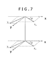
- FIG. 7 shows one example of coordinate system in a cross-dipole acquisition according to embodiments of the disclosure
- FIG. 8 shows a schematic illustration of two dipole firings D 1 and D 2 in a cross-dipole acquisition according to embodiments of the disclosure
- FIG. 9 shows a schematic illustration of two dipole firings D 1 and D 1 ′ in a single-dipole acquisition according to embodiments of the disclosure.
- FIG. 10 is a flowchart showing one example of Alford rotation processing while drilling with orthogonality error angle inversion according to the disclosure herein;
- FIG. 11 shows one example of result of Alford rotation processing while drilling with orthogonality error angle inversion according to the disclosure herein;
- FIG. 12 shows one example of coordinate system for evaluating the workflow of 2D Alford rotation according to embodiments of the disclosure
- FIG. 13 shows one example of reconstruction of anisotropy direction ⁇ for 990 cases according to embodiments of the disclosure
- FIG. 14 shows an orthogonality error angle ⁇ for any ⁇ from 0 to 90 degrees and ⁇ from 0 to ⁇ 90 degrees according to embodiments of the disclosure
- FIG. 15 shows a histogram for ⁇ angle computation error for 990 cases according to embodiments of the disclosure
- FIG. 16 shows a histogram for ⁇ angle computation error for 990 cases according to embodiments of the disclosure
- FIGS. 17A and 17B shows, respectively, an example of XX- and YY-component waveforms before and after 2D Alford Rotation according to embodiments of the disclosure
- FIGS. 18A and 18B shows, respectively, dispersion analysis results of XX- and YY-component waveforms before and after 2D Alford Rotation according to embodiments of the disclosure
- FIG. 19 is a flowchart showing one examples of data processing according to the disclosure herein.
- FIG. 20 is a block diagram of an example processing system that may execute example machine readable instructions used to implement some or all of the processes of FIGS. 7-19 to implement the example data processor of FIG. 6 .
- downhole refers to a subterranean environment, particularly in a wellbore.
- Downhole tool is used broadly to mean any tool used in a subterranean environment including, but not limited to, a logging tool, an imaging tool, an acoustic tool, a permanent monitoring tool, and a combination tool.
- the signal processing systems herein may be incorporated in tool systems such as wireline logging tools, measurement-while-drilling and logging-while-drilling tools, permanent monitoring systems, sondes, among others.
- tool systems such as wireline logging tools, measurement-while-drilling and logging-while-drilling tools, permanent monitoring systems, sondes, among others.
- wireline cable line, slickline or coiled tubing or conveyance
- any of the referenced deployment means, or any other suitable equivalent means may be used with the present disclosure without departing from the spirit and scope of the present disclosure.
- FIG. 1 illustrates an example wellsite system 1 in which the example methods, apparatus and articles of manufacture described herein to perform sonic data processing can be employed.
- the wellsite can be onshore or offshore.
- a borehole 11 is formed in subsurface formations by rotary drilling, whereas other example systems can use directional drilling.
- a drillstring 12 is suspended within the borehole 11 and has a bottom hole assembly 100 that includes a drill bit 105 at its lower end.
- the surface system includes platform and derrick assembly 10 positioned over the borehole 11 , the assembly 10 including a rotary table 16 , kelly 17 , hook 18 and rotary swivel 19 .
- the drill string 12 is suspended from a lifting gear (not shown) via the hook 18 , with the lifting gear being coupled to a mast (not shown) rising above the surface.
- An example lifting gear includes a crown block whose axis is affixed to the top of the mast, a vertically traveling block to which the hook 18 is attached, and a cable passing through the crown block and the vertically traveling block.
- one end of the cable is affixed to an anchor point, whereas the other end is affixed to a winch to raise and lower the hook 18 and the drillstring 12 coupled thereto.
- the drillstring 12 is formed of drill pipes screwed one to another.
- the drillstring 12 may be raised and lowered by turning the lifting gear with the winch.
- drill pipe raising and lowering operations require the drillstring 12 to be unhooked temporarily from the lifting gear.
- the drillstring 12 can be supported by blocking it with wedges in a conical recess of the rotary table 16 , which is mounted on a platform 21 through which the drillstring 12 passes.
- the drillstring 12 is rotated by the rotary table 16 , energized by means not shown, which engages the kelly 17 at the upper end of the drillstring 12 .
- the drillstring 12 is suspended from the hook 18 , attached to a traveling block (also not shown), through the kelly 17 and the rotary swivel 19 , which permits rotation of the drillstring 12 relative to the hook 18 .
- a top drive system could be used.
- the surface system further includes drilling fluid or mud 26 stored in a pit 27 formed at the well site.
- a pump 29 delivers the drilling fluid 26 to the interior of the drillstring 12 via a hose 20 coupled to a port in the swivel 19 , causing the drilling fluid to flow downwardly through the drillstring 12 as indicated by the directional arrow 8 .
- the drilling fluid exits the drillstring 12 via ports in the drill bit 105 , and then circulates upwardly through the annulus region between the outside of the drillstring and the wall of the borehole, as indicated by the directional arrows 9 . In this manner, the drilling fluid lubricates the drill bit 105 and carries formation cuttings up to the surface as it is returned to the pit 27 for recirculation.
- the bottom hole assembly 100 includes one or more specially-made drill collars near the drill bit 105 .
- Each such drill collar has one or more logging devices mounted on or in it, thereby allowing downhole drilling conditions and/or various characteristic properties of the geological formation (e.g., such as layers of rock or other material) intersected by the borehole 11 to be measured as the borehole 11 is deepened.
- the bottom hole assembly 100 of the illustrated example system 1 includes a logging-while-drilling (LWD) module 120 , a measuring-while-drilling (MWD) module 130 , a roto-steerable system and motor 150 , and the drill bit 105 .
- LWD logging-while-drilling
- MWD measuring-while-drilling
- the LWD module 120 is housed in a drill collar and can contain one or a plurality of logging tools. It will also be understood that more than one LWD and/or MWD module can be employed, e.g. as represented at 120 A. (References, throughout, to a module at the position of 120 can mean a module at the position of 120 A as well.)
- the LWD module 120 includes capabilities for measuring, processing, and storing information, as well as for communicating with the surface equipment.
- the LWD module 120 includes a sonic measuring device, an example of which is illustrated in FIG. 2 and described in greater detail below.
- the MWD module 130 is also housed in a drill collar and can contain one or more devices for measuring characteristics of the drillstring 12 and drill bit 105 .
- the MWD module 130 further includes an apparatus (not shown) for generating electrical power to the downhole system. This may include a mud turbine generator powered by the flow of the drilling fluid, it being understood that other power and/or battery systems may be employed.
- the MWD module 130 includes one or more of the following types of measuring devices: a weight-on-bit measuring device, a torque measuring device, a vibration measuring device, a shock measuring device, a stick slip measuring device, a direction measuring device, and an inclination measuring device.
- the wellsite system 1 also includes a logging and control unit 140 communicably coupled in any appropriate manner to the LWD module 120 / 120 A and the MWD module 130 .
- the logging and control unit 140 implements an example slowness filter processing system to process waveforms corresponding to propagating signals in a formation in accordance with the example methods, apparatus and articles of manufacture disclosed herein.
- FIG. 2 illustrates a sonic logging-while-drilling tool that can be the LWD tool 120 , or can be a part of an LWD tool suite 120 A of the type described in U.S. Pat. No. 6,308,137, incorporated herein by reference.
- an offshore rig 310 is employed, and a sonic transmitting source or array 314 is deployed near the surface of the water. Any other suitable type of uphole or downhole source or transmitter can also be provided.
- An uphole processor controls the firing of the transmitter 314 .
- the uphole equipment can also include acoustic receivers and a recorder for capturing reference signals near the source.
- the uphole equipment further includes telemetry equipment for receiving MWD signals from the downhole equipment.
- the telemetry equipment and the recorder are coupled to a processor so that recordings may be synchronized using uphole and downhole clocks.
- a downhole LWD module 300 includes at least acoustic receivers 331 and 332 , which are coupled to a signal processor so that recordings may be made of signals detected by the receivers in synchronization with the firing of the signal source.
- FIG. 3 An example receiver array 400 that may be included in the example LWD tool 120 and/or 120 A of FIGS. 1 and/or 2 is illustrated in FIG. 3 .
- the receiver array 400 of the illustrated example includes an array of thirteen ( 13 ) acoustic receivers. However, more or fewer receivers could be included in the receiver array 400 .
- each receiver in the receiver array 400 is configured to detect acoustic waves generated by one or more acoustic sources 405 and that propagate in a formation penetrated by a borehole in which the receiver array 400 is placed.
- the acoustic waveforms detected by the receivers of the receiver array 400 are staggered in time due to the spacing between the receivers.
- Signals detected (or sensed) by the receiver array 400 can be non-dispersive or dispersive.
- the waveforms determined by each receiver are substantially similar except for a time delay.
- the waveforms determined by each receiver may appear different. Examples of acoustic waveforms detected by the receiver array 400 are depicted in FIG. 4 .
- FIG. 4 depicts thirteen ( 13 ) example acoustic waveforms 500 corresponding respectively to the receivers included in the receiver array 400 of FIG. 3 .
- the acoustic waveforms illustrated in FIG. 4 are offset in time relative to each other due to the spacing between the receivers in the receiver array 400 .
- the acoustic waveforms include multiple waveform components, such a compressional waves 505 , shear waves 510 , Stoneley waves 515 , etc.
- FIG. 5 illustrates example transducer modes that can be employed by a transmitter, such as the transmitter 405 of FIG. 3 .
- the three types of excitation illustrated in FIG. 5 are monopole excitation, dipole excitation and quadrupole excitation.
- the transmitter can be modeled as a point source 605 that excites a wave that is in phase in all directions.
- the transmitter can be modeled as two-point source 610 whose components vibrate in opposition. The resulting pressure field can be viewed as pushing on one side (corresponding to a positive direction), while pulling down on the other side (corresponding to a negative direction).
- the result is a directional excitation that generates directional flexural waves (hereinafter referred to also as “borehole flexural mode”) in a formation around a borehole.
- the borehole flexural modes are dispersive, that is, their velocity varies with frequency, and travel at velocity of shear waves through the formation at low frequencies.
- the transmitter can be modeled as a four-point source 615 , of which two points located on the same diagonal are in phase, and the two on the other diagonal are out of phase.
- the quadrupole excitation generates complex quadrupole waves that are frequency dependent.
- Wireline logging employs an electrical cable to lower tools into the borehole and to transmit the data.
- logging can be performed as the tool is pulled out of the borehole.
- the data is converted downhole into electronic data, which is later transformed into a well log that can be analyzed, provided to a client, etc.
- Logging while drilling is another logging sonic logging technique.
- LWD Logging while drilling
- sensors are integrated into the drill string and the measurements are made while the well is being drilled.
- LWD measures geological parameters while the well is being drilled.
- the system 700 to acquire dipole wave data measured by a dipole acquisition in multiple firing and evaluate formation anisotropy properties based on the multiple firing dipole data may comprise a data logging system 702 , acoustic receivers (vibration sensors) 704 located in the wellbore, an acoustic source 706 of generating vibrations to be received with the receivers 704 , a data processor 710 such as a computer apparatus, and a memory 720 .
- the data logging system 702 may comprise one or more modules in the foregoing tool and tubing/cable.
- the receivers 704 such as the downhole array of multiple receivers or the DVS (Distributed Sensing System) may be installed in the foregoing tool and coupled with the data logging system 702 via the tubing/cable.
- the acoustic source 706 such as the foregoing one or more sources may be coupled with the data logging system 702 so that the generation of vibrations can be controlled.
- the acoustic waves detected with the receivers 704 may be transmitted to the data logging system 702 via the tubing/cable and the data logging system 702 may produce a data log of acoustic waves (vibrations) received at the receivers 704 .
- the data processor 710 may be coupled with the data logging system 702 via a cable or a network so as to be received the data log from the data logging system 702 .
- the data processor 710 may be implemented by one or more circuit(s), programmable processor(s), application specific integrated circuit(s) (ASIC(s)), programmable logic device(s) (PLD(s)) and/or field programmable logic device(s) (FPLD(s)), etc.
- the data log may be transferred from the data logging system 702 to the data processor 710 via a storage medium such as a USB memory, a memory card, a magnetic tape or disk, an optical disk, etc.
- the data processor 710 may be also installed within the data logging system 702 .
- the sonic data such as waveforms are temporarily or permanently stored in the memory 720 which is a tangible computer readable medium such as a memory, digital versatile disk (DVD), compact disk (CD), etc.
- Software and/or firmware including instructions for processing the sonic data are also stored in the memory.
- the data processor 710 and the memory 720 may be configured with the processing system 1200 of FIG. 20 , which is described in greater detail below.
- anisotropic properties for example, fast shear direction, fast shear slowness and slow shear slowness
- the method includes (1) Alford rotation processing while drilling for multiple firing dipole data in cross-dipole acquisition or single-dipole acquisition; (2) Alford rotation processing while drilling with orthogonality error angle inversion; (3) quality control of Alford Rotation results while drilling in the pump-off period.
- the method utilizes the advantages of LWD logging that the measurements are performed while the tool is rotating and naturally we can have multi-azimuth data.
- the disclosed method may be also applied to Wireline cross dipole data in case the two dipole firing are not orthogonal by any reason, i.e. rapid tool rotation.
- the following 2 cases, (1-1) and (1-2) are considered for acquiring sonic data from the downhole tool.
- Alford Rotation can be applied using the following relation to compensate tool rotation.
- yy ⁇ yy *cos 2 ⁇ +xx *sin 2 ⁇ +( xy+yx ⁇ )*sin ⁇ cos ⁇
- yx ⁇ yx *cos 2 ⁇ xy *sin 2 ⁇ +( xx ⁇ yy ⁇ )*sin ⁇ cos ⁇ (2)
- Equation 3 indicates the measurement is in a better condition (close to Alford geometry) when ⁇ is small.
- ⁇ s is summation over different set of firing in the interval
- ⁇ t is summation over time indices.
- Minimization angle is:
- ⁇ 0 1 4 ⁇ a ⁇ ⁇ tan ⁇ 2 ⁇ ⁇ c b + ⁇ 4 ⁇ ( ⁇ b ⁇ - b ) 2 ⁇ ⁇ b ( 5 )
- MinEne and MaxEne cross energies are obtained as follows:
- Rotated waveforms can be obtained from standard Alford Rotation equation (Equation 1). Velocity analysis can be applied to obtain fast and slow shear slowness.
- Equation 8 indicates the measurement is better condition (close to Alford geometry) when ⁇ is close to 90 degrees. Then 4 sets of waveforms can be obtained. Here cross-energy computation results from multiple firing can be also stacked in a certain depth interval. The firing pairs of good configuration can be selected. Rest of the processing can be performed as the same way as the foregoing case (1-1).
- the orthogonality error angle ⁇ is inverted simultaneously with the anisotropy direction ⁇ by 2 parameter Alford Rotation, as shown in FIG. 19 below.
- the workflow Alford rotation processing while drilling with orthogonality error angle may include two steps.
- step 1100 in FIG. 10 during logging, yy and xx from Equation 3 or Equation 4 depending on the (1-1) case: cross-dipole acquisition or (1-2) case: single dipole acquisition are computed.
- step 1102 in FIG. 10 minimum cross energy in 2D plane ( ⁇ , ⁇ ) (see FIG. 11 ), and find a minimum solution ( ⁇ , ⁇ ) to obtain the anisotropy direction ⁇ .
- D 1 and D 2 are 2 dipole firing, which are not necessarily orthogonal as shown in FIG. 12 .
- Anisotropy direction is ⁇ and the orthogonality error angle is ⁇ .
- Modeling data in horizontal well condition is generated with the following parameters, where DTc is slowness of compressional velocity, DTs is slowness of shear velocity, DTm is mud slowness and Rhom is mud density.
- FIG. 13 shows reconstruction of anisotropy direction ⁇ for 990 cases, in which angle ⁇ to anisotropy axis is plotted for any ⁇ from 0 to 90 degrees and ⁇ from 0 to ⁇ 88 degrees.
- FIG. 14 shows the comparison of ⁇ angle reconstruction with real value for 990 cases, in which orthogonality error angle ⁇ is plotted for any ⁇ from 0 to 90 ⁇ degrees and ⁇ from 0 to ⁇ 90 degrees.
- FIG. 15 shows histogram analysis of the anisotropy direction ⁇ , in which the maximum observed error do not exceed 0.6 degrees.
- FIG. 16 shows histogram analysis of orthogonality error angle ⁇ for 990 cases, in which the maximum observed error do not exceed 0.8 degrees. Even 2 degrees D 1 &D 2 inclination is processed accurately. These results show 2D Alford Rotation accurately reconstruct anisotropy direction ⁇ and orthogonality error angle ⁇ .
- FIGS. 17A and 17B shows, respectively, an example of XX- and YY-component waveforms before and after 2D Alford Rotation.
- the anisotropy direction ⁇ is 26.59 degrees and the orthogonality error angle ⁇ is ⁇ 36.82 degrees.
- FIGS. 18A and 18B shows, respectively, dispersion analysis results of XX- and YY-component waveforms before and after 2D Alford Rotation.
- the dispersion after 2D Alford Rotation is consistent with fast and slow shear slowness.
- high-quality quiet data can be acquired with exact Alford Rotation geometry. Therefore, using high-quality quiet data acquired in the pump-off period, Alford rotation processing results can be checked and a quality-control of Alford rotation results can be performed while drilling at a pipe-connection time.
- FIG. 19 is a flowchart 2000 showing one examples of data processing for dipole anisotropy in the disclosure.
- This flowchart 2000 shows an embodiment of the processing for a LWD tool.
- sonic measurements and tool angle measurements are performed under cross-dipole firing or single-dipole firing by a LWD tool in a borehole.
- the 2 parameter Alford Rotation processing is performed at step 2008 . If an orthogonality error angle of the firing data is not inverted (NO at step 2006 ), the non-orthogonal Alford Rotation processing is performed at step 2010 .
- the standard Alford Rotation processing is performed at step 2012 .
- the steps from 2002 to 2012 are repeated each depth frame in a predetermined depth range of the borehole via step 2014 .
- FIG. 20 is a block diagram of an example processing system 2100 capable of implementing the apparatus and methods disclosed herein.
- the processing system 2100 can be, for example, a server, a personal computer, a personal digital assistant (PDA), a smartphone, an Internet appliance, etc., or any other type of computing device.
- PDA personal digital assistant
- the system 2100 of the instant example includes a processor 2112 such as a general purpose programmable processor.
- the processor 2112 includes a local memory 2114 , and executes coded instructions 2116 present in the local memory 2114 and/or in another memory device.
- the processor 2112 may execute, among other things, machine-readable instructions to implement the processes represented in FIGS. 7-19 .
- the processor 2112 may be any type of processing unit, such as one or more Intel® microprocessors from the Pentium® family, the Itanium® family and/or the XScale® family, one or more microcontrollers from the ARM® and/or PIC® families of microcontrollers, etc. Of course, other processors from other families are also appropriate.
- the processor 2112 is in communication with a main memory including a volatile memory 2118 and a non-volatile memory 2120 via a bus 2122 .
- the volatile memory 2118 may be implemented by Static Random Access Memory (SRAM), Synchronous Dynamic Random Access Memory (SDRAM), Dynamic Random Access Memory (DRAM), RAMBUS Dynamic Random Access Memory (RDRAM) and/or any other type of random access memory device.
- the non-volatile memory 2120 may be implemented by flash memory and/or any other desired type of memory device. Access to the main memory 2118 , 2120 is controlled by a memory controller (not shown).
- the processing system 2100 also includes an interface circuit 2124 .
- the interface circuit 2124 may be implemented by any type of interface standard, such as an Ethernet interface, a universal serial bus (USB), and/or a third generation input/output (3GIO) interface.
- One or more input devices 2126 are connected to the interface circuit 2124 .
- the input device(s) 2126 permit a user to enter data and commands into the processor 2112 .
- the input device(s) can be implemented by, for example, a keyboard, a mouse, a touchscreen, a track-pad, a trackball, an isopoint and/or a voice recognition system.
- One or more output devices 2128 are also connected to the interface circuit 2124 .
- the output devices 2128 can be implemented, for example, by display devices (e.g., a liquid crystal display, a cathode ray tube display (CRT)), by a printer and/or by speakers.
- the interface circuit 2124 thus, includes a graphics driver card.
- the interface circuit 2124 also includes a communication device such as a modem or network interface card to facilitate exchange of data with external computers via a network (e.g., an Ethernet connection, a digital subscriber line (DSL), a telephone line, coaxial cable, a cellular telephone system, etc.).
- a network e.g., an Ethernet connection, a digital subscriber line (DSL), a telephone line, coaxial cable, a cellular telephone system, etc.
- the processing system 2100 also includes one or more mass storage devices 2130 for storing machine-readable instructions and data. Examples of such mass storage devices 2130 include floppy disk drives, hard drive disks, compact disk drives and digital versatile disk (DVD) drives. In some examples, the mass storage device 2130 may store the set of input waveforms 708 . In some examples the volatile memory 2118 may store the set of input waveforms 708 .
- the coded instructions 2132 for data processing in FIGS. 7-19 may be stored in the mass storage device 2130 , in the volatile memory 2118 , in the non-volatile memory 2120 , in the local memory 2114 and/or on a removable storage medium, such as a CD or DVD 2132 .
- the methods and or apparatus described herein may be embedded in a structure such as a processor and/or an ASIC (application specific integrated circuit).
- a structure such as a processor and/or an ASIC (application specific integrated circuit).
- a nail and a screw may not be structural equivalents in that a nail employs a cylindrical surface to secure wooden parts together, whereas a screw employs a helical surface, in the environment of fastening wooden parts, a nail and a screw may be equivalent structures. It is the express intention of the applicant not to invoke 35 U.S.C. ⁇ 112, paragraph 6 for any limitations of any of the claims herein, except for those in which the claim expressly uses the words ‘means for’ together with an associated function.
- the comparatively less expensive materials can be modified to exhibit required properties of strength and corrosion resistance sufficient to either equal or exceed current requirements for service.
Landscapes
- Physics & Mathematics (AREA)
- Life Sciences & Earth Sciences (AREA)
- Engineering & Computer Science (AREA)
- Remote Sensing (AREA)
- Acoustics & Sound (AREA)
- Environmental & Geological Engineering (AREA)
- Geology (AREA)
- General Life Sciences & Earth Sciences (AREA)
- General Physics & Mathematics (AREA)
- Geophysics (AREA)
- Geophysics And Detection Of Objects (AREA)
Abstract
Description
yy θ =yy*cos2 θ+xx*sin2θ+(xy+yx θ)*sin θ cos θ
yx θ= yx*cos2 θ−xy*sin2θ+(xx−yy θ)*sin θ cos θ (2)
yy=yy θ−(xy+yx θ)tan θ
yx=yx θ(xx−yy θ)tan θ (3)
is summation over different set of firing in the interval and
is summation over time indices. Minimization angle is:
xx θ =xx cos2 θ+yy sin2θ+(xy θ +yx)sin θ cos θ
xy θ =yx−sin2 η+xy cos2θ−(xx θ −yy)sin θ cos θ (7)
yy=xx θ−(xy+xy θ)cot θ
yx=−xy θ−(xx−xx θ)cot θ
-
- Borehole Diameter: 6.5 in
- Tool Inner Diameter/Tool Outer Diameter: 2.3 in/4.82 in
- Transmitter to 1st Receiver/Receiver to Receiver spacing: 7 ft/4 in
- DTc/DTs-fast/DTs-slow/Rhob: 65 μs/ft/108 μs/ft /152 μs/ft/2.7 g/cm3
- Mud DTm/Rhom: 284 μs/ft/2.04 g/cm3
- Modeling cases:
- θ=[0074] with step=2 degrees
- γ=[0,−88] with step=2 degrees
Claims (19)
Priority Applications (2)
| Application Number | Priority Date | Filing Date | Title |
|---|---|---|---|
| US15/333,199 US10495771B2 (en) | 2015-10-27 | 2016-10-25 | Method and system for processing dipole anisotropy |
| CA2946428A CA2946428C (en) | 2015-10-27 | 2016-10-26 | Method and system for processing dipole anisotropy |
Applications Claiming Priority (2)
| Application Number | Priority Date | Filing Date | Title |
|---|---|---|---|
| US201562247186P | 2015-10-27 | 2015-10-27 | |
| US15/333,199 US10495771B2 (en) | 2015-10-27 | 2016-10-25 | Method and system for processing dipole anisotropy |
Publications (2)
| Publication Number | Publication Date |
|---|---|
| US20170115421A1 US20170115421A1 (en) | 2017-04-27 |
| US10495771B2 true US10495771B2 (en) | 2019-12-03 |
Family
ID=58561523
Family Applications (1)
| Application Number | Title | Priority Date | Filing Date |
|---|---|---|---|
| US15/333,199 Active 2037-01-05 US10495771B2 (en) | 2015-10-27 | 2016-10-25 | Method and system for processing dipole anisotropy |
Country Status (2)
| Country | Link |
|---|---|
| US (1) | US10495771B2 (en) |
| CA (1) | CA2946428C (en) |
Families Citing this family (2)
| Publication number | Priority date | Publication date | Assignee | Title |
|---|---|---|---|---|
| US10808526B2 (en) * | 2018-10-16 | 2020-10-20 | Halliburton Energy Services, Inc. | Transmitter and receiver interface for downhole logging |
| CN112539056B (en) * | 2019-09-05 | 2022-11-25 | 中国石油化工股份有限公司 | Multi-dimensional underground imaging feature extraction method and imaging device |
Citations (6)
| Publication number | Priority date | Publication date | Assignee | Title |
|---|---|---|---|---|
| US20050000688A1 (en) * | 2001-09-21 | 2005-01-06 | Chaur-Jian Hsu | Quadrupole acoustic shear wave logging while drilling |
| US20060235618A1 (en) * | 2005-03-31 | 2006-10-19 | Schlumberger Technology Corporation | Pump off measurements for quality control and wellbore stability prediction |
| US20070030761A1 (en) * | 2005-08-04 | 2007-02-08 | Donald J A | Method for characterizing shear wave formation anisotropy |
| US20070268782A1 (en) * | 2006-03-07 | 2007-11-22 | Schlumberger Technology Corporation, Incorporated In The State Of Texas | Anisotropy measurement while drilling |
| US20130064039A1 (en) * | 2011-09-14 | 2013-03-14 | Jahir Pabon | Acoustic logging while drilling tool with active control of source orientation |
| US20150263435A1 (en) * | 2014-03-17 | 2015-09-17 | Quintel Technology Limited | Compact antenna array using virtual rotation of radiating vectors |
Family Cites Families (2)
| Publication number | Priority date | Publication date | Assignee | Title |
|---|---|---|---|---|
| JP2004214459A (en) * | 2003-01-06 | 2004-07-29 | Sony Corp | Nonvolatile magnetic memory and its fabricating process |
| US20050000068A1 (en) * | 2003-06-16 | 2005-01-06 | Waszak John P. | Apparatus for fastening items on a mantle or shelf |
-
2016
- 2016-10-25 US US15/333,199 patent/US10495771B2/en active Active
- 2016-10-26 CA CA2946428A patent/CA2946428C/en active Active
Patent Citations (6)
| Publication number | Priority date | Publication date | Assignee | Title |
|---|---|---|---|---|
| US20050000688A1 (en) * | 2001-09-21 | 2005-01-06 | Chaur-Jian Hsu | Quadrupole acoustic shear wave logging while drilling |
| US20060235618A1 (en) * | 2005-03-31 | 2006-10-19 | Schlumberger Technology Corporation | Pump off measurements for quality control and wellbore stability prediction |
| US20070030761A1 (en) * | 2005-08-04 | 2007-02-08 | Donald J A | Method for characterizing shear wave formation anisotropy |
| US20070268782A1 (en) * | 2006-03-07 | 2007-11-22 | Schlumberger Technology Corporation, Incorporated In The State Of Texas | Anisotropy measurement while drilling |
| US20130064039A1 (en) * | 2011-09-14 | 2013-03-14 | Jahir Pabon | Acoustic logging while drilling tool with active control of source orientation |
| US20150263435A1 (en) * | 2014-03-17 | 2015-09-17 | Quintel Technology Limited | Compact antenna array using virtual rotation of radiating vectors |
Non-Patent Citations (4)
| Title |
|---|
| Alford, R. M., "Shear Data in the Presence of Azimuthal Anisotropy: Dilley, Texas", Expanded Abstracts, 56th SEG Annual International Meeting and Exposition, Houston, Texas, USA, Nov. 2-6, 1986, pp. 476-479. |
| B. Nolte and A. C. H. Cheng, "Estimation of Nonorthogonal Shear Wave Polarizations and Shear Wave Velocities From Four-Component Dipole Logs", 1996, ERL Industry Consortia Technical Reports. |
| S. Bose, "Performance bounds on shear anisotropy azimuth estimation using borehole sonic logging tools", Sensor Array and Multichannel Signal Processing Workshop Proceedings, 2002. |
| X. Zeng. and C. Macbeth, "Algebraic Processing Technique for Estimating Shear-Wave Splitting in Near-Offset VSP Data : Theory", Geophysical Prospecting, 41(8), pp. 1033-1066, Nov. 1993. |
Also Published As
| Publication number | Publication date |
|---|---|
| CA2946428C (en) | 2024-01-09 |
| US20170115421A1 (en) | 2017-04-27 |
| CA2946428A1 (en) | 2017-04-27 |
Similar Documents
| Publication | Publication Date | Title |
|---|---|---|
| US11835673B2 (en) | Methods and systems for determining fast and slow shear directions in an anisotropic formation using a logging while drilling tool | |
| US9494705B2 (en) | Cased-hole radial profiling of shear parameters from sonic measurements | |
| US11015443B2 (en) | Estimation of horizontal stresses and nonlinear constants in anisotropic formations such as interbedded carbonate layers in organic-shale reservoirs | |
| US8117014B2 (en) | Methods to estimate subsurface deviatoric stress characteristics from borehole sonic log anisotropy directions and image log failure directions | |
| US20140086009A1 (en) | Methods and Apparatus for Waveform Processing | |
| US8848484B2 (en) | Filtering acoustic waveforms in downhole environments | |
| US10379247B2 (en) | Method and system for estimating formation slowness | |
| CN103827696A (en) | Multi-well anisotropy inversion | |
| US10890682B2 (en) | Method and system for imaging dipping structures | |
| US10613242B2 (en) | Azimuthal determination of subterranean acoustic reflectors | |
| US11002871B2 (en) | Method and system for processing sonic data acquired with a downhole tool | |
| US8730763B2 (en) | Methods and apparatus to optimize parameters in a downhole environment | |
| US10392934B2 (en) | Method and apparatus for processing waveforms | |
| US10495771B2 (en) | Method and system for processing dipole anisotropy | |
| US20130070560A1 (en) | Arranging Source-Receiver Orientations to Reduce High-Order Modes in Acoustic Monopole Logging | |
| EP2672293A2 (en) | Methods and Apparatus for Modeling Formations | |
| US9110192B2 (en) | Methods and apparatus to identify layer boundaries in subterranean formations | |
| US11422279B2 (en) | Method and system for estimating borehole condition using stoneley measurement | |
| US12013510B2 (en) | Multi-resolution based method for automated acoustic log depth tracking | |
| US9581716B2 (en) | Methods and apparatus for estimating borehole mud slownesses | |
| US20140116726A1 (en) | Downhole Sensor and Method of Coupling Same to A Borehole Wall | |
| CN115075805A (en) | Method and device for determining formation anisotropy |
Legal Events
| Date | Code | Title | Description |
|---|---|---|---|
| AS | Assignment |
Owner name: SCHLUMBERGER TECHNOLOGY CORPORATION, TEXAS Free format text: ASSIGNMENT OF ASSIGNORS INTEREST;ASSIGNORS:ENDO, TAKESHI;VALERO, HENRI-PIERRE;SYRESIN, DENIS;SIGNING DATES FROM 20161215 TO 20170127;REEL/FRAME:041127/0144 |
|
| STPP | Information on status: patent application and granting procedure in general |
Free format text: FINAL REJECTION MAILED |
|
| STPP | Information on status: patent application and granting procedure in general |
Free format text: DOCKETED NEW CASE - READY FOR EXAMINATION |
|
| STPP | Information on status: patent application and granting procedure in general |
Free format text: NOTICE OF ALLOWANCE MAILED -- APPLICATION RECEIVED IN OFFICE OF PUBLICATIONS |
|
| STPP | Information on status: patent application and granting procedure in general |
Free format text: PUBLICATIONS -- ISSUE FEE PAYMENT VERIFIED |
|
| STCF | Information on status: patent grant |
Free format text: PATENTED CASE |
|
| MAFP | Maintenance fee payment |
Free format text: PAYMENT OF MAINTENANCE FEE, 4TH YEAR, LARGE ENTITY (ORIGINAL EVENT CODE: M1551); ENTITY STATUS OF PATENT OWNER: LARGE ENTITY Year of fee payment: 4 |