US10495131B2 - Blind nut, a blind nut assembly and mounting structure thereof - Google Patents
Blind nut, a blind nut assembly and mounting structure thereof Download PDFInfo
- Publication number
- US10495131B2 US10495131B2 US15/654,958 US201715654958A US10495131B2 US 10495131 B2 US10495131 B2 US 10495131B2 US 201715654958 A US201715654958 A US 201715654958A US 10495131 B2 US10495131 B2 US 10495131B2
- Authority
- US
- United States
- Prior art keywords
- nut
- collar
- bolt
- cylindrical member
- polygonal
- Prior art date
- Legal status (The legal status is an assumption and is not a legal conclusion. Google has not performed a legal analysis and makes no representation as to the accuracy of the status listed.)
- Expired - Fee Related, expires
Links
- 239000000463 material Substances 0.000 claims description 11
- 238000003780 insertion Methods 0.000 description 5
- 230000037431 insertion Effects 0.000 description 5
- 238000012986 modification Methods 0.000 description 5
- 230000004048 modification Effects 0.000 description 5
- 230000002093 peripheral effect Effects 0.000 description 4
- 230000000717 retained effect Effects 0.000 description 3
- 229910001209 Low-carbon steel Inorganic materials 0.000 description 1
- 230000002159 abnormal effect Effects 0.000 description 1
- XAGFODPZIPBFFR-UHFFFAOYSA-N aluminium Chemical compound [Al] XAGFODPZIPBFFR-UHFFFAOYSA-N 0.000 description 1
- 229910052782 aluminium Inorganic materials 0.000 description 1
- 230000004323 axial length Effects 0.000 description 1
- 230000007423 decrease Effects 0.000 description 1
- 230000003247 decreasing effect Effects 0.000 description 1
- 230000000694 effects Effects 0.000 description 1
- 230000001788 irregular Effects 0.000 description 1
- 230000013011 mating Effects 0.000 description 1
- 238000000034 method Methods 0.000 description 1
- 230000003014 reinforcing effect Effects 0.000 description 1
Images


Classifications
-
- F—MECHANICAL ENGINEERING; LIGHTING; HEATING; WEAPONS; BLASTING
- F16—ENGINEERING ELEMENTS AND UNITS; GENERAL MEASURES FOR PRODUCING AND MAINTAINING EFFECTIVE FUNCTIONING OF MACHINES OR INSTALLATIONS; THERMAL INSULATION IN GENERAL
- F16B—DEVICES FOR FASTENING OR SECURING CONSTRUCTIONAL ELEMENTS OR MACHINE PARTS TOGETHER, e.g. NAILS, BOLTS, CIRCLIPS, CLAMPS, CLIPS OR WEDGES; JOINTS OR JOINTING
- F16B19/00—Bolts without screw-thread; Pins, including deformable elements; Rivets
- F16B19/02—Bolts or sleeves for positioning of machine parts, e.g. notched taper pins, fitting pins, sleeves, eccentric positioning rings
-
- F—MECHANICAL ENGINEERING; LIGHTING; HEATING; WEAPONS; BLASTING
- F16—ENGINEERING ELEMENTS AND UNITS; GENERAL MEASURES FOR PRODUCING AND MAINTAINING EFFECTIVE FUNCTIONING OF MACHINES OR INSTALLATIONS; THERMAL INSULATION IN GENERAL
- F16B—DEVICES FOR FASTENING OR SECURING CONSTRUCTIONAL ELEMENTS OR MACHINE PARTS TOGETHER, e.g. NAILS, BOLTS, CIRCLIPS, CLAMPS, CLIPS OR WEDGES; JOINTS OR JOINTING
- F16B37/00—Nuts or like thread-engaging members
- F16B37/04—Devices for fastening nuts to surfaces, e.g. sheets, plates
- F16B37/041—Releasable devices
- F16B37/042—Releasable devices locking by rotation
-
- F—MECHANICAL ENGINEERING; LIGHTING; HEATING; WEAPONS; BLASTING
- F16—ENGINEERING ELEMENTS AND UNITS; GENERAL MEASURES FOR PRODUCING AND MAINTAINING EFFECTIVE FUNCTIONING OF MACHINES OR INSTALLATIONS; THERMAL INSULATION IN GENERAL
- F16B—DEVICES FOR FASTENING OR SECURING CONSTRUCTIONAL ELEMENTS OR MACHINE PARTS TOGETHER, e.g. NAILS, BOLTS, CIRCLIPS, CLAMPS, CLIPS OR WEDGES; JOINTS OR JOINTING
- F16B37/00—Nuts or like thread-engaging members
- F16B37/04—Devices for fastening nuts to surfaces, e.g. sheets, plates
- F16B37/06—Devices for fastening nuts to surfaces, e.g. sheets, plates by means of welding or riveting
- F16B37/062—Devices for fastening nuts to surfaces, e.g. sheets, plates by means of welding or riveting by means of riveting
- F16B37/065—Devices for fastening nuts to surfaces, e.g. sheets, plates by means of welding or riveting by means of riveting by deforming the material of the nut
- F16B37/067—Devices for fastening nuts to surfaces, e.g. sheets, plates by means of welding or riveting by means of riveting by deforming the material of the nut the material of the nut being deformed by a threaded member generating axial movement of the threaded part of the nut, e.g. blind rivet type
-
- F—MECHANICAL ENGINEERING; LIGHTING; HEATING; WEAPONS; BLASTING
- F16—ENGINEERING ELEMENTS AND UNITS; GENERAL MEASURES FOR PRODUCING AND MAINTAINING EFFECTIVE FUNCTIONING OF MACHINES OR INSTALLATIONS; THERMAL INSULATION IN GENERAL
- F16B—DEVICES FOR FASTENING OR SECURING CONSTRUCTIONAL ELEMENTS OR MACHINE PARTS TOGETHER, e.g. NAILS, BOLTS, CIRCLIPS, CLAMPS, CLIPS OR WEDGES; JOINTS OR JOINTING
- F16B39/00—Locking of screws, bolts or nuts
- F16B39/02—Locking of screws, bolts or nuts in which the locking takes place after screwing down
- F16B39/08—Locking of screws, bolts or nuts in which the locking takes place after screwing down with a cap interacting with the nut, connected to the bolt by a pin or cotter pin
-
- F—MECHANICAL ENGINEERING; LIGHTING; HEATING; WEAPONS; BLASTING
- F16—ENGINEERING ELEMENTS AND UNITS; GENERAL MEASURES FOR PRODUCING AND MAINTAINING EFFECTIVE FUNCTIONING OF MACHINES OR INSTALLATIONS; THERMAL INSULATION IN GENERAL
- F16B—DEVICES FOR FASTENING OR SECURING CONSTRUCTIONAL ELEMENTS OR MACHINE PARTS TOGETHER, e.g. NAILS, BOLTS, CIRCLIPS, CLAMPS, CLIPS OR WEDGES; JOINTS OR JOINTING
- F16B39/00—Locking of screws, bolts or nuts
- F16B39/02—Locking of screws, bolts or nuts in which the locking takes place after screwing down
- F16B39/10—Locking of screws, bolts or nuts in which the locking takes place after screwing down by a plate, spring, wire or ring immovable with regard to the bolt or object and mainly perpendicular to the axis of the bolt
-
- F—MECHANICAL ENGINEERING; LIGHTING; HEATING; WEAPONS; BLASTING
- F16—ENGINEERING ELEMENTS AND UNITS; GENERAL MEASURES FOR PRODUCING AND MAINTAINING EFFECTIVE FUNCTIONING OF MACHINES OR INSTALLATIONS; THERMAL INSULATION IN GENERAL
- F16B—DEVICES FOR FASTENING OR SECURING CONSTRUCTIONAL ELEMENTS OR MACHINE PARTS TOGETHER, e.g. NAILS, BOLTS, CIRCLIPS, CLAMPS, CLIPS OR WEDGES; JOINTS OR JOINTING
- F16B39/00—Locking of screws, bolts or nuts
- F16B39/02—Locking of screws, bolts or nuts in which the locking takes place after screwing down
- F16B39/12—Locking of screws, bolts or nuts in which the locking takes place after screwing down by means of locknuts
- F16B39/122—Locking of screws, bolts or nuts in which the locking takes place after screwing down by means of locknuts foreseen with mating surfaces inclined, i.e. not normal, to the bolt axis
- F16B39/124—Locking of screws, bolts or nuts in which the locking takes place after screwing down by means of locknuts foreseen with mating surfaces inclined, i.e. not normal, to the bolt axis with helically inclined mating surfaces
-
- F—MECHANICAL ENGINEERING; LIGHTING; HEATING; WEAPONS; BLASTING
- F16—ENGINEERING ELEMENTS AND UNITS; GENERAL MEASURES FOR PRODUCING AND MAINTAINING EFFECTIVE FUNCTIONING OF MACHINES OR INSTALLATIONS; THERMAL INSULATION IN GENERAL
- F16B—DEVICES FOR FASTENING OR SECURING CONSTRUCTIONAL ELEMENTS OR MACHINE PARTS TOGETHER, e.g. NAILS, BOLTS, CIRCLIPS, CLAMPS, CLIPS OR WEDGES; JOINTS OR JOINTING
- F16B39/00—Locking of screws, bolts or nuts
- F16B39/22—Locking of screws, bolts or nuts in which the locking takes place during screwing down or tightening
- F16B39/24—Locking of screws, bolts or nuts in which the locking takes place during screwing down or tightening by means of washers, spring washers, or resilient plates that lock against the object
- F16B39/26—Locking of screws, bolts or nuts in which the locking takes place during screwing down or tightening by means of washers, spring washers, or resilient plates that lock against the object with spring washers fastened to the nut or bolt-head
-
- F—MECHANICAL ENGINEERING; LIGHTING; HEATING; WEAPONS; BLASTING
- F16—ENGINEERING ELEMENTS AND UNITS; GENERAL MEASURES FOR PRODUCING AND MAINTAINING EFFECTIVE FUNCTIONING OF MACHINES OR INSTALLATIONS; THERMAL INSULATION IN GENERAL
- F16B—DEVICES FOR FASTENING OR SECURING CONSTRUCTIONAL ELEMENTS OR MACHINE PARTS TOGETHER, e.g. NAILS, BOLTS, CIRCLIPS, CLAMPS, CLIPS OR WEDGES; JOINTS OR JOINTING
- F16B33/00—Features common to bolt and nut
- F16B33/002—Means for preventing rotation of screw-threaded elements
Definitions
- the present invention relates to a blind nut and a mounting structure thereof, and in particular to a blind nut which can be mounted or removed in one step, as well as a mounting structure thereof which is mounted by such a blind but as stated above.
- a blind nut consists of a female screw member with female screws formed on the inner surface thereof, a hollow tubular member adjacent to the female screw member, and a flange provided with an opening on one edge of the tubular member.
- the tubular member of the blind nut is inserted through the mounting hole of the mounted member to cause the flange in contact with the surface of the mounted member; in this state, plastic deformation is performed by utilizing a tightening tool so as to enlarge the diameter of the tubular member, and the mounted member is caused to be sandwiched between the deformed tubular member and the flange. In this manner, the blind nut is fixated onto the mounted member.
- the male screw provided on a bolt is caused to be engaged with the female screw on the blind nut, which has been fixated onto the mounted member. Then another mounting member can be mounted.
- the blind nut is utilized, one side of the mounted member is worked on. Therefore, the blind nut can be utilized to tighten a mounting member such as decorative items and the like onto a member of which the rear side is not accessible (for example, a mounted member such as a panel, and the like).
- the blind nut is caulked to the mounted member, by utilizing a dedicated tool, on the side (blind side) opposite from the insertion side; and then the mounting member is bolted on the insertion side (working side) with a bolt.
- two steps have been needed.
- Patent Literature 1 relates to such a blind nut as stated above and discloses a caulking nut (blind nut) which comprises a primary nut and a secondary nut.
- the primary nut is constituted in a manner so that a thick walled-opening member is formed on the upper end of the thin cylindrical member having an inner hole.
- the thick walled-opening member has a male screw on the outer periphery thereof and has a hole of which the inner diameter is smaller than the inner hole of the thin cylindrical member.
- On the lower end of the thin cylindrical member a female screw of which the inner shape is smaller than the inner hole thereof is formed.
- the secondary nut has a female screw which is capable of being engaged with the male screw provided on the thick walled-opening member, and it is constituted to take a polygonal shape.
- the caulking nut In order to mount the caulking nut, the caulking nut is inserted into the mounting hole of the plate (mounted member), with the female screw provided on the secondary nut engaged with the male screw provided on one end of the primary nut.
- the cylindrical member of the primary nut is bended to the outer side of the radius direction to form a protrusion (expanded radius member), which causes the plate to be sandwiched between the secondary nut and the protrusion of the primary nut.
- a bolt is caused to pass through the mounting hole of the mounting member to be engaged with the female screw of the primary nut.
- the mounting member such as a frame and the like can be mounted.
- the secondary nut When not in use, the secondary nut is loosened to remove it from the primary nut; and the primary nut is pulled out through the mounting hole on the plate. Thus, the caulking nut can be removed.
- the blind nut is caulked by utilizing the caulking tool onto the mounted member on the side opposite from the insertion side, and then the mounting member on the insertion side is screwed by utilizing a bolt. Therefore, the operations need to be conducted in these 2 steps.
- Another blind rivet is available which can be mounted in one step by utilizing commercially-available drills and tools.
- the flange is constituted as a separate body, and thus the blind rivet can be removed after it is mounted.
- the strength in the circumferential direction of the enlarged diameter member to be buckled decreases, which may deform the enlarged diameter member into an abnormally deformed shape due to the stress resulting from tightening the screw.
- Patent Literature 2 relates to such a blind rivet as stated above and discloses a caulking nut (blind nut) which can be removed after it is mounted; it comprises a primary nut and a washer.
- a mouth member having an uneven outer periphery is formed at the upper end of a cylindrical member having a thin inner hole.
- the mouth member On the lower end of the cylindrical member, the mouth member has a mating hole which can be mated with the mouth member and has an irregular shape; the outer periphery thereof is constituted into a hexagonal shape.
- the caulking nut In order to mount the caulking nut, the caulking nut is inserted into the mounting hole on the plate, with the washer mated with the mouth member provided on the primary nut.
- a tightening bolt is inserted into the inner hole of the primary nut from the upper direction; the rotary shaft of the caulking tool is mated with the recess of the tightening bolt; and the detent is caused to be engaged with the outer periphery of the hexagonal washer to prevent the washer from rotating around.
- the tightening bolt When not in use, the tightening bolt is caused to be reversely rotated to remove [the caulking nut] from the primary nut, with the washer retained by the detent to prevent the washer from rotating around. Subsequently, when the washer is pulled out of the upper end of the primary nut, the primary nut can be removed from the plate.
- the caulking nut disclosed in Patent Literature 2 is capable of fastening two plates in one bolt-tightening step through the use of the caulking tool by forming a protruding member. Moreover, when the tightening bolt is reversely rotated, and the washer is removed, the caulking nut can be removed. However, when the tightening bolt is mounted to buckle the cylindrical member, force in the circumferential direction is applied to the cylindrical member about the center axis thereof. Meanwhile, in the caulking nut of Patent Literature 2, the washer is constituted as a separate member so as to be removable, the strength against the force in the circumferential direction is decreased. When the tightening bolt is rotated to buckle the cylindrical member, the cylindrical member may be abnormally deformed in a twisted manner. Wherefore, the thickness of the upper portion of the cylindrical member has had to be thick.
- the object of the present invention is to provide a blind nut which can be mounted in one step simply by utilizing commercially-available rotating tools, such as an electric drill, and the like, which can be removed, and of which the expanded diameter member is not abnormally deformed.
- the blind nut of the present invention comprises a bush consisting of a cylindrical collar, which has a polygonal shape on the outer surface thereof, and a flange, which has a polygonal shape on the outer surface; and a nut consisting of a female screw member and a nut cylindrical member, of which the thickness is thinner.
- the nut cylindrical member is supported by the collar of the bush from the inside thereof, and the nut cylindrical member appropriately expands to form an expanded diameter member.
- Blind nut comprising a bush consisting of a short cylindrical collar, which has a polygonal outer surface on the outer surface thereof, and a flange, which is formed on one end of the collar;
- a nut body consisting of a cylindrical female screw member, on which a female screw to be mated with a male screw on a bolt is formed; and a nut cylindrical member, which is formed adjacent to the female screw member, which is a polygonal inner surface on the inner surface thereof aligning with the polygonal outer surface of the collar, and which has a wall thickness that is thinner than the female screw member.
- the collar of the bush When the collar of the bush has the polygonal outer surface thereof, and when the nut cylindrical member of the nut has the polygonal inner surface thereof which aligns the polygonal outer surface, the collar of the bush is inserted into the inside of the nut cylindrical member of the nut so that the collar supports the nut cylindrical member from the inside, and the nut and the bush can be retained so as not to be mutually rotated.
- a bolt head hole of which the cross-sectional surface is polygonal be formed on the central portion of the bolt head of the bolt. It is desirable that the cross-sectional surface be hexagonal. If the bolt head hole having the polygonal cross-sectional surface is formed, it becomes possible to insert a tool into the bolt head hole to rotate the bolt. It is desirable that, on the flange of the bush, a flange concave member for accommodating the bolt head be formed. If the flange concave member is formed on the flange, it becomes possible to accommodate the bolt head.
- a nut head having an outer diameter larger than the outer diameter of the nut cylindrical member be formed on one end of the nut cylindrical member.
- the thick nut head is formed on one end of the nut cylindrical member, when the bolt is screwed in to buckle the nut cylindrical member, it becomes possible to prevent nut cylindrical member from being deformed in a twisted manner in the circumferential direction.
- the outer surface of the flange of the bush is desirably polygonal. If the outer surface of the flange of the bush is polygonal, it becomes possible to provide support to it so that it is not rotated by tools, such as a wrench, and the like.
- the upper surface and the lower surface of the flange of the bush be inclined downward from the central portion to the periphery. If the upper surface and the lower surface of the flange of the bush are inclined downward from the central portion to the periphery, when the blind nut is mounted onto the mounted member, the flange bends, and this creates stable axial force, which retains the mounted member.
- the outer surface of the nut cylindrical member be a polygonal outer surface having the same number of polygonal corners as the polygonal inner surface of the nut cylindrical member; the thickness of the nut cylindrical member is desirably constant in the circumferential direction. If the thickness of the nut cylindrical member is constant, when the nut cylindrical member is buckled to be mounted, the nut cylindrical member becomes capable of expanding evenly.
- the polygonal outer surface of the collar and the polygonal inner surface of the nut be hexagonal.
- the bush is preferably formed with a material that is harder than the nut. If the bush is preferably formed with a material that is harder than the nut, when the nut cylindrical member of the nut is buckled, the bush is not deformed, which makes it possible for the bush to support the nut cylindrical member from the inside thereof in a firmer manner.
- Blind nut assembly which is an assembly of the bush, nut, and bolt of the blind nut
- the polygonal outer surface of the collar of the bush aligns with the polygonal inner surface of the nut cylindrical member of the nut
- the collar of the bush is accommodated within the nut so as not to be rotated
- the male screw of the bolt is engaged with the female screw of the nut.
- the area surrounding the mounting hole of the mounted member and the area surrounding the mounting hole of the mounting member are sandwiched between the lower surface of the flange of the bush and the expanded diameter member where the nut cylindrical member of the nut is expanded.
- the expanded diameter member has a strength level at which it capable of securely tightening the mounted member and the mounting member.
- Blind nut comprising:
- a bush having a short cylindrical collar, which has a polygonal outer surface on the outer surface thereof, and
- the nut body has a female screw member, on which a female screw to be mated with a male screw of the axial member of a bolt is formed, and
- a nut cylindrical member which is formed adjacent to the female screw member, has a polygonal inner surface on the inner surface thereof aligning with the polygonal outer surface of the collar, the outer surface of which is a polygonal outer surface having the same number of polygonal corners as the polygonal inner surface, and a wall thickness that is thinner than the female screw member.
- the bush takes a short cylindrical shape, consists of the collar having the polygonal outer surface and has no flange, the shape of the bush is simple, and thus such bush as the above can be manufactured at low cost.
- the cross-sectional surface of the bolt head of the bolt is desirably hexagonal. If the cross-sectional surface of the bolt head is hexagonal, it becomes possible to rotate the bolt with ease by utilizing tools such as a wrench.
- the collar is desirably formed with a material harder than the nut. If the collar is formed with a material harder than the nut, when the nut cylindrical member of the nut buckles to form the expanded diameter member, the collar is not deformed, and it is capable of firmly supporting the nut cylindrical member from the inside thereof.
- Blind nut assembly which is an assembly of the bush, nut and bolt of the blind nut
- the collar is accommodated within the nut so as not to be rotated
- the lower surface of the bolt head of the bolt is in contact with the upper surface of the nut cylindrical member of the nut body
- the male screw of the bolt is mated with the female screw of the nut.
- the area surrounding the mounting hole of the mounted member and the area surrounding the mounting hole of the mounting member are sandwiched between the lower surface of the bolt head of the bolt and the expanded diameter member where the nut cylindrical member of the nut is expanded.
- Blind nut assembly which is an assembly of the bush, nut, bolt, and washer of the blind nut
- the collar is accommodated within the nut so as not to be rotated
- the lower surface of washer is in contact with the upper surface of the nut cylindrical member of the nut body
- the male screw of the bolt is mated with the female screw of the nut body.
- the utilized washer have an inner diameter that is larger than the axial member of the bolt, and an outer diameter that is larger than the nut head of the nut. If the washer utilized has an inner diameter that is larger than the axial member of the bolt and an outer diameter that is larger than the nut head of the nut, it becomes possible to screw in the bolt in a smooth manner.
- the area surrounding the mounting hole of the mounted member and the area surrounding the mounting hole of the mounting member are sandwiched between the lower surface of the washer and the expanded diameter member where the nut cylindrical member of the nut is expanded.
- the mounting hole of the mounted member be polygonal, having the same number of polygonal corners as the polygonal outer surface of the collar and the polygonal inner surface of the nut cylindrical member. If the mounting hole of the mounted member is polygonal, having the same number of polygonal corners as the polygonal outer surface of the collar and the polygonal inner surface of the nut cylindrical member, when the blind nut is mounted, it becomes possible to support the nut cylindrical member so as not to be rotated, which makes it unnecessary to retain the bush so as not to be rotated.
- the polygonal outer surface of the collar, the polygonal inner surface of the nut cylindrical member, and the mounting hole of the mounted member be square. If the polygonal outer surface of the collar, the polygonal inner surface of the nut cylindrical member, and the mounting hole of the mounted member are square, the effects of preventing the rotations are well exhibited.
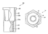
- FIG. 1 is an exploded perspective view of a blind nut according to a first embodiment of the present invention.
- FIG. 2 is a top view of the bush of the blind nut of FIG. 1 .
- FIG. 3 is a front view showing a portion of the bush of FIG. 2 as a cross section.
- FIG. 4 is a bottom view of the bush of FIG. 2 .
- FIG. 5 is a top view of the nut body of the blind nut of FIG. 1 .
- FIG. 6 is a front view showing a portion of the nut body of FIG. 5 as a cross section.
- FIG. 7 is a bottom view of the nut body of FIG. 5 .
- FIG. 8 is a top view of a plain nut assembly with blind nut members assembled of FIG. 1 .
- FIG. 9 is a front view showing a portion of the blind nut assembly of FIG. 8 as a cross section.
- FIG. 10 is a bottom view of the blind nut assembly of FIG. 8 .
- FIG. 11 is a front view showing a portion of the state where the mounted member and the mounting member are fastened by the blind nut assembly of FIG. 8 as a cross section.
- FIG. 12 is a front view showing a portion of the state wherein the mounted member and the mounting member are fastened by the blind nut assembly of FIG. 8 as a cross section.
- FIG. 13 is a top view of a modification of the bushing.
- FIG. 14 is a front view showing a portion of a modification of the bush of FIG. 13 as a cross section.
- FIG. 15 is a bottom view of a modification of the bush of FIG. 13 .
- FIG. 16 is an exploded perspective view of a blind nut according to a second embodiment of the present invention.
- FIG. 17 is a top view of the collar of the blind nut of FIG. 16 .
- FIG. 18 is a front view showing a portion of the collar of FIG. 17 as a cross section.
- FIG. 19 is a top view of the nut body of the blind nut of FIG. 16 .
- FIG. 20 is a front view of the nut body of FIG. 19 .
- FIG. 21 is a bottom view of the nut body of FIG. 19 .
- FIG. 1 is an exploded perspective view of a blind nut 1 , a bolt 10 , a mounted member 41 , and a mounting member 42 according to the first embodiment.
- FIG. 1 is an exploded perspective view of a blind nut 1 , a bolt 10 , a mounted member 41 and a mounting member 42 according to the first embodiment.
- the blind nut 1 is provided with a bush 20 and a nut body 30 .
- the bolt 10 has a shaft member 11 having a male screw 12 and a bolt head member 14 on the upper portion thereof.
- a bolt head hole 15 having a hexagonal cross section is formed in the bolt head member 14 ; a bolt head hole 15 of a hexagonal cross section shape is formed on the bolt head member 14 , so that the bolt can be rotated by a tool such as a commercially-available hexagonal wrench.
- the bush 20 has a short tubular collar 21 and an upper flange 24 thereof.
- the nut body 30 has a female screw member 31 and a nut cylindrical member 33 ; a nut head member 35 is formed on the upper portion of the nut cylindrical member 33 .
- An attachment hole 43 having a circular cross section is formed on the mounted member 41 .
- a mounting hole 44 having a circular cross section is formed in the mounting member 42 .
- the collar 21 of the bush 20 is inserted into the nut cylindrical member 33 of the nut body 30 , the shaft member 11 of the bolt 10 is inserted into therein, the male screw 12 of the bolt 10 is screwably mounted into the female screw 32 of the female screw member 31 of the nut body 30 to form a blind nut assembly 1 a.
- the blind nut assembly 1 a is inserted into the attachment holes 43 , 44 of the mounted member 41 and the mounting member 42 ; when the male screw 12 of the bolt 10 is further screwed into the female screw 32 of the nut body 30 , the nut cylindrical member 33 buckles to form an enlarged diameter member 33 d , and between the flange 24 and the enlarged diameter member 33 d , the mounted member 41 and the mounting member 42 are fastened.
- FIGS. 2-4 show the bush 20
- FIGS. 5-7 show the nut body 30
- FIGS. 8-10 show the blind nut assembly 1 a in which the bolt 10 , the bush 20 and the nut body 30 are combined.
- FIGS. 11 and 12 are cross sectional views of the blind nut body 1 a in a state where the mounted member 41 and the mounting member 42 are fastened. In the description of the present specification, the description will be done with the upper direction of FIG. 1 as the top.
- the bolt 10 is a commercially-available product and will now be described with reference to the exploded perspective view of FIG. 1 .
- the bolt 10 is formed of a rigid material that is hard to deform, and has a shaft member 11 having a male screw 12 of an elongated columnar shape, and a bolt head member 14 of a diameter larger than that of the shaft member 11 on the upper portion.
- An outer peripheral portion of the bolt head member 14 is circular, and a bolt head hole 15 of a hexagonal cross section shape is formed in the upper central portion of the bolt head member 14 .
- a tip portion of a commercially-available tool such as a hexagonal wrench wherein the cross section is of a hexagonal shape is inserted into the bolt head hole 15 so that the bolt 10 can be rotated.
- a hexagonal outer peripheral portion may be formed on the bolt head member 14 , and this portion may be rotated by a wrench, or the like.
- FIG. 2 is a top view of the bush 20
- FIG. 3 is a front view in which a portion is rendered as a cross section
- FIG. 4 is a bottom view.
- the bush 20 is a member for reinforcing the nut body 30 from the inside when a later-described nut body 30 buckles, and is made of a material harder than the nut body 30 .
- the bush 20 is axially symmetrical about the central axis as a whole.
- the bush 20 has a collar 21 with a short tube at one end and a flange 24 at the other end.
- the collar outer surface 21 b of the collar 21 is a polygonal outer surface having a substantially hexagonal cross section, and the vertex is chamfered.
- a collar hole 22 of a circular cross section shape is formed along the central axis of the collar 21 .
- the distance between the two opposing outer surfaces of the flange 24 is greater than the distance (maximum diameter) between the apexes of the collar 21 .
- the cross section of the outer surfaces of the flange 24 is hexagonal and can be supported so as not to rotate with a tool, such as a spanner.
- a flange recessed member 25 having a circular cross section shape is formed on the upper surface of the flange 24 .
- the flange recess 25 is shallow, and the bottom face is flat.
- the inner diameter of the flange recessed member 25 is slightly larger than the outer diameter of the bolt head 14 of the bolt 10 so that the bolt head 14 can be accommodated.
- the central portion of the flange recessed member 25 is continuous with the lower collar hole 22 .
- FIG. 5 is a top view of the nut body 30
- FIG. 6 is a front view in which a part is taken as a cross section
- FIG. 7 is a bottom view.
- the nut body 30 is a part that buckles to form a diameter-enlarged portion, and is made of a plastically deformable material such as mild steel, aluminum, or the like.
- the nut body 30 is axially symmetric around the central axis as a whole.
- the nut body 30 has a cylindrical female screw member 31 and a nut cylindrical member connected to the upper side of the female screw member 31 ; a nut head member 35 is formed on the upper side of the nut cylindrical portion 33 .
- the internally screwed portion 31 is of a cylindrical shape, and a female screw 32 is formed on the inner surface.
- the female screw 32 can be screwed into the male screw 12 of the bolt 10 .
- a nut cylindrical member 33 is formed on the upper side of the female screw member 31 .
- the nut outer surface 33 b of the nut cylindrical member 33 is a polygonal outer surface having a substantially hexagonal cross section shape, and the corner portion is chamfered.
- the nut cylindrical member 33 is a portion that buckles and expands in diameter, and the wall thickness of the nut cylindrical member 33 is thinner than the wall thickness of the female screw member 31 to facilitate buckling.
- the nut inner surface 33 a of the nut cylindrical member 33 is a polygonal inner surface which is larger than the inner diameter of the female screw member 31 and whose cross section is substantially hexagonal; the corner portion thereof is chamfered.
- the nut inner surface 33 a is matched with the collar outer surface 21 b of the bush 20 .
- the wall thickness of the nut cylindrical member 33 is substantially uniform in the circumferential direction and can be buckled uniformly.
- the distance between the opposing nut inner surfaces 33 a is equal to or slightly larger than the distance between the opposing collar outer surfaces 22 b of the collar 21 , and the collar 21 of the bush 20 can be inserted into the nut cylindrical member 33 .
- the lower surface of the flange 24 abuts against the upper surface of the nut head member 35 of the nut body 30 , so that the bush 20 and the nut body 30 are held so as not to rotate relative to each other.
- a short nut head member 35 is formed on the upper side of the nut cylindrical member 33 .
- the cross section of the inner surface of the nut head member 35 is the same as that of the nut cylindrical member 33 and is a polygonal inner surface having a substantially hexagonal shape.
- the cross section of the outer surface of the nut head 35 is circular, and the outer diameter is substantially equal to or slightly larger than the distance (maximum outer diameter) between the apexes of the hexagon of the nut cylindrical member 33 .
- the thickness of the nut head member 35 is thicker than the thickness of the nut cylindrical member 33 .
- the length of the collar 21 of the bush 20 is longer than the length of the nut head 35 . Also, it may be short. In a state wherein the collar 21 of the bush 20 is inserted into the nut head 35 and the nut cylinder 33 of the nut body 30 , the collar 21 protects the nut head 35 and the upper portion of the nut cylindrical member 33 from the inside.
- a mounting hole 43 having a circular cross section is formed in the mounted member 41 .
- a mounting hole 44 having a circular cross section is formed in the mounting member 42 .
- the plate material on the opposite side (blind side) from the side where the blind nut is inserted is referred to as a mounted member 41
- the plate material on the side of insertion (work side) is referred to as a mounting member 42 .
- the inner diameter of the mounting hole 44 of the mounting member 42 is slightly larger than the outer diameter of the nut head member 35 .
- the axial length of the nut head 35 is substantially equal to the plate thickness of the mounting member 42 .
- the inner diameter of the mounted hole 43 of the mounted member 41 is slightly larger than the outer diameter of the nut cylindrical member 33 , and slightly larger or slightly smaller than the outer diameter of the nut head member 35 .
- the outer diameter of the flange 24 of the bush 20 is larger than the inner diameter of the mounting hole 44 of the mounting member 42 .
- the mounting hole 43 of the mounted member 41 has a circular cross section, the mounting hole 43 may have a substantially hexagonal shape according to the outer shape of the nut cylindrical member of the nut body 30 . Even the mounting hole 44 of the mounting member 42 can be formed into a substantially hexagonal shape.
- FIG. 8 is a top view of the blind nut assembly 1 a
- FIG. 9 is a front view in which a part is rendered as a cross section
- FIG. 10 is a bottom view.
- the hexagonal direction around the center axis of the collar 21 of the bush 20 is matched with the hexagonal direction around the central axis of the nut cylindrical member 33 of the nut body 30 .
- the collar 21 of the bush 20 is inserted from the side of the nut head 35 of the nut body 30 , the lower surface of the flange 24 of the bush 20 abuts the upper surface of the nut head 35 and stops. In this state, the nut body 30 and the bush 20 are held so as not to rotate relative to each other.
- the bolt 10 is inserted into the collar 21 from the flange 24 side of the bush 20 , from [sic] the shaft member 11 .
- the bolt 10 is rotated by a tool such as a hexagonal wrench, and the male screw 12 of the bolt 10 is mated into the female screw 32 of the female screw member 31 of the nut body 30 .
- a tool such as a hexagonal wrench
- the male screw 12 of the bolt 10 is mated into the female screw 32 of the female screw member 31 of the nut body 30 .
- the assembly of the bolt 10 , the bush 20 and the nut body 30 is referred to as blind nut assembly 1 a.
- FIG. 11 is a front view showing a portion of a state in which the mounted member 41 and the mounting member 42 are fastened by the blind nut assembly 1 a as a cross section.
- the outer diameter of the nut head member 35 is larger than the inner diameter of the mounting hole 43 of the mounted member 41 .
- the mounting hole 43 of the mounted member 41 and the mounting hole 44 of the mounting member 42 are aligned, and the blind nut assembly 1 a is inserted into the mounting holes 43 , 44 with the female screw member 31 of the nut body 30 as the head.
- the lower surface of the flange 24 contacts the outer peripheral portion of the mounting hole 44 of the mounting member 42 .
- the hexagonal portion of the flange 24 of the bush 20 is pressed with a tool such as a spanner so as not to be rotated, the tip end of a tool (not shown in the figure), such as a hexagonal wrench, is engaged with the bolt head hole 15 of the bolt 10 , and the male screw 12 of the bolt 10 is further mated with the female screw 32 of the nut body 30 when rotated. Since the female screw 32 is pulled upward, the nut cylindrical member 33 is compressed in the vertical direction and buckled, and the enlarged diameter member 33 d is formed.
- a tool such as a spanner
- the nut cylindrical member 33 since the nut cylindrical member 33 is supported from the inside by the collar 21 of the bush 20 , the nut cylindrical member 33 does not deform inward does not abnormally deform in the circumferential direction, normally expands to the outside, and the enlarged diameter member 33 d is formed.
- the mounted member 41 and the mounting member 42 are sandwiched between the lower surface of the flange 24 and the enlarged diameter member 33 d , and the fastening is completed. In this way, the mounted member 41 and the mounting member 42 are fastened by the blind nut assembly 1 a.
- a method of removing the blind nut assembly 1 a from the mounted member 41 and the mounting member 42 will now be described.
- the hexagonal portion of the flange 24 of the bush 20 is pressed with a tool such as a spanner, and the tip of a tool such as a hexagonal wrench is engaged with the bolt head hole 15 of the bolt 10 and is rotated in the reverse direction.
- a tool such as a spanner
- the tip of a tool such as a hexagonal wrench
- the mounting member 42 can be removed from the nut body 30 and the bush 20 .
- the outer diameter of the nut head member 35 is larger than the inner diameter of the mounting hole 43 of the mounted member 41 , and the mounted member 41 is sandwiched between the nut head member 35 and the enlarged diameter member 33 d . Therefore, the mounted member 41 cannot be removed from the nut body 30 .
- FIG. 12 is a front view showing a portion of a state in which the mounted member 41 and the mounting member 42 are fastened by a blind nut assembly 1 a , similar to FIG. 11 .
- the outer diameter of the nut head 35 is smaller than the inner diameter of the mounting hole 43 of the mounted member 41 .
- the mounting member 42 can be removed.
- the mounted member 41 can also be removed from the nut body 30 .
- FIGS. 11 and 12 will now be compared. As shown in FIG. 11 , if the outer diameter of the nut head member 35 is larger than the inner diameter of the attachment hole 43 of the mounted member 41 , although the mounting member 42 can be removed, the mounted member 41 cannot be removed from the nut body 30 . As shown in FIG. 12 , if the outer diameter of the nut head 35 is smaller than the inner diameter of the mounting hole 43 of the mounted member 41 , the mounting member 42 and the mounted member 41 can be removed from the nut body 30 .
- the nut head 35 of the nut body 30 and the polygonal inner surface of the nut cylindrical member 33 engage with the polygonal outer surface of the collar 21 of the bush 20 .
- the nut cylindrical member 33 is supported by the collar 21 so as not to deform inwardly and not to rotate. Therefore, when the nut cylindrical member 33 is buckled to form the enlarged diameter member 33 d , the nut cylindrical member 33 is not deformed inward, it does not deform in the circumferential direction, and the expanded diameter portion 33 d of a certain shape can be molded.
- the nut cylindrical member 33 When the bush 20 is made of a hard material that is difficult to deform, the nut cylindrical member 33 is stably supported by the bush 20 when buckling, and the enlarged diameter member 33 d can be more reliably formed. Without the portion of the collar 21 of the bush 20 , when the nut cylindrical member 33 is buckled, the nut cylindrical member 33 may be deformed inward or in the circumferential direction, and the enlarged diameter member 33 d cannot be normally molded.
- FIG. 13 is a top view of the bush 20 e
- FIG. 14 is a front view in which a part is cross-sectioned
- FIG. 15 is a bottom view.
- the plate thickness of the flange 24 e is thinner than the bush 20
- the upper surface and the lower surface of the flange 24 e are inclined downward in the radial direction outward.
- No flange recess is formed on the upper surface of the flange 24 e .
- the collar 21 e is the same as the collar 21 .
- the bush 20 e is used in place of the bush 20 of the first embodiment. That is, the bush 20 e , the bolt 10 of the first embodiment and the nut body 30 are combined, and the male screw 12 of the bolt 10 is mated into the female screw 32 of the nut body 30 to form the blind nut assembly 1 e .
- the mounted member 41 and the mounting member 42 are fastened by the blind nut assembly 1 e using the modified bush 20 e .
- the blind nut assembly 1 e is inserted into the mounting holes 43 , 44 of the mounted member 41 and the mounting member 42 , the outer peripheral portion of the flange 24 e abuts the upper surface of the mounting member 42 .
- the nut cylindrical member 33 buckles to form the enlarged diameter member 33 d .
- the flange 24 e is deflected, and the entire lower surface of the flange 24 e comes into contact with the upper surface of the mounting member 42 .
- FIG. 16 is an exploded perspective view of the blind nut 2 , the commercially-available bolt 11 , the commercially-available washer 17 , the mounted member 41 ′, and the mounting member 42 according to the second embodiment.
- the blind nut 2 includes a bush 20 ′ and a nut body 30 ′.
- the bolt 10 ′ has a shank 11 having a male screw 12 and a bolt head 14 ′ on the top thereof.
- the bolt head 14 ′ has a hexagonal cross section shape and can be rotated by a tool, such as a commercially-available spanner.
- the bolt head 14 ′ may form a hexagonal bolt head hole, and it can rotate by inserting a tool such as a hexagonal wrench into the bolt head hole.
- the washer 17 is a commercially-available product with a short cylindrical shape; its upper and lower surfaces are flat, and a through hole is formed in the center.
- the inner diameter of the center hole of the washer 17 is larger than the outer diameter of the shaft member 11 of the bolt 10 ′ and smaller than the distance between the hexagonal opposing sides of the bolt head member 14 ′.
- the washer 17 may be omitted.
- FIG. 17 is a top view of the collar 21 ′ of the blind nut 2
- FIG. 18 is a front view showing a portion of the collar 21 ′ as a cross section.
- the bush 20 ′ is a short cylindrical collar 21 ′. Although there is no flange portion, it is referred to as a bush 20 ′ for matching with the part name of the first embodiment. In other words, the bush 20 ′ consists of only the collar 21 ′.
- the outer surface of the collar 21 ′ is a polygonal outer surface having a substantially rectangular cross section, and the corner portion is chamfered.
- a collar hole 22 ′ having a circular cross section is formed on the collar 21 ′.
- the collar 21 ′ and the nut cylindrical member 33 ′ do not rotate relative to each other.
- FIG. 19 is a top view of the nut body 30 ′
- FIG. 20 is a front view of the nut body 30 ′
- FIG. 21 is a bottom view of the nut body 30 ′.
- the nut body 30 ′ has a female screw member 31 and a nut cylindrical member 33 ′ above that; a nut head member 35 ′ is formed on the upper end portion of the nut cylindrical member 33 ′.
- the female screwed portion 31 is cylindrical, and a female screw 32 is formed on the inner surface. The female screw 32 can be mated into the male screw 12 of the bolt 10 ′.
- a nut cylindrical member 33 ′ is formed on the upper side of the female screw 32 .
- the nut outer surface 33 b ′ of the nut cylindrical member 33 ′ is a polygonal outer surface having a substantially quadrangular cross section, and the corner portion is chamfered. A portion of the nut cylindrical member 33 ′ buckles and expands in diameter.
- the nut inner surface 33 a ′ of the nut cylindrical member 33 ′ is a polygonal inner surface which is larger than the inner diameter of the female screw member 31 ; it has a substantially quadrangular section, and the corner portion is chamfered.
- the nut inner surface 33 a ′ is matched with the collar outer surface 21 b ′ of the bush 20 ′.
- the nut inner surface 33 a ′ is slightly smaller than the collar outer surface 21 b ′ so that the collar 21 ′ can be inserted into the nut cylindrical member 33 ′ of the nut body 30 ′ by pushing it.
- the upper surface of the collar 21 ′ is almost flush with the upper surface of the nut head member 35 ′.
- the nut cylindrical member 33 ′ is supported from the inside by the collar 21 ′.
- a short nut head member 35 ′ is formed on the upper side of the nut cylindrical member 33 ′.
- the cross section of the inner surface of the nut head member 35 ′ is the same as the nut cylindrical member 33 ′ and is substantially square.
- the cross section of the outer surface of the nut head member 35 ′ is circular and is equal to the maximum diameter (the distance between the apexes of the quadrangle) of the nut cylindrical member 33 ′.
- the thickness of the nut head member 35 ′ is thicker than the thickness of the nut cylindrical member 33 ′. Even when the nut cylindrical member 33 ′ buckles and expands its diameter, the nut head member 35 ′ at the distal end portion will not be deformed.
- the collar 21 ′ protects the upper portion of the nut cylindrical member 33 ′ from the inside when the nut cylindrical member 33 ′ buckles and expands its diameter.
- a rectangular mounting hole 43 ′ is formed in the mounted member 41 ′.
- a circular mounting hole 44 is formed in the mounting member 42 .
- the mounting hole 44 of the mounting member 42 may also be formed in a square shape.
- the bolt 10 ′, the washer 17 , the bush 20 ′ and the nut body 30 ′ are combined to form a blind nut assembly 2 a .
- the bush 20 ′ is inserted into the nut body 30 ′.
- the collar hole 22 ′ and the hole of the washer 17 are aligned thereon, and the washer 17 is placed.
- the bolt 10 ′ is inserted from the hole of the washer 17 , and the male screw 12 of the bolt 10 ′ is engaged with the female screw 32 of the nut body 30 ′ to form the blind nut assembly 2 a.
- the blind nut assembly 2 a is used to tighten the mounted member 41 ′ and the mounting member 42 .
- the position of the mounting hole 44 of the mounting member 42 is aligned with the position of the mounting hole 43 ′ of the mounted member 41 ′, and the blind nut assembly 2 a is inserted.
- the blind nut assembly 2 a is rotationally stopped by a rectangular mounting hole 43 ′.
- the shape of the mounting hole 43 ′ of the mounted member 41 ′ is a polygon conforming to the shape of the nut cylindrical member 33 ′ of the nut body 30 ′. Since the nut body 30 ′ is rotationally stopped by the mounting hole 43 ′, there is no need to stop the rotation by the bush 20 ′. Therefore, the bush 20 ′ has a simple shape of only the collar 21 ′. Since the lower surface of the bolt head 14 ′ directly contacts the upper surface of the nut head member 35 ′ of the nut body 30 ′, it is better to use the washer 17 .
- the nut head member 35 ′ and the nut cylindrical member 33 ′ of the nut body 30 ′ are reinforced by the collar 21 ′ from the inside. Therefore, when the nut cylindrical member 33 ′ is buckled to form the enlarged diameter member 33 d ′, abnormal deformation does not occur, and the enlarged diameter member 33 d ′ can form a certain shape.
Landscapes
- Engineering & Computer Science (AREA)
- General Engineering & Computer Science (AREA)
- Mechanical Engineering (AREA)
- Dowels (AREA)
- Connection Of Plates (AREA)
Abstract
Description
Claims (15)
Applications Claiming Priority (2)
| Application Number | Priority Date | Filing Date | Title |
|---|---|---|---|
| JP2016-142074 | 2016-07-20 | ||
| JP2016142074A JP2018013151A (en) | 2016-07-20 | 2016-07-20 | Blind nut, blind nut assembly, and fastening structure |
Publications (2)
| Publication Number | Publication Date |
|---|---|
| US20180023612A1 US20180023612A1 (en) | 2018-01-25 |
| US10495131B2 true US10495131B2 (en) | 2019-12-03 |
Family
ID=60987927
Family Applications (1)
| Application Number | Title | Priority Date | Filing Date |
|---|---|---|---|
| US15/654,958 Expired - Fee Related US10495131B2 (en) | 2016-07-20 | 2017-07-20 | Blind nut, a blind nut assembly and mounting structure thereof |
Country Status (4)
| Country | Link |
|---|---|
| US (1) | US10495131B2 (en) |
| JP (1) | JP2018013151A (en) |
| TW (1) | TW201809489A (en) |
| WO (1) | WO2018017810A1 (en) |
Families Citing this family (8)
| Publication number | Priority date | Publication date | Assignee | Title |
|---|---|---|---|---|
| JP6777785B2 (en) * | 2019-03-07 | 2020-10-28 | 株式会社城南製作所 | Wind regulator with fastening structure and fastening structure |
| JP7546081B2 (en) * | 2020-06-16 | 2024-09-05 | ハウメット エアロスペース インコーポレイテッド | Fluid-tight blind fastener and fastening method |
| EP3981990B1 (en) * | 2020-10-07 | 2025-01-15 | SFS Group Germany GmbH | Method for connecting a plurality of individual items with a support structure and assembly set |
| CN112664538B (en) * | 2021-01-07 | 2022-05-24 | 浙江方泉汽车标准件股份有限公司 | Stable in structure and inflation portion adjustable pressure rivet nut |
| CN114593128A (en) * | 2022-02-18 | 2022-06-07 | 中南林业科技大学 | An embedded nut for lightweight corrugated sandwich panels |
| US20240392825A1 (en) * | 2023-05-26 | 2024-11-28 | Arkansas Bolt Co., Inc. | Rivet Nut |
| JP7406910B1 (en) * | 2023-09-09 | 2023-12-28 | 哲也 永田 | bolt nut set |
| KR102753059B1 (en) * | 2024-07-25 | 2025-01-13 | (주)에이패스 | Method for manufacturing blind nut with enhanced fastening force and blind nut manufactured thereby |
Citations (13)
| Publication number | Priority date | Publication date | Assignee | Title |
|---|---|---|---|---|
| US3085463A (en) * | 1959-11-27 | 1963-04-16 | Elastic Stop Nut Corp | Deformable tubular fastener with external tapping threads |
| US3316796A (en) * | 1965-06-24 | 1967-05-02 | Jacob H Young | Self-drilling expansion anchor bolt |
| US4269106A (en) * | 1978-03-06 | 1981-05-26 | Hilti Aktiengesellschaft | Dowel for a hollow wall structure |
| US4752168A (en) * | 1984-12-20 | 1988-06-21 | Hilti Aktiengesellschaft | Expansion dowel assembly |
| US5006025A (en) * | 1989-12-13 | 1991-04-09 | Avibank Mfg., Inc. | Self-locking nut |
| US5509765A (en) * | 1994-08-12 | 1996-04-23 | Albin; Stephen D. | Removable Molly bolt |
| US5664901A (en) * | 1995-04-03 | 1997-09-09 | Hilti Aktiengesellschaft | Expansion dowel |
| US6932044B1 (en) * | 2004-02-26 | 2005-08-23 | General Fasteners Company | Windage tray with improved captured nut |
| US7226263B2 (en) * | 2003-08-27 | 2007-06-05 | Bollhoff Verbindungstechnik Gmbh | Device for connecting component parts, comprising a blind rivet fastener |
| US7841816B2 (en) * | 2007-09-12 | 2010-11-30 | Bollhoff Verbindungstechnik Gmbh | Hybrid component |
| US8066465B2 (en) * | 2006-08-14 | 2011-11-29 | Bollhoff Verbindungstechnik Gmbh | Fastening device with tolerance compensation |
| US8262329B2 (en) * | 2007-02-26 | 2012-09-11 | Gesipa Blindniettechnik Gmbh | Fastening device |
| US8827585B2 (en) * | 2011-03-03 | 2014-09-09 | Böllhoff Verbindungstechnik GmbH | Fastening device with tolerance compensation |
Family Cites Families (8)
| Publication number | Priority date | Publication date | Assignee | Title |
|---|---|---|---|---|
| US4237768A (en) * | 1976-11-05 | 1980-12-09 | Hi-Shear Corporation | Blind fastener |
| JPH0741933Y2 (en) * | 1990-03-06 | 1995-09-27 | ポップリベット・ファスナー株式会社 | Protective equipment for caulking nuts |
| US7059815B2 (en) * | 2001-10-04 | 2006-06-13 | Newfrey Llc | Elastic fastener |
| EP2013490A4 (en) * | 2006-02-28 | 2015-02-11 | Monogram Aerospace Fasteners Inc | BLIND BOLT ATTACHMENT WITH MECHANICAL LOCK |
| JP2007232156A (en) * | 2006-03-03 | 2007-09-13 | Inax Corp | Fastening device and western style flush toilet bowl |
| US7713011B2 (en) * | 2007-01-25 | 2010-05-11 | Sherex Fastening Solutions, Llc | Fastener assembly having marginal end portion of body deformed about captured nut |
| DE102007057082A1 (en) * | 2007-11-21 | 2009-05-28 | Newfrey Llc, Newark | Contacting unit, fastening method and screwing tool for carrying out the method |
| DE102009006520B4 (en) * | 2009-01-28 | 2013-11-14 | Zollmann Gmbh | Mechanical clamping element and clamping system |
-
2016
- 2016-07-20 JP JP2016142074A patent/JP2018013151A/en active Pending
-
2017
- 2017-07-20 US US15/654,958 patent/US10495131B2/en not_active Expired - Fee Related
- 2017-07-20 WO PCT/US2017/043035 patent/WO2018017810A1/en not_active Ceased
- 2017-07-20 TW TW106124444A patent/TW201809489A/en unknown
Patent Citations (13)
| Publication number | Priority date | Publication date | Assignee | Title |
|---|---|---|---|---|
| US3085463A (en) * | 1959-11-27 | 1963-04-16 | Elastic Stop Nut Corp | Deformable tubular fastener with external tapping threads |
| US3316796A (en) * | 1965-06-24 | 1967-05-02 | Jacob H Young | Self-drilling expansion anchor bolt |
| US4269106A (en) * | 1978-03-06 | 1981-05-26 | Hilti Aktiengesellschaft | Dowel for a hollow wall structure |
| US4752168A (en) * | 1984-12-20 | 1988-06-21 | Hilti Aktiengesellschaft | Expansion dowel assembly |
| US5006025A (en) * | 1989-12-13 | 1991-04-09 | Avibank Mfg., Inc. | Self-locking nut |
| US5509765A (en) * | 1994-08-12 | 1996-04-23 | Albin; Stephen D. | Removable Molly bolt |
| US5664901A (en) * | 1995-04-03 | 1997-09-09 | Hilti Aktiengesellschaft | Expansion dowel |
| US7226263B2 (en) * | 2003-08-27 | 2007-06-05 | Bollhoff Verbindungstechnik Gmbh | Device for connecting component parts, comprising a blind rivet fastener |
| US6932044B1 (en) * | 2004-02-26 | 2005-08-23 | General Fasteners Company | Windage tray with improved captured nut |
| US8066465B2 (en) * | 2006-08-14 | 2011-11-29 | Bollhoff Verbindungstechnik Gmbh | Fastening device with tolerance compensation |
| US8262329B2 (en) * | 2007-02-26 | 2012-09-11 | Gesipa Blindniettechnik Gmbh | Fastening device |
| US7841816B2 (en) * | 2007-09-12 | 2010-11-30 | Bollhoff Verbindungstechnik Gmbh | Hybrid component |
| US8827585B2 (en) * | 2011-03-03 | 2014-09-09 | Böllhoff Verbindungstechnik GmbH | Fastening device with tolerance compensation |
Also Published As
| Publication number | Publication date |
|---|---|
| WO2018017810A1 (en) | 2018-01-25 |
| US20180023612A1 (en) | 2018-01-25 |
| JP2018013151A (en) | 2018-01-25 |
| TW201809489A (en) | 2018-03-16 |
Similar Documents
| Publication | Publication Date | Title |
|---|---|---|
| US10495131B2 (en) | Blind nut, a blind nut assembly and mounting structure thereof | |
| EP3032119B1 (en) | Anti-loosening bolt assembly | |
| TWI458895B (en) | A metal collar and a method for mounting it | |
| JP3781057B2 (en) | Rivetable element, assembly, assembly method and riveting die | |
| US7823262B2 (en) | Method of replacing a nut plate fastener assembly | |
| US20030147716A1 (en) | Structure of loosening-stop tightening means, loosening-stop bolt having the structure, method for producing the same bolt, loosening-stop nut having the structure, and method for producing the same nut | |
| JP2002323026A (en) | Blind fastener, drive nut and assembling method of fastener device | |
| US20090087280A1 (en) | Reuseable lock nut device | |
| JP2005207595A (en) | Blind rivet nut | |
| US5741101A (en) | Reliable snap action locking fastener | |
| WO2012070272A1 (en) | Bolt | |
| CA2307477A1 (en) | Breakaway shock isolating mount | |
| JP2012137174A (en) | Loosening prevention bolt | |
| US20210123467A1 (en) | Blind bolt | |
| US20120121360A1 (en) | Fastening Device and Fastening System | |
| US20090169328A1 (en) | Fixing Implement | |
| US6840139B2 (en) | Tapered installation tool | |
| JP6709049B2 (en) | Fastener and fastening structure | |
| US12215730B2 (en) | Fastener assembly | |
| US20040143943A1 (en) | Fastener and its setting method | |
| JP2020020367A (en) | Blind bolt | |
| JP2018204614A (en) | Blind bolt | |
| KR20170002262A (en) | Fixture set with connecting surface for increasing fixation stability | |
| JP2002039142A (en) | Locking washer | |
| US9777760B1 (en) | Locknut with locking coil and coil support |
Legal Events
| Date | Code | Title | Description |
|---|---|---|---|
| STPP | Information on status: patent application and granting procedure in general |
Free format text: DOCKETED NEW CASE - READY FOR EXAMINATION |
|
| AS | Assignment |
Owner name: NEWFREY LLC, CONNECTICUT Free format text: ASSIGNMENT OF ASSIGNORS INTEREST;ASSIGNOR:TAKEDA, ATSUSHI;REEL/FRAME:044238/0441 Effective date: 20171110 |
|
| STPP | Information on status: patent application and granting procedure in general |
Free format text: EX PARTE QUAYLE ACTION MAILED |
|
| STPP | Information on status: patent application and granting procedure in general |
Free format text: PUBLICATIONS -- ISSUE FEE PAYMENT RECEIVED |
|
| STCF | Information on status: patent grant |
Free format text: PATENTED CASE |
|
| FEPP | Fee payment procedure |
Free format text: MAINTENANCE FEE REMINDER MAILED (ORIGINAL EVENT CODE: REM.); ENTITY STATUS OF PATENT OWNER: LARGE ENTITY |
|
| LAPS | Lapse for failure to pay maintenance fees |
Free format text: PATENT EXPIRED FOR FAILURE TO PAY MAINTENANCE FEES (ORIGINAL EVENT CODE: EXP.); ENTITY STATUS OF PATENT OWNER: LARGE ENTITY |
|
| STCH | Information on status: patent discontinuation |
Free format text: PATENT EXPIRED DUE TO NONPAYMENT OF MAINTENANCE FEES UNDER 37 CFR 1.362 |
|
| FP | Lapsed due to failure to pay maintenance fee |
Effective date: 20231203 |