US10491058B2 - Single phase permanent magnet motor - Google Patents
Single phase permanent magnet motor Download PDFInfo
- Publication number
- US10491058B2 US10491058B2 US15/260,734 US201615260734A US10491058B2 US 10491058 B2 US10491058 B2 US 10491058B2 US 201615260734 A US201615260734 A US 201615260734A US 10491058 B2 US10491058 B2 US 10491058B2
- Authority
- US
- United States
- Prior art keywords
- stator core
- permanent magnet
- pole
- single phase
- pole shoes
- Prior art date
- Legal status (The legal status is an assumption and is not a legal conclusion. Google has not performed a legal analysis and makes no representation as to the accuracy of the status listed.)
- Expired - Fee Related, expires
Links
- 238000003475 lamination Methods 0.000 claims abstract description 85
- 238000004804 winding Methods 0.000 claims abstract description 28
- 230000007423 decrease Effects 0.000 claims description 7
- 230000002457 bidirectional effect Effects 0.000 description 2
- XUIMIQQOPSSXEZ-UHFFFAOYSA-N Silicon Chemical compound [Si] XUIMIQQOPSSXEZ-UHFFFAOYSA-N 0.000 description 1
- 230000008859 change Effects 0.000 description 1
- 238000002474 experimental method Methods 0.000 description 1
- 239000000696 magnetic material Substances 0.000 description 1
- 238000000034 method Methods 0.000 description 1
- 238000012986 modification Methods 0.000 description 1
- 230000004048 modification Effects 0.000 description 1
- 230000008569 process Effects 0.000 description 1
- 229910052710 silicon Inorganic materials 0.000 description 1
- 239000010703 silicon Substances 0.000 description 1
Images


Classifications
-
- H—ELECTRICITY
- H02—GENERATION; CONVERSION OR DISTRIBUTION OF ELECTRIC POWER
- H02K—DYNAMO-ELECTRIC MACHINES
- H02K1/00—Details of the magnetic circuit
- H02K1/06—Details of the magnetic circuit characterised by the shape, form or construction
- H02K1/22—Rotating parts of the magnetic circuit
- H02K1/24—Rotor cores with salient poles ; Variable reluctance rotors
-
- H—ELECTRICITY
- H02—GENERATION; CONVERSION OR DISTRIBUTION OF ELECTRIC POWER
- H02K—DYNAMO-ELECTRIC MACHINES
- H02K1/00—Details of the magnetic circuit
- H02K1/06—Details of the magnetic circuit characterised by the shape, form or construction
- H02K1/12—Stationary parts of the magnetic circuit
- H02K1/16—Stator cores with slots for windings
-
- H—ELECTRICITY
- H02—GENERATION; CONVERSION OR DISTRIBUTION OF ELECTRIC POWER
- H02K—DYNAMO-ELECTRIC MACHINES
- H02K1/00—Details of the magnetic circuit
- H02K1/06—Details of the magnetic circuit characterised by the shape, form or construction
- H02K1/12—Stationary parts of the magnetic circuit
- H02K1/14—Stator cores with salient poles
- H02K1/146—Stator cores with salient poles consisting of a generally annular yoke with salient poles
-
- H—ELECTRICITY
- H02—GENERATION; CONVERSION OR DISTRIBUTION OF ELECTRIC POWER
- H02K—DYNAMO-ELECTRIC MACHINES
- H02K1/00—Details of the magnetic circuit
- H02K1/06—Details of the magnetic circuit characterised by the shape, form or construction
- H02K1/22—Rotating parts of the magnetic circuit
- H02K1/26—Rotor cores with slots for windings
- H02K1/265—Shape, form or location of the slots
-
- H—ELECTRICITY
- H02—GENERATION; CONVERSION OR DISTRIBUTION OF ELECTRIC POWER
- H02K—DYNAMO-ELECTRIC MACHINES
- H02K1/00—Details of the magnetic circuit
- H02K1/06—Details of the magnetic circuit characterised by the shape, form or construction
- H02K1/22—Rotating parts of the magnetic circuit
- H02K1/27—Rotor cores with permanent magnets
-
- H—ELECTRICITY
- H02—GENERATION; CONVERSION OR DISTRIBUTION OF ELECTRIC POWER
- H02K—DYNAMO-ELECTRIC MACHINES
- H02K21/00—Synchronous motors having permanent magnets; Synchronous generators having permanent magnets
- H02K21/12—Synchronous motors having permanent magnets; Synchronous generators having permanent magnets with stationary armatures and rotating magnets
- H02K21/14—Synchronous motors having permanent magnets; Synchronous generators having permanent magnets with stationary armatures and rotating magnets with magnets rotating within the armatures
-
- H—ELECTRICITY
- H02—GENERATION; CONVERSION OR DISTRIBUTION OF ELECTRIC POWER
- H02K—DYNAMO-ELECTRIC MACHINES
- H02K1/00—Details of the magnetic circuit
- H02K1/06—Details of the magnetic circuit characterised by the shape, form or construction
- H02K1/22—Rotating parts of the magnetic circuit
- H02K1/27—Rotor cores with permanent magnets
- H02K1/2706—Inner rotors
- H02K1/272—Inner rotors the magnetisation axis of the magnets being perpendicular to the rotor axis
- H02K1/274—Inner rotors the magnetisation axis of the magnets being perpendicular to the rotor axis the rotor consisting of two or more circumferentially positioned magnets
- H02K1/2753—Inner rotors the magnetisation axis of the magnets being perpendicular to the rotor axis the rotor consisting of two or more circumferentially positioned magnets the rotor consisting of magnets or groups of magnets arranged with alternating polarity
- H02K1/278—Surface mounted magnets; Inset magnets
-
- H—ELECTRICITY
- H02—GENERATION; CONVERSION OR DISTRIBUTION OF ELECTRIC POWER
- H02K—DYNAMO-ELECTRIC MACHINES
- H02K21/00—Synchronous motors having permanent magnets; Synchronous generators having permanent magnets
- H02K21/12—Synchronous motors having permanent magnets; Synchronous generators having permanent magnets with stationary armatures and rotating magnets
- H02K21/14—Synchronous motors having permanent magnets; Synchronous generators having permanent magnets with stationary armatures and rotating magnets with magnets rotating within the armatures
- H02K21/16—Synchronous motors having permanent magnets; Synchronous generators having permanent magnets with stationary armatures and rotating magnets with magnets rotating within the armatures having annular armature cores with salient poles
-
- H—ELECTRICITY
- H02—GENERATION; CONVERSION OR DISTRIBUTION OF ELECTRIC POWER
- H02K—DYNAMO-ELECTRIC MACHINES
- H02K2201/00—Specific aspects not provided for in the other groups of this subclass relating to the magnetic circuits
- H02K2201/09—Magnetic cores comprising laminations characterised by being fastened by caulking
Definitions
- the present invention relates to a single phase permanent magnet motor, and in particular to a single phase permanent magnet motor having a laminated stator core.
- a stator core is provided as an integral structure, i.e. an outer ring portion and teeth of a stator core are formed at the same time into an integral structure.
- Large slot openings are formed between pole shoes of adjacent teeth for facilitating the winding of windings.
- the presence of the large slot openings can make the motor generate an unduly large cogging torque.
- the cogging torque can result in the motor generating vibration and noise.
- the motor has a small startup angle and poor startup reliability
- the present invention provides a single phase permanent magnet motor including a stator and a rotor rotatable relative to the stator.
- the stator includes a stator core and a winding wound around the stator core.
- the rotor includes a plurality of permanent magnetic poles.
- the stator core includes at least one first stator core lamination and at least one second stator core lamination that are stacked.
- the first stator core lamination comprises a plurality of first pole shoes.
- the second stator core lamination comprises a plurality of second pole shoes. The structures of the first pole shoes and the second pole shoes are different, and the first pole shoes and the second pole shoes are stacked substantially along the axial direction of the motor.
- a first slot opening is defined between each two adjacent first pole shoes
- a second slot opening is defined between each two adjacent second pole shoes
- a width of the first slot opening is not equal to a width of the second slot opening
- the first pole shoes and the second pole shoes cooperatively define a receiving space therebetween, the rotor is disposed in the receiving space, the first pole shoe and the permanent magnetic pole of the rotor form an air gap therebetween, and a width of the first slot opening is greater than zero and less than four times of a minimum thickness of the air gap.
- each first stator core lamination further comprises a first outer ring portion and a plurality of first tooth bodies coupled to the first outer ring portion, the first pole shoes are coupled to the first tooth bodies respectively
- each second stator core lamination comprises a second outer ring portion and a plurality of second tooth bodies coupled to the second outer ring portion, the second pole shoes are coupled to the second tooth bodies respectively
- the first outer ring portion and the second outer ring portion are stacked substantially along an axial direction of the motor
- the first tooth bodies and the second tooth bodies are stacked substantially along the axial direction of the motor.
- portions of each second pole shoe at opposite sides of a center line of one corresponding second tooth body are asymmetric about the center line of the corresponding second tooth body.
- each second pole shoe at opposite sides of the center line of the corresponding second tooth body have different lengths.
- inner surfaces of the portions of each second pole shoe at opposite sides of the center line of the corresponding second tooth body are spaced from a center of the rotor by a changing distance.
- the motor further comprises a positioning slot defined in each first pole shoe, and each positioning slot is spaced from two adjacent first tooth bodies by different distances.
- the number of the positioning slots is equal to or an integer times of the number of the permanent magnetic poles of the rotor.
- the positioning slot is a groove exposed from an inner circumferential surface of the first pole shoe.
- the positioning slot is an invisible hole located between an outer circumferential surface and the inner circumferential surface of the first pole shoe.
- first tooth bodies and the first outer ring portion are separately formed, and the second tooth bodies and the second outer ring portion are separately formed.
- the first stator core lamination includes a plurality of first stator core parts joined along a circumferential direction of the stator, each first stator core part includes a first arcuate yoke segment, the first tooth body extending from the first arcuate yoke segment, and the first pole shoe extending from a radial distal end of the first tooth body to two circumferential sides of the first tooth body.
- the second stator core lamination includes a plurality of second stator core parts joined along the circumferential direction of the stator, each second stator core part includes a second arcuate yoke segment, the second tooth body extending from the second arcuate yoke segment, and the second pole shoe extending from a radial distal end of the second tooth body to two circumferential sides of the second tooth body.
- inner circumferential surfaces of the first pole shoes of the first stator core lamination are located on a same cylindrical surface.
- an inner circumferential surface of the first pole shoe and an inner circumferential surface of the second pole shoe are located on a same cylindrical surface.
- the first pole shoes and the second pole shoes cooperatively define a receiving space therebetween, the rotor is disposed in the receiving space, and an outer circumferential surface of the permanent magnetic pole and inner circumferential surfaces of the first pole shoes or the second pole shoes are respectively located on two concentric cylindrical surfaces.
- inner circumferential surfaces of the first pole shoes or the second pole shoes are located on a cylindrical surface, and an outer circumferential surface of the permanent magnetic pole is spaced from a center of the rotor by a distance that progressively decreases from a circumferential center to two circumferential ends of the outer circumferential surface of the permanent magnetic pole.
- the stator core comprises at least one group of first stator core laminations and at least one group of second stator core laminations
- each group of first stator core laminations comprises at least one said stator core lamination
- each group of second stator core laminations comprises at least one said stator core lamination
- the at least one group of first stator core laminations and the at least one group of second stator core laminations are alternately stacked along an axial direction of the motor.
- the single phase permanent magnet motor of the present invention uses different types of stator core laminations with different structures that are stacked to form the stator core, which obtains the advantages of different stator core laminations while overcoming or reducing the shortcomings caused by the use of a single type of core laminations.
- FIG. 1 illustrates a single phase permanent magnet motor according to a first embodiment of the present invention.
- FIG. 2 illustrates the single phase permanent magnet motor of FIG. 1 , with an outer housing being removed.
- FIG. 3 illustrates the single phase permanent magnet motor of FIG. 1 , with the outer housing, stator winding and rotary shaft being removed.
- FIG. 4 illustrates a first stator core lamination of the single phase permanent magnet motor of FIG. 3 .
- FIG. 5 illustrates a second stator core lamination of the single phase permanent magnet motor of FIG. 3 .
- FIG. 6 illustrates a rotor core and permanent magnet members of the single phase permanent magnet motor of FIG. 3 .
- FIG. 7 illustrates a first stator core lamination according to a second embodiment of the present invention.
- FIG. 8 illustrates a second stator core lamination according to the second embodiment of the present invention.
- FIG. 9 illustrates a rotor core and permanent magnet members according to the second embodiment of the present invention.
- FIG. 10 illustrates a rotor core and permanent magnet members according to a third embodiment of the present invention.
- FIG. 11 illustrates a first stator core lamination according to the third embodiment of the present invention.
- FIG. 12 illustrates a first stator core lamination, a rotor core and permanent magnet members according to a fourth embodiment of the present invention.
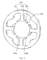
- FIG. 13 illustrates the first stator core lamination according to the fourth embodiment of the present invention.
- FIG. 14 illustrates a second stator core lamination according to the fourth embodiment of the present invention.
- FIG. 15 illustrates a second stator core lamination according to a fifth embodiment of the present invention.
- the single phase permanent magnet motor 10 in accordance with a first embodiment of the present invention includes a stator 20 and a rotor 50 rotatable relative to the stator.
- the stator 20 includes a cylindrical outer housing 21 with one open end, an end cap 23 mounted to the open end of the outer housing 21 , a stator core 30 mounted in the outer housing 21 , an insulating bracket 38 mounted to the stator core 30 , and a winding 39 wound around the stator core and supported by the insulating bracket 38 .
- the stator core 30 is formed by stacking a plurality of first stator core laminations 310 and a plurality of second stator core laminations 320 .
- Each first stator core lamination 310 includes a first outer ring portion 311 , a plurality of first tooth bodies 313 extending inwardly from the first outer ring portion 311 , and a first pole shoe 315 extending from a distal end to two circumferential sides of each first tooth body 313 , with a first slot opening 317 defined between each two adjacent first pole shoes 315 .
- the second stator core lamination 320 includes a second outer ring portion 321 , a plurality of second tooth bodies 323 extending inwardly from the second outer ring portion 321 , and a second pole shoe 325 extending from a distal end to two circumferential sides of each second tooth body 323 , with a second slot opening 327 defined between each two adjacent second pole shoes 325 .
- a width of the second slot opening 327 is greater than a width of the first slot opening 317 .
- the first outer ring portion 311 and the second outer ring portion 321 are stacked along an axial direction of the motor 10
- the first tooth bodies 313 and the corresponding second tooth bodies 323 are stacked along the axial direction of the motor
- the first pole shoes 315 and the corresponding second pole shoes 325 are stacked along the axial direction of the motor.
- the first stator core laminations 310 and the second stator core laminations 320 are alternately stacked in a predetermined pattern.
- the present invention is not intended to limit the number of the first stator core laminations 310 and the second stator core laminations 320 to a particular value, and the pattern in which the first and second stator core laminations 310 and 320 are alternately arranged may also vary depending upon actual requirements.
- each first stator core lamination 310 is alternately arranged with each second stator core lamination 320 or, alternatively, each group of two first stator core laminations 310 is alternately arranged with each group of two or three second stator core laminations 320 .
- each first stator core lamination 310 is alternately arranged with each second stator core lamination 320 . It should be understood that it is not intended to limit the number of the stator core laminations to three layers.
- the winding 39 is wound around the first tooth bodies 313 and second tooth bodies 323 that are stacked along the axial direction of the motor, and is isolated from the stator core 30 by the insulating bracket 38 .
- the rotor 50 is received within a receiving space cooperatively defined by the first pole shoes 315 and the second pole shoes 325 that are stacked along the axial direction of the motor.
- the stacked first pole shoes 315 and second pole shoes 325 , and the rotor 50 bound a radial air gap 41 therebetween.
- the rotor 50 includes a rotary shaft 51 , a rotor core 53 , and a plurality of permanent magnetic poles 55 .
- the rotary shaft 51 passes through a center of the rotor core 53 and is fixed to the rotor core 53 .
- One end of the rotary shaft 51 is mounted to the end cap 23 of the stator 20 through a bearing 24 , and the other end of the rotary shaft 51 is mounted to a bottom of the cylindrical outer housing 21 of the stator 20 through another bearing, such that the rotor 50 is capable of rotation relative to the stator 20 .
- the permanent magnetic poles 55 of the present embodiment are formed by a plurality of permanent magnet members 56 such as four permanent magnet members 56 .
- An outer circumferential surface of the rotor core 53 defines a plurality of axially-extending grooves 54 .
- Each groove 54 is disposed at a junction of two adjacent permanent magnet members 56 to reduce magnetic leakage.
- the permanent magnet members 56 are mounted to the outer circumferential surface of the rotor core 53 .
- inner surfaces of the first pole shoes 315 and second pole shoes 325 are located on concentric circles centered at the center of the rotor 50 in an axial plan view.
- Outer surfaces of all the permanent magnet members 56 are located on a cylindrical surface centered at the center of the rotor 50 , such that an even air gap 41 is defined between the stator pole shoes 315 , 325 and the rotor permanent magnetic poles 55 .
- the width of the first slot opening 317 is greater than zero and less than or equal to four times of a thickness of the air gap 41 .
- the term “thickness” of the air gap 41 used in this disclosure refers to a radial thickness of the air gap.
- the first pole shoe 315 between each two adjacent first tooth bodies 313 defines a positioning slot 318 .
- the number of the positioning slots 318 is the same as the number of the poles of the stator and the number of the permanent magnetic poles 55 , or the number of the positioning slots 318 is an integer times of the number of the permanent magnetic poles 55 .
- the number of the positioning slots 318 is four.
- the stator winding is a concentrated winding and, therefore, the number of the tooth bodies is the same as the number of the poles of the stator.
- the number of the stator tooth bodies can be an integer times of the number of the stator poles, such as, two times, three times or the like.
- Each positioning slot 318 is spaced from the two adjacent first tooth bodies 313 by different distances.
- the positioning slot 318 is closer to one of the two adjacent first tooth bodies 313 , and a center of the positioning slot 318 is offset from a symmetry center of one adjacent first tooth body 313 .
- the positioning slot 318 is mainly used to control the position of the rotor 50 relative to the stator 20 when stopping and prevents the rotor 50 from stopping at a dead point.
- the pole axis of the permanent magnetic pole 55 of the rotor 50 is offset from the center line of the stator tooth body, i.e. a stator pole axis, such that the rotor 50 is offset from a dead point.
- An angle formed between the pole axis of the permanent magnetic pole 55 and the stator pole axis is referred to as a startup angle.
- the startup angle is greater than 45 degrees electric angle and less than 135 degrees electric angle.
- the rotor 50 When the winding 39 of the motor 10 is supplied with an electric current in an opposite direction, the rotor 50 can be started along an opposite direction. It should be understood that, when the startup angle is equal to 90 degrees electric angle, the rotor 50 can be easily started in both directions, i.e. it is the easiest angle to achieve bidirectional startup. When the startup angle is offset from the 90-degree electric angle, the rotor is easier to start in one direction than in the opposite direction. It has been found from a large number of experiments that, when the startup angle is in the range of 45 degrees to 135 degrees electric angle, the startup of the rotor 50 in both directions has good reliability.
- the second stator core lamination 320 is configured to have a symmetrical structure. Portions of each second pole shoe 325 at opposite sides of a center line of the corresponding second tooth body 323 are symmetrical about the center line of the second tooth body 323 .
- the radial thickness of each second pole shoe 325 of the second stator core lamination 320 progressively decreases in a direction from the corresponding second tooth body 323 to the second slot openings 327 , such that the magnetic reluctance of the second pole shoe 325 progressively increases in the direction from the second tooth body 323 to the second slot openings 327 .
- the first stator core lamination 310 and the second stator core lamination 320 may be made from magnetic-conductive soft magnetic material.
- the first stator core lamination 310 and the second stator core lamination 320 are formed by stacking magnetic laminations (silicon laminations commonly used in the industry) along the axial direction of the motor.
- magnetic laminations silicon laminations commonly used in the industry
- centers of the first slot openings 317 align with centers of the second slot openings 327 .
- each of the first slot openings 317 and second slot openings 327 is located at a middle position between two corresponding adjacent first tooth bodies 313 and second tooth bodies 323 .
- the first stator core lamination 310 includes a plurality of first stator core parts 300 joined along a circumferential direction of the stator.
- Each first stator core part 300 includes a first arcuate yoke segment 311 b , a first tooth body 313 extending from the first arcuate yoke segment 311 b, and a first pole shoe 315 extending from a radial distal end of the first tooth body 313 to two circumferential sides of the first tooth body 313 .
- each first stator core part 300 includes a single first tooth body 313 and one associated first pole shoe 315 .
- each stator core part may also include more than one first tooth bodies 313 and corresponding first pole shoes 315 .
- the second stator core lamination 320 also includes a plurality of second stator core parts 300 b joined along the circumferential direction of the stator.
- Each second stator core part 300 b includes a second arcuate yoke segment 321 b, a second tooth body 323 extending from the second arcuate yoke segment 321 b, and a second pole shoe 325 extending from a radial distal end of the second tooth body 323 to two circumferential sides of the second tooth body 323 .
- first stator core parts 300 and the second stator core parts 300 b are stacked together, and the insulating bracket is mounted, followed by the winding of the windings. After the winding of the windings is completed, the stacked first stator core parts 300 and second stator core parts 300 b are joined to obtain the stator core with stator windings.
- a recess-protrusion engagement structure is formed at a joining area between the first arcuate yoke segments 311 b of two adjacent first stator core parts 300 .
- two ends of the first arcuate yoke segment 311 b of each first stator core part 300 for being connected to form the first outer ring portion may be provided with an engagement recess 314 and an engagement protrusion 312 , respectively.
- the engagement recess 314 and the engagement protrusion 312 together form the recess-protrusion engagement structure.
- a recess-protrusion engagement structure 324 may also be formed at a joining area between the second arcuate yoke segments 321 b of two adjacent second stator core parts 300 b.
- the first slot opening between the adjacent first pole shoes 315 and/or the second slot opening between the second pole shoes 325 can have a very small width.
- the width of the first slot opening refers to the distance between two adjacent first pole shoes
- the width of the second slot opening refers to the distance between two adjacent second pole shoes.
- the rotor 60 includes a rotor core 63 and ring shaped permanent magnetic poles 65 arranged along the circumferential direction of the rotor core 63 .
- An outer circumferential surface of the ring shaped permanent magnetic poles 65 is concentric with the inner circumferential surfaces of the first pole shoes and second pole shoes, such that the air gap 41 formed therebetween is an even air gap.
- the inner surfaces of the first pole shoes and the second pole shoes are located on a circle centered at the center of the rotor 60 in the axial plan view.
- An outer surface of the ring shaped permanent magnetic poles 65 is cylindrical, and is located on a circle centered at the center of the rotor 60 in the axial plan view, thus forming the even air gap between the inner circumferential surface of the first pole shoes and second pole shoes and the outer circumferential surface of the permanent magnetic poles 65 .
- the ring shaped permanent magnet poles 65 may be formed by a single ring shaped permanent magnet member 66 mounted to the outer circumferential surface of the rotor core 63 .
- An outer circumferential surface of the rotor core 63 is provided with a plurality of axially extending grooves 64 . Each groove 64 is located at a junction between two permanent magnetic poles 65 to reduce magnetic leakage.
- the rotor 70 includes a plurality of permanent magnetic poles 75 arranged along a circumferential direction of the rotor.
- An outer surface of each permanent magnetic pole 75 is an arc surface.
- the outer circumferential surface of the permanent magnetic pole 75 is spaced from a center of the rotor 70 by a distance that progressively decreases from a circumferential center to two circumferential ends of the outer circumferential surface.
- the stator may be the same as the stator of the embodiments above.
- the permanent magnetic poles 75 and the inner circumferential surfaces of the first pole shoes 315 and second pole shoes 325 form therebetween a symmetrical uneven air gap.
- the symmetrical uneven air gap has a maximum thickness that is at least 1.5 times of its minimum thickness.
- the width of the first slot opening 317 is greater than zero and less than or equal to four times of the minimum thickness of the uneven air gap.
- Each permanent magnetic pole 75 may be formed by a single permanent magnet member 76 .
- the rotor 70 further includes a rotor core 73 .
- the permanent magnet member 76 is mounted to an outer circumferential surface of the rotor core 73 .
- the outer circumferential surface of the rotor core 73 is provided with a plurality of axially extending grooves 74 .
- Each groove 74 is located at a junction between two adjacent permanent magnetic poles 75 to reduce magnetic leakage.
- the stator core in order to increase the winding efficiency of the windings 39 , may be of a split-type structure.
- the first tooth bodies 313 and the first outer ring portion 311 of FIG. 4 of the first embodiment are separately formed and then assembled together.
- the second tooth bodies 323 and the second outer ring portion 321 are separately formed and then assembled together.
- the second tooth bodies 323 and the corresponding second pole shoes 325 are integrally formed into an integral structure, and this integral structure is separate from the second outer ring portion 321 .
- the first tooth bodies 313 and the second tooth bodies 323 are stacked with each other. The insulating bracket is then mounted and the windings are wound.
- the first outer ring portions 311 and the second outer ring portions 321 are stacked to form a cylinder. After winding of the windings is completed, the first tooth bodies 313 and the second tooth bodies 323 are mounted inside the cylinder formed by stacked first outer ring portions 311 and second outer ring portions 321 , thus achieving the stator core with windings.
- the rotor 80 includes a plurality of permanent magnetic poles 85 arranged along a circumferential direction of the rotor 80 .
- An outer surface of each permanent magnetic pole 85 is an arc surface.
- Each permanent magnetic pole 85 is formed by a single permanent magnet member mounted to an outer circumferential surface of a rotor core 83 .
- the outer circumferential surface of each permanent magnetic pole 85 is spaced from a center of the rotor 80 by a distance that progressively decreases from a circumferential center to two circumferential ends of the outer circumferential surface.
- the outer circumferential surface of the rotor core 83 is provided with a plurality of axially extending grooves 84 .
- Each groove 84 is located at a junction between two adjacent permanent magnetic poles 85 to reduce magnetic leakage.
- the thickness of the permanent magnet member is uniform, while the outer circumferential surface of the rotor core 83 between each two grooves 84 is spaced from the center of the rotor 80 by a distance that progressively decreases from a circumferential center to two circumferential ends, and the inner circumferential surfaces of the permanent magnet members match with the outer circumferential surfaces of the rotor core 83 in shape.
- the outer circumferential surface of the rotor core 83 is located on a cylindrical surface centered at the center of the rotor 80 , while the thickness of the permanent magnet member is non-uniform, which progressively decreases from a circumferential center to two circumferential ends thereof.
- the first stator core lamination 310 of this embodiment does not form a positioning slot.
- the inner surface of the first pole shoe 315 is located on a cylindrical surface.
- portions of each second pole shoe 325 of the second stator core lamination 320 at opposite sides of a center line of the corresponding second tooth body 323 are asymmetric about the center line of the second tooth body 323 .
- a radial width of the portion 325 a of each second pole shoe 325 on the left side of the tooth body 323 is greater than a radial width of the portion 325 b of the pole shoe 325 on the right side of the tooth body 323 , the inner surface of each second pole shoe 325 is spaced from the rotor center by a changing distance.
- each second pole shoe 325 is spaced from the rotor center by a distance that progressively increases from one end to the other end along the circumferential direction of the motor, such that the air gap 41 formed between the stator 20 and the rotor 80 progressively increases from one end to the other end of each second pole shoe 325 , thereby achieving the positioning of the rotor 80 .
- portions of each second pole shoe 325 of the second stator core lamination 320 at opposite sides of a center line of the corresponding second tooth body 323 have different lengths.
- the inner surfaces of the second pole shoes 325 may also be located on a cylindrical surface centered at the center of the rotor. That is, the inner surfaces of the second pole shoes 325 are spaced from the rotor center by a uniform distance, which likewise makes the initial position of the rotor offset from the dead point.
- the second slot opening 327 of the second stator core lamination 320 may also be a small slot opening, a width of the second slot opening 327 is less than or equal to a width of a first slot opening 317 of a first stator core lamination 310 .
- the single phase permanent magnet motor of embodiments of the present invention includes a stator core that is formed by stacking first stator core laminations and second stator core laminations with different inner structures. This reduces the vibration and noise produced in the conventional motor due to the unduly large slot openings, thereby improving the reliability of the motor startup.
- the startup angle and the cogging torque needed during startup can be easily adjusted according to design requirements, thus reducing or eliminating the startup dead points and hence increasing the reliability of the motor startup.
- the motor startup angle can be easily adjusted by adjusting the position of the positioning slots of the first pole shoes.
- the startup angle Q is greater than a 45-degree electric angle and less than a 135-degree electric angle, the rotor can achieve bidirectional startup.
- the width of the first slot opening of the first stator core lamination is less than or equal to four times of the thickness of the air gap, which avoids a sudden change of magnetic reluctance that would occur in the prior art due to the large slot opening between the adjacent stator pole shoes, thereby reducing the cogging torque of the motor.
- the stator core is of a split-type structure, the winding process can be performed by using a high efficiency winding machine prior to the assembly of the tooth bodies and the outer ring portion, which increases the winding efficiency.
- the rotors and stators of the above embodiments may be used in different combinations, i.e. the rotor of each embodiment may be used in combination with the stator of any embodiment, and the stator of each embodiment may be used in combination with the rotor of any embodiment.
Abstract
Description
Claims (18)
Applications Claiming Priority (3)
| Application Number | Priority Date | Filing Date | Title |
|---|---|---|---|
| CN201510575665.X | 2015-09-10 | ||
| CN201510575665.XA CN106533000A (en) | 2015-09-10 | 2015-09-10 | Single-phase permanent magnet motor |
| CN201510575665 | 2015-09-10 |
Publications (2)
| Publication Number | Publication Date |
|---|---|
| US20170077769A1 US20170077769A1 (en) | 2017-03-16 |
| US10491058B2 true US10491058B2 (en) | 2019-11-26 |
Family
ID=57629758
Family Applications (1)
| Application Number | Title | Priority Date | Filing Date |
|---|---|---|---|
| US15/260,734 Expired - Fee Related US10491058B2 (en) | 2015-09-10 | 2016-09-09 | Single phase permanent magnet motor |
Country Status (7)
| Country | Link |
|---|---|
| US (1) | US10491058B2 (en) |
| JP (1) | JP2017060394A (en) |
| KR (1) | KR20170035794A (en) |
| CN (1) | CN106533000A (en) |
| BR (1) | BR102016020629A2 (en) |
| DE (2) | DE202016104830U1 (en) |
| MX (1) | MX2016011714A (en) |
Families Citing this family (7)
| Publication number | Priority date | Publication date | Assignee | Title |
|---|---|---|---|---|
| US10998777B2 (en) * | 2017-02-24 | 2021-05-04 | Mitsubishi Electric Corporation | Electric motor |
| CN109586426A (en) * | 2017-09-29 | 2019-04-05 | 广东朗科智能电气有限公司 | Motor of dust collector and its motor stator |
| CN108667220A (en) * | 2018-07-25 | 2018-10-16 | 安徽皖南电机股份有限公司 | Half assembly of low speed large torque moment permanent-magnet direct driving motor |
| WO2020106864A1 (en) * | 2018-11-20 | 2020-05-28 | Crs Holdings, Inc. | A method of making a multi-material segmented stator for a rotating electric machine and a stator made by said method |
| CN109861479A (en) * | 2019-04-10 | 2019-06-07 | 珠海凯邦电机制造有限公司 | For improving the stator punching, stator and motor of resonance noise |
| DE102020108516A1 (en) | 2020-03-27 | 2021-09-30 | Feaam Gmbh | Stator, rotor and electrical machine |
| CN111769697B (en) * | 2020-07-08 | 2022-04-05 | 东南大学盐城新能源汽车研究院 | Method for weakening torque ripple and induction voltage of electric excitation magnetic flux switching motor |
Citations (11)
| Publication number | Priority date | Publication date | Assignee | Title |
|---|---|---|---|---|
| US3469136A (en) * | 1968-03-21 | 1969-09-23 | Lucas Industries Ltd | Laminated stators for dynamo electric machines |
| US4496887A (en) * | 1982-03-10 | 1985-01-29 | Japan Servo Co., Ltd. | Direct-current brushless motor |
| US5250867A (en) * | 1991-11-20 | 1993-10-05 | General Electric Company | Permanent magnet brushless DC motor having reduced cogging |
| US5773908A (en) | 1993-02-22 | 1998-06-30 | General Electric Company | Single phase motor with positive torque parking positions |
| US5861699A (en) * | 1996-03-12 | 1999-01-19 | Sole S.P.A. | Electric machine, in particular electric motor |
| USRE37576E1 (en) * | 1993-02-22 | 2002-03-12 | General Electric Company | Single phase motor with positive torque parking positions |
| US6747379B2 (en) * | 2002-03-11 | 2004-06-08 | Labrush Edward Clarence | Dynamoelectric machine with reduced vibration |
| US20080197794A1 (en) * | 2007-01-02 | 2008-08-21 | Ami Semiconductor Belgium Bvba | Method and apparatus for driving a dc motor |
| JP2009189163A (en) | 2008-02-06 | 2009-08-20 | Nippon Densan Corp | Electric motor |
| US20120256513A1 (en) * | 2009-12-02 | 2012-10-11 | Brose Fahrzeugteile Gmbh & Co Kg, Wurzburg | Stator for an electric motor and method for the production thereof |
| US20130002058A1 (en) * | 2011-06-30 | 2013-01-03 | Mcintosh Devon R | Low-Cost Low-Cog PM Machine |
Family Cites Families (2)
| Publication number | Priority date | Publication date | Assignee | Title |
|---|---|---|---|---|
| JPH1118327A (en) * | 1997-06-25 | 1999-01-22 | Iwaki:Kk | Synchronous motor |
| JP2002095194A (en) * | 2000-09-11 | 2002-03-29 | Daihatsu Motor Co Ltd | Embedded-magnet motor |
-
2015
- 2015-09-10 CN CN201510575665.XA patent/CN106533000A/en active Pending
-
2016
- 2016-09-01 DE DE202016104830.3U patent/DE202016104830U1/en not_active Expired - Lifetime
- 2016-09-01 DE DE102016116386.4A patent/DE102016116386A1/en not_active Withdrawn
- 2016-09-06 BR BR102016020629A patent/BR102016020629A2/en not_active Application Discontinuation
- 2016-09-09 MX MX2016011714A patent/MX2016011714A/en unknown
- 2016-09-09 US US15/260,734 patent/US10491058B2/en not_active Expired - Fee Related
- 2016-09-09 KR KR1020160116345A patent/KR20170035794A/en unknown
- 2016-09-12 JP JP2016177352A patent/JP2017060394A/en not_active Abandoned
Patent Citations (11)
| Publication number | Priority date | Publication date | Assignee | Title |
|---|---|---|---|---|
| US3469136A (en) * | 1968-03-21 | 1969-09-23 | Lucas Industries Ltd | Laminated stators for dynamo electric machines |
| US4496887A (en) * | 1982-03-10 | 1985-01-29 | Japan Servo Co., Ltd. | Direct-current brushless motor |
| US5250867A (en) * | 1991-11-20 | 1993-10-05 | General Electric Company | Permanent magnet brushless DC motor having reduced cogging |
| US5773908A (en) | 1993-02-22 | 1998-06-30 | General Electric Company | Single phase motor with positive torque parking positions |
| USRE37576E1 (en) * | 1993-02-22 | 2002-03-12 | General Electric Company | Single phase motor with positive torque parking positions |
| US5861699A (en) * | 1996-03-12 | 1999-01-19 | Sole S.P.A. | Electric machine, in particular electric motor |
| US6747379B2 (en) * | 2002-03-11 | 2004-06-08 | Labrush Edward Clarence | Dynamoelectric machine with reduced vibration |
| US20080197794A1 (en) * | 2007-01-02 | 2008-08-21 | Ami Semiconductor Belgium Bvba | Method and apparatus for driving a dc motor |
| JP2009189163A (en) | 2008-02-06 | 2009-08-20 | Nippon Densan Corp | Electric motor |
| US20120256513A1 (en) * | 2009-12-02 | 2012-10-11 | Brose Fahrzeugteile Gmbh & Co Kg, Wurzburg | Stator for an electric motor and method for the production thereof |
| US20130002058A1 (en) * | 2011-06-30 | 2013-01-03 | Mcintosh Devon R | Low-Cost Low-Cog PM Machine |
Also Published As
| Publication number | Publication date |
|---|---|
| BR102016020629A2 (en) | 2017-03-14 |
| US20170077769A1 (en) | 2017-03-16 |
| DE102016116386A1 (en) | 2017-03-16 |
| KR20170035794A (en) | 2017-03-31 |
| JP2017060394A (en) | 2017-03-23 |
| MX2016011714A (en) | 2017-08-10 |
| CN106533000A (en) | 2017-03-22 |
| DE202016104830U1 (en) | 2016-12-08 |
Similar Documents
| Publication | Publication Date | Title |
|---|---|---|
| US10491058B2 (en) | Single phase permanent magnet motor | |
| US10110076B2 (en) | Single-phase brushless motor | |
| US11489375B2 (en) | Single phase permanent magnet motor | |
| US20170077791A1 (en) | Single Phase Permanent Magnet Motor | |
| US10299559B2 (en) | Single phase permanent magnet motor and hair dryer using the same | |
| US10862353B2 (en) | Axial gap motor rotor and axial gap motor | |
| US20170063208A1 (en) | Single Phase Permanent Magnet Motor And Method For Making Same | |
| KR20170039606A (en) | Brushless motor | |
| US10630155B2 (en) | Single phase permanent magnet motor | |
| US10461590B2 (en) | Single phase permanent magnet motor | |
| KR20170039605A (en) | Brushless motor | |
| KR20170039603A (en) | Brushless Motor | |
| KR20170039604A (en) | Brushless Motor | |
| US10404109B2 (en) | Single phase permanent magnet motor and stator core | |
| US10236758B2 (en) | Single phase permanent magnet motor and stator core thereof | |
| JP2017103957A (en) | Stator, motor and method of manufacturing the stator |
Legal Events
| Date | Code | Title | Description |
|---|---|---|---|
| AS | Assignment |
Owner name: JOHNSON ELECTRIC S.A., SWITZERLAND Free format text: ASSIGNMENT OF ASSIGNORS INTEREST;ASSIGNORS:LI, YUE;ZHOU, CHUI YOU;WANG, YONG;AND OTHERS;REEL/FRAME:039701/0424 Effective date: 20160825 |
|
| STPP | Information on status: patent application and granting procedure in general |
Free format text: RESPONSE TO NON-FINAL OFFICE ACTION ENTERED AND FORWARDED TO EXAMINER |
|
| AS | Assignment |
Owner name: JOHNSON ELECTRIC INTERNATIONAL AG, SWITZERLAND Free format text: MERGER;ASSIGNOR:JOHNSON ELECTRIC S.A.;REEL/FRAME:048748/0015 Effective date: 20180925 |
|
| STPP | Information on status: patent application and granting procedure in general |
Free format text: NON FINAL ACTION MAILED |
|
| STPP | Information on status: patent application and granting procedure in general |
Free format text: NOTICE OF ALLOWANCE MAILED -- APPLICATION RECEIVED IN OFFICE OF PUBLICATIONS |
|
| STPP | Information on status: patent application and granting procedure in general |
Free format text: PUBLICATIONS -- ISSUE FEE PAYMENT VERIFIED |
|
| STCF | Information on status: patent grant |
Free format text: PATENTED CASE |
|
| FEPP | Fee payment procedure |
Free format text: MAINTENANCE FEE REMINDER MAILED (ORIGINAL EVENT CODE: REM.); ENTITY STATUS OF PATENT OWNER: LARGE ENTITY |
|
| LAPS | Lapse for failure to pay maintenance fees |
Free format text: PATENT EXPIRED FOR FAILURE TO PAY MAINTENANCE FEES (ORIGINAL EVENT CODE: EXP.); ENTITY STATUS OF PATENT OWNER: LARGE ENTITY |
|
| STCH | Information on status: patent discontinuation |
Free format text: PATENT EXPIRED DUE TO NONPAYMENT OF MAINTENANCE FEES UNDER 37 CFR 1.362 |
|
| FP | Lapsed due to failure to pay maintenance fee |
Effective date: 20231126 |