US10483515B2 - Power storage device, power storage system, electronic device, electric vehicle, and power system - Google Patents
Power storage device, power storage system, electronic device, electric vehicle, and power system Download PDFInfo
- Publication number
- US10483515B2 US10483515B2 US15/111,215 US201515111215A US10483515B2 US 10483515 B2 US10483515 B2 US 10483515B2 US 201515111215 A US201515111215 A US 201515111215A US 10483515 B2 US10483515 B2 US 10483515B2
- Authority
- US
- United States
- Prior art keywords
- battery
- connection terminal
- power storage
- battery cells
- unit
- Prior art date
- Legal status (The legal status is an assumption and is not a legal conclusion. Google has not performed a legal analysis and makes no representation as to the accuracy of the status listed.)
- Active
Links
Images


Classifications
-
- H01M2/206—
-
- B—PERFORMING OPERATIONS; TRANSPORTING
- B60—VEHICLES IN GENERAL
- B60L—PROPULSION OF ELECTRICALLY-PROPELLED VEHICLES; SUPPLYING ELECTRIC POWER FOR AUXILIARY EQUIPMENT OF ELECTRICALLY-PROPELLED VEHICLES; ELECTRODYNAMIC BRAKE SYSTEMS FOR VEHICLES IN GENERAL; MAGNETIC SUSPENSION OR LEVITATION FOR VEHICLES; MONITORING OPERATING VARIABLES OF ELECTRICALLY-PROPELLED VEHICLES; ELECTRIC SAFETY DEVICES FOR ELECTRICALLY-PROPELLED VEHICLES
- B60L3/00—Electric devices on electrically-propelled vehicles for safety purposes; Monitoring operating variables, e.g. speed, deceleration or energy consumption
- B60L3/0023—Detecting, eliminating, remedying or compensating for drive train abnormalities, e.g. failures within the drive train
- B60L3/0046—Detecting, eliminating, remedying or compensating for drive train abnormalities, e.g. failures within the drive train relating to electric energy storage systems, e.g. batteries or capacitors
-
- B—PERFORMING OPERATIONS; TRANSPORTING
- B60—VEHICLES IN GENERAL
- B60L—PROPULSION OF ELECTRICALLY-PROPELLED VEHICLES; SUPPLYING ELECTRIC POWER FOR AUXILIARY EQUIPMENT OF ELECTRICALLY-PROPELLED VEHICLES; ELECTRODYNAMIC BRAKE SYSTEMS FOR VEHICLES IN GENERAL; MAGNETIC SUSPENSION OR LEVITATION FOR VEHICLES; MONITORING OPERATING VARIABLES OF ELECTRICALLY-PROPELLED VEHICLES; ELECTRIC SAFETY DEVICES FOR ELECTRICALLY-PROPELLED VEHICLES
- B60L50/00—Electric propulsion with power supplied within the vehicle
- B60L50/50—Electric propulsion with power supplied within the vehicle using propulsion power supplied by batteries or fuel cells
- B60L50/60—Electric propulsion with power supplied within the vehicle using propulsion power supplied by batteries or fuel cells using power supplied by batteries
- B60L50/64—Constructional details of batteries specially adapted for electric vehicles
-
- B—PERFORMING OPERATIONS; TRANSPORTING
- B60—VEHICLES IN GENERAL
- B60L—PROPULSION OF ELECTRICALLY-PROPELLED VEHICLES; SUPPLYING ELECTRIC POWER FOR AUXILIARY EQUIPMENT OF ELECTRICALLY-PROPELLED VEHICLES; ELECTRODYNAMIC BRAKE SYSTEMS FOR VEHICLES IN GENERAL; MAGNETIC SUSPENSION OR LEVITATION FOR VEHICLES; MONITORING OPERATING VARIABLES OF ELECTRICALLY-PROPELLED VEHICLES; ELECTRIC SAFETY DEVICES FOR ELECTRICALLY-PROPELLED VEHICLES
- B60L50/00—Electric propulsion with power supplied within the vehicle
- B60L50/50—Electric propulsion with power supplied within the vehicle using propulsion power supplied by batteries or fuel cells
- B60L50/60—Electric propulsion with power supplied within the vehicle using propulsion power supplied by batteries or fuel cells using power supplied by batteries
- B60L50/66—Arrangements of batteries
-
- B—PERFORMING OPERATIONS; TRANSPORTING
- B60—VEHICLES IN GENERAL
- B60L—PROPULSION OF ELECTRICALLY-PROPELLED VEHICLES; SUPPLYING ELECTRIC POWER FOR AUXILIARY EQUIPMENT OF ELECTRICALLY-PROPELLED VEHICLES; ELECTRODYNAMIC BRAKE SYSTEMS FOR VEHICLES IN GENERAL; MAGNETIC SUSPENSION OR LEVITATION FOR VEHICLES; MONITORING OPERATING VARIABLES OF ELECTRICALLY-PROPELLED VEHICLES; ELECTRIC SAFETY DEVICES FOR ELECTRICALLY-PROPELLED VEHICLES
- B60L53/00—Methods of charging batteries, specially adapted for electric vehicles; Charging stations or on-board charging equipment therefor; Exchange of energy storage elements in electric vehicles
- B60L53/50—Charging stations characterised by energy-storage or power-generation means
- B60L53/56—Mechanical storage means, e.g. fly wheels
-
- B—PERFORMING OPERATIONS; TRANSPORTING
- B60—VEHICLES IN GENERAL
- B60L—PROPULSION OF ELECTRICALLY-PROPELLED VEHICLES; SUPPLYING ELECTRIC POWER FOR AUXILIARY EQUIPMENT OF ELECTRICALLY-PROPELLED VEHICLES; ELECTRODYNAMIC BRAKE SYSTEMS FOR VEHICLES IN GENERAL; MAGNETIC SUSPENSION OR LEVITATION FOR VEHICLES; MONITORING OPERATING VARIABLES OF ELECTRICALLY-PROPELLED VEHICLES; ELECTRIC SAFETY DEVICES FOR ELECTRICALLY-PROPELLED VEHICLES
- B60L58/00—Methods or circuit arrangements for monitoring or controlling batteries or fuel cells, specially adapted for electric vehicles
- B60L58/10—Methods or circuit arrangements for monitoring or controlling batteries or fuel cells, specially adapted for electric vehicles for monitoring or controlling batteries
- B60L58/12—Methods or circuit arrangements for monitoring or controlling batteries or fuel cells, specially adapted for electric vehicles for monitoring or controlling batteries responding to state of charge [SoC]
- B60L58/14—Preventing excessive discharging
-
- B—PERFORMING OPERATIONS; TRANSPORTING
- B60—VEHICLES IN GENERAL
- B60L—PROPULSION OF ELECTRICALLY-PROPELLED VEHICLES; SUPPLYING ELECTRIC POWER FOR AUXILIARY EQUIPMENT OF ELECTRICALLY-PROPELLED VEHICLES; ELECTRODYNAMIC BRAKE SYSTEMS FOR VEHICLES IN GENERAL; MAGNETIC SUSPENSION OR LEVITATION FOR VEHICLES; MONITORING OPERATING VARIABLES OF ELECTRICALLY-PROPELLED VEHICLES; ELECTRIC SAFETY DEVICES FOR ELECTRICALLY-PROPELLED VEHICLES
- B60L58/00—Methods or circuit arrangements for monitoring or controlling batteries or fuel cells, specially adapted for electric vehicles
- B60L58/10—Methods or circuit arrangements for monitoring or controlling batteries or fuel cells, specially adapted for electric vehicles for monitoring or controlling batteries
- B60L58/24—Methods or circuit arrangements for monitoring or controlling batteries or fuel cells, specially adapted for electric vehicles for monitoring or controlling batteries for controlling the temperature of batteries
- B60L58/26—Methods or circuit arrangements for monitoring or controlling batteries or fuel cells, specially adapted for electric vehicles for monitoring or controlling batteries for controlling the temperature of batteries by cooling
-
- B—PERFORMING OPERATIONS; TRANSPORTING
- B60—VEHICLES IN GENERAL
- B60L—PROPULSION OF ELECTRICALLY-PROPELLED VEHICLES; SUPPLYING ELECTRIC POWER FOR AUXILIARY EQUIPMENT OF ELECTRICALLY-PROPELLED VEHICLES; ELECTRODYNAMIC BRAKE SYSTEMS FOR VEHICLES IN GENERAL; MAGNETIC SUSPENSION OR LEVITATION FOR VEHICLES; MONITORING OPERATING VARIABLES OF ELECTRICALLY-PROPELLED VEHICLES; ELECTRIC SAFETY DEVICES FOR ELECTRICALLY-PROPELLED VEHICLES
- B60L58/00—Methods or circuit arrangements for monitoring or controlling batteries or fuel cells, specially adapted for electric vehicles
- B60L58/10—Methods or circuit arrangements for monitoring or controlling batteries or fuel cells, specially adapted for electric vehicles for monitoring or controlling batteries
- B60L58/24—Methods or circuit arrangements for monitoring or controlling batteries or fuel cells, specially adapted for electric vehicles for monitoring or controlling batteries for controlling the temperature of batteries
- B60L58/27—Methods or circuit arrangements for monitoring or controlling batteries or fuel cells, specially adapted for electric vehicles for monitoring or controlling batteries for controlling the temperature of batteries by heating
-
- H—ELECTRICITY
- H01—ELECTRIC ELEMENTS
- H01M—PROCESSES OR MEANS, e.g. BATTERIES, FOR THE DIRECT CONVERSION OF CHEMICAL ENERGY INTO ELECTRICAL ENERGY
- H01M10/00—Secondary cells; Manufacture thereof
- H01M10/05—Accumulators with non-aqueous electrolyte
- H01M10/052—Li-accumulators
- H01M10/0525—Rocking-chair batteries, i.e. batteries with lithium insertion or intercalation in both electrodes; Lithium-ion batteries
-
- H—ELECTRICITY
- H01—ELECTRIC ELEMENTS
- H01M—PROCESSES OR MEANS, e.g. BATTERIES, FOR THE DIRECT CONVERSION OF CHEMICAL ENERGY INTO ELECTRICAL ENERGY
- H01M10/00—Secondary cells; Manufacture thereof
- H01M10/42—Methods or arrangements for servicing or maintenance of secondary cells or secondary half-cells
- H01M10/425—Structural combination with electronic components, e.g. electronic circuits integrated to the outside of the casing
- H01M10/4257—Smart batteries, e.g. electronic circuits inside the housing of the cells or batteries
-
- H—ELECTRICITY
- H01—ELECTRIC ELEMENTS
- H01M—PROCESSES OR MEANS, e.g. BATTERIES, FOR THE DIRECT CONVERSION OF CHEMICAL ENERGY INTO ELECTRICAL ENERGY
- H01M10/00—Secondary cells; Manufacture thereof
- H01M10/42—Methods or arrangements for servicing or maintenance of secondary cells or secondary half-cells
- H01M10/46—Accumulators structurally combined with charging apparatus
-
- H—ELECTRICITY
- H01—ELECTRIC ELEMENTS
- H01M—PROCESSES OR MEANS, e.g. BATTERIES, FOR THE DIRECT CONVERSION OF CHEMICAL ENERGY INTO ELECTRICAL ENERGY
- H01M10/00—Secondary cells; Manufacture thereof
- H01M10/42—Methods or arrangements for servicing or maintenance of secondary cells or secondary half-cells
- H01M10/48—Accumulators combined with arrangements for measuring, testing or indicating the condition of cells, e.g. the level or density of the electrolyte
- H01M10/482—Accumulators combined with arrangements for measuring, testing or indicating the condition of cells, e.g. the level or density of the electrolyte for several batteries or cells simultaneously or sequentially
-
- H—ELECTRICITY
- H01—ELECTRIC ELEMENTS
- H01M—PROCESSES OR MEANS, e.g. BATTERIES, FOR THE DIRECT CONVERSION OF CHEMICAL ENERGY INTO ELECTRICAL ENERGY
- H01M10/00—Secondary cells; Manufacture thereof
- H01M10/42—Methods or arrangements for servicing or maintenance of secondary cells or secondary half-cells
- H01M10/48—Accumulators combined with arrangements for measuring, testing or indicating the condition of cells, e.g. the level or density of the electrolyte
- H01M10/486—Accumulators combined with arrangements for measuring, testing or indicating the condition of cells, e.g. the level or density of the electrolyte for measuring temperature
-
- H—ELECTRICITY
- H01—ELECTRIC ELEMENTS
- H01M—PROCESSES OR MEANS, e.g. BATTERIES, FOR THE DIRECT CONVERSION OF CHEMICAL ENERGY INTO ELECTRICAL ENERGY
- H01M10/00—Secondary cells; Manufacture thereof
- H01M10/60—Heating or cooling; Temperature control
- H01M10/65—Means for temperature control structurally associated with the cells
- H01M10/655—Solid structures for heat exchange or heat conduction
- H01M10/6553—Terminals or leads
-
- H01M2/1077—
-
- H01M2/348—
-
- H—ELECTRICITY
- H01—ELECTRIC ELEMENTS
- H01M—PROCESSES OR MEANS, e.g. BATTERIES, FOR THE DIRECT CONVERSION OF CHEMICAL ENERGY INTO ELECTRICAL ENERGY
- H01M50/00—Constructional details or processes of manufacture of the non-active parts of electrochemical cells other than fuel cells, e.g. hybrid cells
- H01M50/20—Mountings; Secondary casings or frames; Racks, modules or packs; Suspension devices; Shock absorbers; Transport or carrying devices; Holders
- H01M50/204—Racks, modules or packs for multiple batteries or multiple cells
- H01M50/207—Racks, modules or packs for multiple batteries or multiple cells characterised by their shape
- H01M50/213—Racks, modules or packs for multiple batteries or multiple cells characterised by their shape adapted for cells having curved cross-section, e.g. round or elliptic
-
- H—ELECTRICITY
- H01—ELECTRIC ELEMENTS
- H01M—PROCESSES OR MEANS, e.g. BATTERIES, FOR THE DIRECT CONVERSION OF CHEMICAL ENERGY INTO ELECTRICAL ENERGY
- H01M50/00—Constructional details or processes of manufacture of the non-active parts of electrochemical cells other than fuel cells, e.g. hybrid cells
- H01M50/20—Mountings; Secondary casings or frames; Racks, modules or packs; Suspension devices; Shock absorbers; Transport or carrying devices; Holders
- H01M50/296—Mountings; Secondary casings or frames; Racks, modules or packs; Suspension devices; Shock absorbers; Transport or carrying devices; Holders characterised by terminals of battery packs
-
- H—ELECTRICITY
- H01—ELECTRIC ELEMENTS
- H01M—PROCESSES OR MEANS, e.g. BATTERIES, FOR THE DIRECT CONVERSION OF CHEMICAL ENERGY INTO ELECTRICAL ENERGY
- H01M50/00—Constructional details or processes of manufacture of the non-active parts of electrochemical cells other than fuel cells, e.g. hybrid cells
- H01M50/50—Current conducting connections for cells or batteries
- H01M50/502—Interconnectors for connecting terminals of adjacent batteries; Interconnectors for connecting cells outside a battery casing
- H01M50/509—Interconnectors for connecting terminals of adjacent batteries; Interconnectors for connecting cells outside a battery casing characterised by the type of connection, e.g. mixed connections
- H01M50/512—Connection only in parallel
-
- H—ELECTRICITY
- H01—ELECTRIC ELEMENTS
- H01M—PROCESSES OR MEANS, e.g. BATTERIES, FOR THE DIRECT CONVERSION OF CHEMICAL ENERGY INTO ELECTRICAL ENERGY
- H01M50/00—Constructional details or processes of manufacture of the non-active parts of electrochemical cells other than fuel cells, e.g. hybrid cells
- H01M50/50—Current conducting connections for cells or batteries
- H01M50/572—Means for preventing undesired use or discharge
- H01M50/574—Devices or arrangements for the interruption of current
- H01M50/581—Devices or arrangements for the interruption of current in response to temperature
-
- H—ELECTRICITY
- H02—GENERATION; CONVERSION OR DISTRIBUTION OF ELECTRIC POWER
- H02J—CIRCUIT ARRANGEMENTS OR SYSTEMS FOR SUPPLYING OR DISTRIBUTING ELECTRIC POWER; SYSTEMS FOR STORING ELECTRIC ENERGY
- H02J7/00—Circuit arrangements for charging or depolarising batteries or for supplying loads from batteries
- H02J7/0013—Circuit arrangements for charging or depolarising batteries or for supplying loads from batteries acting upon several batteries simultaneously or sequentially
- H02J7/0024—Parallel/serial switching of connection of batteries to charge or load circuit
-
- H—ELECTRICITY
- H02—GENERATION; CONVERSION OR DISTRIBUTION OF ELECTRIC POWER
- H02J—CIRCUIT ARRANGEMENTS OR SYSTEMS FOR SUPPLYING OR DISTRIBUTING ELECTRIC POWER; SYSTEMS FOR STORING ELECTRIC ENERGY
- H02J7/00—Circuit arrangements for charging or depolarising batteries or for supplying loads from batteries
- H02J7/007—Regulation of charging or discharging current or voltage
- H02J7/007188—Regulation of charging or discharging current or voltage the charge cycle being controlled or terminated in response to non-electric parameters
- H02J7/007192—Regulation of charging or discharging current or voltage the charge cycle being controlled or terminated in response to non-electric parameters in response to temperature
- H02J7/007194—Regulation of charging or discharging current or voltage the charge cycle being controlled or terminated in response to non-electric parameters in response to temperature of the battery
-
- H—ELECTRICITY
- H02—GENERATION; CONVERSION OR DISTRIBUTION OF ELECTRIC POWER
- H02J—CIRCUIT ARRANGEMENTS OR SYSTEMS FOR SUPPLYING OR DISTRIBUTING ELECTRIC POWER; SYSTEMS FOR STORING ELECTRIC ENERGY
- H02J7/00—Circuit arrangements for charging or depolarising batteries or for supplying loads from batteries
- H02J7/02—Circuit arrangements for charging or depolarising batteries or for supplying loads from batteries for charging batteries from ac mains by converters
- H02J7/04—Regulation of charging current or voltage
-
- H02J7/047—
-
- B—PERFORMING OPERATIONS; TRANSPORTING
- B60—VEHICLES IN GENERAL
- B60L—PROPULSION OF ELECTRICALLY-PROPELLED VEHICLES; SUPPLYING ELECTRIC POWER FOR AUXILIARY EQUIPMENT OF ELECTRICALLY-PROPELLED VEHICLES; ELECTRODYNAMIC BRAKE SYSTEMS FOR VEHICLES IN GENERAL; MAGNETIC SUSPENSION OR LEVITATION FOR VEHICLES; MONITORING OPERATING VARIABLES OF ELECTRICALLY-PROPELLED VEHICLES; ELECTRIC SAFETY DEVICES FOR ELECTRICALLY-PROPELLED VEHICLES
- B60L2240/00—Control parameters of input or output; Target parameters
- B60L2240/40—Drive Train control parameters
- B60L2240/54—Drive Train control parameters related to batteries
- B60L2240/545—Temperature
-
- H—ELECTRICITY
- H01—ELECTRIC ELEMENTS
- H01M—PROCESSES OR MEANS, e.g. BATTERIES, FOR THE DIRECT CONVERSION OF CHEMICAL ENERGY INTO ELECTRICAL ENERGY
- H01M10/00—Secondary cells; Manufacture thereof
- H01M10/04—Construction or manufacture in general
- H01M10/0422—Cells or battery with cylindrical casing
-
- H—ELECTRICITY
- H01—ELECTRIC ELEMENTS
- H01M—PROCESSES OR MEANS, e.g. BATTERIES, FOR THE DIRECT CONVERSION OF CHEMICAL ENERGY INTO ELECTRICAL ENERGY
- H01M10/00—Secondary cells; Manufacture thereof
- H01M10/60—Heating or cooling; Temperature control
- H01M10/62—Heating or cooling; Temperature control specially adapted for specific applications
- H01M10/625—Vehicles
-
- H—ELECTRICITY
- H01—ELECTRIC ELEMENTS
- H01M—PROCESSES OR MEANS, e.g. BATTERIES, FOR THE DIRECT CONVERSION OF CHEMICAL ENERGY INTO ELECTRICAL ENERGY
- H01M10/00—Secondary cells; Manufacture thereof
- H01M10/42—Methods or arrangements for servicing or maintenance of secondary cells or secondary half-cells
- H01M10/425—Structural combination with electronic components, e.g. electronic circuits integrated to the outside of the casing
- H01M2010/4271—Battery management systems including electronic circuits, e.g. control of current or voltage to keep battery in healthy state, cell balancing
-
- H—ELECTRICITY
- H01—ELECTRIC ELEMENTS
- H01M—PROCESSES OR MEANS, e.g. BATTERIES, FOR THE DIRECT CONVERSION OF CHEMICAL ENERGY INTO ELECTRICAL ENERGY
- H01M2200/00—Safety devices for primary or secondary batteries
- H01M2200/10—Temperature sensitive devices
- H01M2200/103—Fuse
-
- H—ELECTRICITY
- H01—ELECTRIC ELEMENTS
- H01M—PROCESSES OR MEANS, e.g. BATTERIES, FOR THE DIRECT CONVERSION OF CHEMICAL ENERGY INTO ELECTRICAL ENERGY
- H01M2220/00—Batteries for particular applications
- H01M2220/20—Batteries in motive systems, e.g. vehicle, ship, plane
-
- H—ELECTRICITY
- H01—ELECTRIC ELEMENTS
- H01M—PROCESSES OR MEANS, e.g. BATTERIES, FOR THE DIRECT CONVERSION OF CHEMICAL ENERGY INTO ELECTRICAL ENERGY
- H01M2220/00—Batteries for particular applications
- H01M2220/30—Batteries in portable systems, e.g. mobile phone, laptop
-
- H—ELECTRICITY
- H01—ELECTRIC ELEMENTS
- H01M—PROCESSES OR MEANS, e.g. BATTERIES, FOR THE DIRECT CONVERSION OF CHEMICAL ENERGY INTO ELECTRICAL ENERGY
- H01M50/00—Constructional details or processes of manufacture of the non-active parts of electrochemical cells other than fuel cells, e.g. hybrid cells
- H01M50/20—Mountings; Secondary casings or frames; Racks, modules or packs; Suspension devices; Shock absorbers; Transport or carrying devices; Holders
- H01M50/218—Mountings; Secondary casings or frames; Racks, modules or packs; Suspension devices; Shock absorbers; Transport or carrying devices; Holders characterised by the material
- H01M50/22—Mountings; Secondary casings or frames; Racks, modules or packs; Suspension devices; Shock absorbers; Transport or carrying devices; Holders characterised by the material of the casings or racks
- H01M50/222—Inorganic material
- H01M50/224—Metals
-
- H—ELECTRICITY
- H01—ELECTRIC ELEMENTS
- H01R—ELECTRICALLY-CONDUCTIVE CONNECTIONS; STRUCTURAL ASSOCIATIONS OF A PLURALITY OF MUTUALLY-INSULATED ELECTRICAL CONNECTING ELEMENTS; COUPLING DEVICES; CURRENT COLLECTORS
- H01R11/00—Individual connecting elements providing two or more spaced connecting locations for conductive members which are, or may be, thereby interconnected, e.g. end pieces for wires or cables supported by the wire or cable and having means for facilitating electrical connection to some other wire, terminal, or conductive member, blocks of binding posts
- H01R11/11—End pieces or tapping pieces for wires, supported by the wire and for facilitating electrical connection to some other wire, terminal or conductive member
- H01R11/28—End pieces consisting of a ferrule or sleeve
- H01R11/281—End pieces consisting of a ferrule or sleeve for connections to batteries
- H01R11/288—Interconnections between batteries
-
- Y—GENERAL TAGGING OF NEW TECHNOLOGICAL DEVELOPMENTS; GENERAL TAGGING OF CROSS-SECTIONAL TECHNOLOGIES SPANNING OVER SEVERAL SECTIONS OF THE IPC; TECHNICAL SUBJECTS COVERED BY FORMER USPC CROSS-REFERENCE ART COLLECTIONS [XRACs] AND DIGESTS
- Y02—TECHNOLOGIES OR APPLICATIONS FOR MITIGATION OR ADAPTATION AGAINST CLIMATE CHANGE
- Y02E—REDUCTION OF GREENHOUSE GAS [GHG] EMISSIONS, RELATED TO ENERGY GENERATION, TRANSMISSION OR DISTRIBUTION
- Y02E60/00—Enabling technologies; Technologies with a potential or indirect contribution to GHG emissions mitigation
- Y02E60/10—Energy storage using batteries
-
- Y02E60/122—
-
- Y—GENERAL TAGGING OF NEW TECHNOLOGICAL DEVELOPMENTS; GENERAL TAGGING OF CROSS-SECTIONAL TECHNOLOGIES SPANNING OVER SEVERAL SECTIONS OF THE IPC; TECHNICAL SUBJECTS COVERED BY FORMER USPC CROSS-REFERENCE ART COLLECTIONS [XRACs] AND DIGESTS
- Y02—TECHNOLOGIES OR APPLICATIONS FOR MITIGATION OR ADAPTATION AGAINST CLIMATE CHANGE
- Y02P—CLIMATE CHANGE MITIGATION TECHNOLOGIES IN THE PRODUCTION OR PROCESSING OF GOODS
- Y02P70/00—Climate change mitigation technologies in the production process for final industrial or consumer products
- Y02P70/50—Manufacturing or production processes characterised by the final manufactured product
-
- Y—GENERAL TAGGING OF NEW TECHNOLOGICAL DEVELOPMENTS; GENERAL TAGGING OF CROSS-SECTIONAL TECHNOLOGIES SPANNING OVER SEVERAL SECTIONS OF THE IPC; TECHNICAL SUBJECTS COVERED BY FORMER USPC CROSS-REFERENCE ART COLLECTIONS [XRACs] AND DIGESTS
- Y02—TECHNOLOGIES OR APPLICATIONS FOR MITIGATION OR ADAPTATION AGAINST CLIMATE CHANGE
- Y02T—CLIMATE CHANGE MITIGATION TECHNOLOGIES RELATED TO TRANSPORTATION
- Y02T10/00—Road transport of goods or passengers
- Y02T10/60—Other road transportation technologies with climate change mitigation effect
- Y02T10/70—Energy storage systems for electromobility, e.g. batteries
-
- Y02T10/7011—
-
- Y02T10/705—
-
- Y—GENERAL TAGGING OF NEW TECHNOLOGICAL DEVELOPMENTS; GENERAL TAGGING OF CROSS-SECTIONAL TECHNOLOGIES SPANNING OVER SEVERAL SECTIONS OF THE IPC; TECHNICAL SUBJECTS COVERED BY FORMER USPC CROSS-REFERENCE ART COLLECTIONS [XRACs] AND DIGESTS
- Y02—TECHNOLOGIES OR APPLICATIONS FOR MITIGATION OR ADAPTATION AGAINST CLIMATE CHANGE
- Y02T—CLIMATE CHANGE MITIGATION TECHNOLOGIES RELATED TO TRANSPORTATION
- Y02T10/00—Road transport of goods or passengers
- Y02T10/60—Other road transportation technologies with climate change mitigation effect
- Y02T10/7072—Electromobility specific charging systems or methods for batteries, ultracapacitors, supercapacitors or double-layer capacitors
-
- Y—GENERAL TAGGING OF NEW TECHNOLOGICAL DEVELOPMENTS; GENERAL TAGGING OF CROSS-SECTIONAL TECHNOLOGIES SPANNING OVER SEVERAL SECTIONS OF THE IPC; TECHNICAL SUBJECTS COVERED BY FORMER USPC CROSS-REFERENCE ART COLLECTIONS [XRACs] AND DIGESTS
- Y02—TECHNOLOGIES OR APPLICATIONS FOR MITIGATION OR ADAPTATION AGAINST CLIMATE CHANGE
- Y02T—CLIMATE CHANGE MITIGATION TECHNOLOGIES RELATED TO TRANSPORTATION
- Y02T90/00—Enabling technologies or technologies with a potential or indirect contribution to GHG emissions mitigation
- Y02T90/10—Technologies relating to charging of electric vehicles
- Y02T90/12—Electric charging stations
-
- Y—GENERAL TAGGING OF NEW TECHNOLOGICAL DEVELOPMENTS; GENERAL TAGGING OF CROSS-SECTIONAL TECHNOLOGIES SPANNING OVER SEVERAL SECTIONS OF THE IPC; TECHNICAL SUBJECTS COVERED BY FORMER USPC CROSS-REFERENCE ART COLLECTIONS [XRACs] AND DIGESTS
- Y02—TECHNOLOGIES OR APPLICATIONS FOR MITIGATION OR ADAPTATION AGAINST CLIMATE CHANGE
- Y02T—CLIMATE CHANGE MITIGATION TECHNOLOGIES RELATED TO TRANSPORTATION
- Y02T90/00—Enabling technologies or technologies with a potential or indirect contribution to GHG emissions mitigation
- Y02T90/10—Technologies relating to charging of electric vehicles
- Y02T90/14—Plug-in electric vehicles
Definitions
- the present technology relates to a power storage device, a power storage system, an electronic device, an electric vehicle, and a power system.
- a battery system with one or a plurality of power storage devices connected is used.
- the power storage device is formed by putting one or a plurality of battery blocks into an armoring case.
- the battery block is formed by connecting a plurality of unit batteries (referred to as single battery or cell as well. In the ensuing description, the unit battery is referred to simply as battery cell as the occasion may demand), which are an example of power storage elements.
- Patent Literature 1 to Patent Literature 5 stated below, technologies relating to power storage devices are disclosed.
- the present disclosure provides a power storage system comprising: a plurality of battery lines, each battery line comprising a plurality of battery cells arranged in a first direction; and a connection terminal unit electrically connected to terminal faces of each battery cell of a group of the battery cells.
- the group of the battery cells is disposed in a second direction, and at least one cut out is formed in the connection terminal unit.
- the present disclosure provides a power storage device comprising: a plurality of battery lines each including a plurality of battery cells arranged in a line form in a line direction, a battery block group obtained by arranging the plurality of battery lines in parallel in a direction substantially perpendicular to the line direction of the battery lines and a connection terminal unit joined to terminal faces of a plurality of battery cells included in at least one of the battery lines.
- the connection terminal unit is disposed to be parallel to the line direction of the battery lines, and the connection terminal unit includes a fusing unit to be fused to intercept a current.
- An electrical resistance R t of the fusing unit satisfies Mathematical Formula 2:
- T 1 is a melting point in degrees Kelvin of the fusing unit
- T C is a temperature in degrees Kelvin of an environment in which the power storage device is used
- I 1 is a short-circuit current in Amperes flowing at a time of short-circuit
- C is a thermal capacity in Joules per degree Kelvin of the fusing unit
- t 1 is a fusing time in seconds of the fusing unit in case where the short-circuit current has flown
- t 1 1 second
- ⁇ is a thermal conductivity in Watts per meters of a heat transfer unit in the connection terminal unit
- L is a length in meters of the heat transfer unit
- S is a cross-sectional area in square meters of the heat transfer unit
- the present disclosure provides a power storage device comprising: an exterior battery case; a first battery unit including a first battery block group; and a second battery unit including a second battery block group.
- Each of the first battery block group and the second battery block group comprises a plurality of battery lines each including a plurality of battery cells arranged in a first direction. The plurality of battery lines is arranged in parallel in a second direction substantially perpendicular to the first direction.
- Each of the first battery unit and the second battery unit comprises a fitting unit projected from a top face unit of the battery unit. The fitting unit of the first battery unit is opposed to and in contact with the fitting unit of the second battery unit, and a gap is formed between the first battery unit and the second battery unit.
- the present disclosure provides a connection terminal unit for electrically connecting a plurality of battery cells. At least one cut out is formed in the connection terminal unit.
- a power storage device capable of enhancing the safety, and a power storage system, an electronic device, an electric vehicle, and a power system using the power storage device.
- the present technology provides a power storage device including: a battery block group obtained by arranging a plurality of battery lines each including a plurality of battery cells arranged in a line form, in parallel in a direction substantially perpendicular to a direction of the line; and a connection terminal unit joined to terminal faces of a plurality of battery cells included in at least one of the battery lines and disposed to be parallel in longitudinal direction to the line direction of the battery lines, the connection terminal unit including cut outs formed in a direction substantially perpendicular to the longitudinal direction.
- the present technology provides a power storage device including: a battery block group obtained by arranging a plurality of battery lines each including a plurality of battery cells arranged in a line form, in parallel in a direction substantially perpendicular to a direction of the line; and a connection terminal unit joined to terminal faces of a plurality of battery cells included in at least one of the battery lines and disposed to be parallel in longitudinal direction to the line direction of the battery lines, the connection terminal unit including a fusing unit to be fused to intercept a current, electrical resistance Rt of the fusing unit satisfying the following expression.
- the present technology provides a power storage device including: an armoring case; and a battery unit accommodated in the armoring case and stacked in two or more stages, the battery unit including a battery block group obtained by arranging a plurality of battery lines each including a plurality of battery cells arranged in a line form, in parallel in a direction substantially perpendicular to a direction of the line, and a battery case accommodating the battery block group and including a fitting unit projected from a top face unit, the fitting unit of a first battery case and the fitting unit of a second battery case opposed to the first battery case being brought into contact and fitted, and a gap being formed between the first battery case and the second battery case.
- a power storage system, an electronic device, an electric vehicle, and a power system according to an embodiment of the present technology include the above-described power storage device.
- an effect that the safety can be enhanced is brought about.
- FIG. 1 is a perspective view illustrating an exterior view of a power storage device.
- FIG. 2 is a schematic sectional view taken along a line A-A′ in FIG. 1 .
- FIG. 3 is a block diagram illustrating an outline of an electric configuration of a power storage device according to a first embodiment of the present technology.
- FIG. 4 is a block diagram illustrating an example of an electric configuration of a power storage device according to the first embodiment of the present technology.
- FIG. 5 is an exploded perspective view illustrating a configuration of a front end unit of a power storage device.
- FIG. 6 is a perspective view illustrating a member detached together with a front face unit.
- FIG. 7 is a perspective view illustrating a state in which a front face unit is detached.
- FIG. 8 is a block diagram illustrating an outline of an electric configuration of a power storage device according to the first embodiment of the present technology.
- FIG. 9 is an exploded perspective view illustrating a configuration example of a battery unit.
- FIG. 10 is a perspective view illustrating a configuration example of a top case.
- FIG. 11 is a perspective view illustrating a state before two battery units are combined.
- FIG. 12A is a schematic sectional view illustrating a state after two battery units are combined.
- FIG. 12B is a schematic plane diagrams illustrating disposition relations of openings.
- FIG. 13 is a plane view illustrating an outline of a power storage device.
- FIG. 14 is a perspective view illustrating a configuration example of a connection terminal unit.
- FIG. 15 is a perspective view in which a portion of a connection terminal unit is enlarged.
- FIG. 16 is a schematic perspective view illustrating a configuration of a partition plate and a state before the partition plate is combined with a battery block group.
- FIG. 17A is a plane view illustrating a configuration example of the connection terminal unit.
- FIG. 17B and FIG. 17C are enlarged plane views obtained by enlarging a portion of the connection terminal unit illustrated in FIG. 17A .
- FIG. 20 is a block diagram for explaining an application example of a power storage device according to an embodiment of the present technology.
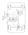
- FIG. 21 is a block diagram for explaining an application example of a power storage device according to an embodiment of the present technology.
- First embodiment (one example of a power storage device)
- Second embodiment (another example of a power storage device)
- Embodiments and the like described hereafter are preferred concrete example of the present technology, and contents of the present technology are not limited to these embodiments and the like. Furthermore, effects described in the present specification are strictly examples and not limited. Furthermore, it is not denied that effects different from exemplified effects exist.
- FIG. 1 is a perspective view illustrating an exterior view of the power storage device.
- FIG. 2 is a sectional view taken along a line A-A′ in FIG. 1 .
- illustration of members other than an armoring case, a battery case, battery cells, and a partition plate is omitted.
- FIG. 3 illustrates an outline of an electric configuration of a power storage device according to the first embodiment of the present technology.
- FIG. 4 illustrates an outline of an electric configuration of a power storage device according to the first embodiment of the present technology.
- a power storage device 1 includes an armoring case 20 .
- the armoring case 20 is a casing taking the shape of a substantially rectangular parallelepiped and including a front face unit 20 a , a rear face unit 20 b , a top face unit 20 c , a bottom face unit 20 d , and two side face units 20 e and 20 f .
- a material of the armoring case 20 it is desirable to use a material having a high thermal conductivity and a high emissivity.
- each of the front face unit 20 a , the rear face unit 20 b , the top face unit 20 c , the bottom face unit 20 d , and the two side face units 20 e and 20 f included in the armoring case 20 is a plate-like body or a body obtained by shape machining on a plate-like body.
- the plate-like body is, such as, a metal plate of aluminum, an aluminum alloy, copper, or a copper alloy.
- the front face unit 20 a included in the casing is covered by a protection cover 21 .
- the protection cover 21 includes an insulation material having an electric insulation property such as, a resin. It is possible to secure insulation between a connection member, which electrically connects a plurality of power storage devices 1 such as, bus bars, and the front face unit 20 a , by covering the front face unit 20 a with the protection cover 21 including a material having insulation.
- the power storage device 1 can be placed with a face other than the front face unit 20 a set as a bottom face. In other words, the power storage device 1 can be placed with the rear face unit 20 b , the top face unit 20 c , the bottom face unit 20 d , the side face unit 20 e , or the side face unit 20 f set as the bottom face.
- a battery unit 51 , a battery unit 52 , and a board and the like on which a control circuit block and the like are mounted are accommodated in the armoring case 20 of the power storage device 1 .
- Each of the battery unit 51 and the battery unit 52 includes a battery block group 10 including a plurality of battery cells 10 a and members, such as partition plates 93 inserted between lines each including a plurality of battery cells 10 a arranged in a line form and a connection terminal unit 91 (not illustrated in FIG. 2 ) which electrically connects a plurality of battery cells 10 a , accommodated in a battery case 61 including a top case 61 a and a bottom case 61 b.
- the side face unit 20 e on this side and the side face unit 20 f on a back side in the armoring case 20 are, for example, rectangular shaped plate-like bodies.
- the battery unit 51 is fixed to the side face unit 20 f
- the battery unit 52 is fixed to the side face unit 20 e .
- the battery unit 51 is fixed to the side face unit 20 f by, for example, inserting a plurality of convex shaped fitting units provided on the side face unit 20 f into a plurality of hole-shaped fitting units provided on a bottom face unit of the bottom case 61 b .
- the battery unit 52 is fixed to the side face unit 20 e by inserting a plurality of convex or the like shaped fitting units provided on the side face unit 20 e into a plurality of hole-shaped fitting units provided on a bottom face unit of the bottom case 61 b.
- the battery block group 10 includes, for example, a plurality of battery blocks connected in series, and one battery block includes a plurality of battery cells 10 a connected in parallel.
- the battery cell 10 a is a secondary battery such as, a cylindrical lithium ion secondary battery.
- the battery cell 10 a is not limited to the lithium ion secondary battery.
- the battery unit 51 and the battery unit 52 are two-stage stacked in the horizontal direction in a vertical mounting state with a bottom face unit and a top face unit of the battery case 61 being directed in the horizontal direction, and accommodated in the armoring case 20 .
- a gap S is provided between opposite faces of the battery unit 51 and the battery unit 52 which are stacked.
- battery blocks B 1 to B 16 each including fourteen battery cells 10 a connected in parallel are connected in series and accommodated in the battery unit 51 and the battery unit 52 .
- a battery block group 10 including the battery blocks B 1 to B 8 is accommodated in the battery unit 51 .
- a battery block group 10 including the battery blocks B 9 to B 16 is accommodated in the battery unit 52 .
- the number of battery cells 10 a included in each battery block is not limited to fourteen.
- the number of battery blocks included in each battery block group 10 is not limited to the above-described number, either.
- connection terminal unit 91 which is a member for connection having electrical conductivity, is used to connect battery cells 10 a to each other and to connect battery cells 10 a to adjacent battery blocks in series and/or in parallel.
- the connection terminal unit 91 is a plate-like body including a material having electrical conductivity, such as, metal. Details of a configuration of the connection terminal unit 91 will be described later.
- the battery blocks B 1 to B 16 are connected to a control circuit block (hereafter referred to as control block) and controlled to charge or discharge by the control block.
- the charging and discharging are performed via an external positive electrode terminal 4 and an external negative electrode terminal 5 .
- the control block is provided in the power storage device 1 in order to monitor the voltage, current and temperature of the battery cells 10 a .
- Information from the control block is transmitted to an external controller by communication.
- the external controller performs charge management, discharge management, and management for deterioration suppression and the like.
- the control block monitors the voltage of each battery block, converts the detected voltage to a digital signal, and transmits the digital signal to a control box ICNT which is the external controller.
- the control block may detect the temperature of each battery block in addition to the voltage, convert the temperature to digital data, and transmit the digital data to the control box ICNT.
- FIG. 4 illustrates an example of the control block. As illustrated in FIG. 4 , a voltage across sixteen battery blocks B 1 to B 16 connected in series and a voltage across each battery block are detected. A multiplexer 8 (MUX 8 ) is provided to output the voltage across the battery blocks B 1 to B 16 and the voltage across each battery block in order.
- MUX 8 multiplexer 8
- the MUX 8 switches the channel in accordance with, for example, a predetermined control signal, and selects one analog voltage data out of n analog voltage data.
- the analog voltage data selected by the MUX 8 is supplied to an Analog to Digital Converter (ADC) (A/D converter) 6 .
- ADC Analog to Digital Converter
- the ADC 6 converts the analog voltage data supplied from the MUX 8 to digital voltage data.
- the analog voltage data is converted to digital voltage data in the range of 14 to 18 bits.
- the digital voltage data from the ADC 6 is supplied to a communication unit COM 1 .
- the communication unit COM 1 is controlled by a control unit 7 to perform communication with an external device connected through a communication terminal.
- the communication unit COM 1 performs communication with another power storage device MO through the communication terminal, and performs communication with the control box ICNT through the communication terminal.
- the communication unit COM 1 receives a control signal from the control box ICNT through the communication terminal. In this way, the communication unit COM 1 performs bidirectional communication.
- control unit 7 controls homogenization of voltages of the battery blocks B 1 to B 16 .
- Such control is referred to as cell balance control.
- cell balance control For example, in a case where one battery block among the plurality of battery blocks B 1 to B 16 reaches a discharge voltage that is a lower limit of use, other battery blocks that still have a remaining capacity exist. In a case where charging is performed the next time, other battery blocks that still had a remaining capacity reach an upper limit charge voltage earlier and consequently charging is not performed up to full charge. In order to avoid such unbalance, battery blocks having a remaining capacity are forcibly discharged by turning on a Metal Oxide Semiconductor Field Effect Transistor (MOSFET).
- MOSFET Metal Oxide Semiconductor Field Effect Transistor
- a pulse generator 17 supplies a control pulse to a switch (MOSFET) S 1 provided on a primary side of a flyback transformer T 1 in a module balance control circuit, which controls voltage balance among the power storage device 1 and a plurality of power storage devices MO.
- the pulse generator 17 generates the control pulse in accordance with a control signal supplied from the control unit 7 in a module controller CTN 1 .
- the pulse generator 17 outputs a control pulse subjected to pulse width modulation.
- a MicroController Unit (MCU) in the communication unit COM 1 supplies a control pulse to a switch (MOSFET) S 01 provided on a secondary side of the flyback transformer T 1 .
- the control box ICNT determines a sequence of balance between power storage device on the basis of voltage information of the each power storage device 1 and the power storage devices MO.
- the control box ICNT transmits whether to perform charging or discharging for balance between power storage devices, to the MCU in each power storage device.
- the MCU supplies a control signal directly to the secondary side of the flyback transformer or transmits a control signal to the primary side of the flyback transformer T 1 by using insulation communication via an insulation unit ISC 1 .
- a temperature detection unit 15 includes a temperature detection element such as a thermistor.
- Analog temperature data T which indicates the temperature of each of the battery blocks B 1 to B 16 detected by the temperature detection unit 15 is supplied to a cell temperature multiplexer 16 (MUX 16 ).
- MUX 16 cell temperature multiplexer 16
- analog temperature data T 1 which indicates the temperature of the battery block B 1 is supplied to the MUX 16 .
- Analog temperature data T 2 which indicates the temperature of the battery block B 2 is supplied to the MUX 16 .
- analog temperature data T 3 to analog temperature data T 16 respectively indicating the temperatures of the battery block B 3 to the battery block B 16 are supplied to the MUX 16 .
- the MUX 16 switches a channel in accordance with a predetermined control signal, and selects one analog temperature data T out of sixteen analog temperature data T 1 to analog temperature data T 16 . Further, one analog temperature data T selected by the MUX 16 is supplied to the ADC 6 .
- a current detection unit 9 detects values of currents flowing through a plurality of battery blocks B 1 to B 16 .
- the current detection unit 9 includes, for example, a current detection resistor 9 a and a current detection amplifier 9 b .
- Analog current data which indicates a value of voltage across the current detection resistor 9 a is detected by the current detection resistor 9 a .
- the analog current data is detected at all times no matter whether charging or discharging is being performed.
- the analog current data may be detected at a predetermined period.
- the detected analog current data is supplied to the current detection amplifier 9 b .
- the supplied analog current data is amplified by the current detection amplifier 9 b .
- the amplified analog current data is supplied to the ADC 6 .
- the ADC 6 converts the analog current data supplied from the current detection amplifier 9 b to digital current data.
- the analog current data is converted to the digital current data by the ADC 6 , and the digital current data is output.
- the module controller CTN 1 determines that a discharge overcurrent state is brought about and performs control to cause a switch (not illustrated) to assume an open state (a state in which the current is interrupted).
- the module controller CTN 1 performs control to cause a switch (not illustrated) to assume an open state (a state in which the current is interrupted).
- the insulation unit ISC 1 has a function of giving insulation between the communication unit COM 1 and the module controller CTN 1 .
- reference potential of a power supply of the communication unit COM 1 and reference potential of a power supply of the module controller CTN 1 are separated from each other and are made independent from each other.
- the insulation unit ISC 1 has a function of supplying a power supply voltage to the module controller CTN 1 and a function of serving as a transmission medium of bidirectional communication.
- a system of bidirectional communication performed through the insulation unit ISC 1 it is possible to use standards of CAN.
- a system of power transmission performed through the insulation unit ISC 1 an electromagnetic induction system, a magnetic resonance system, a radio wave reception system and the like can be used.
- a non-contact IC card technology is used.
- an antenna coil in a reader/writer and an antenna coil in a card are magnetic-flux-coupled, and communication and power transmission are performed between the reader/writer and the card.
- a system of performing Amplitude Shift Keying (ASK) modulation on a carrier wave having a frequency of 13.56 kHz is used, and communication is performed at a velocity of 212 or 424 kbps.
- the insulation unit ISC 1 is provided in accordance with specifications similar to those of the non-contact IC card system.
- the insulation unit ISC 1 is adapted to perform communication and power transmission between antennas (coils) formed in different layers of a multilayer printed circuit board.
- FIG. 5 is an exploded perspective view illustrating a configuration of a front end unit of the power storage device.
- FIG. 6 is a perspective view illustrating a member detached together with the front face unit.
- FIG. 7 is a perspective view illustrating a state in which the front face unit is detached.
- the front face unit 20 a is covered by the protection cover 21 .
- a space which accommodates a component group including a board and the like is secured.
- a component group including at least an external communication board 45 and an output terminal board 44 illustrated in FIG. 6 is disposed and fixed in the space.
- the component group includes members including, for example, an output terminal board 44 having an external positive electrode terminal 4 and an external negative electrode terminal 5 serving as output terminals, an external communication board 45 , a fuse 2 , bus bars 47 a 1 to 47 a 3 , a board holding member 49 , and connectors 3 a and 3 b .
- the external communication board 45 and the output terminal board 44 are connected to a main board 46 by connectors (not illustrated).
- the board holding member 49 includes a material having an insulation property such as resin.
- the board holding member 49 plays a role of performing mechanical holding of boards and giving insulation between boards and between a board and components.
- two sub boards 42 are fixed to the battery unit 51 and battery unit 52 , respectively.
- the sub boards 42 are disposed and fixed with one main face of the sub boards opposed to one wall face that is included in four wall faces of the battery case 61 and that is perpendicular to a line direction of a battery line and a unit of the main face of the sub boards in close contact with the one wall face.
- the control block including a monitor and control circuit illustrated in FIG. 3 and FIG.
- a component group including a plurality of boards configured separately is disposed in a space between the inner face of the front face unit 20 a and the front wall faces of the battery unit 51 and the battery unit 52 , and the components are connected by connection members such as plate-like members like bus bars 47 a 1 to 47 a 3 and connectors. Therefore, connection between boards can be performed simply.
- Such a power storage device 1 is efficient and excellent in assembly property. In addition, higher energy because of space saving can be implemented.
- the above-described component group including at least the external communication board 45 and the output terminal board 44 fixed to the front face unit 20 a is detached as one body together with the front face unit 20 a .
- a portion including the main board 46 disposed on a rear side as compared with the component group faces to external from an opening of the armoring case 20 with the front face unit 20 a removed, as illustrated in FIG. 7 . It becomes possible to put hands into the inside from the opening to perform works such as maintenance work of the main board 46 or take out the main board 46 swiftly.
- the external positive electrode terminal 4 and the external negative electrode terminal 5 provided to charge and discharge the power storage device 1 are exposed to the external through openings provided through the protection cover 21 and the front face unit 20 a.
- windows 25 a , 25 b , 26 a and 26 b which are close to each other are formed through the protection cover 21 and the front face unit 20 a .
- the windows 25 a , 25 b , 26 a and 26 b are covered by a short bar 11 at the time of operation of the power storage device 1 .
- Connectors 3 a and 3 b are provided inside the windows 25 a and 25 b formed on the front face unit 20 a .
- a terminal on a positive electrode side of the battery blocks B 1 to B 16 connected in series is connected to the connector 3 a via the fuse 2 which is a current interruption element.
- the other connector 3 b is provided near the connector 3 a .
- the connector 3 b is connected to the external positive electrode terminal 4 .
- a terminal on a negative electrode side of the battery blocks B 1 to B 16 is connected to the external negative electrode terminal 5 .
- the short bar 11 which can be freely inserted and removed is provided as a connection unit for the connectors 3 a and 3 b .
- a conductive plate of the short bar 11 is bent to have a pair of plate-like projections 12 a and 12 b , and a base portion of the conductive plate is attached to one face of a support plate 13 .
- a cover 14 is formed by extending one end of the support plate 13 .
- a knob 15 is formed on the other face of the support plate 13 .
- the support plate 13 having the cover 14 and the knob 15 is, for example, a molded article of synthetic resin.
- Each of the connectors 3 a and 3 b has two spring contact plates disposed to be opposite to each other.
- the plate-like projections 12 a and 12 b of the short bar 11 are inserted into gaps each between the two spring contact plates through the windows 25 a and 25 b .
- the windows 26 a and 26 b are blocked up by the cover 14 which is integral with the support plate 13 of the short bar 11 . Since the plate-like projections 12 a and 12 b are sandwiched between the two spring contact plates of the connectors 3 a and 3 b , respectively, it is possible to hold the insertion state of the short bar 11 into the connectors 3 a and 3 b.
- the connector 3 a and the connector 3 b are connected (made conductive) to each other by the short bar 11 , by inserting the plate-like projections 12 a and 12 b of the short bar 11 into the gaps of the connectors.
- the connector 3 a and the connector 3 b are disconnected (made nonconductive) from each other by pulling the plate-like projections 12 a and 12 b of the short bar 11 from the gaps of the connectors. In this way, it is possible to switch between a connection state in which the short bar 11 is inserted into the connectors 3 a and 3 b and a non-connection state in which the short bar 11 is pulled out from the connectors 3 a and 3 b.
- An electronic component 28 to be used for setting or connection is disposed on the inside of the windows 26 a and 26 b formed through the front face unit 20 a .
- the electronic component 28 is, for example, a slide switch, a rotary switch, a JTAG connector, and the like.
- an address for the power storage device 1 is set by using the rotary switch. In other words, it is made possible to connect and use a plurality of power storage devices 1 . In a case where a plurality of power storage devices 1 is connected, an address for identification is set to each of the power storage devices.
- the external controller performs control processing on the basis of the address.
- the slide switch is used to increase addresses specified by the rotary switch.
- the JTAG connector is a standard connector proposed by Joint European Test Action (JTAG). Test data is input and output through the JTAG connector to inspect a Micro Processing Unit (MPU), Integrated Circuits (ICs) and the so forth within the case. Furthermore, rewriting on firmware of the internal MPU is performed through the JTAG connector.
- MPU Micro Processing Unit
- ICs Integrated Circuits
- firmware of the internal MPU is performed through the JTAG connector.
- electronic components, switching components, connectors and the like besides the above-described elements may be used.
- the cover 14 closes the windows 25 a , 25 b , 26 a and 26 b in front of an operation face of electronic components. In other words, in the connection state, access to the electronic components is obstructed.
- the windows in front of the operation face of the setting unit are opened and, for example, an address of the power storage device 1 can be set by operating the operation face through the windows 25 a , 25 b , 26 a , and 26 b.
- a connector 27 which is a communication terminal to be used in communication with the external controller is provided in the power storage device 1 .
- the control block is provided in the power storage device 1 to monitor the voltage, current and temperature of batteries. Information from the control block is transmitted to the external controller by communication.
- the external controller performs charging management, discharging management, and management for degradation suppression and the like.
- a serial interface As for the communication with the external controller performed via the connector 27 , for example, a serial interface is used.
- a serial interface specifically a System Management Bus (SM bus) or the like is used.
- SM bus System Management Bus
- I2C bus can be used.
- the I2C bus is synchronous serial communication in which communication is performed by using two signal lines, i.e., SCL (serial clock) and bidirectional SDA (serial data).
- FIG. 9 is an exploded perspective view illustrating a configuration example of the battery unit.
- the battery block group 10 including a plurality of battery cell blocks, the partition plates 93 , the connection terminal units 91 , and positive electrode insulation sheets 92 are accommodated in a battery case 61 including the top case 61 a and a bottom case 61 b .
- the battery unit 52 has a configuration similar to that of the battery unit 51 .
- the configuration of the battery unit 51 will be described in detail, and detailed description of the configuration of the battery unit 52 will be omitted.
- the battery case 61 includes the top case 61 a and the bottom case 61 b .
- the battery case 61 is, for example, a molded article of resin having an electric insulation property.
- FIG. 10 is a perspective view illustrating a configuration example of the top case 61 a .
- the top case 61 a includes a top face unit and a wall unit erected around the top face part.
- a plurality of openings 71 where the connection terminal units 91 disposed on a terminal face of a plurality of battery cells 10 a is exposed is provided on the top face unit of the top case 61 a .
- a plurality of holes 72 into which projection units 93 a of the partition plates 93 described later are fit is provided on the top face unit of the top case 61 a .
- a plurality of fitting units 62 is projected from the top face unit of the top case 61 a .
- the bottom case 61 b includes a bottom face unit and a wall unit erected around the bottom face unit. Although illustration is omitted, four hollow structures are provided in the center of the bottom face unit in a line form. In a state in which the bottom case 61 b is combined with the top case 61 a , the four hollow structures are fitted to hollow structures 70 of the top case 61 a .
- Each of the hollow structures of the bottom case 61 b is, for example, a structure that has a hollow structure, and takes a hollow cylinder shape, and has an opening on the upper face and has a hole in the center of the bottom face.
- the hole is fitted to the projection unit provided on the side face unit 20 f , and screwing is performed as occasion demands, and the battery unit 51 is fixed to the side face unit 20 f .
- a plurality of openings 71 where connection terminal units 91 b are exposed is provided on the bottom face unit of the bottom case 61 b , in the same way as the top face unit of the top case 61 a .
- a plurality of holes 72 is provided on the bottom face unit of the bottom case 61 b to fit to the projection units 93 a of the partition plates 93 which will be described later.
- FIG. 11 is a perspective view illustrating a state before the two battery units are combined.
- the top face unit of the top case 61 a of the battery unit 51 and the top face unit of the top case 61 a of the battery unit 52 are opposed to each other, and the fitting units 62 projected on corresponding one top face unit are fitted to the fitting units 62 projected on the other top face unit, as illustrated in FIG. 11 .
- the fitting units 62 include, for example, convex shaped fitting units 62 a and concave shaped fitting units 62 b .
- the fitting units 62 are arranged in a line form and disposed to have the convex shaped fitting units 62 a and the concave shaped fitting units 62 b which are line symmetrical about a center line along a longitudinal direction of the top face unit serving as a symmetry axis.
- a plurality of fitting units 62 is projected from the top face unit of the top case 61 a .
- the top face unit of the top case 61 a includes convex portions including the fitting units 62 and a plane including portions other than the fitting units 62 .
- the erected fitting units 62 a and 62 b are brought into contact each other and fitted as illustrated in FIG. 12A .
- the gap S having an interval corresponding to heights of the fitted fitting units 62 a and 62 b is formed between planes of the top face units of the opposed top cases 61 a of the battery unit 51 and the battery unit 52 .
- This gap S improves emission of high temperature gas generated by the battery cell 10 a to the external when a safety mechanism or the like of the battery cell 10 a is activated at the time of abnormality. As a result, thermal emission is improved, and consequently the safety can be improved.
- a configuration is taken to prevent openings 71 (indicated by dashed lines) where connection portions between the connection terminal unit 91 of the battery unit 51 and the terminal face of the battery cell 10 a are exposed and openings 71 (indicated by solid lines) where connection portions between the connection terminal unit 91 of the battery unit 52 and the terminal face of the battery cell 10 a from overlapping in the stacking direction as illustrated in FIG. 12B .
- a position where high temperature gas generated by the battery cell 10 a in the battery unit 51 which is one of the opposed battery units is directly applied is deviated from the battery cell 10 a in the battery unit 52 which is the other of the opposed battery units.
- the battery block group 10 has, for example, a configuration in which battery lines each including a plurality of battery cells 10 a arranged in a straight line form is arranged in parallel in a direction substantially perpendicular to the line direction of the battery line.
- Each of the battery lines includes, for example, fourteen batteries.
- the plurality of battery cells 10 a included in the battery block group 10 is connected electrically by the connection terminal unit 91 .
- each of battery blocks B 1 to B 8 is a battery line including a plurality of battery cells 10 a connected in parallel.
- the battery block group 10 is formed by connecting the battery blocks B 1 to B 8 in series.
- the battery block group 10 accommodated in the battery case 61 of the battery unit 52 also has a similar configuration.
- the battery line L 1 to the battery line L 8 become battery blocks B 9 to B 16 each including a plurality of battery cells 10 a connected in parallel.
- the battery block group 10 is formed by connecting the battery blocks B 9 to B 16 in series.
- a plurality of battery lines (battery lines L 1 to L 8 ) each having a plurality of battery cells 10 a connected in parallel is arranged in a direction substantially perpendicular to the line direction and connected in series. Accordingly, the current path can be rectified in a single direction (for example, a direction substantially perpendicular to the line direction of the battery lines), and the total length of the current path can be shortened. As a result, an increase of the resistance value can be suppressed.
- the battery line L 1 and the battery line L 2 are arranged to be opposed to each other
- the battery line L 2 and the battery line L 3 are arranged to be opposed to each other
- the battery line L 3 and the battery line L 4 are arranged to be opposed to each other
- the battery line L 4 and the battery line L 5 are arranged to be opposed to each other
- the battery line L 5 and the battery line L 6 are arranged to be opposed to each other
- the battery line L 7 and the battery line L 8 are arranged to be opposed to each other.
- each of a plurality of battery cells 10 a included in each battery line is disposed to have a positive electrode terminal face on its top face and a negative electrode terminal face on its bottom face.
- each of a plurality of battery cells 10 a included in each battery line is disposed to have a negative electrode terminal face on its top face and a positive electrode terminal face on its bottom face.
- a plurality of battery cells 10 a included in each battery line is disposed side by side in a straight line form and in a closed contact state.
- fourteen battery cells 10 a included in each battery line are disposed side by side in a straight line form and in a closed contact state.
- a plurality of battery cells 10 a included in each battery line is disposed to make it possible for a space substantially corresponding to one battery cell 10 a to be provided between two sets of battery cells 10 a disposed side by side in a straight line form and in a closed contact state.
- the space substantially corresponding to one battery is preferred to be provided on a position, for example, opposed to a center of the adjacent and opposed battery line L 2 , L 4 , L 6 or L 8 .
- each battery line fourteen battery cells 10 a included in each battery line are disposed to make it possible for a space corresponding to one battery cell 10 a to be provided between two sets of seven battery cells 10 a disposed side by side in a straight line form and in a closed contact state.
- the space substantially corresponding to one battery is provided on a position, for example, opposed to a center of the adjacent and opposed battery line L 1 , L 3 , L 5 or L 7 .
- a hollow structure (not illustrated) of the bottom case 61 b and the hollow structure 70 of the top case 61 a opposed to the hollow structure are fitted in the space substantially corresponding to one battery cell 10 a .
- a hole is provided on the bottom face of the hollow structure of the top case 61 a , a projection of the side face unit 20 f is fitted into the hole and screwing is performed as occasion demands, and the battery unit 51 is fixed to the side face unit 20 f . Since a fixing unit to the side face unit 20 f is provided near the center of the battery unit 51 , it is possible to prevent swelling out from occurring near the center of the battery unit 51 by deviation or the like of the battery cells 10 a included in the battery block group 10 .
- the straw bag stacking arrangement includes an arrangement in which substantially centers of end faces of two adjacent battery cells 10 a in one line and substantially a center of a battery cell 10 a which is in another line adjacent to the one line and which comes in between the two adjacent battery cells 10 a in the one line takes the shape of a substantially regular triangle.
- the straw bag stacking arrangement it is possible to accommodate a larger number of battery cells 10 a in the battery case 61 having a limited space. Therefore, the number of battery cells per area can be increased and the energy density of the power storage device 1 can be improved.
- connection terminal unit 91 functioning as a jointing member which electrically connects a plurality of battery cells 10 a is provided on terminal faces of a plurality of battery cells 10 a .
- the connection terminal unit 91 is, for example, a plate-like body or the like having a plane shape such as, a rectangular shape.
- two connection terminal units 91 a and three connection terminal units 91 b are arranged in parallel in a direction substantially perpendicular to the line direction of the battery line as the connection terminal unit 91 .
- a plurality of holes 96 is provided through the connection terminal unit 91 b to make it possible to insert the projection units 93 a of the partition plates 93 through.
- connection terminal unit 91 a is electrically joined to terminal faces of a plurality of battery cells 10 a included in one battery line.
- connection terminal unit 91 b is electrically joined to terminal faces of a plurality of battery cells 10 a included in two adjacent battery lines.
- connection terminal unit 91 a is electrically joined to positive electrode terminals of a plurality of battery cells 10 a included in the battery line L 1 .
- the connection terminal unit 91 a is electrically joined to positive electrode terminals of a plurality of battery cells 10 a included in the battery line L 8 .
- the connection terminal unit 91 b is electrically joined to negative electrode terminals of a plurality of battery cells 10 a included in the battery line L 2 and positive electrode terminals of a plurality of battery cells 10 a included in the battery line L 3 .
- the connection terminal unit 91 b is electrically joined to negative electrode terminals of a plurality of battery cells 10 a included in the battery line L 4 and positive electrode terminals of a plurality of battery cells 10 a included in the battery line L 5 .
- the connection terminal unit 91 b is electrically joined to negative electrode terminals of a plurality of battery cells 10 a included in the battery line L 6 and positive electrode terminals of a plurality of battery cells 10 a included in the battery line L 7 .
- the joining method is not especially limited to these methods, but a welding method well-known in the past can be used suitably.
- connection terminal unit 91 a or one connection terminal unit 91 b is connected by using one connection terminal unit 91 a or one connection terminal unit 91 b , and consequently the resistance value can be reduced and the terminal heat generation can be reduced.
- Joining between connection terminal units can be performed by using simple joining. Measurement terminals of the battery cells 10 a can also be made common. Since a plurality of battery cells 10 a included in a battery line are joined by using one connection terminal unit, the assemble work can be simplified and in addition, the work efficiency at the time of assembling can also be improved. In addition, since the joining places can be reduced, the thermal rise of the battery cells 10 a at the time of assembling and joining can be reduced. Heat generated by the battery cells 10 a at the time of charging and discharging can be performed to the connection terminal unit 91 a and the connection terminal unit 91 b and radiated.
- connection terminal units 91 b is arranged in parallel in a direction substantially perpendicular to the line direction of the battery line on a face of inside of the bottom face unit of the bottom case 61 b as the connection terminal unit 91 .
- One connection terminal unit 91 b is electrically joined to terminals on bottom faces of battery cells 10 a included in two adjacent battery lines.
- connection terminal unit 91 b is electrically joined to negative electrode terminals of a plurality of battery cells 10 a included in the battery line L 1 and positive electrode terminals of a plurality of battery cells 10 a included in the battery line L 2 .
- the connection terminal unit 91 b is electrically joined to negative electrode terminals of a plurality of battery cells 10 a included in the battery line L 3 and positive electrode terminals of a plurality of battery cells 10 a included in the battery line L 4 .
- the connection terminal unit 91 b is electrically joined to negative electrode terminals of a plurality of battery cells 10 a included in the battery line L 5 and positive electrode terminals of a plurality of battery cells 10 a included in the battery line L 6 .
- the connection terminal unit 91 b is electrically joined to negative electrode terminals of a plurality of battery cells 10 a included in the battery line L 7 and positive electrode terminals of a plurality of battery cells 10 a included in the battery line L 8 .
- connection terminal units 91 b shown in FIG. 13 are electrically joined to negative electrode terminals of a plurality of battery cells 10 a that are disposed in the direction of lines L 1 to L 7
- the connection terminal units 91 b may alternatively be joined to a plurality of battery cells that are disposed in a direction diagonal to the direction of lines L 1 to L 7 .
- FIG. 14 is a perspective view illustrating a configuration example of the connection terminal unit.
- FIG. 15 is a perspective view in which a portion of the connection terminal unit is enlarged.
- a plurality of holes 96 are provided through the connection terminal unit 91 b to make it possible to insert the projection units 93 a of the partition plates 93 through.
- the connection terminal unit 91 b is disposed to be parallel in longitudinal direction to the line direction of the battery line.
- one or more cut outs 99 a cut from the side end of the connection terminal unit 91 b are formed in a direction substantially perpendicular to the longitudinal direction of the connection terminal unit 91 b .
- the cut outs 99 a may take a shape of, for example, a rectangle, a wave or a curve. Since the cut out 99 a is formed, heat propagation in the connection terminal unit 91 b can be suppressed in a case where the battery cells 10 a generate heat abnormally.
- the connection terminal unit 91 b is blown with the cut out 99 a as a start point by Joule heat generation caused by an electric resistance of the connection terminal unit 91 b , and consequently a current which flows in can be intercepted.
- the cut direction of the cut out 99 a is substantially parallel to a direction in which the current flows (a direction in which battery cell blocks are connected in series), the cut out does not obstruct the current flow at the time of ordinary use. Only at the time of abnormality, the cut out can obstruct current flow in a different direction.
- the connection terminal unit 91 b takes substantially a line symmetrical shape about a center line c along a short direction serving as a symmetry axis.
- the connection terminal unit 91 b has a notch 99 b in a center portion in the longitudinal direction.
- the notch 99 b takes a shape of, for example, a circular arc.
- the notch 99 b in the connection terminal unit 91 b is disposed in a position that overlaps a space substantially corresponding to one battery cell in an even-numbered battery line. Heat propagation can be suppressed by providing the notch 99 b .
- connection terminal unit 91 when a large current is generated by abnormality in the battery, the connection terminal unit 91 is blown with the notch 99 b as a start point and the current can be intercepted.
- the connection terminal unit 91 a also includes similar cut outs 99 a and notch 99 b , and takes a shape which is substantially line symmetrical about a center line along a short direction serving as a symmetry axis.
- the connection terminal unit 91 a also brings about an action and effect similar to those described above.
- a positive electrode insulation sheet 92 is piled on positive electrode terminal faces of the battery cells 10 a included in the battery block group 10 .
- the positive electrode insulation sheet 92 is piled on the positive electrode terminal faces of the battery cells 10 a having positive electrode terminal faces on top faces.
- the positive electrode insulation sheet 92 is piled on the positive electrode terminal faces of a plurality of battery cells 10 a included in each battery line.
- the positive electrode insulation sheet 92 is formed of a material having an electrical insulation property such as a resin material having an electrical insulation property. A plurality of openings is provided on the positive electrode insulation sheet 92 to make it possible to insert a plurality of convex shaped positive electrode terminals therein.
- Positive electrode terminals are respectively inserted into a plurality of openings of the positive electrode insulation sheet 92 , and the positive electrode terminals are exposed from the openings of the positive electrode insulation sheet 92 .
- the positive electrode terminals exposed from the openings of the positive electrode insulation sheet 92 are electrically joined to the connection terminal unit 91 a or the connection terminal unit 91 b .
- faces around the positive electrode terminals are covered by the positive electrode insulation sheet 92 , the faces around the positive electrode terminals are insulated from the connection terminal unit 91 a or the connection terminal unit 91 b.
- the positive electrode insulation sheet 92 on the bottom case 61 b side is provided to prevent short-circuit between faces around convex shaped positive electrode terminals and the connection terminal unit 91 b .
- the positive electrode insulation sheet 92 on the battery case side is piled on positive electrode terminal faces of the battery cells 10 a in the battery line L 2 , the battery line L 4 , the battery line L 6 , and the battery line L 8 .
- FIG. 16 is a schematic perspective view illustrating a configuration of the partition plate and a state before the partition plate is combined with the battery block group.
- the partition plates 93 are inserted between opposed and adjacent battery lines in the battery block group 10 .
- the partition plates 93 are, such as, molded articles of resin including resin having an electric insulation property.
- the partition plates 93 can be attached to and detached from the battery case 61 .
- the partition plate 93 has a plurality of projection units 93 a on its top face and its bottom face.
- the partition plate 93 is attached to the battery case 61 by fitting the projection units 93 a into the holes 72 of the battery case 61 .
- the partition plate 93 is detached from the battery case 61 by detaching the fitted projection units from the holes.
- the plurality of projection units 93 a is provided in predetermined positions of the top face and the bottom face of the partition plate 93 .
- a plurality of projection units 93 a provided on the top face fits into a plurality of holes 72 for positioning of the partition plate provided in predetermined positions of the top case 61 a .
- a plurality of projection units 93 a provided on the bottom face fits into a plurality of holes 72 for positioning of the partition plate provided in predetermined positions of the bottom case 61 b .
- the partition plates 93 are fixed between the top case 61 a and the bottom case 61 b.
- the power storage device according to the second embodiment of the present technology is the same as the power storage device according to the first embodiment except that a configuration of a connection terminal unit differs. Therefore, although the configuration of the connection terminal unit will be described in detail, other configurations are similar to those in the first embodiment, and consequently detailed description of other configurations will be omitted.
- FIG. 17A is a plane view illustrating a configuration example of the connection terminal unit.
- FIG. 17B and FIG. 17C are enlarged plane views obtained by enlarging a portion of the connection terminal unit illustrated in FIG. 17A .
- a plurality of holes 96 through which projection units 93 a of a partition plate 93 is inserted are provided in a connection terminal unit 91 b in the same way as the first embodiment.
- the connection terminal unit 91 b is disposed to have a longitudinal direction parallel to a line direction of a battery line.
- one or more cut outs 99 a cut from side ends of the connection terminal unit 91 b are formed in a direction substantially perpendicular to the longitudinal direction of the connection terminal unit 91 b . Propagation of heat in the connection terminal unit 91 b can be suppressed by forming the cut outs 99 a.
- connection terminal unit 91 b takes substantially a line symmetrical shape about a center line c along a short direction serving as a symmetry axis in the same way as the first embodiment.
- the connection terminal unit 91 b has a notch 99 b in a center portion in the longitudinal direction.
- the notch 99 b takes a shape of, for example, a circular arc.
- connection terminal unit 91 a also includes similar cut outs 99 a and notch 99 b , and takes a shape which is substantially line symmetrical about a center line along a short direction serving as a symmetry axis.
- the connection terminal unit 91 a also brings about an action and effect similar to those described above.
- a plurality of cut outs 99 c is further formed in the connection terminal unit 91 b at intervals along the longitudinal direction of the connection terminal unit 91 b .
- the cut outs 99 c are formed, for example, in a position located on the center side as compared with a joining region where terminal faces of the battery cells 10 a are joined, in the short direction of the connection terminal unit 91 b .
- a region P between the cut outs 99 c functions as a portion to be fused, for example, when the battery cell 10 a generates heat abnormally. Therefore, safety can be further improved. Furthermore, propagation of heat in the connection terminal unit 91 b can be further suppressed.
- a portion fused to intercept a current, such as a region between the cut outs 99 c is referred to as fusing unit.
- a length of the cut outs 99 c and a length between the cut outs 99 c are referred to as length L′ of the cut outs 99 c and length w′ between the cut outs 99 c , as illustrated in FIG. 17C .
- a length of the fusing unit corresponds to the length L′ of the cut outs 99 c
- a width of the fusing unit corresponds to the length w′ between the cut outs 99 c.
- the plurality of cut outs 99 c is formed, for example, to cause the fusing unit, which is a region between the cut outs 99 c , to become at least any of the following states. That is, for example, the fusing unit is located on a center side as compared with a joining region where terminal faces of the battery cells 10 a are joined, in the short direction of the connection terminal unit 91 b . For example, one fusing unit is disposed for every one joining region where a terminal face of one battery cell 10 a is joined. For example, a plurality of fusing units is located on a straight line along the longitudinal direction of the connection terminal unit 91 b .
- a line including a plurality of fusing units is arranged on a straight line along the longitudinal direction of the connection terminal unit 91 b , and two lines are arranged in the short direction of the connection terminal unit 91 b .
- the line of fusing units arranged in the two lines is located on the center side as compared with the joining region where terminal faces of the battery cells 10 a are joined, in the short direction of the connection terminal unit 91 b.
- the cut outs 99 c may be formed to be linked to the hole 96 .
- the cut outs 99 c may be formed to be linked to the cut out 99 a .
- the cut outs 99 c may be linked neither to the hole 96 nor to the cut out 99 a .
- the shape of the cut outs 99 c may be a straight line shape, a shape including a curve, or a shape including an angle.
- the cut outs 99 c similar to those in the connection terminal unit 91 b may be connected in the connection terminal unit 91 a as well.
- connection terminal unit 91 b it is further desirable to adjust the shape, material, and the like of the fusing unit to cause an electrical resistance Rt of the fusing unit to satisfy Expression (1) below.
- the reason is because it becomes possible to fuse the fusing unit more certainly in a case where heat is generated abnormally, and a current can be let flow without temperature of the connection terminal unit 91 b becoming high at the time of ordinary use.
- T C is a temperature of environment where the power storage device is in use (atmosphere temperature).
- a temperature corresponding to environment temperature at which the power storage device is in use is substituted into T C .
- a lower limit temperature of environment temperature depending upon specifications of the power storage device may be substituted.
- a melting point depending upon a conductive material included in the connection terminal unit 91 b is substituted into T 1 .
- a conductive material such as copper is used as a material of the connection terminal unit 91 b .
- the short-circuit current I 1 is magnitude of a current (short-circuit current) that flows at the time of short-circuit. For example, three pairs of two measurement points are provided on a route through which the short-circuit current flows. A current value is obtained by measuring a resistance value between measurement points of each pair and measuring a voltage at the time of short-circuit. A value of the short-circuit current I 1 can be obtained by calculating an average value of three current values.
- the thermal capacity C is a thermal capacity of the fusing unit, and found according to specific heat c [J/g ⁇ K] of the fusing unit ⁇ mass [g] of the fusing unit.
- the thermal capacity C can be calculated by substituting specific heat of the fusing unit depending upon the material of the connection terminal unit and a value depending upon the mass of the fusing unit into this expression.
- a maximum current of the power storage device (a maximum current at the time of ordinary use) is substituted into I 0 .
- An upper limit value of temperature rise of the connection terminal unit (the power storage device) in a case where the maximum current flows is substituted into ⁇ T 0 .
- values depending upon specifications of the power storage device are substituted into them.
- a temperature change ⁇ T [K] for t seconds in a case where a current I [A] has flown can be specified by the following expression.
- the electrical resistance R t of the fusing unit and the thermal resistance R ⁇ of the fusing unit can be specified by the following expressions.
- the heat transfer unit in the connection terminal unit means a portion to which heat from the fusing unit is transferred.
- the thermal resistance R ⁇ is set to be, for example, thermal resistance at the time when heat generated in the fusing unit is transferred as far as an end of the connection terminal unit.
- the length from the fusing unit to the end of the connection terminal unit in the heat transfer direction is set to be the length of the heat transfer unit in the connection terminal unit.
- Rtmin is an electrical resistance value that causes the fusing unit to be fused in the specified time t 1 at the time of abnormality.
- Rtmax is an electrical resistance value that causes no problem in ordinary use (an electrical resistance value that does not fuse the fusing unit even if a current of a maximum current value is continued to be flown through the fusing unit within a range of specifications).
- Rtmin and Rtmax will be specified respectively by using Expression (c).
- Width w 0.0054 [m]
- the value of R tmax becomes 0.26 [m ⁇ ] as described above.
- the line a in FIG. 19 is the same as the line a in FIG. 18 .
- numerical values, structures, shapes, materials, raw materials, manufacture processes and the like described in the above-described embodiment and examples are nothing but examples.
- numerical values, structures, shapes, materials, raw materials, manufacture processes and the like differing from them may be used.
- a plurality of projection units and a plurality of holes may be one projection unit and one hole.
- the number of battery units accommodated in the armoring case 20 is two has been described.
- the number of battery units accommodated in the armoring case 20 is not limited to two.
- the number of battery units accommodated in the armoring case may be one or three or more.
- battery units may be three or more-stage stacked in the horizontal direction in a vertical mounting state with a top face unit of the top case 61 a being directed in the horizontal direction, and accommodated in the armoring case 20 .
- battery units may be three or more-stage stacked in the horizontal direction in a transversal mounting state with a top face unit of the top case 61 a being directed in the vertical direction, and accommodated in the armoring case 20 .
- the bottom face unit of the bottom case 61 b may have a configuration similar to that of the top face unit of the top case 61 a .
- two battery units 51 and 52 two or more-stage stacked in the horizontal direction with the top face unit of the top case 61 a and the bottom face unit of the bottom case 61 b being directed in the vertical direction may be accommodated in the armoring case 20 .
- the power storage device can have the following configurations.
- a power storage system comprising:
- each battery line comprising a plurality of battery cells arranged in a first direction
- connection terminal unit electrically connected to terminal faces of each battery cell of a group of the battery cells
- connection terminal unit wherein at least one cut out is formed in the connection terminal unit.
- connection terminal unit is electrically connected to terminals on bottom faces of battery cells included in two adjacent battery lines.
- connection terminal unit is a plate-like body having a rectangular shape.
- connection terminal unit comprises a plurality of holes.
- connection terminal unit further includes additional cut outs formed at intervals along a longitudinal direction of the connection terminal unit.
- T 1 is a melting point in degrees Kelvin of the fusing unit
- T C is a temperature in degrees Kelvin of an environment in which the power storage device is used
- I 1 is a short-circuit current in Amperes flowing at a time of short-circuit
- C is a thermal capacity in Joules per degree Kelvin of the fusing unit
- a power storage device comprising:
- a plurality of battery lines each including a plurality of battery cells arranged in a line form in a line direction
- a battery block group obtained by arranging the plurality of battery lines in parallel in a direction substantially perpendicular to the line direction of the battery lines and
- connection terminal unit joined to terminal faces of a plurality of battery cells included in at least one of the battery lines, the connection terminal unit disposed to be parallel to the line direction of the battery lines,
- connection terminal unit includes a fusing unit to be fused to intercept a current
- T 1 is a melting point in degrees Kelvin of the fusing unit
- T C is a temperature in degrees Kelvin of an environment in which the power storage device is used
- I 1 is a short-circuit current in Amperes flowing at a time of short-circuit
- C is a thermal capacity in Joules per degree Kelvin of the fusing unit
- a power storage system comprising:
- a power generation device that generates power from renewable energy
- the power storage device is charged by the power generation device.
- a power storage system comprising:
- the power storage device supplies power to the at least one electronic device.
- a power storage system for a house comprising:
- the power generation device supplies power to the power storage device and a power consumption device
- control device controls the amount of power supplied to the power storage device from the concentrated electric power system and the power generation device.
- a power storage system for a vehicle comprising:
- the power driving force conversion device is activated by power from the power storage device
- An electric vehicle comprising:
- control device which performs information processing concerning vehicle control on the basis of information concerning the power storage device.
- a power storage device comprising:
- a first battery unit including a first battery block group
- a second battery unit including a second battery block group
- each of the first battery block group and the second battery block group comprises a plurality of battery lines each including a plurality of battery cells arranged in a first direction, the plurality of battery lines arranged in parallel in a second direction substantially perpendicular to the first direction, wherein each of the first battery unit and the second battery unit comprises a fitting unit projected from a top face unit of the battery unit, wherein the fitting unit of the first battery unit is opposed to and in contact with the fitting unit of the second battery unit, and a gap is formed between the first battery unit and the second battery unit.
- connection terminal unit for electrically connecting a plurality of battery cells, comprising at least one cut out formed in the connection terminal unit.
- the present technology is a power storage system in which the above-described power storage device is charged by a power generation device that generates power from renewable energy.
- the present technology is a power storage system that has the above-described power storage device and that supplies power to electronic devices connected to the power storage device.
- These electronic devices and a power system are executed as, for example, a power supply system in a house.
- the electronic devices and the power system are executed as, for example, a power supply system in a house.
- the electronic devices and the power system are executed as a system that performs efficient supply of power in cooperation with an external power supply network.
- the present technology is an electric vehicle including a conversion device which is supplied with power from the above-described power storage device and which converts the power to drive force of the vehicle, and a control device which performs information processing concerning vehicle control on the basis of information concerning the power storage device.
- the present technology is a power system including a power information transmission/reception unit which transmits/receives a signal to/from another device via a network, and exercising charging/discharging control of the above-described power storage device on the basis of information received by the transmission/reception unit.
- the present technology is a power system which is supplied with power from the above-described power storage device or which supplies power to the power storage device from the power generation device or the power network.
- a power storage system 100 for a house 101 power is supplied from a concentrated electric power system 102 such as thermal power generation 102 a , atomic power generation 102 b , and hydraulic power generation 102 c to a power storage device 103 via a power network 109 , an information network 112 , a smart meter 107 , a power hub 108 , and the like. Together therewith, power is supplied from an independent power source such as a power generation device 104 to the power storage device 103 . Power supplied to the power storage device 103 is stored. Power used in the house 101 is supplied by using the power storage device 103 . Not only in the house 101 , but also in a building, a similar power storage system can be used.
- the power generation device 104 a power consumption device 105 , the power storage device 103 , a control device 110 which controls respective devices, the smart meter 107 , and sensors 111 which acquire various kinds of information are provided in the house 101 . Respective devices are connected by the power network 109 and the information network 112 .
- a solar cell, a fuel cell, a windmill or the like is used, and generated power is supplied to the power consumption device 105 and/or the power storage device 103 .
- the power consumption device 105 is a refrigerator 105 a , an air conditioner 105 b , a television receiver 105 c , a bath 105 d and the like.
- the electric vehicle 106 is included in the power consumption device 105 .
- the electric vehicle 106 is an electric car 106 a , a hybrid car 106 b , an electric motor cycle 106 c .
- the electric vehicle 106 may be an electrically assisted pedal cycle or the like.
- the power storage device 103 includes a secondary battery or a capacitor.
- the power storage device includes, for example, a lithium ion secondary battery.
- the lithium ion secondary battery may be stationary type or may be that used in the electric vehicle 106 .
- the above-described power storage device 1 according to an embodiment of the present technology can be applied to the power storage device 103 .
- One or a plurality of power storage devices 1 can be applied.
- the smart meter 107 has a function of detecting a used quantity of commercial power and transmitting the detected used quantity to a power corporation.
- the power network 109 may be one of DC power supply, AC power supply, and non-contact power supply, or a combination of them.
- the various sensors 111 are, for example, a person detection sensor, an illuminance sensor, a body detection sensor, a power consumption sensor, a vibration sensor, a contact sensor, a temperature sensor, an infrared ray sensor, and the like. Information acquired by the various sensors 111 is transmitted to the control device 110 . Owing to the information from the sensors 111 , it is possible to grasp the meteorological state, the person state and the like, automatically control the power consumption device 105 , and minimize energy consumption. In addition, the control device 110 can transmit information concerning the house 101 to an external power corporation or the like via the Internet.
- Processing such as power line branching and DC-AC conversion is performed by the power hub 108 .
- a communication system of the information network 112 connected to the control device 110 there are a method of using a communication interface such as Universal Asynchronous Receiver Transmitter: transmission/reception circuit for asynchronous serial communication (UART), and a method of using a sensor network according to wireless communication standards such as Bluetooth, ZigBee, or Wi-Fi.
- the Bluetooth system is applied to multimedia communication, and communication of one-to-many connection can be performed.
- the ZigBee uses a physical layer in Institute of Electrical and Electronics Engineers (IEEE) 802.15.4.
- IEEE 802.15.4 is a name of short distance wireless network standards called PAN (Personal Area Network) or W (Wireless) PAN.
- the control device 110 is connected to an external server 113 .
- the server 113 may be managed by the house 101 , the power corporation, or a service provider.
- Information transmitted/received by the server 113 is, for example, power consumption information, life pattern information, power rates, weather information, calamity disaster information, and information concerning power transactions. These kinds of information may be transmitted/received from the power consumption device in a home (for example, the television receiver). However, these kinds of information may be transmitted/received from a device outside the home (for example, a mobile telephone). These kinds of information may be displayed on a device having a display function such as, a television receiver, mobile telephone, or Personal Digital Assistants (PDA).
- PDA Personal Digital Assistants
- the control device 110 which controls respective units includes a Central Processing Unit (CPU), a Random Access Memory (RAM), a Read Only Memory (ROM), or the like.
- the control device 110 is stored in the power storage device 103 .
- the control device 110 is connected to the power storage device 103 , the power generation device 104 , the power consumption device 105 , the various sensors 111 , and the server 113 by the information network 112 .
- the control device 110 has a function of adjusting, for example, the usage quantity of commercial power and a power generation quantity.
- the control device may have, for example, a function of performing power transactions in a power market.
- the power generation device 104 solar photovoltaics, wind power generation in the power storage device 103 . Even if the power generated by the power generation device 104 varies, therefore, it is possible to perform control to make a power quantity sent to the external constant or discharge power as necessary.
- a way of use such as storing power obtained by solar photovoltaics in the power storage device 103 , storing midnight power in the power storage device 103 with a low rate at the night, and discharging power stored in the power storage device 103 in a time zone in a daytime when the rate is high.
- control device 110 is stored in the power storage device 103 .
- the control device 110 may be stored in the smart meter 107 , or the control device 110 may exist singly.
- the power storage system 100 may be used for a plurality of homes in community housing, or may be used for a plurality of detached houses.
- FIG. 21 schematically illustrates an example of a configuration of a hybrid vehicle that adopts a series hybrid system to which the present technology is applied.
- the series hybrid system is a vehicle that travels with a power driving force conversion device by using power generated by an electric generator driven by an engine or power obtained by storing the power generated by the electric generator into a battery once.
- An engine 201 , an electric generator 202 , a power driving force conversion device 203 , a driving wheel 204 a , a driving wheel 204 b , a wheel 205 a , a wheel 205 b , a battery 208 , a vehicle control device 209 , various sensors 210 , and a charging inlet 211 are mounted on a hybrid vehicle 200 .
- the above-described power storage device 1 according to an embodiment of the present technology is applied to the battery 208 .
- One power storage device 1 or a plurality of power storage devices 1 is applied.
- the hybrid vehicle 200 travels by using the power driving force conversion device 203 as a power source.
- An example of the power driving force conversion device 203 is a motor.
- the power driving force conversion device 203 is activated by power from the battery 208 , and rotating force of the power driving force conversion device 203 is transmitted to the driving wheels 204 a and 204 b .
- the power driving force conversion device 203 can be applied by using direct current-alternating current (DC-AC) conversion or inverse conversion (AC-DC conversion) in a necessary position.
- the various sensors 210 control the number of revolutions of the engine and control opening (throttle opening) of a throttle valve which is not illustrated, via the vehicle control device 209 .
- the various sensors 210 include a speed sensor, an acceleration sensor, an engine revolution number sensor, and the like.
- the rotating force of the engine 201 is transmitted to the electric generator 202 . It is possible to store power generated by the electric generator 202 owing to the rotating force into the battery 208 .
- the battery 208 may receive supply of power from a power supply external to the hybrid vehicle via the charging inlet 211 functioning as an input inlet by connecting the battery 208 to the external power supply and store the received power.
- the hybrid vehicle 200 may include an information processing device which performs information processing concerning vehicle control on the basis of information concerning a secondary battery.
- an information processing device there is, such as, an information processing device that performs battery residual quantity display on the basis of information concerning the residual quantity of the battery.
- a series hybrid car which travels with a motor by using power generated by an electric generator driven by an engine or power obtained by storing the power generated by the electric generator into the battery once has been described as an example.
- the present technology can also be effectively applied to a parallel hybrid car which uses outputs of both the engine and motor as drive source and suitably switches and use three systems, i.e., travel using only the engine, travel using only the motor, and travel using the engine and motor.
- the present technology can also be applied effectively to the so-called electric vehicle which travels with driving using only a drive motor without using an engine.
Landscapes
- Engineering & Computer Science (AREA)
- Chemical & Material Sciences (AREA)
- General Chemical & Material Sciences (AREA)
- Electrochemistry (AREA)
- Chemical Kinetics & Catalysis (AREA)
- Power Engineering (AREA)
- Transportation (AREA)
- Mechanical Engineering (AREA)
- Manufacturing & Machinery (AREA)
- Sustainable Energy (AREA)
- Sustainable Development (AREA)
- Life Sciences & Earth Sciences (AREA)
- Materials Engineering (AREA)
- Microelectronics & Electronic Packaging (AREA)
- Battery Mounting, Suspending (AREA)
- Connection Of Batteries Or Terminals (AREA)
- Charge And Discharge Circuits For Batteries Or The Like (AREA)
- Secondary Cells (AREA)
Abstract
Description
T1: Melting point [K] of the fusing unit
TC: Temperature of environment [K] in which the power storage device is used
I1: Short-circuit current [A]
C: Thermal capacity [J/K] of the fusing unit
t1: Fusing time [sec] of the fusing unit in case where the short-circuit current has flown, t1=1 [sec]
Rθ: Thermal resistance [K/W] of the fusing unit found according to Rθ=(1/λ)×(L/S) (λ: thermal conductivity of the heat transfer unit in the connection terminal unit [W/m], L: length of the heat transfer unit in the connection terminal unit [m], S: cross-sectional area of the heat transfer unit in the connection terminal unit [m2])
Rt: Electrical resistance [Ω] of the fusing unit found according to Rt=(1/σ)×(L′/S′) (σ: electric conductivity [1/Ω·m] of the fusing unit, L′: length [m] of the fusing unit, S′: cross-sectional area [m2] of the fusing unit)
I0=Maximum current at time of ordinary use [A]
ΔT0=Upper limit of temperature rise ΔT0 [K]
T1: Melting point [K] of the fusing unit
TC: Temperature of environment (atmosphere temperature) [K] in which the power storage device is used
I1: Short-circuit current (current flowing at time of short-circuit) [A]
C: Thermal capacity [J/K] of the fusing unit
t1: Fusing time [sec] of the fusing unit in case where the short-circuit current has flown, t1=1 [sec]
Rθ: Thermal resistance [K/W] of the fusing unit found according to Rθ=(1/λ)×(L/S)
(λ: thermal conductivity [W/m] of a heat transfer unit in the connection terminal unit, L: length [m] of the heat transfer unit in the connection terminal unit, S: cross-sectional area [m2] of the heat transfer unit in the connection terminal unit (width [m] of the heat transfer unit in the connection terminal unit×thickness [m] of the heat transfer unit in the connection terminal unit)
Rt: Electrical resistance [Ω] of the fusing unit found according to Rt=(1/σ)×(L′/S′)
(σ: electric conductivity [1/Ω·m] of the fusing unit, L′: length [m] of the fusing unit, S′: cross-sectional area [m] of the fusing unit
I0=Maximum current at time of ordinary use [A]
ΔT0=Upper limit of temperature rise ΔT0 [K]
C(dT/dt)=q−q′ Expression (a)
Substituting q=R t I 2 and q′=T/R θ into Expression (a), C(dT/dt)=R t I 2 −T/Rθ Expression (b)
Solving Expression (b), T(t)=R θ R t I 2(1−e (t/−CRθ)) Expression (c)
Rθ=(1/λ)×(L/S)
(λ: thermal conductivity [W/m] of the heat transfer unit in the connection terminal unit, L: length [m] of the heat transfer unit in the connection terminal unit length in a heat transfer direction from the fusing unit to an end of the connection terminal unit), S: cross-sectional area [m2] of the heat transfer unit in the connection terminal unit (width w [m] of the heat transfer unit in the connection terminal unit×thickness of the heat transfer unit in the connection terminal unit (=thickness d [m] of the connection terminal unit)).
Expression (2) can be rewritten as in Expression (3).
From this relational expression, Expression (4) is introduced.
Expression (1) is introduced from Expression (c), Expression (3) and Expression (4).
wherein T1 is a melting point in degrees Kelvin of the fusing unit,
wherein TC is a temperature in degrees Kelvin of an environment in which the power storage device is used,
wherein I1 is a short-circuit current in Amperes flowing at a time of short-circuit,
wherein C is a thermal capacity in Joules per degree Kelvin of the fusing unit,
wherein t1 is a fusing time in seconds of the fusing unit in a case where the short-circuit current has flown, wherein t1=1 second,
wherein Rθ is a thermal resistance in degrees Kelvin per Watts of the fusing unit and Rθ=(1/λ)×(L/S),
wherein λ is a thermal conductivity in Watts per meter of a heat transfer unit in the connection terminal unit,
wherein L is a length in meters of the heat transfer unit,
wherein S is a cross-sectional area in square meters of the heat transfer unit,
wherein Rt is an electrical resistance in Ohms of the fusing unit and Rt=(1/σ)×(L′/S′),
wherein σ is an electric conductivity [1/Ω·m] of the fusing unit,
wherein L′ is a length of the fusing unit in meters,
wherein S′ is a cross-sectional area of the fusing unit in square meters,
wherein I0 is a maximum current in Amperes at a time of ordinary use, and
wherein ΔT0 is an upper limit of temperature rise in degrees Kelvin.
wherein T1 is a melting point in degrees Kelvin of the fusing unit,
wherein TC is a temperature in degrees Kelvin of an environment in which the power storage device is used,
wherein I1 is a short-circuit current in Amperes flowing at a time of short-circuit,
wherein C is a thermal capacity in Joules per degree Kelvin of the fusing unit,
wherein t1 is a fusing time in seconds of the fusing unit in case where the short-circuit current has flown,
wherein t1=1 second,
wherein Rθ is a thermal resistance in degrees Kelvin per Watts of the fusing unit and Rθ=(1/λ)×(L/S),
wherein λ is a thermal conductivity in Watts per meters of a heat transfer unit in the connection terminal unit,
wherein L is a length in meters of the heat transfer unit,
wherein S is a cross-sectional area in square meters of the heat transfer unit,
wherein Rt is an electrical resistance in Ohms of the fusing unit and Rt=(1/σ)×(L′/S′),
wherein σ is an electric conductivity [1/Ω·m] of the fusing unit,
wherein L′ is a length in meters of the fusing unit, wherein S′ is a cross-sectional area in square meters of the fusing unit,
wherein I0 is a maximum current in Amperes at a time of ordinary use, and
wherein ΔT0 is an upper limit of temperature rise in degrees Kelvin.
wherein each of the first battery unit and the second battery unit comprises a fitting unit projected from a top face unit of the battery unit,
wherein the fitting unit of the first battery unit is opposed to and in contact with the fitting unit of the second battery unit, and
a gap is formed between the first battery unit and the second battery unit.
- 1 Power storage device
- 2 Fuse
- 3 a Connector
- 3 b Connector
- 4 External positive electrode terminal
- 5 External negative electrode terminal
- 7 Control unit
- 8 MUX
- 9 Current detection unit
- 9 a Current detection resistor
- 9 b Current detection amplifier
- 10 Battery block group
- 10 a Battery cell
- 11 Short bar
- 12 a Plate-like projection
- 12 b Plate-like projection
- 13 Support plate
- 14 Cover
- 15 Temperature detection unit
- 16 MUX
- 17 Pulse generator
- 20 Armoring case
- 20 a Front face unit
- 20 b Rear face unit
- 20 c Top face unit
- 20 d Bottom face unit
- 20 e Side face unit
- 20 f Side face unit
- 21 Protection cover
- 25 a to b Window
- 26 a to b Window
- 27 Connector
- 28 Electronic components
- 42 Sub board
- 44 Output terminal board
- 45 External communication board
- 46 Main board
- 47 a 1 Bus bar
- 47 a 2 Bus bar
- 47 a 3 Bus bar
- 49 Board holding member
- 51 Battery unit
- 52 Battery unit
- 61 Battery case
- 61 a Top case
- 61 b Bottom case
- 62 Fitting unit
- 62 a Fitting unit
- 62 b Fitting unit
- 70 Hollow structure
- 71 Opening
- 72 Hole
- 80 Hollow structure
- 91, 91 a to 91 b Connection terminal unit
- 92 Positive electrode insulation sheet
- 93 Partition plate
- 93 a Projection unit
- 96 Hole
- 99 a Cut out
- 99 b Notch
- 99 c Cut outs
- 100 Power storage system
- 101 House
- 102 Concentrated electric power system
- 102 a Thermal power generation
- 102 b Atomic power generation
- 102 c Hydraulic power generation
- 103 Power storage device
- 104 Power generation device
- 105 Power consumption device
- 105 a Refrigerator
- 105 b Air conditioner
- 105 c Television receiver
- 105 d Bath
- 106 Electric vehicle
- 106 a Electric car
- 106 b Hybrid car
- 106 c Electric motorcycle
- 107 Smart meter
- 108 Power hub
- 109 Power network
- 110 Control device
- 111 Sensor
- 112 Information network
- 113 Server
- 200 Hybrid vehicle
- 201 Engine
- 202 Electric generator
- 203 Power driving force conversion device
- 204 a, 204 b Driving wheel
- 205 a, 205 b Wheel
- 208 Battery
- 209 Vehicle control device
- 210 Sensor
- 211 Charging inlet
- B1 to B16 Battery block
- COM1 Communication unit
- CTN1 Module controller
- ICNT Control box
- ISC1 Insulation unit
- L1 to L8 Battery line
- MO Power storage device
Claims (16)
Applications Claiming Priority (5)
| Application Number | Priority Date | Filing Date | Title |
|---|---|---|---|
| JP2014-010051 | 2014-01-23 | ||
| JP2014010051 | 2014-01-23 | ||
| JP2015-001776 | 2015-01-07 | ||
| JP2015001776A JP6492668B2 (en) | 2014-01-23 | 2015-01-07 | Power storage device, power storage system, electronic device, electric vehicle, and power system |
| PCT/JP2015/052416 WO2015111758A2 (en) | 2014-01-23 | 2015-01-22 | Power storage device, power storage system, electronic device, electric vehicle, and power system |
Publications (2)
| Publication Number | Publication Date |
|---|---|
| US20160336572A1 US20160336572A1 (en) | 2016-11-17 |
| US10483515B2 true US10483515B2 (en) | 2019-11-19 |
Family
ID=52577948
Family Applications (1)
| Application Number | Title | Priority Date | Filing Date |
|---|---|---|---|
| US15/111,215 Active US10483515B2 (en) | 2014-01-23 | 2015-01-22 | Power storage device, power storage system, electronic device, electric vehicle, and power system |
Country Status (7)
| Country | Link |
|---|---|
| US (1) | US10483515B2 (en) |
| EP (1) | EP3097599B1 (en) |
| JP (1) | JP6492668B2 (en) |
| CN (1) | CN105917496B (en) |
| AU (1) | AU2015209980B2 (en) |
| CA (1) | CA2933680A1 (en) |
| WO (1) | WO2015111758A2 (en) |
Cited By (2)
| Publication number | Priority date | Publication date | Assignee | Title |
|---|---|---|---|---|
| US10707545B2 (en) * | 2014-10-22 | 2020-07-07 | Lg Chem, Ltd. | System for providing cooling air in a battery system |
| US11515598B2 (en) | 2016-12-09 | 2022-11-29 | Samsung Sdi Co., Ltd. | Battery pack |
Families Citing this family (29)
| Publication number | Priority date | Publication date | Assignee | Title |
|---|---|---|---|---|
| JP5954144B2 (en) * | 2012-11-30 | 2016-07-20 | ソニー株式会社 | Control device, control method, control system, and electric vehicle |
| DE102015002077B3 (en) * | 2015-02-18 | 2016-06-09 | Audi Ag | Battery cell for a battery of a motor vehicle, battery, motor vehicle and method for operating a battery cell |
| US9735414B2 (en) * | 2015-08-11 | 2017-08-15 | Atieva, Inc. | Current distribution system for a battery assembly utilizing non-overlapping bus bars |
| WO2017077765A1 (en) | 2015-11-04 | 2017-05-11 | ソニー株式会社 | Power storage device, power storage device assembly, electrical/electronic device, electric moving means and electrical power system, and method of assembling power storage device assembly |
| US9905953B1 (en) | 2016-09-30 | 2018-02-27 | Slobodan Pavlovic | High power spring-actuated electrical connector |
| CN108023054A (en) * | 2016-11-03 | 2018-05-11 | 福建兴华动力能源科技有限公司 | A kind of battery nickel sheet connection structure in groups |
| JP6790923B2 (en) * | 2017-03-03 | 2020-11-25 | 株式会社オートネットワーク技術研究所 | Connection module |
| JP6988393B2 (en) * | 2017-11-13 | 2022-01-05 | トヨタ自動車株式会社 | Battery module and battery pack |
| JP6928546B2 (en) * | 2017-12-22 | 2021-09-01 | プライムアースEvエナジー株式会社 | battery |
| DE102018103709A1 (en) * | 2018-02-20 | 2019-08-22 | stoba e-Systems GmbH | Powertrain with two different voltage emitting batteries, electric drive system with low-voltage bars surrounding high-voltage windings, electric motor with separate high-voltage pulse inverter and method for operating an electric motor |
| WO2019164536A1 (en) | 2018-02-26 | 2019-08-29 | Inventive Consulting Llc | Spring-actuated electrical connector for high-power applications |
| DE102018107091A1 (en) | 2018-03-26 | 2019-09-26 | Deutsche Post Ag | Battery module for a motor vehicle |
| KR102452406B1 (en) * | 2018-03-26 | 2022-10-07 | 주식회사 엘지에너지솔루션 | Battery pack |
| CN112930624B (en) | 2018-06-07 | 2023-10-03 | 皇家精密制品有限责任公司 | Electrical connector system with internal spring components |
| JP6988733B2 (en) * | 2018-08-06 | 2022-01-05 | トヨタ自動車株式会社 | Battery pack |
| US11470764B2 (en) | 2018-11-06 | 2022-10-18 | Droneseed Co. | Wide base capsular planting systems and methods |
| CN112930621A (en) * | 2018-11-08 | 2021-06-08 | Tvs电机股份有限公司 | Interconnect structure for energy storage cells in an energy storage device |
| US10742042B2 (en) * | 2018-11-20 | 2020-08-11 | Dell Products, L.P. | Dual system hybrid charger management |
| DE112020000459T5 (en) | 2019-01-21 | 2021-11-25 | Royal Precision Products, Llc | POWER DISTRIBUTION ARRANGEMENT WITH SCREWLESS BUSBAR SYSTEM |
| FR3093238B1 (en) * | 2019-02-21 | 2023-03-31 | Psa Automobiles Sa | Battery module receptacle including removable auxiliary modules |
| JP6790176B1 (en) * | 2019-06-04 | 2020-11-25 | 本田技研工業株式会社 | Battery pack |
| JP2022547535A (en) * | 2019-09-09 | 2022-11-14 | ロイヤル プリシジョン プロダクツ エルエルシー | Connector recording system with readable and recordable indicia |
| US11721942B2 (en) | 2019-09-09 | 2023-08-08 | Eaton Intelligent Power Limited | Connector system for a component in a power management system in a motor vehicle |
| TWI696205B (en) * | 2019-09-10 | 2020-06-11 | 新盛力科技股份有限公司 | Battery module for imprving safety |
| CN113067087B (en) * | 2019-12-31 | 2022-08-09 | 比亚迪股份有限公司 | Battery pack and vehicle with same |
| CN115428251A (en) * | 2020-04-16 | 2022-12-02 | Tvs电机股份有限公司 | Interconnect structure for energy storage cells |
| KR20230043171A (en) | 2020-07-29 | 2023-03-30 | 이턴 인텔리전트 파워 리미티드 | Connector system with interlock system |
| CN112736354B (en) * | 2020-12-31 | 2023-03-24 | 宁波众心电子科技有限公司 | Power station and charging and discharging method thereof |
| CN114497786B (en) * | 2022-02-22 | 2023-06-16 | 广东能源集团科学技术研究院有限公司 | Battery rack for container type energy storage power station and management method thereof |
Citations (44)
| Publication number | Priority date | Publication date | Assignee | Title |
|---|---|---|---|---|
| US3413586A (en) * | 1967-08-07 | 1968-11-26 | Chase Shawnut Company | Electric current limiting fuse |
| US20020102457A1 (en) * | 2000-03-15 | 2002-08-01 | Etsuo Oogami | Multi-cell structure battery for electric motor powered vehicle |
| US6692864B1 (en) * | 1999-07-05 | 2004-02-17 | Matsushita Electric Industrial Co., Ltd. | Battery pack and power tool using the same |
| US20050031945A1 (en) * | 2003-08-05 | 2005-02-10 | Hideyo Morita | Battery pack |
| JP2006185669A (en) | 2004-12-27 | 2006-07-13 | Nissan Motor Co Ltd | Electrode terminal retention plate for battery |
| US20060177734A1 (en) * | 2005-02-04 | 2006-08-10 | Li-Ho Yao | Battery assembly |
| US20080254356A1 (en) * | 2005-09-20 | 2008-10-16 | Metabowerke Gmbh | Rechargeable Battery Pack and Electrical Hand Tool Device |
| EP1986252A2 (en) | 2007-04-27 | 2008-10-29 | Samsung SDI Co., Ltd. | A frame to support a plurality of unit batteries to form a battery module |
| JP2008541386A (en) | 2005-05-12 | 2008-11-20 | テスラ モーターズ、インコーポレイテッド | Method and apparatus for installing, cooling, connecting and protecting batteries |
| US7479346B1 (en) * | 2004-08-13 | 2009-01-20 | Quallion Llc | Battery pack |
| JP2009123371A (en) | 2007-11-12 | 2009-06-04 | Sanyo Electric Co Ltd | Battery pack unit and battery power source system equipped with a plurality of battery pack units |
| US20090297892A1 (en) * | 2008-04-14 | 2009-12-03 | A123 Systems, Inc. | Flexible Voltage Nested Battery Module Design |
| US20110008655A1 (en) * | 2006-10-20 | 2011-01-13 | White Daniel J | Cell connection straps for battery cells of a battery pack |
| US20110171505A1 (en) * | 2009-07-17 | 2011-07-14 | Daisuke Kishll | Battery module and battery pack using the same |
| EP2355205A1 (en) * | 2010-01-27 | 2011-08-10 | SANYO Electric Co., Ltd. | Battery system with a plurality of batteries housed in an external case |
| US20110223776A1 (en) * | 2010-03-15 | 2011-09-15 | Electronvault, Inc. | Modular Interconnection System |
| US20110274963A1 (en) * | 2010-05-07 | 2011-11-10 | Kwangsoo Bae | Battery pack |
| JP2011233319A (en) * | 2010-04-27 | 2011-11-17 | Sanyo Electric Co Ltd | Battery pack |
| US20110308856A1 (en) * | 2010-06-21 | 2011-12-22 | Samsung Sdi Co., Ltd. | Connecting tab of battery pack, coupling structure between the connecting tab and wire, and coupling method thereof |
| JP2012054121A (en) * | 2010-09-02 | 2012-03-15 | Sanyo Electric Co Ltd | Battery pack |
| US20120100399A1 (en) | 2010-10-26 | 2012-04-26 | Sony Corporation | Battery unit |
| US20120107651A1 (en) * | 2010-11-01 | 2012-05-03 | Sony Corporation | Assembled battery and power consumption apparatus |
| US20120135296A1 (en) * | 2010-06-02 | 2012-05-31 | Toshiki Itoi | Battery module |
| US20120141852A1 (en) * | 2010-12-07 | 2012-06-07 | Martin Eberhard | Conductor Plate for a Vehicle Battery Module |
| US20120149258A1 (en) * | 2010-08-03 | 2012-06-14 | Steven Tartaglia | System, method and apparatus for connecting battery cells |
| US20120150375A1 (en) * | 2010-12-09 | 2012-06-14 | Sony Corporation | Power storage apparatus, connection apparatus, power storage system, electronic device, motor-driven vehicle, and electric power system |
| US20120189901A1 (en) * | 2011-01-21 | 2012-07-26 | Chia-Ming Chuang | Battery cell, battery module incorporated with same and method for producing the battery module |
| JP5030499B2 (en) | 2006-07-31 | 2012-09-19 | 三洋電機株式会社 | Pack battery |
| CN102812578A (en) | 2011-01-25 | 2012-12-05 | 松下电器产业株式会社 | Battery module and battery assembly used therein |
| WO2012164832A1 (en) * | 2011-05-31 | 2012-12-06 | パナソニック株式会社 | Cell block |
| DE102011115452A1 (en) * | 2011-10-08 | 2013-04-11 | Audi Ag | Lithium Ion Battery |
| US20130101892A1 (en) * | 2011-10-19 | 2013-04-25 | Cobasys, Llc | Fusible link to connect battery cells and modules |
| US20130143101A1 (en) * | 2010-07-29 | 2013-06-06 | Panasonic Corporation | Battery module |
| US20130202941A1 (en) * | 2011-05-31 | 2013-08-08 | Panasonic Corporation | Fuse board and battery block equipped with same |
| WO2013118738A1 (en) | 2012-02-06 | 2013-08-15 | Sony Corporation | Power storage device, power system and electric vehicle |
| WO2013131588A2 (en) | 2012-03-05 | 2013-09-12 | Husqvarna Ab | Battery pack system |
| US20130337291A1 (en) * | 2012-06-13 | 2013-12-19 | Eetrex, Inc. | Cellular fusible link and battery module configuration |
| US20140011073A1 (en) * | 2012-06-28 | 2014-01-09 | Robert Bosch Gmbh | Hand tool battery device |
| US20140193674A1 (en) * | 2011-07-29 | 2014-07-10 | Panasonic Corporation | Battery module |
| US20140255750A1 (en) * | 2013-03-11 | 2014-09-11 | Atieva, Inc. | Z-Shaped Bus Bar for a Battery Pack |
| JP2015011956A (en) | 2013-07-02 | 2015-01-19 | ソニー株式会社 | Power storage device, power storage system, electronic apparatus, electric vehicle and power system |
| JP2015011767A (en) | 2013-06-26 | 2015-01-19 | 株式会社マキタ | Battery pack for electric tool and charger |
| US20150180011A1 (en) * | 2012-09-25 | 2015-06-25 | Ngk Insulators, Ltd | Module battery and method of manufacturing module battery |
| US20150364744A1 (en) * | 2013-01-29 | 2015-12-17 | Sanyo Electric Co., Ltd. | Electrode member and battery block |
Family Cites Families (2)
| Publication number | Priority date | Publication date | Assignee | Title |
|---|---|---|---|---|
| US20090029789A1 (en) * | 2007-07-25 | 2009-01-29 | Davies Scott J | Golf Training Apparatuses and Methods |
| US9198873B2 (en) * | 2010-07-19 | 2015-12-01 | National Cheng Kung University | Functionalized nanoparticle, method for preparing the same and application thereof |
-
2015
- 2015-01-07 JP JP2015001776A patent/JP6492668B2/en active Active
- 2015-01-22 CN CN201580004589.5A patent/CN105917496B/en active Active
- 2015-01-22 WO PCT/JP2015/052416 patent/WO2015111758A2/en active Application Filing
- 2015-01-22 US US15/111,215 patent/US10483515B2/en active Active
- 2015-01-22 CA CA2933680A patent/CA2933680A1/en not_active Abandoned
- 2015-01-22 EP EP15706298.5A patent/EP3097599B1/en active Active
- 2015-01-22 AU AU2015209980A patent/AU2015209980B2/en active Active
Patent Citations (48)
| Publication number | Priority date | Publication date | Assignee | Title |
|---|---|---|---|---|
| US3413586A (en) * | 1967-08-07 | 1968-11-26 | Chase Shawnut Company | Electric current limiting fuse |
| US6692864B1 (en) * | 1999-07-05 | 2004-02-17 | Matsushita Electric Industrial Co., Ltd. | Battery pack and power tool using the same |
| US20020102457A1 (en) * | 2000-03-15 | 2002-08-01 | Etsuo Oogami | Multi-cell structure battery for electric motor powered vehicle |
| US20050031945A1 (en) * | 2003-08-05 | 2005-02-10 | Hideyo Morita | Battery pack |
| US7479346B1 (en) * | 2004-08-13 | 2009-01-20 | Quallion Llc | Battery pack |
| JP2006185669A (en) | 2004-12-27 | 2006-07-13 | Nissan Motor Co Ltd | Electrode terminal retention plate for battery |
| US20060177734A1 (en) * | 2005-02-04 | 2006-08-10 | Li-Ho Yao | Battery assembly |
| JP2008541386A (en) | 2005-05-12 | 2008-11-20 | テスラ モーターズ、インコーポレイテッド | Method and apparatus for installing, cooling, connecting and protecting batteries |
| US20080254356A1 (en) * | 2005-09-20 | 2008-10-16 | Metabowerke Gmbh | Rechargeable Battery Pack and Electrical Hand Tool Device |
| JP5030499B2 (en) | 2006-07-31 | 2012-09-19 | 三洋電機株式会社 | Pack battery |
| US20110008655A1 (en) * | 2006-10-20 | 2011-01-13 | White Daniel J | Cell connection straps for battery cells of a battery pack |
| EP1986252A2 (en) | 2007-04-27 | 2008-10-29 | Samsung SDI Co., Ltd. | A frame to support a plurality of unit batteries to form a battery module |
| JP2009123371A (en) | 2007-11-12 | 2009-06-04 | Sanyo Electric Co Ltd | Battery pack unit and battery power source system equipped with a plurality of battery pack units |
| CN102057519A (en) | 2008-04-14 | 2011-05-11 | A123系统公司 | Flexible voltage nested battery module design |
| JP2011521403A (en) | 2008-04-14 | 2011-07-21 | エイ 123 システムズ,インク. | Battery module design that can accommodate and store free voltage |
| US20090297892A1 (en) * | 2008-04-14 | 2009-12-03 | A123 Systems, Inc. | Flexible Voltage Nested Battery Module Design |
| US20110171505A1 (en) * | 2009-07-17 | 2011-07-14 | Daisuke Kishll | Battery module and battery pack using the same |
| EP2355205A1 (en) * | 2010-01-27 | 2011-08-10 | SANYO Electric Co., Ltd. | Battery system with a plurality of batteries housed in an external case |
| US20110223776A1 (en) * | 2010-03-15 | 2011-09-15 | Electronvault, Inc. | Modular Interconnection System |
| JP2011233319A (en) * | 2010-04-27 | 2011-11-17 | Sanyo Electric Co Ltd | Battery pack |
| US20110274963A1 (en) * | 2010-05-07 | 2011-11-10 | Kwangsoo Bae | Battery pack |
| US20120135296A1 (en) * | 2010-06-02 | 2012-05-31 | Toshiki Itoi | Battery module |
| US20110308856A1 (en) * | 2010-06-21 | 2011-12-22 | Samsung Sdi Co., Ltd. | Connecting tab of battery pack, coupling structure between the connecting tab and wire, and coupling method thereof |
| US20130143101A1 (en) * | 2010-07-29 | 2013-06-06 | Panasonic Corporation | Battery module |
| US20120149258A1 (en) * | 2010-08-03 | 2012-06-14 | Steven Tartaglia | System, method and apparatus for connecting battery cells |
| JP2012054121A (en) * | 2010-09-02 | 2012-03-15 | Sanyo Electric Co Ltd | Battery pack |
| US20120100399A1 (en) | 2010-10-26 | 2012-04-26 | Sony Corporation | Battery unit |
| US20120107651A1 (en) * | 2010-11-01 | 2012-05-03 | Sony Corporation | Assembled battery and power consumption apparatus |
| US20120141852A1 (en) * | 2010-12-07 | 2012-06-07 | Martin Eberhard | Conductor Plate for a Vehicle Battery Module |
| JP2012124043A (en) | 2010-12-09 | 2012-06-28 | Sony Corp | Power storage device, connection device, power storage system, electronic equipment, electric vehicle, and electric power system |
| US20120150375A1 (en) * | 2010-12-09 | 2012-06-14 | Sony Corporation | Power storage apparatus, connection apparatus, power storage system, electronic device, motor-driven vehicle, and electric power system |
| US20120189901A1 (en) * | 2011-01-21 | 2012-07-26 | Chia-Ming Chuang | Battery cell, battery module incorporated with same and method for producing the battery module |
| CN102812578A (en) | 2011-01-25 | 2012-12-05 | 松下电器产业株式会社 | Battery module and battery assembly used therein |
| US20130011719A1 (en) | 2011-01-25 | 2013-01-10 | Panasonic Corporation | Battery module and battery assembly used therein |
| WO2012164832A1 (en) * | 2011-05-31 | 2012-12-06 | パナソニック株式会社 | Cell block |
| US20130202941A1 (en) * | 2011-05-31 | 2013-08-08 | Panasonic Corporation | Fuse board and battery block equipped with same |
| US20140193674A1 (en) * | 2011-07-29 | 2014-07-10 | Panasonic Corporation | Battery module |
| DE102011115452A1 (en) * | 2011-10-08 | 2013-04-11 | Audi Ag | Lithium Ion Battery |
| US20130101892A1 (en) * | 2011-10-19 | 2013-04-25 | Cobasys, Llc | Fusible link to connect battery cells and modules |
| WO2013118738A1 (en) | 2012-02-06 | 2013-08-15 | Sony Corporation | Power storage device, power system and electric vehicle |
| WO2013131588A2 (en) | 2012-03-05 | 2013-09-12 | Husqvarna Ab | Battery pack system |
| US20130337291A1 (en) * | 2012-06-13 | 2013-12-19 | Eetrex, Inc. | Cellular fusible link and battery module configuration |
| US20140011073A1 (en) * | 2012-06-28 | 2014-01-09 | Robert Bosch Gmbh | Hand tool battery device |
| US20150180011A1 (en) * | 2012-09-25 | 2015-06-25 | Ngk Insulators, Ltd | Module battery and method of manufacturing module battery |
| US20150364744A1 (en) * | 2013-01-29 | 2015-12-17 | Sanyo Electric Co., Ltd. | Electrode member and battery block |
| US20140255750A1 (en) * | 2013-03-11 | 2014-09-11 | Atieva, Inc. | Z-Shaped Bus Bar for a Battery Pack |
| JP2015011767A (en) | 2013-06-26 | 2015-01-19 | 株式会社マキタ | Battery pack for electric tool and charger |
| JP2015011956A (en) | 2013-07-02 | 2015-01-19 | ソニー株式会社 | Power storage device, power storage system, electronic apparatus, electric vehicle and power system |
Non-Patent Citations (5)
| Title |
|---|
| Office Action for AU Patent Application No. 2015209980, dated Nov. 22, 2018, 3 pages. |
| Office Action for CN Patent Application No. 201580004589.5, dated Aug. 28, 2019, 07 pages of Office Action and 11 pages of English Translation. |
| Office Action for CN Patent Application No. 201580004589.5, dated Dec. 5, 2018, 07 pages of Office Action. |
| Office Action for CN Patent Application No. 201580004589.5, dated Jun. 29, 2018, 1 page. |
| Office Action for JP Patent Application No. 2015-001776, dated Oct. 2, 2018, 03 pages of Office Action and 03 pages of English Translation. |
Cited By (2)
| Publication number | Priority date | Publication date | Assignee | Title |
|---|---|---|---|---|
| US10707545B2 (en) * | 2014-10-22 | 2020-07-07 | Lg Chem, Ltd. | System for providing cooling air in a battery system |
| US11515598B2 (en) | 2016-12-09 | 2022-11-29 | Samsung Sdi Co., Ltd. | Battery pack |
Also Published As
| Publication number | Publication date |
|---|---|
| WO2015111758A3 (en) | 2015-10-01 |
| WO2015111758A2 (en) | 2015-07-30 |
| JP2015159105A (en) | 2015-09-03 |
| US20160336572A1 (en) | 2016-11-17 |
| AU2015209980B2 (en) | 2019-09-26 |
| EP3097599B1 (en) | 2019-03-06 |
| CN105917496B (en) | 2021-07-09 |
| EP3097599A2 (en) | 2016-11-30 |
| JP6492668B2 (en) | 2019-04-03 |
| AU2015209980A1 (en) | 2016-04-28 |
| CA2933680A1 (en) | 2015-07-30 |
| CN105917496A (en) | 2016-08-31 |
Similar Documents
| Publication | Publication Date | Title |
|---|---|---|
| US10483515B2 (en) | Power storage device, power storage system, electronic device, electric vehicle, and power system | |
| US10147922B2 (en) | Power storage device, power storage system, electronic apparatus, electric vehicle, and electric power system | |
| JP6690553B2 (en) | Power storage module, power storage system, electronic device, electric vehicle, and power system | |
| JP6610736B2 (en) | Battery pack, power storage device, power storage system, electronic device, electric vehicle, and power system | |
| US10637018B2 (en) | Battery module, electricity storage device, electricity storage system, electronic device, electric-powered vehicle, and power system | |
| WO2019167442A1 (en) | Battery block, battery pack device, power system, and electrically driven vehicle |
Legal Events
| Date | Code | Title | Description |
|---|---|---|---|
| AS | Assignment |
Owner name: SONY CORPORATION, JAPAN Free format text: ASSIGNMENT OF ASSIGNORS INTEREST;ASSIGNORS:YOSHIDA, NAOTAKE;ONO, HIROAKI;AOYAMA, TSUTOMU;AND OTHERS;SIGNING DATES FROM 20160330 TO 20160412;REEL/FRAME:039323/0001 |
|
| AS | Assignment |
Owner name: MURATA MANUFACTURING CO., LTD., JAPAN Free format text: ASSIGNMENT OF ASSIGNORS INTEREST;ASSIGNOR:TOHOKU MURATA MANUFACTURING CO., LTD.;REEL/FRAME:044881/0005 Effective date: 20171121 Owner name: TOHOKU MURATA MANUFACTURING CO., LTD., JAPAN Free format text: ASSIGNMENT OF ASSIGNORS INTEREST;ASSIGNOR:SONY CORPORATION;REEL/FRAME:044880/0953 Effective date: 20171117 |
|
| STPP | Information on status: patent application and granting procedure in general |
Free format text: NOTICE OF ALLOWANCE MAILED -- APPLICATION RECEIVED IN OFFICE OF PUBLICATIONS |
|
| STPP | Information on status: patent application and granting procedure in general |
Free format text: AWAITING TC RESP., ISSUE FEE NOT PAID |
|
| STPP | Information on status: patent application and granting procedure in general |
Free format text: NOTICE OF ALLOWANCE MAILED -- APPLICATION RECEIVED IN OFFICE OF PUBLICATIONS |
|
| STPP | Information on status: patent application and granting procedure in general |
Free format text: DOCKETED NEW CASE - READY FOR EXAMINATION |
|
| STPP | Information on status: patent application and granting procedure in general |
Free format text: NOTICE OF ALLOWANCE MAILED -- APPLICATION RECEIVED IN OFFICE OF PUBLICATIONS |
|
| STPP | Information on status: patent application and granting procedure in general |
Free format text: NOTICE OF ALLOWANCE MAILED -- APPLICATION RECEIVED IN OFFICE OF PUBLICATIONS |
|
| STCF | Information on status: patent grant |
Free format text: PATENTED CASE |
|
| MAFP | Maintenance fee payment |
Free format text: PAYMENT OF MAINTENANCE FEE, 4TH YEAR, LARGE ENTITY (ORIGINAL EVENT CODE: M1551); ENTITY STATUS OF PATENT OWNER: LARGE ENTITY Year of fee payment: 4 |