US10479217B2 - In-train transmission control system and relay device - Google Patents
In-train transmission control system and relay device Download PDFInfo
- Publication number
- US10479217B2 US10479217B2 US15/568,823 US201515568823A US10479217B2 US 10479217 B2 US10479217 B2 US 10479217B2 US 201515568823 A US201515568823 A US 201515568823A US 10479217 B2 US10479217 B2 US 10479217B2
- Authority
- US
- United States
- Prior art keywords
- data
- line
- relay
- device data
- cars
- Prior art date
- Legal status (The legal status is an assumption and is not a legal conclusion. Google has not performed a legal analysis and makes no representation as to the accuracy of the status listed.)
- Active
Links
Images


Classifications
-
- B—PERFORMING OPERATIONS; TRANSPORTING
- B60—VEHICLES IN GENERAL
- B60L—PROPULSION OF ELECTRICALLY-PROPELLED VEHICLES; SUPPLYING ELECTRIC POWER FOR AUXILIARY EQUIPMENT OF ELECTRICALLY-PROPELLED VEHICLES; ELECTRODYNAMIC BRAKE SYSTEMS FOR VEHICLES IN GENERAL; MAGNETIC SUSPENSION OR LEVITATION FOR VEHICLES; MONITORING OPERATING VARIABLES OF ELECTRICALLY-PROPELLED VEHICLES; ELECTRIC SAFETY DEVICES FOR ELECTRICALLY-PROPELLED VEHICLES
- B60L15/00—Methods, circuits, or devices for controlling the traction-motor speed of electrically-propelled vehicles
- B60L15/42—Adaptation of control equipment on vehicle for actuation from alternative parts of the vehicle or from alternative vehicles of the same vehicle train
-
- B—PERFORMING OPERATIONS; TRANSPORTING
- B60—VEHICLES IN GENERAL
- B60L—PROPULSION OF ELECTRICALLY-PROPELLED VEHICLES; SUPPLYING ELECTRIC POWER FOR AUXILIARY EQUIPMENT OF ELECTRICALLY-PROPELLED VEHICLES; ELECTRODYNAMIC BRAKE SYSTEMS FOR VEHICLES IN GENERAL; MAGNETIC SUSPENSION OR LEVITATION FOR VEHICLES; MONITORING OPERATING VARIABLES OF ELECTRICALLY-PROPELLED VEHICLES; ELECTRIC SAFETY DEVICES FOR ELECTRICALLY-PROPELLED VEHICLES
- B60L15/00—Methods, circuits, or devices for controlling the traction-motor speed of electrically-propelled vehicles
- B60L15/10—Methods, circuits, or devices for controlling the traction-motor speed of electrically-propelled vehicles for automatic control superimposed on human control to limit the acceleration of the vehicle, e.g. to prevent excessive motor current
- B60L15/12—Methods, circuits, or devices for controlling the traction-motor speed of electrically-propelled vehicles for automatic control superimposed on human control to limit the acceleration of the vehicle, e.g. to prevent excessive motor current with circuits controlled by relays or contactors
-
- B—PERFORMING OPERATIONS; TRANSPORTING
- B60—VEHICLES IN GENERAL
- B60L—PROPULSION OF ELECTRICALLY-PROPELLED VEHICLES; SUPPLYING ELECTRIC POWER FOR AUXILIARY EQUIPMENT OF ELECTRICALLY-PROPELLED VEHICLES; ELECTRODYNAMIC BRAKE SYSTEMS FOR VEHICLES IN GENERAL; MAGNETIC SUSPENSION OR LEVITATION FOR VEHICLES; MONITORING OPERATING VARIABLES OF ELECTRICALLY-PROPELLED VEHICLES; ELECTRIC SAFETY DEVICES FOR ELECTRICALLY-PROPELLED VEHICLES
- B60L15/00—Methods, circuits, or devices for controlling the traction-motor speed of electrically-propelled vehicles
- B60L15/32—Control or regulation of multiple-unit electrically-propelled vehicles
-
- B—PERFORMING OPERATIONS; TRANSPORTING
- B61—RAILWAYS
- B61L—GUIDING RAILWAY TRAFFIC; ENSURING THE SAFETY OF RAILWAY TRAFFIC
- B61L15/00—Indicators provided on the vehicle or train for signalling purposes
- B61L15/0018—Communication with or on the vehicle or train
-
- B—PERFORMING OPERATIONS; TRANSPORTING
- B61—RAILWAYS
- B61L—GUIDING RAILWAY TRAFFIC; ENSURING THE SAFETY OF RAILWAY TRAFFIC
- B61L15/00—Indicators provided on the vehicle or train for signalling purposes
- B61L15/0072—On-board train data handling
-
- H—ELECTRICITY
- H04—ELECTRIC COMMUNICATION TECHNIQUE
- H04L—TRANSMISSION OF DIGITAL INFORMATION, e.g. TELEGRAPHIC COMMUNICATION
- H04L12/00—Data switching networks
- H04L12/28—Data switching networks characterised by path configuration, e.g. LAN [Local Area Networks] or WAN [Wide Area Networks]
- H04L12/40—Bus networks
- H04L12/40006—Architecture of a communication node
- H04L12/40045—Details regarding the feeding of energy to the node from the bus
-
- B—PERFORMING OPERATIONS; TRANSPORTING
- B60—VEHICLES IN GENERAL
- B60L—PROPULSION OF ELECTRICALLY-PROPELLED VEHICLES; SUPPLYING ELECTRIC POWER FOR AUXILIARY EQUIPMENT OF ELECTRICALLY-PROPELLED VEHICLES; ELECTRODYNAMIC BRAKE SYSTEMS FOR VEHICLES IN GENERAL; MAGNETIC SUSPENSION OR LEVITATION FOR VEHICLES; MONITORING OPERATING VARIABLES OF ELECTRICALLY-PROPELLED VEHICLES; ELECTRIC SAFETY DEVICES FOR ELECTRICALLY-PROPELLED VEHICLES
- B60L2200/00—Type of vehicles
- B60L2200/26—Rail vehicles
-
- H—ELECTRICITY
- H04—ELECTRIC COMMUNICATION TECHNIQUE
- H04L—TRANSMISSION OF DIGITAL INFORMATION, e.g. TELEGRAPHIC COMMUNICATION
- H04L12/00—Data switching networks
- H04L12/28—Data switching networks characterised by path configuration, e.g. LAN [Local Area Networks] or WAN [Wide Area Networks]
- H04L12/40—Bus networks
- H04L2012/40267—Bus for use in transportation systems
- H04L2012/40293—Bus for use in transportation systems the transportation system being a train
Definitions
- the present invention relates to an in-train transmission control system including a relay device and a line concentrator, and the relay device.
- Patent Literature 1 discloses a vehicle information device for electric rolling stock, which has a problem to be solve in that the device should be adapted “to achieve more real-time control and enable execution of a control function extending over vehicles for rise of vehicle performance, by lessening delay in the information transmission time as far as possible”, and “is equipped with LAN trunks ( 113 , 213 , 313 , 413 ) which are arranged astride between vehicles of a plurality of vehicles ( 100 , 200 , 300 , and 400 ) including a vehicle having a driver's cab, hubs ( 102 , 202 , 302 , and 402 ) which are arranged at branch points to several apparatuses within several vehicle from several LAN trunks within several vehicles, vehicle information central devices ( 101 and 401 ) which are connected to the LAN trunks within the vehicle having driver's cabs and manage the information about each vehicle, and LAN branches ( 112 , 212 , 312 , and 412 ) which are arranged between
- Patent Literature 1 Japanese Patent Application Laid-open Publication No. 2001-275211
- the master controller or the vehicle-information central unit quickly transmits command data to each device, it is not supposed that the transmission path is congested with device data having a large amount of data. For this reason, there has been a problem that the arrival of command data at a device may be delayed depending on the degree to which the transmission path is congested and consequently an excessive transmission delay is caused.
- the present invention was made in view of the above circumstances, and an object thereof is to provide an in-train transmission control system that can minimize delay in transmission of command data to a device more significantly than the conventional art.
- the present invention provides an in-train transmission control system in which a central unit that is provided in any car of a train formation composed of one or more cars and controls operation of the entire train formation transmits command data to a device or devices provided in some or all of the cars and in which the device transmits device data to the central unit, comprising: relay devices provided in the cars; and line concentrators provided in the cars, which allow the command data to pass therethrough, and when receiving device data from the devices, transmit the device data to the relay devices, wherein the relay devices aggregate the device data received from the line concentrators to transmit the aggregated device data to the central unit.
- the present invention produces the effect of being able to provide an in-train transmission control system that can minimize delay in transmission of command data to a device more significantly than the conventional art.
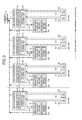
- FIG. 1 is a diagram illustrating a configuration of an in-train transmission control system according to a first embodiment.
- FIG. 2 is a diagram illustrating flows of command data in the configuration of FIG. 1 in the first embodiment.
- FIG. 3 is a diagram illustrating flows of device data and aggregated device data in the configuration of FIG. 1 in the first embodiment.
- FIG. 4 is a diagram illustrating a configuration of a comparative example of the in-train transmission control system in the first embodiment.
- FIG. 5 is a diagram illustrating flows of command data in the configuration of FIG. 4 in the first embodiment.
- FIG. 6 is a diagram illustrating flows of device data and aggregated device data in the configuration of FIG. 4 in the first embodiment.
- FIG. 7 is a diagram illustrating a configuration of an in-train transmission control system according to a second embodiment.
- FIG. 8 is a diagram illustrating a configuration of an in-train transmission control system according to a third embodiment.
- FIG. 1 is a diagram illustrating the configuration of an in-train transmission control system according to a first embodiment of the present invention.
- a central unit 10 which is provided in any car of a train formation composed of one or more cars and controls an operation of the entire train formation, transmits command data to devices 13 a , 13 b , 23 a , 23 b , 33 a , 33 b , 43 a , and 43 b provided in some or all of the cars, and the devices 13 a , 13 b , 23 a , 23 b , 33 a , 33 b , 43 a , and 43 b transmit device data to the central unit 10 .
- the system includes: line concentrators 11 , 21 , 31 , and 41 provided in the cars, respectively, each of which allows the command data from the central unit 10 to pass therethrough, and when receiving the device data from the device 13 a , 13 b , 23 a , 23 b , 33 a , 33 b , 43 a , or 43 b , transmits the device data to a relay device associated therewith; and relay devices 12 , 22 , 32 , and 42 provided in the cars, respectively, which aggregate the device data received from the line concentrators 11 , 21 , 31 , and 41 and transmit the device data to the central unit 10 .
- the first car includes the line concentrator 11 , the relay device 12 , and the devices 13 a and 13 b
- the second car includes the line concentrator 21 , the relay device 22 , and the devices 23 a and 23 b
- the third car includes the line concentrator 31 , the relay device 32 , and the devices 33 a and 33 b
- the fourth car includes the line concentrator 41 , the relay device 42 , and the devices 43 a and 43 b.
- the central unit 10 and the line concentrator 11 are connected by a transmission line 1
- the line concentrator 11 and the line concentrator 21 are connected by a transmission line 2
- the line concentrator 21 and the line concentrator 31 are connected by a transmission line 3
- the line concentrator 31 and the line concentrator 41 are connected by a transmission line 4 .
- the line concentrator 11 is connected with the relay device 12 by a transmission line 1 c , connected with the device 13 a by a transmission line 1 a , and connected with the device 13 b by a transmission line 1 b .
- the line concentrator 21 is connected with the relay device 22 by a transmission line 2 c , connected with the device 23 a by a transmission line 2 a , and connected with the device 23 b by a transmission line 2 b .
- the line concentrator 31 is connected with the relay device 32 by a transmission line 3 c , connected with the device 33 a by a transmission line 3 a , and connected with the device 33 b by a transmission line 3 b .
- the line concentrator 41 is connected with the relay device 42 by a transmission line 4 c , connected with the device 43 a by a transmission line 4 a , and connected with the device 43 b by a transmission line 4 b.
- the line concentrator 11 includes a received packet transmitting unit 11 A and a transmit data filtering unit 11 B.
- the relay device 12 includes a device data aggregating unit 12 A and a device data transmitting unit 12 B.
- the line concentrator 21 includes a received packet transmitting unit 21 A and a transmit data filtering unit 21 B.
- the relay device 22 includes a device data aggregating unit 22 A and a device data transmitting unit 22 B.
- the line concentrator 31 includes a received packet transmitting unit 31 A and a transmit data filtering unit 31 B.
- the relay device 32 includes a device data aggregating unit 32 A and a device data transmitting unit 32 B.
- the line concentrator 41 includes a received packet transmitting unit 41 A and a transmit data filtering unit 41 B.
- the relay device 42 includes a device data aggregating unit 42 A and a device data transmitting unit 42 B.
- the received packet transmitting units 11 A, 21 A, 31 A, and 41 A receive packets transmitted by the devices 13 a , 13 b , 23 a , 23 b , 33 a , 33 b , 43 a , and 43 b.
- the transmit data filtering units 11 B, 21 B, 31 B, and 41 B perform filtering of transmit data.
- command data and device data are transmitted using unicast addresses.
- Ethernet registered trademark
- UDP/IP User Datagram Protocol/Internet Protocol
- device data is transmitted in unicast addressing and controlled to head for a relay device based on a destination MAC address, a destination IP, a destination UDP port number, a transmission source MAC address, a transmission source IP, a transmission source UDP port number, or a VLAN tag of packets including the device data.
- the device data aggregating unit 12 A, 22 A, 32 A, and 42 A each concatenate received device data pieces and add information including a header to it to aggregate the result into a packet or packets.
- an applicable method of concatenating data there can be cited a method of concatenating device data in a predetermined order and a method of concatenating information indicating a data order and device data concatenated in this data order.
- the device data transmitting unit 12 B, 22 B, 32 B, and 42 B transmit device data aggregated by the device data aggregating unit 12 A, 22 A, 32 A, and 42 A, respectively.
- This data is anew received by the received packet transmitting unit 11 A, 21 A, 31 A, and 41 A of the line concentrators 11 , 21 , 31 , and 41 , and goes through the transmit data filtering units 11 B, 21 B, 31 B, and 41 B, and is transmitted to the central unit 10 .
- a device to be connected to a train information management system can be used. That is, a brake device, an inverter represented by a VVVF (Variable Voltage Variable Frequency) inverter and an SIV (Static InVerter), a safety device, and a master controller can be cited as examples.
- VVVF Very Voltage Variable Frequency
- SIV Static InVerter
- FIG. 2 is a diagram illustrating the flows of command data in the configuration of FIG. 1 .
- Command data is data to be transmitted from the central unit 10 to the device 13 a , 13 b , 23 a , 23 b , 33 a , 33 b , 43 a , and 43 b .
- a brake command can be used as the command data, for example.
- the command data is lower in occurrence frequency than the device data and smaller in data amount, but the urgency and degree of importance thereof for train operation is higher.
- Command data is often a common command common to the devices, and the number of packets thereof is invariable.
- the command data passes through the line concentrators 11 , 21 , 31 , and 41 as described above, the command data is received by the devices 13 a , 13 b , 23 a , 23 b , 33 a , 33 b , 43 a , and 43 b without delay.
- FIG. 3 is a diagram illustrating the flows of device data and aggregated device data in the configuration of FIG. 1 .
- the device data is data to be transmitted from the devices 13 a , 13 b , 23 a , 23 b , 33 a , 33 b , 43 a , and 43 b to the central unit 10 .
- the device data can be exemplified by temperature setting information of each car and door open/closed information of each car.
- the device data is lower in urgency and degree of importance for a train operation than the command data, but is higher in occurrence frequency and larger in data amount because the device data is transmitted from each device every constant period.
- the device data is transmitted from the line concentrator 11 , 21 , 31 , and 41 to the relay device 12 , 22 , 32 , and 42 , and aggregated by the relay device 12 , 22 , 32 , and 42 and transmitted to the central unit 10 via the line concentrator 11 , 21 , 31 , and 41 .
- a path of the command data is different from a path of the device data and the aggregated device data.
- the command data passes through the line concentrator, whereas the device data is handed over from the line concentrator to the relay device, and aggregated in the relay device and then transmitted to the central unit.
- data small in data amount but high in urgency and degree of importance, such as the brake command can be caused to reach the device without delay, and other data large in data amount but low in urgency and degree of importance such as the device data is aggregated, although the other data is delayed more than the command data. Therefore, it is possible to reduce data congestion in the transmission paths between the line concentrators and the transmission paths between the central unit and the line concentrators.
- the relay device aggregates the device data, it is possible to reduce not only data congestion in the transmission paths between the line concentrators and the transmission paths between the central unit and the line concentrators, but also a load for reception operation of the central unit. Yet further, aggregation by the relay devices can reduce the number of packets of the device data. Accordingly, the number of interrupts to the central unit is reduced, so that the efficiency of the central processing unit in the central unit can be improved. Note that, since the central unit outputs data high in urgency and degree of importance, represented by the brake command as exemplified above, improving the efficiency of the central processing unit in the central unit is just as very important as minimizing delay of the command data.
- FIG. 4 is a diagram illustrating the configuration of a comparative example of the in-train transmission control system.
- An in-train transmission control system illustrated in FIG. 4 includes: a central unit 50 controlling the operation of the entire in-train transmission control system; devices 64 a , 64 b , 74 a , 74 b , 84 a , 84 b , 94 a , and 94 b respectively provided in cars, line concentrators 61 , 71 , 81 , and 91 provided respectively in the cars, which when receiving command data, transmit the command data to relay devices 62 , 72 , 82 , and 92 , but when receiving aggregated device data, transmit the aggregated device data to the central unit 50 ; the relay devices 62 , 72 , 82 , and 92 provided respectively in the cars, which when receiving device data, aggregate the device data and transmit it to the central unit 50 , but when receiving command data, transmit the command data to line concentrators 63 , 73 , 83
- the central unit 50 and the line concentrator 61 are connected by a transmission line 6
- the line concentrator 61 and the line concentrator 71 are connected by a transmission line 7
- the line concentrator 71 and the line concentrator 81 are connected by a transmission line 8
- the line concentrator 81 and the line concentrator 91 are connected by a transmission line 9 , whereby a backbone network is formed.
- the relay device 62 is connected to the line concentrator 61 by a transmission line 6 a
- the line concentrator 63 is connected to the relay device 62 by a transmission line 6 b
- the line concentrator 63 is connected with the device 64 a by a transmission line 6 c and connected with the device 64 b by a transmission line 6 d , whereby a branch network of the first car is formed.
- the relay device 72 is connected to the line concentrator 71 by a transmission line 7 a
- the line concentrator 73 is connected to the relay device 72 by a transmission line 7 b .
- the line concentrator 73 is connected with the device 74 a by a transmission line 7 c and connected with the device 74 b by a transmission line 7 d , whereby a branch network of the second car is formed.
- the relay device 82 is connected to the line concentrator 81 by a transmission line 8 a
- the line concentrator 83 is connected to the relay device 82 by a transmission line 8 b .
- the line concentrator 83 is connected with the device 84 a by a transmission line 8 c and connected with the device 84 b by a transmission line 8 d , whereby a branch network of the third car is formed.
- the relay device 92 is connected to the line concentrator 91 by a transmission line 9 a
- the line concentrator 93 is connected to the relay device 92 by a transmission line 9 b
- the line concentrator 93 is connected with the device 94 a by a transmission line 9 c and connected with the device 94 b by a transmission line 9 d , whereby a branch network of the fourth car is formed.
- FIG. 5 is a diagram illustrating the flows of command data in the configuration of FIG. 4 .
- the command data is data to be transmitted from the central unit 50 to the device 64 a , 64 b , 74 a , 74 b , 84 a , 84 b , 94 a , or 94 b .
- the command data is received by the line concentrators 61 , 71 , 81 , and 91 and transmitted to the relay devices 62 , 72 , 82 , and 92 , and then received from the relay devices 62 , 72 , 82 , and 92 by the line concentrators 63 , 73 , 83 , and 93 .
- FIG. 6 is a diagram illustrating the flows of device data and aggregated device data in the configuration of FIG. 4 .
- the device data is data to be transmitted from the device 64 a , 64 b , 74 a , 74 b , 84 a , 84 b , 94 a , and 94 b to the central unit 50 .
- the device data is transmitted from the line concentrator 63 , 73 , 83 , or 93 to the relay device 62 , 72 , 82 , or 92 , and aggregated in the relay device 62 , 72 , 82 , or 92 to be transmitted to the line concentrator 61 , 71 , 81 , or 91 and then is transmitted to the central unit 50 via the line concentrator 61 , 71 , 81 , or 91 .
- a path for the command data is equal to a path for the device data and the aggregated device data.
- the device data is aggregated in the relay device as with the configuration of FIG. 1 , data congestion in the transmission paths between the line concentrators and the transmission paths between the central unit and the line concentrators can be reduced, but because the command data goes through two line concentrators and one relay device, the number of interfaces the command data is routed through is large, so that the command data suffers a rather long delay caused before reaching the device as compared with the configuration of FIG. 1 .
- the relay device makes a separation between the backbone network and the branch network, and so the relay device needs two network interfaces.
- a LAN port can be used for the network interface, for example.
- the command data passes through the line concentrator, whereas the device data is handed over from the line concentrator to the relay device, and aggregated in the relay device and then transmitted to the central unit, so that, while the delay of the command data is prevented, the device data can be aggregated and transmitted. Therefore, both minimizing the delay of the command data and reducing data congestion can be achieved.
- the number of cars of a train formation in the present invention is not limited to any number.
- the number of cars increases, the number of devices increases, and as the number of devices increases, the device data increases in data amount, so that data aggregation in the relay device becomes more important.
- the larger the number of cars the more conspicuous an advantageous effect obtained by applying the present invention is.
- the larger the number of devices the more conspicuous the effect obtained by applying the present invention is.
- each line concentrator functions as an access point of radio communication.
- the present invention is not limited to the in-train transmission control system described in the first embodiment, but includes the relay device in the first embodiment. That is, the present invention also covers the relay device provided in each car of a train formation composed of one or more cars, which does not receive command data transmitted from the central unit that controls the operation of the entire train formation, but receives device data transmitted from a device provided in each car and aggregate the received device data to transmit the aggregated device data to the central unit.
- FIG. 7 is a diagram illustrating the configuration of an in-train transmission control system according to a second embodiment of the present invention.
- the in-train transmission control system illustrated in FIG. 7 includes: a central unit 110 controlling the operation of the entire in-train transmission control system; devices 113 a , 113 b , 123 a , 123 b , 133 a , 133 b , 143 a , and 143 b respectively provided in the cars; line concentrators 111 , 121 , 131 , and 141 provided respectively in the cars, which allow command data from the central unit 110 to pass therethrough, and when receiving device data from the device 113 a , 113 b , 123 a , 123 b , 133 a , 133 b , 143 a , and 143 b , transmit the device data to their respective relay devices; and relay devices 112 , 122 , 132 , and 142 provided respectively in the cars, which aggregate the device data received
- the central unit 110 and the line concentrator 111 are connected by a transmission line 101
- the line concentrator 111 and the line concentrator 121 are connected by a transmission line 102
- the line concentrator 121 and the line concentrator 131 are connected by a transmission line 103
- the line concentrator 131 and the line concentrator 141 are connected by a transmission line 104 .
- the line concentrator 111 is connected with the relay device 112 by a transmission line 101 c , connected with the device 113 a by a transmission line 101 a , and connected with the device 113 b by a transmission line 101 b .
- the line concentrator 121 is connected with the relay device 122 by a transmission line 102 c , connected with the device 123 a by a transmission line 102 a , and connected with the device 123 b by a transmission line 102 b .
- the line concentrator 131 is connected with the relay device 132 by a transmission line 103 c , connected with the device 133 a by a transmission line 103 a , and connected with the device 133 b by a transmission line 103 b .
- the line concentrator 141 is connected with the relay device 142 by a transmission line 104 c , connected with the device 143 a by a transmission line 104 a , and connected with the device 143 b by a transmission line
- the line concentrator 111 includes a received packet transmitting unit 111 A and a transmit data filtering unit 111 B.
- the relay device 112 includes a device data aggregating unit 112 A and a device data transmitting unit 112 B.
- the line concentrator 121 includes a received packet transmitting unit 121 A and a transmit data filtering unit 121 B.
- the relay device 122 includes a device data aggregating unit 122 A and a device data transmitting unit 122 B.
- the line concentrator 131 includes a received packet transmitting unit 131 A and a transmit data filtering unit 131 B.
- the relay device 132 includes a device data aggregating unit 132 A and a device data transmitting unit 132 B.
- the line concentrator 141 includes a received packet transmitting unit 141 A and a transmit data filtering unit 141 B.
- the relay device 142 includes a device data aggregating unit 142 A and a device data transmitting unit 142 B.
- the command data and the device data are transmitted using a multicast address.
- the transmit data filtering units 111 B, 121 B, 131 B, and 141 B for example, when Ethernet (registered trademark) or UDP/IP (User Datagram Protocol/Internet Protocol) is adopted as a data transmission scheme for the device data, it is identified whether a packet is command data or device data, and it is determined whether or not to filter the packet, using the destination MAC address, destination IP, destination UDP port number, transmission source MAC address, transmission source IP, transmission source UDP port number, or VLAN tag of the packet including the command data and the device data.
- the received packet is a packet of the command data
- the packet is allowed to pass through without filtering the packet, and when the received packet is the device data, the device data is controlled not to be transmitted to a port between cars.
- the relay device does not need to add a destination again to the address of packets including the device data.
- FIG. 8 is a diagram illustrating the configuration of an in-train transmission control system according to a third embodiment of the present invention.
- the in-train transmission control system illustrated in FIG. 8 includes: central units 210 and 220 controlling an operation of the entire in-train transmission control system; devices 213 a , 213 b , 223 a , 223 b , 233 a , 233 b , 243 a , and 243 b respectively provided in the cars; line concentrators 211 , 221 , 231 , 241 , 215 , 225 , 235 , and 245 provided respectively in the cars, each of which allows command data from the central unit 210 and 220 to pass therethrough, and when receiving device data from the device 213 a , 213 b , 223 a , 223 b , 233 a , 233 b , 243 a , or 243 b , transmits the device data to a corresponding relay device; and relay devices
- the central unit 210 that is a first central unit and the line concentrator 211 are connected by a transmission line 201 , the line concentrator 211 and the line concentrator 221 are connected by a transmission line 202 , the line concentrator 221 and the line concentrator 231 are connected by a transmission line 203 , and the line concentrator 231 and the line concentrator 241 are connected by a transmission line 204 .
- the central unit 220 that is a second central unit and the line concentrator 215 are connected by a transmission line 205
- the line concentrator 215 and the line concentrator 225 are connected by a transmission line 206
- the line concentrator 225 and the line concentrator 235 are connected by a transmission line 207
- the line concentrator 235 and the line concentrator 245 are connected by a transmission line 208 .
- the central unit 210 and the line concentrator 215 are connected by a transmission line 209
- the central unit 220 and the line concentrator 211 are connected by a transmission line 219 .
- the line concentrator 211 is connected with the relay device 212 that is a first relay device by a transmission line 201 c , connected with the device 213 a by a transmission line 201 a , connected with the device 213 b by a transmission line 201 b , and connected with the relay device 214 that is a second relay device by a transmission line 201 d .
- the line concentrator 221 is connected with the relay device 222 that is a first relay device by a transmission line 202 c , connected with the device 223 a by a transmission line 202 a , connected with the device 223 b by a transmission line 202 b , and connected with the relay device 224 that is a second relay device by a transmission line 202 d .
- the line concentrator 231 is connected with the relay device 232 that is a first relay device by a transmission line 203 c , connected with the device 233 a by a transmission line 203 a , connected with the device 233 b by a transmission line 203 b , and connected with the relay device 234 that is a second relay device by a transmission line 203 d .
- the line concentrator 241 is connected with the relay device 242 that is a first relay device by a transmission line 204 c , connected with the device 243 a by a transmission line 204 a , connected with the device 243 b by a transmission line 204 b , and connected with the relay device 244 that is a second relay device by a transmission line 204 d .
- the line concentrator 215 is connected with the relay device 212 that is a first relay device by a transmission line 201 e , connected with the device 213 b by a transmission line 201 f , connected with the device 213 a by a transmission line 201 g , and connected with the relay device 214 that is a second relay device by a transmission line 201 h .
- the line concentrator 225 is connected with the relay device 222 that is a first relay device by a transmission line 202 e , connected with the device 223 b by a transmission line 202 f , connected with the device 223 a by a transmission line 202 g , and connected with the relay device 224 that is a second relay device by a transmission line 202 h .
- the line concentrator 235 is connected with the relay device 232 that is a first relay device by a transmission line 203 e , connected with the device 233 b by a transmission line 203 f , connected with the device 233 a by a transmission line 203 g , and connected with the relay device 234 that is a second relay device by a transmission line 203 h .
- the line concentrator 245 is connected with the relay device 242 that is a first relay device by a transmission line 204 e , connected with the device 243 b by a transmission line 204 f , connected with the device 243 a by a transmission line 204 g , and connected with the relay device 244 that is a second relay device by a transmission line 204 h.
- the line concentrator 211 includes a received packet transmitting unit 211 A and a transmit data filtering unit 211 B.
- the relay device 212 includes a device data aggregating unit 212 A and a device data transmitting unit 212 B.
- the line concentrator 221 includes a received packet transmitting unit 221 A and a transmit data filtering unit 221 B.
- the relay device 222 includes a device data aggregating unit 222 A and a device data transmitting unit 222 B.
- the line concentrator 231 includes a received packet transmitting unit 231 A and a transmit data filtering unit 2318 .
- the relay device 232 includes a device data aggregating unit 232 A and a device data transmitting unit 2328 .
- the line concentrator 241 includes a received packet transmitting unit 241 A and a transmit data filtering unit 2418 .
- the relay device 242 includes a device data aggregating unit 242 A and a device data transmitting unit 2428 .
- the relay device 214 includes a device data aggregating unit 214 A and a device data transmitting unit 214 B.
- the line concentrator 215 includes a received packet transmitting unit 215 A and a transmit data filtering unit 215 B.
- the relay device 224 includes a device data aggregating unit 224 A and a device data transmitting unit 224 B.
- the line concentrator 225 includes a received packet transmitting unit 2251 and a transmit data filtering unit 2252 .
- the relay device 234 includes a device data aggregating unit 234 A and a device data transmitting unit 234 B.
- the line concentrator 235 includes a received packet transmitting unit 235 A and a transmit data filtering unit 235 B.
- the relay device 244 includes a device data aggregating unit 244 A and a device data transmitting unit 244 B.
- the line concentrator 245 includes a received packet transmitting unit 2451 and a transmit data filtering unit 2452 .
- the central units, relay devices, and transmission paths are configured to be duplex, device data from the devices 213 a and 213 b in the first car, for example, can be transmitted to both the relay devices 212 and 214 by transmitting packets in multicast addressing. In this way, while the reliability of the in-train transmission control system is improved, the load on the central unit and the transmission load can be dispersed.
Landscapes
- Engineering & Computer Science (AREA)
- Mechanical Engineering (AREA)
- Power Engineering (AREA)
- Transportation (AREA)
- Computer Networks & Wireless Communication (AREA)
- Signal Processing (AREA)
- Electric Propulsion And Braking For Vehicles (AREA)
- Small-Scale Networks (AREA)
Abstract
Description
Claims (7)
Applications Claiming Priority (1)
| Application Number | Priority Date | Filing Date | Title |
|---|---|---|---|
| PCT/JP2015/063822 WO2016181536A1 (en) | 2015-05-13 | 2015-05-13 | On-train transmission control system and relay device |
Publications (2)
| Publication Number | Publication Date |
|---|---|
| US20180105066A1 US20180105066A1 (en) | 2018-04-19 |
| US10479217B2 true US10479217B2 (en) | 2019-11-19 |
Family
ID=57248950
Family Applications (1)
| Application Number | Title | Priority Date | Filing Date |
|---|---|---|---|
| US15/568,823 Active US10479217B2 (en) | 2015-05-13 | 2015-05-13 | In-train transmission control system and relay device |
Country Status (5)
| Country | Link |
|---|---|
| US (1) | US10479217B2 (en) |
| EP (1) | EP3296149B1 (en) |
| JP (1) | JP6391817B2 (en) |
| CN (1) | CN107531163B (en) |
| WO (1) | WO2016181536A1 (en) |
Families Citing this family (2)
| Publication number | Priority date | Publication date | Assignee | Title |
|---|---|---|---|---|
| FR3093604B1 (en) * | 2019-03-04 | 2021-04-02 | Faiveley Transp Tours | Data collection module relating to the equipment of a passenger transport vehicle. |
| CN111988293B (en) * | 2020-08-10 | 2021-10-15 | 广州通达汽车电气股份有限公司 | Method, device, equipment and storage medium for filtering domain name of vehicle-mounted router |
Citations (24)
| Publication number | Priority date | Publication date | Assignee | Title |
|---|---|---|---|---|
| US4582280A (en) * | 1983-09-14 | 1986-04-15 | Harris Corporation | Railroad communication system |
| JP2001275211A (en) | 2000-03-24 | 2001-10-05 | Toshiba Corp | Electric vehicle information system |
| US20030084395A1 (en) * | 2001-10-17 | 2003-05-01 | Bryant Robert Francis | Signal error detection in railroad communication system |
| US20070233364A1 (en) * | 2006-03-20 | 2007-10-04 | Ajith Kuttannair Kumar | Trip Optimization System and Method for a Vehicle |
| US20070241237A1 (en) * | 2006-04-17 | 2007-10-18 | Robert James Foy | Method, System, and Computer Software Code for Automated Establishment of a Distributed Power Train |
| US20090198391A1 (en) * | 2008-02-05 | 2009-08-06 | Ajith Kuttannair Kumar | System, method and computer software code for obtaining information for routing a powered system and adjusting a route in accordance with relevant information |
| US20090234521A1 (en) * | 2008-03-11 | 2009-09-17 | Ajith Kuttannair Kumar | System and Method For Managing An Amount of Stored Energy in a Powered System |
| US20090292411A1 (en) * | 2008-05-26 | 2009-11-26 | Smith Eugene A | System, method, and computer software code for linking a plurality of powered systems having different linking protocols to operate as a single powered system |
| US20100020723A1 (en) * | 2007-12-06 | 2010-01-28 | Mitsubishi Electric Corporation | Train car-to-car communication device |
| EP2221209A1 (en) | 2007-12-13 | 2010-08-25 | Mitsubishi Electric Corporation | Train communication system, communication device, and relay device |
| US20100262321A1 (en) * | 2006-03-20 | 2010-10-14 | Wolfgang Daum | System, Method and Computer Software Code for Optimizing Train Operations Considering Rail Car Parameters |
| US20110093144A1 (en) | 2009-03-17 | 2011-04-21 | Todd Goodermuth | System and method for communicating data in a train having one or more locomotive consists |
| JP2012105164A (en) | 2010-11-12 | 2012-05-31 | Hitachi Ltd | Information transmission system and train transmission system |
| US20120143407A1 (en) * | 2010-12-04 | 2012-06-07 | Murthy Srinand Sridhara | Method and system for rail vehicle control |
| US20120296501A1 (en) * | 2010-01-21 | 2012-11-22 | Mitsubishi Electric Corporation | Brake control device and brake control method |
| US20120318931A1 (en) * | 2006-04-17 | 2012-12-20 | Jared Klineman Cooper | System and method for automated establishment of a vehicle consist |
| US20140129061A1 (en) | 2009-03-17 | 2014-05-08 | General Electric Company | Data communication system and method |
| US20140379180A1 (en) * | 2013-06-19 | 2014-12-25 | Progress Rail Services Corporation | Power sharing for a locomotive consist |
| US20150013312A1 (en) * | 2011-08-19 | 2015-01-15 | General Electric Company | Method and system for regeneration in a vehicle in a consist |
| US20150057847A1 (en) * | 2013-08-23 | 2015-02-26 | Electro-Motive Diesel, Inc. | Trainline communication network access point including filter |
| US20150148013A1 (en) * | 2013-11-27 | 2015-05-28 | At&T Intellectual Property I, L.P. | Direct interaction between a user and a communication network |
| US20150343906A1 (en) * | 2013-02-22 | 2015-12-03 | Keita Hatanaka | Propulsion control apparatus for railroad vehicle |
| US20150360700A1 (en) * | 2006-04-17 | 2015-12-17 | General Electric Company | System and method for automated establishment of a vehicle consist |
| US20170090473A1 (en) * | 2006-04-17 | 2017-03-30 | General Electric Company | Vehicle communication system |
Family Cites Families (9)
| Publication number | Priority date | Publication date | Assignee | Title |
|---|---|---|---|---|
| JP3808824B2 (en) * | 2002-11-20 | 2006-08-16 | 株式会社日立製作所 | Information transmission system and information transmission method |
| JP4922120B2 (en) * | 2007-10-05 | 2012-04-25 | 株式会社オートネットワーク技術研究所 | Communication system and relay device |
| CN101980885B (en) * | 2008-04-07 | 2013-04-24 | 三菱电机株式会社 | Communication relay device for train, and communication relay method for train |
| JP5296515B2 (en) * | 2008-12-17 | 2013-09-25 | 株式会社東海理化電機製作所 | Vehicle communication system |
| DE102010010074A1 (en) * | 2010-02-25 | 2011-08-25 | Siemens Aktiengesellschaft, 80333 | Tracked vehicle |
| JP5677244B2 (en) * | 2011-09-08 | 2015-02-25 | 三菱電機株式会社 | Train information management device |
| JP5701197B2 (en) * | 2011-11-02 | 2015-04-15 | 三菱電機株式会社 | Train information management apparatus and train information management method |
| WO2014141361A1 (en) * | 2013-03-11 | 2014-09-18 | 三菱電機株式会社 | Train information management device |
| JP5795135B2 (en) * | 2013-05-20 | 2015-10-14 | 三菱電機株式会社 | Train information management device |
-
2015
- 2015-05-13 US US15/568,823 patent/US10479217B2/en active Active
- 2015-05-13 CN CN201580079580.0A patent/CN107531163B/en not_active Expired - Fee Related
- 2015-05-13 WO PCT/JP2015/063822 patent/WO2016181536A1/en not_active Ceased
- 2015-05-13 EP EP15891860.7A patent/EP3296149B1/en active Active
- 2015-05-13 JP JP2017517550A patent/JP6391817B2/en active Active
Patent Citations (24)
| Publication number | Priority date | Publication date | Assignee | Title |
|---|---|---|---|---|
| US4582280A (en) * | 1983-09-14 | 1986-04-15 | Harris Corporation | Railroad communication system |
| JP2001275211A (en) | 2000-03-24 | 2001-10-05 | Toshiba Corp | Electric vehicle information system |
| US20030084395A1 (en) * | 2001-10-17 | 2003-05-01 | Bryant Robert Francis | Signal error detection in railroad communication system |
| US20100262321A1 (en) * | 2006-03-20 | 2010-10-14 | Wolfgang Daum | System, Method and Computer Software Code for Optimizing Train Operations Considering Rail Car Parameters |
| US20070233364A1 (en) * | 2006-03-20 | 2007-10-04 | Ajith Kuttannair Kumar | Trip Optimization System and Method for a Vehicle |
| US20070241237A1 (en) * | 2006-04-17 | 2007-10-18 | Robert James Foy | Method, System, and Computer Software Code for Automated Establishment of a Distributed Power Train |
| US20150360700A1 (en) * | 2006-04-17 | 2015-12-17 | General Electric Company | System and method for automated establishment of a vehicle consist |
| US20170090473A1 (en) * | 2006-04-17 | 2017-03-30 | General Electric Company | Vehicle communication system |
| US20120318931A1 (en) * | 2006-04-17 | 2012-12-20 | Jared Klineman Cooper | System and method for automated establishment of a vehicle consist |
| US20100020723A1 (en) * | 2007-12-06 | 2010-01-28 | Mitsubishi Electric Corporation | Train car-to-car communication device |
| EP2221209A1 (en) | 2007-12-13 | 2010-08-25 | Mitsubishi Electric Corporation | Train communication system, communication device, and relay device |
| US20090198391A1 (en) * | 2008-02-05 | 2009-08-06 | Ajith Kuttannair Kumar | System, method and computer software code for obtaining information for routing a powered system and adjusting a route in accordance with relevant information |
| US20090234521A1 (en) * | 2008-03-11 | 2009-09-17 | Ajith Kuttannair Kumar | System and Method For Managing An Amount of Stored Energy in a Powered System |
| US20090292411A1 (en) * | 2008-05-26 | 2009-11-26 | Smith Eugene A | System, method, and computer software code for linking a plurality of powered systems having different linking protocols to operate as a single powered system |
| US20110093144A1 (en) | 2009-03-17 | 2011-04-21 | Todd Goodermuth | System and method for communicating data in a train having one or more locomotive consists |
| US20140129061A1 (en) | 2009-03-17 | 2014-05-08 | General Electric Company | Data communication system and method |
| US20120296501A1 (en) * | 2010-01-21 | 2012-11-22 | Mitsubishi Electric Corporation | Brake control device and brake control method |
| JP2012105164A (en) | 2010-11-12 | 2012-05-31 | Hitachi Ltd | Information transmission system and train transmission system |
| US20120143407A1 (en) * | 2010-12-04 | 2012-06-07 | Murthy Srinand Sridhara | Method and system for rail vehicle control |
| US20150013312A1 (en) * | 2011-08-19 | 2015-01-15 | General Electric Company | Method and system for regeneration in a vehicle in a consist |
| US20150343906A1 (en) * | 2013-02-22 | 2015-12-03 | Keita Hatanaka | Propulsion control apparatus for railroad vehicle |
| US20140379180A1 (en) * | 2013-06-19 | 2014-12-25 | Progress Rail Services Corporation | Power sharing for a locomotive consist |
| US20150057847A1 (en) * | 2013-08-23 | 2015-02-26 | Electro-Motive Diesel, Inc. | Trainline communication network access point including filter |
| US20150148013A1 (en) * | 2013-11-27 | 2015-05-28 | At&T Intellectual Property I, L.P. | Direct interaction between a user and a communication network |
Non-Patent Citations (4)
| Title |
|---|
| Extended European Search Report dated Apr. 25, 2018, issued by the European Patent Office in corresponding European Application No. 15891860.7. (8 pages). |
| International Search Report (PCT/ISA/210) dated Aug. 18, 2015, by the Japanese Patent Office as the International Searching Authority for International Application No. PCT/JP2015/063822. |
| Office Action dated Jul. 26, 2019, by the Chinese Patent Office in corresponding Chinese Patent Application No. 201580079580.0 and English translation of the Office Action. (18 pages). |
| Written Opinion (PCT/ISA/237) dated Aug. 18, 2015, by the Japanese Patent Office as the International Searching Authority for International Application No. PCT/JP2015/063822. |
Also Published As
| Publication number | Publication date |
|---|---|
| EP3296149A4 (en) | 2018-05-23 |
| US20180105066A1 (en) | 2018-04-19 |
| EP3296149A1 (en) | 2018-03-21 |
| WO2016181536A1 (en) | 2016-11-17 |
| JP6391817B2 (en) | 2018-09-19 |
| JPWO2016181536A1 (en) | 2017-10-12 |
| CN107531163B (en) | 2020-03-03 |
| CN107531163A (en) | 2018-01-02 |
| EP3296149B1 (en) | 2022-06-08 |
Similar Documents
| Publication | Publication Date | Title |
|---|---|---|
| US10924300B2 (en) | Virtual controller area network | |
| JP6506850B2 (en) | Vehicle gateway device | |
| US9451056B2 (en) | Method for mapping packets to network virtualization instances | |
| US10911355B2 (en) | Multi-site telemetry tracking for fabric traffic using in-band telemetry | |
| US9819574B2 (en) | Concerted multi-destination forwarding in a joint TRILL fabric and VXLAN/IP fabric data center | |
| US20200145293A1 (en) | Network monitor, network monitoring method, and recording medium storing program | |
| CN107005593B (en) | Method and control device for the transmission of safety-relevant data in a motor vehicle by means of the Ethernet standard | |
| JP2017005617A (en) | Relay device, electronic device, and communication system | |
| US20160036732A1 (en) | System and Method for Network Protocol Offloading in Virtual Networks | |
| US20220385497A1 (en) | Method for network slices to share uplink port, apparatus, and storage medium | |
| US10479217B2 (en) | In-train transmission control system and relay device | |
| US20160269322A1 (en) | Switch device, control method, and storage medium | |
| US9923733B2 (en) | Network system and communication apparatus for performing communication among networks having different VLAN settings | |
| JP2007174152A (en) | Network congestion control system and method thereof | |
| US10291517B1 (en) | Generating a dummy VLAN tag for indicating quality of service classification information in a distributed routing system | |
| JP5939916B2 (en) | Information transmission system | |
| EP2988457A1 (en) | Gateway device, network system including gateway device, air-conditioning outdoor unit, and air-conditioning network system | |
| EP2975776A1 (en) | Train information management device | |
| US9531567B2 (en) | Network system | |
| RU2735968C1 (en) | Method and device for transmitting data between first communication network of first rail transport unit and second communication network of second rail transport unit | |
| EP3253008B1 (en) | Transfer apparatus | |
| EP3038295B1 (en) | Method and device for communicating control information | |
| Nitta et al. | QoS Evaluation of In-Vehicle Network with SPQ of IEEE 802.1 TSN | |
| JP2025112496A (en) | communication equipment | |
| MY195472A (en) | System and Method of Single Point Channel Bonding and Network Convergence for Hybrid Access Gateways |
Legal Events
| Date | Code | Title | Description |
|---|---|---|---|
| AS | Assignment |
Owner name: MITSUBISHI ELECTRIC CORPORATION, JAPAN Free format text: ASSIGNMENT OF ASSIGNORS INTEREST;ASSIGNORS:TATSUMI, SHOGO;HONDA, SHINGO;HIRATA, TOMOYUKI;REEL/FRAME:043930/0139 Effective date: 20170925 |
|
| FEPP | Fee payment procedure |
Free format text: ENTITY STATUS SET TO UNDISCOUNTED (ORIGINAL EVENT CODE: BIG.); ENTITY STATUS OF PATENT OWNER: LARGE ENTITY |
|
| STPP | Information on status: patent application and granting procedure in general |
Free format text: RESPONSE TO NON-FINAL OFFICE ACTION ENTERED AND FORWARDED TO EXAMINER |
|
| STPP | Information on status: patent application and granting procedure in general |
Free format text: FINAL REJECTION MAILED |
|
| STPP | Information on status: patent application and granting procedure in general |
Free format text: RESPONSE AFTER FINAL ACTION FORWARDED TO EXAMINER |
|
| STPP | Information on status: patent application and granting procedure in general |
Free format text: NOTICE OF ALLOWANCE MAILED -- APPLICATION RECEIVED IN OFFICE OF PUBLICATIONS |
|
| STPP | Information on status: patent application and granting procedure in general |
Free format text: AWAITING TC RESP., ISSUE FEE NOT PAID |
|
| STCF | Information on status: patent grant |
Free format text: PATENTED CASE |
|
| MAFP | Maintenance fee payment |
Free format text: PAYMENT OF MAINTENANCE FEE, 4TH YEAR, LARGE ENTITY (ORIGINAL EVENT CODE: M1551); ENTITY STATUS OF PATENT OWNER: LARGE ENTITY Year of fee payment: 4 |