US10479021B2 - Curved plate production by additive layer manufacture - Google Patents

Curved plate production by additive layer manufacture Download PDF

Info

Publication number
US10479021B2
US10479021B2 US16/044,859 US201816044859A US10479021B2 US 10479021 B2 US10479021 B2 US 10479021B2 US 201816044859 A US201816044859 A US 201816044859A US 10479021 B2 US10479021 B2 US 10479021B2
Authority
US
United States
Prior art keywords
plate
layer
bottom edge
sacrificial
additions
Prior art date
Legal status (The legal status is an assumption and is not a legal conclusion. Google has not performed a legal analysis and makes no representation as to the accuracy of the status listed.)
Active
Application number
US16/044,859
Other versions
US20190030824A1 (en
Inventor
Matthew TAN
Current Assignee (The listed assignees may be inaccurate. Google has not performed a legal analysis and makes no representation or warranty as to the accuracy of the list.)
Rolls Royce PLC
Original Assignee
Rolls Royce PLC
Priority date (The priority date is an assumption and is not a legal conclusion. Google has not performed a legal analysis and makes no representation as to the accuracy of the date listed.)
Filing date
Publication date
Application filed by Rolls Royce PLC filed Critical Rolls Royce PLC
Publication of US20190030824A1 publication Critical patent/US20190030824A1/en
Assigned to ROLLS-ROYCE PLC reassignment ROLLS-ROYCE PLC ASSIGNMENT OF ASSIGNORS INTEREST (SEE DOCUMENT FOR DETAILS). Assignors: Tan, Matthew
Application granted granted Critical
Publication of US10479021B2 publication Critical patent/US10479021B2/en
Active legal-status Critical Current
Anticipated expiration legal-status Critical

Links

Images

Classifications

    • BPERFORMING OPERATIONS; TRANSPORTING
    • B29WORKING OF PLASTICS; WORKING OF SUBSTANCES IN A PLASTIC STATE IN GENERAL
    • B29CSHAPING OR JOINING OF PLASTICS; SHAPING OF MATERIAL IN A PLASTIC STATE, NOT OTHERWISE PROVIDED FOR; AFTER-TREATMENT OF THE SHAPED PRODUCTS, e.g. REPAIRING
    • B29C64/00Additive manufacturing, i.e. manufacturing of three-dimensional [3D] objects by additive deposition, additive agglomeration or additive layering, e.g. by 3D printing, stereolithography or selective laser sintering
    • B29C64/40Structures for supporting 3D objects during manufacture and intended to be sacrificed after completion thereof
    • BPERFORMING OPERATIONS; TRANSPORTING
    • B22CASTING; POWDER METALLURGY
    • B22FWORKING METALLIC POWDER; MANUFACTURE OF ARTICLES FROM METALLIC POWDER; MAKING METALLIC POWDER; APPARATUS OR DEVICES SPECIALLY ADAPTED FOR METALLIC POWDER
    • B22F10/00Additive manufacturing of workpieces or articles from metallic powder
    • B22F10/20Direct sintering or melting
    • BPERFORMING OPERATIONS; TRANSPORTING
    • B22CASTING; POWDER METALLURGY
    • B22FWORKING METALLIC POWDER; MANUFACTURE OF ARTICLES FROM METALLIC POWDER; MAKING METALLIC POWDER; APPARATUS OR DEVICES SPECIALLY ADAPTED FOR METALLIC POWDER
    • B22F10/00Additive manufacturing of workpieces or articles from metallic powder
    • B22F10/40Structures for supporting workpieces or articles during manufacture and removed afterwards
    • B22F3/1055
    • BPERFORMING OPERATIONS; TRANSPORTING
    • B29WORKING OF PLASTICS; WORKING OF SUBSTANCES IN A PLASTIC STATE IN GENERAL
    • B29CSHAPING OR JOINING OF PLASTICS; SHAPING OF MATERIAL IN A PLASTIC STATE, NOT OTHERWISE PROVIDED FOR; AFTER-TREATMENT OF THE SHAPED PRODUCTS, e.g. REPAIRING
    • B29C64/00Additive manufacturing, i.e. manufacturing of three-dimensional [3D] objects by additive deposition, additive agglomeration or additive layering, e.g. by 3D printing, stereolithography or selective laser sintering
    • B29C64/10Processes of additive manufacturing
    • B29C64/141Processes of additive manufacturing using only solid materials
    • B29C64/153Processes of additive manufacturing using only solid materials using layers of powder being selectively joined, e.g. by selective laser sintering or melting
    • BPERFORMING OPERATIONS; TRANSPORTING
    • B33ADDITIVE MANUFACTURING TECHNOLOGY
    • B33YADDITIVE MANUFACTURING, i.e. MANUFACTURING OF THREE-DIMENSIONAL [3-D] OBJECTS BY ADDITIVE DEPOSITION, ADDITIVE AGGLOMERATION OR ADDITIVE LAYERING, e.g. BY 3-D PRINTING, STEREOLITHOGRAPHY OR SELECTIVE LASER SINTERING
    • B33Y10/00Processes of additive manufacturing
    • B22F2003/1058
    • BPERFORMING OPERATIONS; TRANSPORTING
    • B29WORKING OF PLASTICS; WORKING OF SUBSTANCES IN A PLASTIC STATE IN GENERAL
    • B29LINDEXING SCHEME ASSOCIATED WITH SUBCLASS B29C, RELATING TO PARTICULAR ARTICLES
    • B29L2007/00Flat articles, e.g. films or sheets
    • B29L2007/002Panels; Plates; Sheets
    • BPERFORMING OPERATIONS; TRANSPORTING
    • B29WORKING OF PLASTICS; WORKING OF SUBSTANCES IN A PLASTIC STATE IN GENERAL
    • B29LINDEXING SCHEME ASSOCIATED WITH SUBCLASS B29C, RELATING TO PARTICULAR ARTICLES
    • B29L2031/00Other particular articles
    • B29L2031/772Articles characterised by their shape and not otherwise provided for
    • B29L2031/7739Curved shaped
    • BPERFORMING OPERATIONS; TRANSPORTING
    • B33ADDITIVE MANUFACTURING TECHNOLOGY
    • B33YADDITIVE MANUFACTURING, i.e. MANUFACTURING OF THREE-DIMENSIONAL [3-D] OBJECTS BY ADDITIVE DEPOSITION, ADDITIVE AGGLOMERATION OR ADDITIVE LAYERING, e.g. BY 3-D PRINTING, STEREOLITHOGRAPHY OR SELECTIVE LASER SINTERING
    • B33Y80/00Products made by additive manufacturing
    • YGENERAL TAGGING OF NEW TECHNOLOGICAL DEVELOPMENTS; GENERAL TAGGING OF CROSS-SECTIONAL TECHNOLOGIES SPANNING OVER SEVERAL SECTIONS OF THE IPC; TECHNICAL SUBJECTS COVERED BY FORMER USPC CROSS-REFERENCE ART COLLECTIONS [XRACs] AND DIGESTS
    • Y02TECHNOLOGIES OR APPLICATIONS FOR MITIGATION OR ADAPTATION AGAINST CLIMATE CHANGE
    • Y02PCLIMATE CHANGE MITIGATION TECHNOLOGIES IN THE PRODUCTION OR PROCESSING OF GOODS
    • Y02P10/00Technologies related to metal processing
    • Y02P10/25Process efficiency

Definitions

  • the present disclosure relates to a method of producing a curved plate by additive layer manufacture.
  • Additive layer manufacturing is a technology that enables the fabrication of complex, near net shape components by deposition of many layers of one or more specific materials.
  • powder bed ALM constructs components layer by layer by depositing powder on a machine bed or base/build plate and then selectively consolidating or fusing the powder using an energy beam such as a laser or an electron beam. The powder deposition/consolidation steps are repeated to produce a three dimensional component.
  • a significant advantage of ALM is reducing the amount of material that needs to be purchased in order to manufacture a final part. This is particularly important for high value-added materials as typically used in the aerospace industry. Also ALM components can have performance and weight advantages over components manufactured by more traditional methods.
  • An ALM part may be in the form of a plate, and in particular a plate having double curvatures.
  • the resulting plate When built up from a bottom edge by ALM, the resulting plate inevitably arches over that bottom edge. A problem can then arise in that this arching may produce distortions along particularly the lateral edges of the plate which extend upwards from the ends of the bottom edge.
  • FIG. 1 shows a result of finite element modelling of a plate 100 produced by ALM by deposition of layers on a base 101 , the direction and locations of the principal distortions being indicated by arrows.
  • FIG. 2 shows a cross-sectional view at mid-height through the plate 100 of FIG. 1 on a plane normal to direction z.
  • the black arrows indicate the principal distortions
  • the grey features 102 indicate the possible locations of support structures to counter these distortions.
  • permanent distortion along the lateral edges may not be avoided. This can be a particular problem if the lateral edges are required to carry fine features.
  • the present disclosure provides a method of producing a curved plate by additive layer manufacture, the method including:
  • first and second lateral edges of the plate each grow layer-by-layer to extend between respective ends of the bottom and top edges, and the plate thus built up arches over from the bottom edge to adopt a curved shape on cross-sections through the plate normal to the bottom edge;
  • each sacrificial plate addition continuing the geometry of the plate beyond its lateral edge such that the additions also arch over from the bottom edge to adopt a curved shape on cross-sections through the additions normal to the bottom edge;
  • the method may have any one or, to the extent that they are compatible, any combination of the following optional features.
  • the sacrificial plate additions may be thinned where they join to the plate along the first and second lateral edges. In this way the subsequent removal of the additions may be facilitated.
  • the length of each sacrificial plate addition in the direction of the bottom edge may be at least 5% of the length of the bottom edge, and preferably at least 10% of the length of the bottom edge.
  • the length of each sacrificial plate addition can be set so as to ensure that the inflection points of a distortion are located at the junctions of the lateral edges and the sacrificial plate additions. Increasing the length of each sacrificial plate addition in this direction can move more distortion out of the finished plate. However, increasing the length by too much wastes material. Therefore, the length of each sacrificial plate addition in the direction of the bottom edge may be at most 30% of the length of the bottom edge, and preferably at most 20% of the length of the bottom edge.
  • the spacing between the first and second lateral edges and/or the spacing between the bottom and top edges may be at least 10 or 15 times greater than the thickness of the plate.
  • One or each of the sacrificial plate additions may be anchored during plate build up by further additive layer material to a respective support structure.
  • the plate thus built up typically also has a curved shape on cross-sections normal to the direction of additive layer growth, i.e. the plate typically has double curvatures.
  • the plate may only have a curved shape on cross-sections through the additions normal to the bottom edge, i.e. may have a single curvature.
  • FIG. 1 shows a result of finite element modelling of a plate produced by additive layer manufacturing (ALM);
  • FIG. 2 shows a cross-sectional view at mid-height through the plate of FIG. 1 on a plane normal to direction z;
  • FIG. 3 shows schematically a plate as built up from a base by ALM
  • FIG. 4 shows a result of finite element modelling of the plate of FIG. 4 ;
  • FIG. 5 shows a cross-sectional view at mid-height through a variant of the plate of FIG. 3 and FIG. 4 on a plane normal to direction z.
  • FIG. 3 shows schematically a plate 30 built up from a base 31 by ALM.
  • the plate 30 has a bottom edge 32 formed by the first ALM layer, and is additively extended upwards therefrom by subsequent layers to a top edge 33 formed by the last ALM layer.
  • the plate has a curved shape on cross-sections through the plate normal to the bottom edge and consequently arches over the bottom edge.
  • First and second lateral edges 34 of the plate extend between the bottom and top edges and join via thinned regions to respective sacrificial additions 35 which are built up by ALM simultaneously with the plate and continue the arched geometry of the plate beyond its lateral edges.
  • the spacings between the first and second lateral edges and between the bottom and top edges are at least ten times greater than the thickness of the plate.
  • the sacrificial material in the additions 35 behaves as an extension of the plate geometry so that distortions and plastic deformation which would otherwise occur along the lateral edges 34 are displaced to the additions, which are then removed after the ALM process, e.g. by machining.
  • FIG. 4 shows a result of finite element modelling of the plate 30 , the direction and locations of the principal distortions being indicated by arrows. Relative to the modelling result of FIG. 1 , the displacement of the edge distortions is evident. Such modelling can also be used to show that plastic strains are similarly displaced.
  • each sacrificial addition 35 in the direction of the bottom edge 32 can be in the range of from 5% to 30% of the length of the bottom edge.
  • the lower limit is generally enough to ensure that most distortions are displaced to the addition, and the upper limit can avoid excessive material wastage.
  • An advantage of this ALM method is that it is possible to avoid making contact onto critical surfaces of the plate 30 with stiffening supports.
  • FIG. 5 shows a cross-sectional view at mid-height through a variant of the plate 30 on a plane normal to direction z.
  • members 36 produced by ALM extend therefrom and locate against support structures 37 , which also make supporting contact with the plate 30 adjacent the lateral edges 34 .
  • the ALM method can advantageously be applied to the production of any ALM component with such an arched geometry.

Abstract

A method of producing a curved plate by additive layer manufacture is provided. The method includes building up the plate layer-by-layer such that a first layer forms a bottom edge of the plate and the plate is additively extended upwards therefrom by subsequent layers such that a last layer forms an opposing top edge of the plate. In this way, spaced, first and second lateral edges of the plate each grow layer-by-layer to extend between respective ends of the bottom and top edges. The plate thus built up arches over from the bottom edge to adopt a curved shape on cross-sections through the plate normal to the bottom edge.

Description

CROSS-REFERENCE TO RELATED APPLICATIONS
This application is based upon and claims the benefit of priority from British Patent Application No. GB 1712002.3, filed on 26 Jul. 2017, the entire contents of which are incorporated by reference.
BACKGROUND Technical Field
The present disclosure relates to a method of producing a curved plate by additive layer manufacture.
Description of the Related Art Additive layer manufacturing (ALM) is a technology that enables the fabrication of complex, near net shape components by deposition of many layers of one or more specific materials. For example, powder bed ALM constructs components layer by layer by depositing powder on a machine bed or base/build plate and then selectively consolidating or fusing the powder using an energy beam such as a laser or an electron beam. The powder deposition/consolidation steps are repeated to produce a three dimensional component.
A significant advantage of ALM is reducing the amount of material that needs to be purchased in order to manufacture a final part. This is particularly important for high value-added materials as typically used in the aerospace industry. Also ALM components can have performance and weight advantages over components manufactured by more traditional methods.
However, residual stress and distortion are significant problems when producing a part by ALM. Distortion of the part can cause fit-up problems during assembly, and reduce the dimensional accuracy of the final product. In addition the stresses can have a detrimental effect on the mechanical properties of the part.
An ALM part may be in the form of a plate, and in particular a plate having double curvatures. When built up from a bottom edge by ALM, the resulting plate inevitably arches over that bottom edge. A problem can then arise in that this arching may produce distortions along particularly the lateral edges of the plate which extend upwards from the ends of the bottom edge. FIG. 1 shows a result of finite element modelling of a plate 100 produced by ALM by deposition of layers on a base 101, the direction and locations of the principal distortions being indicated by arrows.
To limit this distortion, structures can be placed to increase stiffness in the direction parallel to the preferential mode of distortion. For example, FIG. 2 shows a cross-sectional view at mid-height through the plate 100 of FIG. 1 on a plane normal to direction z. The black arrows indicate the principal distortions, and the grey features 102 indicate the possible locations of support structures to counter these distortions. However, even using such structures, permanent distortion along the lateral edges may not be avoided. This can be a particular problem if the lateral edges are required to carry fine features.
SUMMARY
Accordingly, the present disclosure provides a method of producing a curved plate by additive layer manufacture, the method including:
building up the plate layer-by-layer such that a first layer forms a bottom edge of the plate and the plate is additively extended upwards therefrom by subsequent layers such that a last layer forms an opposing top edge of the plate, wherein spaced, first and second lateral edges of the plate each grow layer-by-layer to extend between respective ends of the bottom and top edges, and the plate thus built up arches over from the bottom edge to adopt a curved shape on cross-sections through the plate normal to the bottom edge;
simultaneously building up layer-by-layer with the plate first and second sacrificial plate additions along respectively the first and second lateral edges, each sacrificial plate addition continuing the geometry of the plate beyond its lateral edge such that the additions also arch over from the bottom edge to adopt a curved shape on cross-sections through the additions normal to the bottom edge; and
removing the sacrificial plate additions.
Advantageously, by adding sacrificial material in the form of the additions which continue the geometry of the plate rather than by providing supports or sacrificial material in the direction of distortion, it is possible to displace any distortions into the additions, where they are then removed from the final plate. In other words, instead of attempting to eliminate unwanted distortions, the method moves them to a safe place.
The method may have any one or, to the extent that they are compatible, any combination of the following optional features.
The sacrificial plate additions may be thinned where they join to the plate along the first and second lateral edges. In this way the subsequent removal of the additions may be facilitated.
The length of each sacrificial plate addition in the direction of the bottom edge may be at least 5% of the length of the bottom edge, and preferably at least 10% of the length of the bottom edge. In general, the length of each sacrificial plate addition can be set so as to ensure that the inflection points of a distortion are located at the junctions of the lateral edges and the sacrificial plate additions. Increasing the length of each sacrificial plate addition in this direction can move more distortion out of the finished plate. However, increasing the length by too much wastes material. Therefore, the length of each sacrificial plate addition in the direction of the bottom edge may be at most 30% of the length of the bottom edge, and preferably at most 20% of the length of the bottom edge.
The spacing between the first and second lateral edges and/or the spacing between the bottom and top edges may be at least 10 or 15 times greater than the thickness of the plate.
One or each of the sacrificial plate additions may be anchored during plate build up by further additive layer material to a respective support structure. Thus it is possible to combine the sacrificial approach and the support approach to reducing or eliminating distortions.
The plate thus built up typically also has a curved shape on cross-sections normal to the direction of additive layer growth, i.e. the plate typically has double curvatures. However, this does not exclude that the plate may only have a curved shape on cross-sections through the additions normal to the bottom edge, i.e. may have a single curvature.
DESCRIPTION OF THE DRAWINGS
Embodiments of the present disclosure will now be described by way of example with reference to the accompanying drawings in which:
FIG. 1 shows a result of finite element modelling of a plate produced by additive layer manufacturing (ALM);
FIG. 2 shows a cross-sectional view at mid-height through the plate of FIG. 1 on a plane normal to direction z;
FIG. 3 shows schematically a plate as built up from a base by ALM;
FIG. 4 shows a result of finite element modelling of the plate of FIG. 4; and
FIG. 5 shows a cross-sectional view at mid-height through a variant of the plate of FIG. 3 and FIG. 4 on a plane normal to direction z.
DETAILED DESCRIPTION
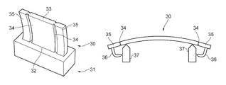
FIG. 3 shows schematically a plate 30 built up from a base 31 by ALM. The plate 30 has a bottom edge 32 formed by the first ALM layer, and is additively extended upwards therefrom by subsequent layers to a top edge 33 formed by the last ALM layer. The plate has a curved shape on cross-sections through the plate normal to the bottom edge and consequently arches over the bottom edge. First and second lateral edges 34 of the plate extend between the bottom and top edges and join via thinned regions to respective sacrificial additions 35 which are built up by ALM simultaneously with the plate and continue the arched geometry of the plate beyond its lateral edges. Typically, the spacings between the first and second lateral edges and between the bottom and top edges are at least ten times greater than the thickness of the plate.
The sacrificial material in the additions 35 behaves as an extension of the plate geometry so that distortions and plastic deformation which would otherwise occur along the lateral edges 34 are displaced to the additions, which are then removed after the ALM process, e.g. by machining.
For example, FIG. 4 shows a result of finite element modelling of the plate 30, the direction and locations of the principal distortions being indicated by arrows. Relative to the modelling result of FIG. 1, the displacement of the edge distortions is evident. Such modelling can also be used to show that plastic strains are similarly displaced.
The length of each sacrificial addition 35 in the direction of the bottom edge 32 can be in the range of from 5% to 30% of the length of the bottom edge. The lower limit is generally enough to ensure that most distortions are displaced to the addition, and the upper limit can avoid excessive material wastage.
An advantage of this ALM method is that it is possible to avoid making contact onto critical surfaces of the plate 30 with stiffening supports.
Moreover, relative to conventional approaches which attempt to combat distortions and plastic deformation by use of such stiffening supports, the ALM method can advantageously use lower volumes of sacrificial material and can better isolate of plastic deformations away from potentially sensitive locations (e.g. along the lateral edges 34). However, this does not exclude the adoption of a combined approach. Thus FIG. 5 shows a cross-sectional view at mid-height through a variant of the plate 30 on a plane normal to direction z. To supplement the sacrificial additions 35, members 36 produced by ALM extend therefrom and locate against support structures 37, which also make supporting contact with the plate 30 adjacent the lateral edges 34.
The ALM method can advantageously be applied to the production of any ALM component with such an arched geometry.
While the invention has been described in conjunction with the exemplary embodiments described above, many equivalent modifications and variations will be apparent to those skilled in the art when given this disclosure. Accordingly, the exemplary embodiments of the invention set forth above are considered to be illustrative and not limiting. Various changes to the described embodiments may be made without departing from the spirit and scope of the invention.

Claims (7)

The invention claimed is:
1. A method of producing a curved plate by additive layer manufacture, the method including:
building up the plate layer-by-layer such that a first layer forms a bottom edge of the plate and the plate is additively extended upwards therefrom by subsequent layers such that a last layer forms an opposing top edge of the plate, wherein spaced, first and second lateral edges of the plate each grow layer-by-layer to extend between respective ends of the bottom and top edges, and the plate thus built up arches over from the bottom edge to adopt a curved shape on cross-sections through the plate normal to the bottom edge;
simultaneously building up layer-by-layer with the plate first and second sacrificial plate additions along respectively the first and second lateral edges, each sacrificial plate addition continuing the geometry of the plate beyond its lateral edge such that the additions also arch over from the bottom edge to adopt a curved shape on cross-sections through the additions normal to the bottom edge; and
removing the sacrificial plate additions.
2. A method of producing a curved plate according to claim 1, wherein the sacrificial plate additions are thinned where they join to the plate along the first and second lateral edges.
3. A method of producing a curved plate according to claim 1, wherein the length of each sacrificial plate addition in the direction of the bottom edge is at least 5% of the length of the bottom edge.
4. A method of producing a curved plate according to claim 1, wherein the length of each sacrificial plate addition in the direction of the bottom edge is at most 30% of the length of the bottom edge.
5. A method of producing a curved plate according to claim 1, wherein the spacing between the first and second lateral edges and/or the spacing between the bottom and top edges is at least ten times greater than the thickness of the plate.
6. A method of producing a curved plate according to claim 1, wherein one or each of the sacrificial plate additions is anchored during plate build up by further additive layer material to a respective support structure.
7. A method of producing a curved plate according to claim 1, wherein the plate thus built up also has a curved shape on cross-sections normal to the direction of additive layer growth.
US16/044,859 2017-07-26 2018-07-25 Curved plate production by additive layer manufacture Active US10479021B2 (en)

Applications Claiming Priority (2)

Application Number Priority Date Filing Date Title
GBGB1712002.3A GB201712002D0 (en) 2017-07-26 2017-07-26 Curved plate production by additive layer manufacture
GB1712002.3 2017-07-26

Publications (2)

Publication Number Publication Date
US20190030824A1 US20190030824A1 (en) 2019-01-31
US10479021B2 true US10479021B2 (en) 2019-11-19

Family

ID=59771646

Family Applications (1)

Application Number Title Priority Date Filing Date
US16/044,859 Active US10479021B2 (en) 2017-07-26 2018-07-25 Curved plate production by additive layer manufacture

Country Status (3)

Country Link
US (1) US10479021B2 (en)
EP (1) EP3434452B1 (en)
GB (1) GB201712002D0 (en)

Families Citing this family (3)

* Cited by examiner, † Cited by third party
Publication number Priority date Publication date Assignee Title
GB202211677D0 (en) * 2022-08-10 2022-09-21 Rolls Royce Plc A method of manufacturing a component
GB202211722D0 (en) * 2022-08-11 2022-09-28 Rolls Royce Plc A method of manufacturing a component
US11819920B1 (en) * 2022-09-12 2023-11-21 Chromalloy Gas Turbine Llc Systems and methods for repairing compressor blades using hybrid manufacturing techniques

Citations (6)

* Cited by examiner, † Cited by third party
Publication number Priority date Publication date Assignee Title
US20160059315A1 (en) 2013-04-10 2016-03-03 Snecma Method for manufacturing an asymmetric component using additive manufacturing
US20160271699A1 (en) * 2015-03-18 2016-09-22 Materials Solutions Limited Additive manufacturing
US20160332259A1 (en) 2015-05-11 2016-11-17 Rolls-Royce Plc Additive layer manufacturing methods
US20170232518A1 (en) * 2014-08-11 2017-08-17 Soochow University Synchronous powder-feeding space laser machining and three-dimensional forming method and device
US20180111334A1 (en) * 2016-10-26 2018-04-26 General Electric Company Methods and thermal structures for additive manufacturing
US20180169954A1 (en) * 2016-12-20 2018-06-21 Textron Aviation Inc. Additive manufacturing method for improved core structure

Patent Citations (6)

* Cited by examiner, † Cited by third party
Publication number Priority date Publication date Assignee Title
US20160059315A1 (en) 2013-04-10 2016-03-03 Snecma Method for manufacturing an asymmetric component using additive manufacturing
US20170232518A1 (en) * 2014-08-11 2017-08-17 Soochow University Synchronous powder-feeding space laser machining and three-dimensional forming method and device
US20160271699A1 (en) * 2015-03-18 2016-09-22 Materials Solutions Limited Additive manufacturing
US20160332259A1 (en) 2015-05-11 2016-11-17 Rolls-Royce Plc Additive layer manufacturing methods
US20180111334A1 (en) * 2016-10-26 2018-04-26 General Electric Company Methods and thermal structures for additive manufacturing
US20180169954A1 (en) * 2016-12-20 2018-06-21 Textron Aviation Inc. Additive manufacturing method for improved core structure

Non-Patent Citations (1)

* Cited by examiner, † Cited by third party
Title
Great Britain Search Report dated Nov. 16, 2017, in GB Patent Application No. 1712002.3.

Also Published As

Publication number Publication date
US20190030824A1 (en) 2019-01-31
EP3434452A1 (en) 2019-01-30
EP3434452B1 (en) 2020-03-11
GB201712002D0 (en) 2017-09-06

Similar Documents

Publication Publication Date Title
US10479021B2 (en) Curved plate production by additive layer manufacture
KR102330987B1 (en) Method for the powder-based additive manufacture of a component, notably a sype-moulding tyre-mould liner, with an asociated reinforcing element
CN108161007B (en) Optimization method for metal parts of SLM (Selective laser melting) forming suspension structure
US20180321659A1 (en) Systems and methods for optimization of 3-d printed objects
US20150141234A1 (en) Manufacturing method and manufacturing tool for reinforced structural elements
CN101815606B (en) Process for the production of a component, and fibre-reinforced thermoplastic component
CN101541513A (en) Apparatus and methods for forming hat stiffened composite parts using thermally expansive tooling cauls
CN105102159A (en) Method for manufacturing an asymmetric component using additive manufacturing
US8850942B2 (en) Process for manufacturing a mechanical member made of a composite having increased mechanical strength
US20170021606A1 (en) Work piece having self-supporting gusset and method related thereto
CN106273539A (en) A kind of shape for hat Material Stiffened Panel co-curing moulding technique
CN101505947B (en) Production method for a workpiece composed of a fibre-composite material, and a fibre-composite component in the form of a profile with a profile cross section which varies over its length
CN105459474A (en) Low-density and high-performance composite sandwich structure and preparation method thereof
PH12018500471A1 (en) Manufacturing method for composite material, manufacturing apparatus for composite material, and preform for composite material
CN102029715A (en) SLA (stereo lithography) technology of light curing stereo homocentric sphere
CN105643954A (en) Manufacturing method of curved-surface-shaped sandwich structure and curved-surface-shaped sandwich structure
JP5682843B2 (en) Long fiber reinforced resin molded body and method for producing the same
CN106103068B (en) Method for manufacturing cross one another hollow ruggedized construction
JP2011245534A (en) Press die and method for manufacturing the same
US20190039265A1 (en) Preform for composite materials including narrowed angles after shaping
US9040148B2 (en) Method for obtaining a part made of a composite for the purpose of limiting the edge effects
CN108372297B (en) Specific selective melting forming method based on powder bed metal microcell structure
US20230021335A1 (en) Method for determining additive manufacturing parameters
US20130344295A1 (en) Lattice grid caul for honeycomb composite structure
CN111070721B (en) Flexible curved surface foam structure and paving method thereof

Legal Events

Date Code Title Description
FEPP Fee payment procedure

Free format text: ENTITY STATUS SET TO UNDISCOUNTED (ORIGINAL EVENT CODE: BIG.); ENTITY STATUS OF PATENT OWNER: LARGE ENTITY

STPP Information on status: patent application and granting procedure in general

Free format text: DOCKETED NEW CASE - READY FOR EXAMINATION

AS Assignment

Owner name: ROLLS-ROYCE PLC, GREAT BRITAIN

Free format text: ASSIGNMENT OF ASSIGNORS INTEREST;ASSIGNOR:TAN, MATTHEW;REEL/FRAME:049612/0940

Effective date: 20170801

STPP Information on status: patent application and granting procedure in general

Free format text: NOTICE OF ALLOWANCE MAILED -- APPLICATION RECEIVED IN OFFICE OF PUBLICATIONS

STCF Information on status: patent grant

Free format text: PATENTED CASE

MAFP Maintenance fee payment

Free format text: PAYMENT OF MAINTENANCE FEE, 4TH YEAR, LARGE ENTITY (ORIGINAL EVENT CODE: M1551); ENTITY STATUS OF PATENT OWNER: LARGE ENTITY

Year of fee payment: 4