US10476621B2 - Methods and arrangements for mitigating inter-cluster interference - Google Patents
Methods and arrangements for mitigating inter-cluster interference Download PDFInfo
- Publication number
- US10476621B2 US10476621B2 US15/561,969 US201515561969A US10476621B2 US 10476621 B2 US10476621 B2 US 10476621B2 US 201515561969 A US201515561969 A US 201515561969A US 10476621 B2 US10476621 B2 US 10476621B2
- Authority
- US
- United States
- Prior art keywords
- cluster
- wireless devices
- sounding
- channel
- interference
- Prior art date
- Legal status (The legal status is an assumption and is not a legal conclusion. Google has not performed a legal analysis and makes no representation as to the accuracy of the status listed.)
- Active
Links
Images


Classifications
-
- H—ELECTRICITY
- H04—ELECTRIC COMMUNICATION TECHNIQUE
- H04J—MULTIPLEX COMMUNICATION
- H04J11/00—Orthogonal multiplex systems, e.g. using WALSH codes
- H04J11/0023—Interference mitigation or co-ordination
- H04J11/005—Interference mitigation or co-ordination of intercell interference
- H04J11/0053—Interference mitigation or co-ordination of intercell interference using co-ordinated multipoint transmission/reception
-
- H—ELECTRICITY
- H04—ELECTRIC COMMUNICATION TECHNIQUE
- H04B—TRANSMISSION
- H04B7/00—Radio transmission systems, i.e. using radiation field
- H04B7/02—Diversity systems; Multi-antenna system, i.e. transmission or reception using multiple antennas
- H04B7/022—Site diversity; Macro-diversity
- H04B7/024—Co-operative use of antennas of several sites, e.g. in co-ordinated multipoint or co-operative multiple-input multiple-output [MIMO] systems
-
- H—ELECTRICITY
- H04—ELECTRIC COMMUNICATION TECHNIQUE
- H04B—TRANSMISSION
- H04B7/00—Radio transmission systems, i.e. using radiation field
- H04B7/02—Diversity systems; Multi-antenna system, i.e. transmission or reception using multiple antennas
- H04B7/04—Diversity systems; Multi-antenna system, i.e. transmission or reception using multiple antennas using two or more spaced independent antennas
- H04B7/0413—MIMO systems
- H04B7/0426—Power distribution
- H04B7/0434—Power distribution using multiple eigenmodes
- H04B7/0439—Power distribution using multiple eigenmodes utilizing channel inversion
-
- H—ELECTRICITY
- H04—ELECTRIC COMMUNICATION TECHNIQUE
- H04B—TRANSMISSION
- H04B7/00—Radio transmission systems, i.e. using radiation field
- H04B7/02—Diversity systems; Multi-antenna system, i.e. transmission or reception using multiple antennas
- H04B7/04—Diversity systems; Multi-antenna system, i.e. transmission or reception using multiple antennas using two or more spaced independent antennas
- H04B7/0413—MIMO systems
- H04B7/0452—Multi-user MIMO systems
-
- H—ELECTRICITY
- H04—ELECTRIC COMMUNICATION TECHNIQUE
- H04B—TRANSMISSION
- H04B7/00—Radio transmission systems, i.e. using radiation field
- H04B7/02—Diversity systems; Multi-antenna system, i.e. transmission or reception using multiple antennas
- H04B7/04—Diversity systems; Multi-antenna system, i.e. transmission or reception using multiple antennas using two or more spaced independent antennas
- H04B7/0413—MIMO systems
- H04B7/0456—Selection of precoding matrices or codebooks, e.g. using matrices antenna weighting
-
- H—ELECTRICITY
- H04—ELECTRIC COMMUNICATION TECHNIQUE
- H04B—TRANSMISSION
- H04B7/00—Radio transmission systems, i.e. using radiation field
- H04B7/02—Diversity systems; Multi-antenna system, i.e. transmission or reception using multiple antennas
- H04B7/04—Diversity systems; Multi-antenna system, i.e. transmission or reception using multiple antennas using two or more spaced independent antennas
- H04B7/06—Diversity systems; Multi-antenna system, i.e. transmission or reception using multiple antennas using two or more spaced independent antennas at the transmitting station
- H04B7/0613—Diversity systems; Multi-antenna system, i.e. transmission or reception using multiple antennas using two or more spaced independent antennas at the transmitting station using simultaneous transmission
- H04B7/0615—Diversity systems; Multi-antenna system, i.e. transmission or reception using multiple antennas using two or more spaced independent antennas at the transmitting station using simultaneous transmission of weighted versions of same signal
- H04B7/0617—Diversity systems; Multi-antenna system, i.e. transmission or reception using multiple antennas using two or more spaced independent antennas at the transmitting station using simultaneous transmission of weighted versions of same signal for beam forming
-
- H—ELECTRICITY
- H04—ELECTRIC COMMUNICATION TECHNIQUE
- H04L—TRANSMISSION OF DIGITAL INFORMATION, e.g. TELEGRAPHIC COMMUNICATION
- H04L25/00—Baseband systems
- H04L25/02—Details ; arrangements for supplying electrical power along data transmission lines
- H04L25/0202—Channel estimation
- H04L25/021—Estimation of channel covariance
-
- H—ELECTRICITY
- H04—ELECTRIC COMMUNICATION TECHNIQUE
- H04L—TRANSMISSION OF DIGITAL INFORMATION, e.g. TELEGRAPHIC COMMUNICATION
- H04L25/00—Baseband systems
- H04L25/02—Details ; arrangements for supplying electrical power along data transmission lines
- H04L25/0202—Channel estimation
- H04L25/0224—Channel estimation using sounding signals
- H04L25/0228—Channel estimation using sounding signals with direct estimation from sounding signals
-
- H—ELECTRICITY
- H04—ELECTRIC COMMUNICATION TECHNIQUE
- H04L—TRANSMISSION OF DIGITAL INFORMATION, e.g. TELEGRAPHIC COMMUNICATION
- H04L25/00—Baseband systems
- H04L25/02—Details ; arrangements for supplying electrical power along data transmission lines
- H04L25/03—Shaping networks in transmitter or receiver, e.g. adaptive shaping networks
- H04L25/03006—Arrangements for removing intersymbol interference
- H04L25/03343—Arrangements at the transmitter end
-
- H—ELECTRICITY
- H04—ELECTRIC COMMUNICATION TECHNIQUE
- H04L—TRANSMISSION OF DIGITAL INFORMATION, e.g. TELEGRAPHIC COMMUNICATION
- H04L25/00—Baseband systems
- H04L25/02—Details ; arrangements for supplying electrical power along data transmission lines
- H04L25/03—Shaping networks in transmitter or receiver, e.g. adaptive shaping networks
- H04L25/03891—Spatial equalizers
- H04L25/03898—Spatial equalizers codebook-based design
-
- H—ELECTRICITY
- H04—ELECTRIC COMMUNICATION TECHNIQUE
- H04L—TRANSMISSION OF DIGITAL INFORMATION, e.g. TELEGRAPHIC COMMUNICATION
- H04L5/00—Arrangements affording multiple use of the transmission path
- H04L5/003—Arrangements for allocating sub-channels of the transmission path
- H04L5/0032—Distributed allocation, i.e. involving a plurality of allocating devices, each making partial allocation
- H04L5/0035—Resource allocation in a cooperative multipoint environment
-
- H—ELECTRICITY
- H04—ELECTRIC COMMUNICATION TECHNIQUE
- H04L—TRANSMISSION OF DIGITAL INFORMATION, e.g. TELEGRAPHIC COMMUNICATION
- H04L5/00—Arrangements affording multiple use of the transmission path
- H04L5/003—Arrangements for allocating sub-channels of the transmission path
- H04L5/0048—Allocation of pilot signals, i.e. of signals known to the receiver
- H04L5/0051—Allocation of pilot signals, i.e. of signals known to the receiver of dedicated pilots, i.e. pilots destined for a single user or terminal
-
- H—ELECTRICITY
- H04—ELECTRIC COMMUNICATION TECHNIQUE
- H04W—WIRELESS COMMUNICATION NETWORKS
- H04W24/00—Supervisory, monitoring or testing arrangements
- H04W24/02—Arrangements for optimising operational condition
-
- H—ELECTRICITY
- H04—ELECTRIC COMMUNICATION TECHNIQUE
- H04W—WIRELESS COMMUNICATION NETWORKS
- H04W52/00—Power management, e.g. TPC [Transmission Power Control], power saving or power classes
- H04W52/04—TPC
- H04W52/06—TPC algorithms
- H04W52/08—Closed loop power control
-
- H—ELECTRICITY
- H04—ELECTRIC COMMUNICATION TECHNIQUE
- H04W—WIRELESS COMMUNICATION NETWORKS
- H04W52/00—Power management, e.g. TPC [Transmission Power Control], power saving or power classes
- H04W52/04—TPC
- H04W52/06—TPC algorithms
- H04W52/14—Separate analysis of uplink or downlink
- H04W52/143—Downlink power control
-
- H—ELECTRICITY
- H04—ELECTRIC COMMUNICATION TECHNIQUE
- H04W—WIRELESS COMMUNICATION NETWORKS
- H04W52/00—Power management, e.g. TPC [Transmission Power Control], power saving or power classes
- H04W52/04—TPC
- H04W52/18—TPC being performed according to specific parameters
- H04W52/24—TPC being performed according to specific parameters using SIR [Signal to Interference Ratio] or other wireless path parameters
- H04W52/243—TPC being performed according to specific parameters using SIR [Signal to Interference Ratio] or other wireless path parameters taking into account interferences
- H04W52/244—Interferences in heterogeneous networks, e.g. among macro and femto or pico cells or other sector / system interference [OSI]
-
- H—ELECTRICITY
- H04—ELECTRIC COMMUNICATION TECHNIQUE
- H04L—TRANSMISSION OF DIGITAL INFORMATION, e.g. TELEGRAPHIC COMMUNICATION
- H04L25/00—Baseband systems
- H04L25/02—Details ; arrangements for supplying electrical power along data transmission lines
- H04L25/0202—Channel estimation
- H04L25/024—Channel estimation channel estimation algorithms
- H04L25/0242—Channel estimation channel estimation algorithms using matrix methods
Definitions
- the present disclosure relates to methods and devices for mitigating inter-cluster interference in clusters where one or more network nodes are transmitting in coordination using several transceiver antennas.
- the disclosure relates to improved precoder algorithms to be used for coordinated multipoint transmission applications.
- the disclosure also relates to corresponding computer programs.
- LTE Long Term Evolution
- E-UTRAN Evolved Universal Terrestrial Access Network
- LTE is a technology for realizing high-speed packet-based communication that can reach high data rates both in the downlink and in the uplink, and is a next generation mobile communication system relative to UMTS. LTE brings significant improvements in capacity and performance over previous radio access technologies.
- the Universal Terrestrial Radio Access Network is the radio access network of a UMTS and Evolved UTRAN, E-UTRAN, is the radio access network of an LTE system.
- a User Equipment UE
- a Radio Base Station commonly referred to as a NodeB, NB, in UMTS, and as an evolved NodeB, eNB or eNodeB, in LTE.
- RBS is a general term for a radio network node capable of transmitting radio signals to a UE and receiving signals transmitted by a UE.
- TX antennas are located in an antenna grid where all antenna elements effectively help to create a narrow beam towards the desired receiver. This is essentially the same as classical beamforming, but typically done considering several users at the same time. Hence, beams are directed to several users.
- the TX antennas are spread out over the physical network, similar to today's cellular network deployments, but with a coherent transmission instead of today's uncoordinated each-cell-for-itself transmission.
- the Coordinated Multipoint in LTE is essentially a range of different techniques that enable the dynamic coordination of transmission and reception over a variety of different base stations.
- the aim is to improve overall quality for the user as well as improving the utilization of the network.
- the eNB s dynamically coordinate their transmissions to provide joint scheduling and transmissions, as well as proving joint processing of the received signals. In this way a UE at the edge of a cell is able to be served by two or more eNBs to improve signals reception/transmission and increase throughput particularly under cell edge conditions.
- a CoMP cluster is a set of transmission antennas which are transmitting in a coherent and coordinated way to a set of wireless devices.
- the size of each cluster will have to be limited in order to create a reasonable load on the network baseband, backhaul communication etc. This will typically lead to incoherent interference between clusters. Though, today's precoder algorithms typically do not take this inter-cluster interference into account.
- An object of the present disclosure is to provide methods and devices which seek to mitigate, alleviate, or eliminate one or more of the above-identified deficiencies in the art and disadvantages singly or in any combination and to mitigate inter-cluster interference in a communication system.
- One embodiment provides a method, performed in a coordination unit in a communication system, of mitigating inter-cluster interference, wherein the coordination unit is configured to coordinate transmissions in a cluster comprising one or more wireless devices and one or more network nodes, wherein the one or more network nodes are transmitting in coordination to the wireless devices in the cluster using several transceiver antennas.
- the method comprises receiving, for each transceiver antenna in each of the one or more network nodes, a signal comprising pre-defined sounding sequences transmitted by the one or more wireless devices of the cluster and sounding channel interference from one or more wireless devices outside the cluster.
- the method further comprises estimating, from the received signal, the total sounding channel interference from the wireless devices outside the cluster, and determining downlink precoder weights, for use when transmitting from the transceiver antennas of the cluster, using the estimated sounding channel interference from the one or more wireless devices outside the cluster.
- inter cluster interference may be mitigated.
- sounding interference from other clusters usually referred to as “pilot pollution” is actively used to estimate the channels to inter-cluster wireless devices.
- the estimated channels are then used to avoid creating interference in the joint transmission also between clusters, and not only within a cluster.
- the technique provides determining a precoder based on information which can be estimated in the channel estimation procedure using existing technology, thereby enabling low implementation costs.
- the determining implies that the precoder weights are determined such that the interference that the transmissions from the transceiver antennas will cause to the wireless devices outside the cluster is reduced.
- the estimating comprises calculating sounding channel interference covariance estimates of the estimated sounding channel interference, and wherein the determining comprises determining precoder weights based on the sounding channel interference covariance estimates.
- the method comprises estimating, using received pre-defined sounding sequences, channel estimation error estimates or channel estimation error covariance estimates corresponding to respective downlink channel estimates based on the received signal and wherein the determining comprises determining precoder weights based on the estimated channel estimation error or error covariance estimates.
- This aspect of the disclosure accounts for channel estimation quality when calculating the precoder, specifically in, but not limited to, forming the nulls to non-desired UEs. Since channel estimation quality is known per TX antenna, it means that the precoding algorithm will know which TX antennas are usable when transmitting to a certain UE and which are not.
- determining implies that the precoder weights are selected such that, transmissions to wireless devices outside the cluster are reduced to a higher extent for a first signal corresponding to a first channel estimation error than for a second signal corresponding to a second channel estimation error, when the first channel estimation error corresponds to a higher channel quality than the second channel estimation error.
- the method comprises transmitting data using the determined precoder weights. Then it is possible to maximize the average system throughput and maximize the cell edge user throughput and minimize the total system transmission power.
- the method comprises scheduling the sounding sequences transmitted by the one or more wireless devices in the cluster.
- the sounding sequences may then be scheduled to enable efficient downlink shared channel sounding sequence data resource assignment.
- the scheduling comprises coordinating sounding sequence transmissions between the cluster and at least one other cluster.
- UL and DL are more or less always synchronized since otherwise the interference between base stations would be devastating.
- the method requires that the UL and DL channels are reciprocal. If the cells are uncoordinated, the uplink and downlink transmissions do generally not take place in the same time instant, and therefore the coordination unit does not have the latest information on neither channel estimates nor interference covariance estimates.
- the scheduling comprises scheduling sounding sequences of at least one of the wireless devices within the cluster to at least partly overlap with the sounding sequences of at least one other cluster.
- the scheduling comprises scheduling the sounding signals a pre-defined time before a corresponding downlink transmission. This enables a good estimate of the sounding channel interference at the time of sounding signal transmission, since all wireless devices outside the cluster which the precoder tries to avoid interfering, because of a future colliding downlink transmission in a neighbor cluster, are being scheduled sounding signals at the same time as the devices in the own cluster.
- scheduling comprises scheduling orthogonal sounding sequences within each cluster.
- the network can estimate the downlink channel for all Transmission points to multiple wireless devices at the same time.
- the scheduling comprises scheduling sounding sequences in different clusters to have a correlation below a threshold.
- sounding interference from other clusters usually referred to as “pilot pollution”, can be used to estimate the channels to inter-cluster wireless devices.
- the cluster comprises only one network node comprising several transceiver antennas.
- An application for MU-MIMO is obtained by setting the cluster size to one, i.e. only one network node is included in the cluster. This would allow one node to partly also avoid transmitting towards possibly interfered wireless devices of neighboring nodes/points.
- the disclosure relates to a coordination unit configured to coordinate transmissions in a cluster comprising one or more wireless devices and one or more network nodes, wherein the one or more network nodes are transmitting in coordination to the wireless devices in the cluster using several transceiver antennas.
- the coordination unit comprises processing circuitry configured to implement aspects of the disclosed method of mitigating inter-cluster interference, with all the advantages described above in relation to the disclosed method of mitigating inter-cluster interference.
- the present disclosure also relates to a network node configured to coordinate transmissions in a cluster comprising one or more wireless devices and one or more network nodes, wherein the one or more network nodes are transmitting in coordination to the wireless devices in the cluster using several transceiver antennas.
- the network node comprises a communication interface comprising one or more transceiver antennas, wherein the communication interface is configured for communication with a wireless device.
- the network node further comprises a coordination unit according as described above, with all the advantages described above in relation to the disclosed method of mitigating inter-cluster interference.
- the present disclosure also relates to computer readable mediums, having stored there on a computer program which, when run in a coordination unit, causes the coordination unit to perform an aspect of the disclosed method of mitigating inter-cluster interference, with all the advantages described above in relation to the disclosed method of mitigating inter-cluster interference.
- FIG. 1 a illustrates multipoint transmission in a cluster in a communication system
- FIG. 1 b illustrates sounding signal transmission
- FIG. 1 c illustrates interference between clusters in a communication system using multipoint transmission
- FIG. 2 is a flowchart illustrating embodiments of method steps
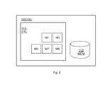
- FIG. 3 is a block diagram illustrating embodiments of a coordination unit
- FIG. 4 is a block diagram illustrating embodiments of a network node
- FIG. 5 illustrates a cluster comprising a single network node comprising several transceiver antennas in a MIMO-MU embodiment
- FIG. 6 a illustrates throughput using a SLNR precoding algorithm with ideal channel knowledge
- FIG. 6 b illustrates throughput using a SLNR precoding algorithm with practical channel estimates
- FIGS. 7 a and 7 b illustrate how throughput is improved in a simulation using the proposed methods.
- the essence of the proposed technique is a novel multi-user joint transmission scheme which takes inter-cluster interference into account.
- the precoding scheme is further based on the channel estimation error.
- the channel estimation error is obtained through a standard channel estimation procedure in combination with a setup of sounding signals which are orthogonal within each CoMP cluster and (almost) uncorrelated between CoMP clusters.
- sounding interference from other CoMP clusters usually referred to as “pilot pollution” is here desirable and actively used to estimate the channels to inter-cluster wireless devices, which are then used to avoid creating interference in the Joint Transmission also between CoMP clusters, and not only within a cluster.
- the present disclosure proposes a precoding scheme which minimizes interference power caused to wireless devices outside the cluster.
- the proposed precoder will beam form away from active wireless devices in other clusters which would otherwise have suffered from interference by the transmissions from this cluster.
- the proposed precoding is based entirely on sounding signal measurements, i.e. information which can be estimated in the channel estimation procedure.
- the proposed technique in some aspects, accounts for channel estimation quality when calculating the precoder, specifically in forming the nulls to non-desired wireless devices. Simply put, when channel estimation quality is low, the system will not try to completely cancel its own signals for non-desired UEs, since it is quite uncertain about the actual channel to this wireless device. This increases robustness of the precoding. Additionally, since channel estimation quality is known per TX antenna, it means that the precoding algorithm will know which TX antennas are usable when transmitting to a certain UE and which are not.
- FIG. 1 a illustrates one example network where the proposed precoder may be implemented.
- three base stations 110 in LTE eNodeBs, are jointly transmitting to three wireless devices 10 , in LTE UEs.
- this mode is referred to as coherent Joint TX, which is one of the defined COMP modes in LTE.
- more than one point transmits the same data blocks to a UE simultaneously.
- the UE receives a combined version of signals from the more than one signal paths from different access points.
- the jointly transmitted signal can raise an average signal to noise plus interference ratio. As a consequence, the DL transmission quality is improved.
- LTE is generally used herein as an example, the same principle may be used in other cellular systems where cell synchronization is performed in a group of cells, in particular in a 5G network.
- the base stations 110 are e.g. transmitting the same signal to one wireless device, from different antennas in different base stations 110 a .
- a number of coordinated base stations 110 and wireless devices 10 are referred to as a cluster 100 .
- the transmitting side e.g. the base station or similar network side function
- the transmitting side need to know the per-physical-resource radio channel from transmission, TX, point to receiver, RX, antenna for each Transmission point and RX antenna in the network (typically called the downlink channel).
- TX transmission
- RX point to receiver
- antenna antenna for each Transmission point and RX antenna in the network
- the downlink channel typically called the downlink channel.
- the receiver of data needs to estimate the channel to be able to demodulate the data, but here, in order to avoid interference and aim right, the transmitter needs this information as well.
- the downlink channel estimates are obtained by letting the UEs periodically or aperiodically transmit pilot (or sounding) sequences to the transmission points which receive these sequences in order to estimate the channel.
- pilot or sounding
- multiple orthogonal pilot sequences can be transmitted at the same time by several UEs within one cluster. In this way, the network can estimate the downlink channel for all Transmission points to multiple UEs at the same time (again, assuming reciprocity). This is illustrated in FIG. 1 b.
- the network needs to calculate a precoding for each physical resource (or group of physical resources) in order to transmit the D data streams from N TX antennas to the M RX antennas.
- the vector of data symbols to be simultaneously transmitted in a physical resource can be denoted:
- the downlink channel matrix is denoted H.
- the transmitted signal vector from the N TX antennas is denoted y and the received signal vector collecting the received signals from all antennas of all users in the cluster of interest is denoted z.
- ⁇ is a function chosen e.g. to maximize the average system throughput, to maximize the cell edge user throughput or to minimize the total system TX power.
- Examples of classical precoding functions are SLNR (maximizing Signal-to-Leakage-and-Noise ratio), Zero Forcing (minimizing interference).
- FIG. 1 c illustrates two clusters a and b with coordinated devices.
- the devices in the cluster are enumerated using the letter of the cluster as a suffix.
- the base stations of cluster “a” are enumerated 110 a and the wireless devices of cluster “a” are enumerated 10 a .
- the base stations in cluster “a” are transmitting they try to cancel or at least minimize the interference caused to other wireless devices 10 a within the cluster using precoding and/or beamforming.
- This interference is referred to as inter-cluster interference.
- This disclosure proposes a new precoder weight calculating algorithm which takes an estimate of the caused inter-cluster interference into account and tries to minimize such interference.
- the cluster for example the cluster in FIG. 1 a - c , comprises one or more wireless devices 10 a and one or more network nodes 110 a , wherein the one or more network nodes 110 a are transmitting in coordination to the wireless devices 10 a in the cluster using several transceiver antennas.
- the method is typically performed when network node 110 a , such as an eNodeB, is about to transmit a signal to a wireless device in the cluster.
- the method comprises scheduling S 1 the sounding sequences transmitted by the one or more wireless devices 10 a in the cluster 100 .
- the network node 110 a allocates resources e.g. time and frequency for the sounding signals and also informs the wireless devices about the resources.
- the network node is responsible for all scheduling.
- other solutions are also possible, as discussed below.
- the scheduling S 1 typically comprises scheduling orthogonal sounding sequences within each cluster 100 .
- the network can estimate the downlink channel for all transmission points to multiple wireless devices at the same time (again, assuming reciprocity).
- the downlink channel matrix is denoted H.
- the coordination unit receives, for each transceiver antenna in each of the one or more network nodes 110 a , a signal comprising pre-defined sounding sequences transmitted by the one or more wireless devices 10 a of the cluster 100 and sounding channel interference from one or more wireless devices 10 b outside the cluster 100 .
- Each antenna corresponds to a transmission point.
- the antennas may be located in one or several network nodes. Because the sounding signals are known to the network nodes this enables calculation of the physical channel from the network nodes' transmit antennas to the wireless devices' receive antennas for a certain resource r at a certain time t. The time may be referred to as a transmission time interval, TTI.
- the coordination unit estimates S 4 , from the received signal, the sounding channel interference from the wireless devices 10 b outside the cluster.
- the network node estimates the channel, using the known sounding sequences.
- the sounding scheduled such that sounding sequences in different clusters have a correlation below a threshold.
- the sounding sequences are uncorrelated, or at least almost uncorrelated, between clusters.
- the network node may identify the sum of the “unknown” wireless devices that are also transmitting sounding signals.
- the method further comprises determining S 5 downlink precoder weights, for use when transmitting from the transceiver antennas of the cluster 100 , using the estimated sounding channel interference from the one or more wireless devices 10 b outside the cluster 100 .
- This step implies utilizing the knowledge about possible “unknown” wireless devices in order to avoid disturbing them.
- the precoder is estimated based on the estimated channel between the transmitters and receiver of the transmission in accordance with prior art, wherein the estimated sounding channel interference is also taken into account as an additional factor.
- the determining S 5 implies that the precoder weights are determined such that the interference that the transmissions from the transceiver antennas will cause to the wireless devices 10 b outside the cluster 100 is minimized or reduced. Stated differently, the precoder is set to optimize the channel to the receiver or receivers, while still cancelling the interference both for wireless devices inside and outside the own cluster.
- the method comprises the step of transmitting S 6 data using the determined S 5 precoder weights. This implies that the network node transmits data using the calculated precoder. Because the precoder was selected to consider even other cluster's wireless devices, the inter-cluster interference is reduced.
- the sounding channel interference may be estimated in different ways.
- One example embodiment is to calculate S 4 a sounding channel interference covariance estimates of the estimated sounding channel interference.
- the determining S 5 comprises determining S 5 a precoder weights based on the sounding channel interference covariance estimates. This implies that the sounding channel interference covariance is estimated and that the precoder is calculated using the sounding channel interference covariance as one input value.
- the covariance represents the spatial statistics of the intercluster interference.
- H (r,t) The physical channel from the eNodeB TX antennas to the UE RX antennas for a certain resource r at a certain time t is denoted H (r,t) and since the channel is assumed reciprocal, the channel in the reverse direction is H T (r,t).
- H T (r,t) the resource and time notation (r,t) is omitted for readability.
- the subscript U is used for the UE signals and matrices, and subscript E for the eNodeB signals.
- the channel H and the diagonal maximum TX gain is given by P E (which may be a complex rotation due to RX-TX phase differences)
- the channel estimate of H is denoted H.
- the channel from the cluster TX antennas to inter-cluster UEs i.e. UEs in other clusters
- G The channel from the cluster TX antennas to inter-cluster UEs (i.e. UEs in other clusters)
- G The channel estimates of G are not available, since the precise sounding resources of another cluster are not known by the own cluster, possibly due to slow backhaul communication between clusters.
- FIG. 6 a illustrates simulation of throughput using a SLNR precoding algorithm with ideal channel knowledge as input and FIG. 6 b illustrates the same precoder with practical channel estimates as input.
- the SLNR precoding algorithm assumes that it has ideal channel knowledge.
- SLNR precoding gives nice gains for ideal channel knowledge, FIG. 6 a , but all gains are turned into loss, FIG. 6 b , compared to the legacy serving cell transmission when practical channel estimates are used.
- the proposed technique can be extended to further comprise estimating S 3 , using received pre-defined sounding sequences, channel estimation error estimates corresponding to respective downlink channel estimates based on the received signal and wherein the determining S 5 comprises determining S 5 b precoder weights based on the estimated channel estimation error estimates.
- a typical example is that the determining S 5 implies that the precoder weights are selected such that, transmissions to wireless devices 10 b outside the cluster 100 are reduced to a higher extent for a first signal corresponding to a first channel estimation error than for a second signal corresponding to a second channel estimation error, when the first channel estimation error corresponds to a higher channel quality than the second channel estimation error.
- the method comprises calculating S 3 a channel estimation error covariance estimates, and the determining S 5 comprises determining S 5 b precoder weights based on the channel estimation error covariance estimates.
- determining S 5 downlink precoder weights implies that the precoder weights are selected such that, transmissions to wireless devices outside the cluster are reduced to a higher extent for a first signal corresponding to a first channel estimation error than for a second signal corresponding to a second channel estimation error, when the first channel estimation error corresponds to a higher channel quality than the second channel estimation error.
- step S 5 a few different potential embodiments of how the precoder may be determined in step S 5 , using a so called precoding calculation function, as well as the estimation of ⁇ H and ⁇ G are presented.
- channel estimation and inter-cluster interference channel covariance estimation follow below. However, the disclosure is not limited to this example.
- a standard channel estimation procedure is used to obtain a channel estimate ⁇ from the received samples ⁇ E on sounding resources.
- the determining S 5 comprises minimizing a sum of the estimated interference for the one or more wireless devices 10 b outside the cluster 100 , and a difference between the resulting effective channel between the transceiver antennas and the wireless devices in the cluster and a corresponding desired effective channel.
- the Interference Aware Zero Forcing precoder Using the estimates of ⁇ H + ⁇ G obtained in the channel estimation procedure, the Interference Aware Zero Forcing precoder becomes
- the determining S 5 comprises maximizing a Signal to Leakage and Noise Ratio of a channel between the transceiver antennas and the wireless devices in the cluster, wherein the maximizing comprises a regularization term which is based on the sounding channel interference estimates.
- the resulting precoder becomes
- the time aspect of the estimates was omitted for clarity.
- the UL and DL transmissions do not take place in the same time instant, and therefore the coordination unit does not have the latest information on neither channel estimates nor interference covariance estimates.
- the channel estimation filtering or extrapolation to the given time from previous sounding instants is a standard procedure outside of the scope of this disclosure.
- the timing aspect of the interference covariance estimate part will now be discussed.
- the scheduling S 1 comprises coordinating sounding sequence transmissions between the cluster 100 and at least one other cluster.
- the scheduling S 1 comprises scheduling the sounding signals a pre-defined time before a corresponding downlink transmission.
- this could be to set a fixed sounding-to-DL-transmission time gap ⁇ DL-SRS so that the UEs scheduled for sounding at time instant t ⁇ DL-SRS are exactly the same UEs being scheduled for DL transmission at time t in all clusters.
- More advanced ways to coordinate include if one cluster knows the pilot sounding resources of another cluster the former cluster could select among its own UEs that are likely to be significant victim UEs (based e.g. on pathgain/RSRP estimates to find out the most strongly interfered UEs) of the latter cluster's transmissions during the time period between two pilot sounding occasions for the latter cluster and let those selected UEs' pilot sounding collide with the pilot sounding of the latter cluster.
- the scheduling S 1 comprises scheduling sounding sequences of at least one of the wireless devices 10 a within the cluster 100 to at least partly overlap with the sounding sequences of at least one other cluster.
- the clusters' pilot sounding resources could be set up in a predetermined fashion and knowledge of that sounding pattern could be shared among multiple clusters.
- a cluster may signal another cluster the pilot sounding pattern or individual future occasions.
- the cluster comprises a single network node 110 a comprising several transceiver antennas, as illustrated in FIG. 5 .
- An application for MU-MIMO is obtained by setting the number of network nodes to one in the previous derivation, i.e. only one network point/node is included in the cluster. This would allow one point/node to partly also avoid transmitting towards victim UEs of neighboring nodes/points. This could also be referred to as a version of coordinated beamforming.
- FIG. 3 illustrates an example coordination unit 115 , according to some of the example embodiments, wherein the coordination unit 115 is configured to coordinate transmissions in a cluster comprising one or more wireless devices and one or more network nodes, wherein the one or more network nodes are transmitting in coordination to the one or more wireless devices in the cluster using several transceiver antennas.
- the coordination unit 115 comprises processing circuitry 113 configured to receive, for each transceiver antenna in each of the one or more network nodes 110 a , a signal comprising pre-defined sounding sequences transmitted by the one or more wireless devices inside the cluster and sounding channel interference from one or more wireless devices outside the cluster.
- the processing circuitry 113 is further configured to estimate, from the received signal, the sounding channel interference from the wireless devices outside the cluster.
- the processing circuitry 113 is also configured to determine downlink precoding weights, for use when transmitting from the transceiver antennas of the cluster, based on the received signal and the estimated sounding channel interference.
- the processing circuitry 113 may be any suitable type of computation unit, e.g. a microprocessor, digital signal processor, DSP, field programmable gate array, FPGA, or application specific integrated circuit, ASIC, or any other form of circuitry. It should be appreciated that the processing circuitry 113 need not be provided as a single unit but may be provided as any number of units or circuitry.
- the processing circuitry 113 may be in communication, directly or indirectly, with a radio communication interface (not shown).
- the processing circuitry 113 may be capable of executing computer program code.
- the coordination unit 115 may comprise a memory, MEM 112 .
- the memory 112 may be comprised in the processing circuitry 113 .
- a computer program may be stored in the memory 112 .
- the computer program may, when run in the coordination unit 115 , cause the coordination unit 115 to perform aspects of the method as disclosed above.
- the memory 112 can be any combination of a Random Access Memory, RAM, and a Read Only Memory, ROM.
- the memory 112 may comprise persistent storage, which, for example, can be any single one or combination of magnetic memory, optical memory, or solid state memory or even remotely mounted memory.
- the processing circuitry 113 comprises modules configured to perform the methods described above.
- the processing circuitry 113 comprises a receive module M 1 configured to receive, for each transceiver antenna in each of the one or more network nodes 110 a , a signal comprising pre-defined sounding sequences transmitted by the one or more wireless devices inside the cluster and sounding channel interference from one or more wireless devices outside the cluster.
- the processing circuitry 113 further comprises an estimation module M 5 configured to estimate, from the received signal, the sounding channel interference from the wireless devices outside the cluster.
- the processing circuitry 113 also comprises a determination module M 7 configured to determine downlink precoding weights, for use when transmitting from the transceiver antennas of the cluster, based on the received signal and the estimated sounding channel interference.
- the processing circuitry 113 may additionally comprise a transmit module M 9 configured to transmit data using the determined precoding weights.
- the processing circuitry 113 may additionally comprise an estimation and calculation module M 3 configured to estimate, using received pre-defined sounding sequences, channel estimation error estimates corresponding to respective downlink channel estimates based on the received signal, and calculate channel estimation error covariance estimates.
- the coordination unit is implemented in a computer cloud.
- the coordination unit is implemented in a software defined network, SDN.
- the processing circuitry 113 is configured to calculate sounding channel interference covariance estimates of the estimated sounding channel interference, and to determine precoding weights based on the sounding channel interference covariance estimates.
- the processing circuitry 113 is configured to estimate, using received pre-defined sounding sequences, channel estimation error estimates corresponding to respective downlink channel estimates based on the received signal and wherein the determining comprises determining precoding weights based on the estimated channel estimation error estimates.
- the processing circuitry 113 is configured to calculate channel estimation error covariance estimates, and wherein the determining comprises determining precoding weights based on the channel estimation error covariance estimates.
- determining implies that the precoding weights are selected such that, transmissions to wireless devices outside the cluster are reduced to a higher extent for a first signal corresponding to a first channel estimation error than for a second signal corresponding to a second channel estimation error, when the first channel estimation error corresponds to a higher channel quality than the second channel estimation error.
- the processing circuitry 113 is configured to schedule the sounding sequences transmitted by the one or more wireless devices in the cluster.
- the processing circuitry 113 is configured to transmit data using the determined precoding weights.
- FIG. 4 illustrates an example network node 110 a , according to some of the example embodiments, wherein the network node 110 a is configured to coordinate transmissions in a cluster comprising one or more wireless devices and one or more network nodes 110 a , wherein the one or more network nodes 110 a are transmitting in coordination to the wireless devices in the cluster using several transceiver antennas.
- the network node 110 a comprises an embodiment of a coordination unit as described above in relation to FIG. 3 .
- the network node 110 a further comprises a communication interface 111 comprising one or more transceiver antennas, wherein the communications interface 111 is configured for communication with a wireless device.
- the communication interface 111 comprises a radio communication interface 111 a and a network communication interface 111 b.
- the radio communication interface 111 a is configured for communication with wireless devices within reach of the network node over a radio communication technology.
- the network communication interface 111 b is configured for communication with other network nodes. This communication is often wired e.g. using fiber. However, it may as well be wireless.
- the connection between network nodes is generally referred to as the backhaul.
- FIGS. 7 a and 7 b illustrate predicted gains obtained by Multi-User Joint Transmission over traditional serving cell transmission using the present invention.
- FIG. 7 a illustrates a simulation of a Multi-User Joint transmission using a custom Matlab simulator using standard 3GPP Hexagonal Hetnet models extracted from the Raptor simulator.
- FIG. 7 b illustrates mean wireless device throughput for different served traffic conditions.
- Multi-User Joint Transmission schemes based on Minimum Mean-Square-Error Zero Forcing, MMSE ZF, where inter-cluster interference is (the present invention), legend (3), and is not, legend (2), taken into account, are compared to legacy serving cell only scheduling (the typical LTE or HSPA networks today).
- the present invention is predicted to improve the mean wireless device throughput, with the improvement increasing as the served traffic, measured in data rate per area unit, increases.
- wireless terminal or “wireless device” encompass any device which is able to communicate wirelessly with another device, as well as, optionally, with an access node of a wireless network, by transmitting and/or receiving wireless signals.
- wireless device encompasses, but is not limited to: a user equipment, e.g. an LTE UE, a mobile terminal, a stationary or mobile wireless device for machine-to-machine communication, an integrated or embedded wireless card, an externally plugged in wireless card, a dongle etc.
- user equipment is sometimes used to exemplify various embodiments.
Landscapes
- Engineering & Computer Science (AREA)
- Signal Processing (AREA)
- Computer Networks & Wireless Communication (AREA)
- Power Engineering (AREA)
- Physics & Mathematics (AREA)
- Mathematical Physics (AREA)
- Mobile Radio Communication Systems (AREA)
Abstract
Description
z=Hy=HWx
γU =HP E x E
and symmetrically for the reverse direction with max UE TX gain matrix PU
γE =H T P U x U
P U P U H =|p U 2 |I
x E =Ws
where s is a vector of unity power data symbols to be transmitted simultaneously from the set of eNBs to the set of UEs, i.e.
γU =HP E Ws
z U =GP E Ws E.
ΛG =E{G H G}.
W=ƒ(Ĥ,Λ G).
ΛH =E{{tilde over (H)} H {tilde over (H)}}
W=Λ(Ĥ,Λ H,ΛG)
γE =H T P U x U +G T P I x I +e
where e is white background noise with E{eeH}=Σ, and PI is the UE TX gain matrix for the inter-cluster UEs.
where the approximately equal comes from some remaining the correlation between {tilde over (H)} and xU from the channel estimation procedure, but this correlation becomes very small for larger channel estimation processing gains.
W=(P E Ĥ H ĤP E +P EΛH P E)−1 P E Ĥ H R=P E −1(Ĥ H Ĥ+Λ H)−1 Ĥ H
∥HP E W−R∥ F 2 +∥GP E W∥ F 2
the optimal solution becomes
W=P E −1(Ĥ H Ĥ+Λ H+ΛG)−1 Ĥ H R
w :,d=argmax(eig(Ĥ d,: H Ĥ d,: ,Ĥ
where Σ is a regularization term and the argmax(eig(x,y)) notation means the eigenvector corresponding to the largest generalized eigenvalue of x and y.
w :,d=argmax(eig(Ĥ d,: H Ĥ d,: ,Ĥ
for some filter time horizon N and a delay from latest received sounding to DL transmission δ.
ΛG =E{{tilde over (G)} H {tilde over (G)}}
W=P E −1(Ĥ H Ĥ+Ĝ H Ĝ+Λ H+ΛG)−1 Ĥ H R
Claims (20)
Applications Claiming Priority (1)
| Application Number | Priority Date | Filing Date | Title |
|---|---|---|---|
| PCT/EP2015/056691 WO2016155758A1 (en) | 2015-03-27 | 2015-03-27 | Methods and arrangements for mitigating inter-cluster interference |
Publications (2)
| Publication Number | Publication Date |
|---|---|
| US20180115381A1 US20180115381A1 (en) | 2018-04-26 |
| US10476621B2 true US10476621B2 (en) | 2019-11-12 |
Family
ID=52807796
Family Applications (1)
| Application Number | Title | Priority Date | Filing Date |
|---|---|---|---|
| US15/561,969 Active US10476621B2 (en) | 2015-03-27 | 2015-03-27 | Methods and arrangements for mitigating inter-cluster interference |
Country Status (3)
| Country | Link |
|---|---|
| US (1) | US10476621B2 (en) |
| EP (1) | EP3275089A1 (en) |
| WO (1) | WO2016155758A1 (en) |
Families Citing this family (12)
| Publication number | Priority date | Publication date | Assignee | Title |
|---|---|---|---|---|
| CN105721026B (en) * | 2015-12-31 | 2019-12-17 | 华为技术有限公司 | Joint data transmission method and equipment |
| WO2018020405A1 (en) * | 2016-07-26 | 2018-02-01 | Karthik Muralidhar | Method for improving signal to noise ratio in an uplink transmission |
| EP3669465B1 (en) | 2017-08-18 | 2021-12-01 | Telefonaktiebolaget LM Ericsson (publ) | Transmission to moving receivers |
| US11848692B2 (en) * | 2017-09-28 | 2023-12-19 | Apple Inc. | Interference mitigation and multi-moment filtering |
| US11044001B2 (en) * | 2017-12-19 | 2021-06-22 | Telefonaktiebolaget Lm Ericsson (Publ) | Steering vector weighting |
| CN108768473B (en) * | 2018-04-04 | 2021-08-03 | 景晨 | Precoding method of MIMO multi-relay system with antenna correlation and channel estimation error |
| KR102543091B1 (en) * | 2018-06-15 | 2023-06-14 | 삼성전자주식회사 | Apparatus and method for integrated beamforming in wireless communication system |
| EP3857724B1 (en) | 2018-09-24 | 2024-02-07 | Telefonaktiebolaget LM Ericsson (publ) | Uplink and downlink reciprocity management of interference |
| WO2020121148A1 (en) | 2018-12-12 | 2020-06-18 | Marvell World Trade Ltd. | Physical layer protocol data unit directional transmission |
| EP4010991A1 (en) | 2019-08-09 | 2022-06-15 | Telefonaktiebolaget LM Ericsson (publ) | Technique for precoding a radio transmission |
| WO2024102036A1 (en) * | 2022-11-07 | 2024-05-16 | Telefonaktiebolaget Lm Ericsson (Publ) | Method for selecting a precoder based on measured srs interference on srs transmitted by downlink heavy traffic user equipments. |
| WO2024175168A1 (en) * | 2023-02-20 | 2024-08-29 | Telefonaktiebolaget Lm Ericsson (Publ) | Method, network node, and computer program for downlink interference suppression in an access network |
Citations (6)
| Publication number | Priority date | Publication date | Assignee | Title |
|---|---|---|---|---|
| US20080025200A1 (en) * | 2006-06-22 | 2008-01-31 | Nokia Corporation | Interference cancellation unit and interference cancellation method |
| US20120202558A1 (en) * | 2011-02-07 | 2012-08-09 | Telefonaktiebolaget L M Ericsson (Publ) | Uplink Selection Using Sounding Reference Signals in Radiocommunication Systems |
| US20120275411A1 (en) * | 2009-12-22 | 2012-11-01 | Hyung Tae Kim | Apparatus for performing comp communication using a precoded sounding reference signal, and method for same |
| US20120307772A1 (en) * | 2010-02-11 | 2012-12-06 | Pantech Co., Ltd. | Method of switching a periodic/aperiodic transmission of a channel estimation reference signal, and apparatus and method for a transmitting/receiving channel estimation reference signal using the same |
| US20130303199A1 (en) * | 2012-04-09 | 2013-11-14 | Telefonaktiebolaget L M Ericsson (Publ) | Methods and apparatus for enhancing network positioning measurement performance by managing uncertain measurement occasions |
| US20170079051A1 (en) * | 2014-05-08 | 2017-03-16 | Huawei Technologies Co., Ltd. | Channel estimation in wireless communication network node |
Family Cites Families (1)
| Publication number | Priority date | Publication date | Assignee | Title |
|---|---|---|---|---|
| US8798550B2 (en) * | 2012-05-11 | 2014-08-05 | Telefonaktiebolaget L M Ericsson (Publ) | Methods and arrangements for CSI reporting |
-
2015
- 2015-03-27 US US15/561,969 patent/US10476621B2/en active Active
- 2015-03-27 EP EP15713863.7A patent/EP3275089A1/en not_active Withdrawn
- 2015-03-27 WO PCT/EP2015/056691 patent/WO2016155758A1/en active Application Filing
Patent Citations (6)
| Publication number | Priority date | Publication date | Assignee | Title |
|---|---|---|---|---|
| US20080025200A1 (en) * | 2006-06-22 | 2008-01-31 | Nokia Corporation | Interference cancellation unit and interference cancellation method |
| US20120275411A1 (en) * | 2009-12-22 | 2012-11-01 | Hyung Tae Kim | Apparatus for performing comp communication using a precoded sounding reference signal, and method for same |
| US20120307772A1 (en) * | 2010-02-11 | 2012-12-06 | Pantech Co., Ltd. | Method of switching a periodic/aperiodic transmission of a channel estimation reference signal, and apparatus and method for a transmitting/receiving channel estimation reference signal using the same |
| US20120202558A1 (en) * | 2011-02-07 | 2012-08-09 | Telefonaktiebolaget L M Ericsson (Publ) | Uplink Selection Using Sounding Reference Signals in Radiocommunication Systems |
| US20130303199A1 (en) * | 2012-04-09 | 2013-11-14 | Telefonaktiebolaget L M Ericsson (Publ) | Methods and apparatus for enhancing network positioning measurement performance by managing uncertain measurement occasions |
| US20170079051A1 (en) * | 2014-05-08 | 2017-03-16 | Huawei Technologies Co., Ltd. | Channel estimation in wireless communication network node |
Non-Patent Citations (6)
| Title |
|---|
| 3GPP TSG-RAN WG1#74, R1-133213, Barcelona, Spain, Aug. 19-23, 2013, Beamforming with Coordinated Sounding (BF-CoS) exploiting TDD channel reciprocity, DAC-UPC, IAESI, pp. 1-10. |
| Axel Muller et al., Interference-Aware RZF Precoding for Multi Cell Downlink Systems, arXiv:1408.2232v2 [cs.IT] Apr. 10, 2015, pp. 1-15. |
| PCT International Search Report, dated Dec. 21, 2015, in connection with International Application No. PCT/EP2015/056691, all pages. |
| PCT Written Opinion, dated Dec. 21, 2015, in connection with International Application No. PCT/EP2015/056691, all pages. |
| Shirish Nagaraj, et al., Coordinated Beamforming in Clustered HetNets: System Design and Performance Evaluation, IEEE WCNC 2014-Workshop on Interference and Design Issues for Future Heterogeneous Networks, pp. 70-75. |
| Shirish Nagaraj, et al., Coordinated Beamforming in Clustered HetNets: System Design and Performance Evaluation, IEEE WCNC 2014—Workshop on Interference and Design Issues for Future Heterogeneous Networks, pp. 70-75. |
Also Published As
| Publication number | Publication date |
|---|---|
| WO2016155758A1 (en) | 2016-10-06 |
| EP3275089A1 (en) | 2018-01-31 |
| US20180115381A1 (en) | 2018-04-26 |
Similar Documents
| Publication | Publication Date | Title |
|---|---|---|
| US10476621B2 (en) | Methods and arrangements for mitigating inter-cluster interference | |
| US11451274B2 (en) | Adaptive downlink multi user multiple input multiple output (MU-MIMO)precoding using uplink signal subspace tracking for active antenna systems AAS | |
| Atzeni et al. | Distributed precoding design via over-the-air signaling for cell-free massive MIMO | |
| US11411621B2 (en) | Uplink and downlink reciprocity management of interference | |
| US9148208B2 (en) | Antenna selection codebook for full dimensional MIMO systems | |
| EP2836039B1 (en) | Mimo wireless communication system, transmission method and device | |
| US10659126B2 (en) | Method for feeding back CSI information in wireless communication system and device therefor | |
| EP3501115B1 (en) | Radio node and method therein for determining precoders | |
| CN106664131A (en) | Base station, user equipment and radio communication network | |
| US20180054244A1 (en) | Method for feeding back csi information on basis of csi reporting type in wireless communication system, and device thereof | |
| US9647734B2 (en) | Large-scale fading coefficient estimation in wireless massive MIMO systems | |
| CN112823478B (en) | Multi-user pairing and SINR calculation based on relative beam power for codebook-based DL MU-MIMO | |
| US20160381583A1 (en) | Radio base station, user terminal and radio communication method | |
| US20180138951A1 (en) | Antenna selection for massive mimo systems related application | |
| WO2020115523A1 (en) | Two-dimensional subspace tracking and beamforming for active antenna systems | |
| Tang et al. | Downlink path-based precoding in FDD massive MIMO systems without CSI feedback | |
| WO2020142794A2 (en) | Methods and apparatus for channel estimation and precoding with incomplete channel observation and channel state information feedback | |
| Bhamri et al. | Improving MU-MIMO performance in LTE-(advanced) by efficiently exploiting feedback resources and through dynamic scheduling | |
| EP3669465A1 (en) | Transmission to moving receivers | |
| WO2023211323A1 (en) | Method and one or more network entities for improved uplink channel estimation | |
| Apelfröjd et al. | Coded Reference Signals for Massive MIMO Channel Estimation in FDD Systems | |
| CN116601877A (en) | Channel state change estimation and SINR penalty calculation for MU-MIMO pairing | |
| KR20240094949A (en) | Electronic device and method for processing received signal in wireless communication system | |
| KR101005539B1 (en) | Transmit antenna selection method in multi-cell communication system, and wireless communication device thereof | |
| KR20120071115A (en) | Method for controlling interference from adjacent cells in cellular system |
Legal Events
| Date | Code | Title | Description |
|---|---|---|---|
| AS | Assignment |
Owner name: TELEFONAKTIEBOLAGET LM ERICSSON (PUBL), SWEDEN Free format text: NUNC PRO TUNC ASSIGNMENT;ASSIGNORS:JONGREN, GEORGE;LINCOLN, BO;SIGNING DATES FROM 20150427 TO 20150716;REEL/FRAME:043707/0438 |
|
| FEPP | Fee payment procedure |
Free format text: ENTITY STATUS SET TO UNDISCOUNTED (ORIGINAL EVENT CODE: BIG.); ENTITY STATUS OF PATENT OWNER: LARGE ENTITY |
|
| STPP | Information on status: patent application and granting procedure in general |
Free format text: FINAL REJECTION MAILED |
|
| STPP | Information on status: patent application and granting procedure in general |
Free format text: NOTICE OF ALLOWANCE MAILED -- APPLICATION RECEIVED IN OFFICE OF PUBLICATIONS |
|
| STPP | Information on status: patent application and granting procedure in general |
Free format text: PUBLICATIONS -- ISSUE FEE PAYMENT RECEIVED |
|
| STCF | Information on status: patent grant |
Free format text: PATENTED CASE |
|
| MAFP | Maintenance fee payment |
Free format text: PAYMENT OF MAINTENANCE FEE, 4TH YEAR, LARGE ENTITY (ORIGINAL EVENT CODE: M1551); ENTITY STATUS OF PATENT OWNER: LARGE ENTITY Year of fee payment: 4 |