US1047648A - Railway-rail clamp for metallic ties. - Google Patents
Railway-rail clamp for metallic ties. Download PDFInfo
- Publication number
- US1047648A US1047648A US69272612A US1912692726A US1047648A US 1047648 A US1047648 A US 1047648A US 69272612 A US69272612 A US 69272612A US 1912692726 A US1912692726 A US 1912692726A US 1047648 A US1047648 A US 1047648A
- Authority
- US
- United States
- Prior art keywords
- tie
- rail
- bolt
- clamping member
- movable
- Prior art date
- Legal status (The legal status is an assumption and is not a legal conclusion. Google has not performed a legal analysis and makes no representation as to the accuracy of the status listed.)
- Expired - Lifetime
Links
- 230000001154 acute effect Effects 0.000 description 8
- 241000251468 Actinopterygii Species 0.000 description 3
- 239000002184 metal Substances 0.000 description 3
- 238000010276 construction Methods 0.000 description 2
- 230000000284 resting effect Effects 0.000 description 2
- 230000000694 effects Effects 0.000 description 1
Images
Classifications
-
- E—FIXED CONSTRUCTIONS
- E01—CONSTRUCTION OF ROADS, RAILWAYS, OR BRIDGES
- E01B—PERMANENT WAY; PERMANENT-WAY TOOLS; MACHINES FOR MAKING RAILWAYS OF ALL KINDS
- E01B13/00—Arrangements preventing shifting of the track
- E01B13/02—Rail anchors
Definitions
- the object of my invention is to provide a device of simple, durable and inexpensive rail to the tie; and further in this connection to provide a device of this class 1 in which the impactof heavy trains upon the rail will haveonly a minimum tendency to loosen the rail clamping device whereby the said rail clamping device 'may be held 20.
- My inventlon consists m'certain details, in the construction, arrangement'and combination of the various parts of the device,
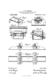
- Figure l shows a perspective view ofthe two clamping members in position with relation to each other as required in use.
- Fig. 2 shows a side elevation of two adjoining railway rails, a fish plate anda metallic tie having my improved 'clampingdevice applied thereto.
- Fig. 3 shows a detail, transverse sectional view of my improved clamplng device applied toa metallic tie'and to a railway rail.
- Fig. 4 shows a sectional view on the line 4-4 of Fig. 3.
- Fig. 5 shows a side ele.-.
- My improved clamping device comprises two members, one hereinafter called the stationary clamping member and the other the movable member.
- the stationary clamping, member is preferably made'of plate'metal and comprises a base 15 having its ends 16 bent downwardly at right angles to the base and also having portionsof the base bent downwardly adjacent to the ends 16, said portions being indicated. by the numeral 17.
- This base is designed to rest on the upturned sides llofa metal tie and the ends 16 are to. stand against the outer surfaces of said sides 11 while theparts 17 stand close to but slightly spaced apart from the inner surfaces of the sides 11.
- arail engaging member 18 shaped to extend upwardly around the base of a rail and then inwardly toward the web of a rail and then upwardly :as clearly shown in Fig. 3.
- This rail engag-' ingmember mayobviously be-made of a size and shape tofit. against a rail or it may be .so shaped as to ,fit against a fish plate 1 1 resting aga nst. a rail.
- the other; rail clamping member comprises a base portion 19 designedeto extend under the base portion15an'd to closely againsta part ofsaid base 15.
- This base portion is'provided with a rail engaging member'20 similarto the rail engaging member 18,'and it is also provided at itslower portionat a point be low the base. portion 15 witha cylindrical bolt engaging portion 21, the latter being extended at an acute angle relative to a line extended longitudinally of the rail engaging member. V
- a bolt comprising a straight, round, central portion 22, a flattened end portion 28' having inclined shoulders 24 and also having square shoulders 25.
- the other end of the bolt is screw threaded at 26
- To provide ior. receiving this bolt one o'f the end portions 16 of the base 15 is provided with an, oblong slot 27 and the other with around opening 28.
- the metallictie is also provided onone sidewith an oblong slot 29 and ion the other side with a round opening 30.
- a beveled washer 31 and a nut 32 are also provided for the screw threaded end of the bolt.
- the stationary clamping member is first placed in position on the tie resting in the recess thereof and against the shoulders 12. Then the movable clamping member is placed in position to engage the side of the rail and the under side of the base 15.
- the rail engaging portion of the stationary clamping member is preferably against the outer surface of the rail while the movable clamping member is against the inner surface thereof.
- the bolt When said parts are in this position the bolt may be readily and easily extended through all four of said openings and through said cylindrical portion until the inclined shoulders 24 are within the interior of the metallic tie and the shoulders 25 are in engagement with one end of the cylindrical portion 21. Then the washer 31 and the nut 82 are placed on the projecting end of the bolt and the nut is screwed up tight. The effect of this will be first to have the shoulder 25 engage the end of the cylindrical portion 21 and thereby move the movable clamping member longitudinally of the rail a slight distance.
- the inclined shoulder 24 will obviously prevent a longitudinal movement of the bolt in a direction that would tend to loosen the movable clamping member. Therefore after the nut has been firmly screwed up and in the event that it should become loosened the movable clamping member will be so firmly gripped to the rail and the bolt will bind against the tie to such an extent that the tendency for the movable member to become wholly detached on account of the successive impacts of a train upon the rail is minimized and even if the nut were wholly missing, in all probability the bolt would remain in position and of itself prevent the detachment or re mo-val of the movable rail clamping member.
- movable rail clamping member provided with a bolt receiving sleeve on its under surface, and a bolt extended through the openlngs 1n the t1e and in the stationary member and through the sleeve in the movable member, and said bolt being provided with a shoulder to engage the movable clamping member, said bolt also being extended through said parts at an acute angle relative to a line transverse of the tie.
- said bolt also being extended through said parts atan acute angle relative to a line transverse of the tie, an inclined shoulder, and a nut on theend of the bolt'opposite from said shoulder.
- a metallic rail way tie comprising a base and upwardly extended side members, one of said side members having an oblong slot and the other a round opening, a stationaryclamping member comprising a baseplate designed to rest on the sides of the tie, and end pieces designed to overlap the sides of the tie, a rail engaging member, one of said end pieces being provided with an oblong slot and the other with a round opening, a
- movable rail engaging member comprislng a base portion designed to extend under the base portion of the stationary member and having a cylindrical bolt receiving member at its lower end arranged at an acute angle relative to a transverse line through the tie and also having a rail engaging member at its upper portion, a bolt having its central portion designed-to extend through said cylindrical bolt receiving portion and being formed with a fiat end having shoulders to engage said cylindrical bolt re- Gopies of this patent may be obtained for volving portion andv also having inclined shoulders adjacent to the aforesaid shoul-' ders to engage the adjacent portion of the tie, said bolt being designed tobe extended through the oblong openings, then through the cylindrical bolt receiving portion and then through the round openings at an, acute angle relative to a transverse line,
- way tie comprising a base andupwardly extended side, members, one of said "side members having an oblong slot and the other a round opening, a stationary clamping member comprising a base plate designed to rest on the sides of the tie and end pieces designed to overlap the sides of the tie, a" rail engaging member, one .of said end pieces being-provided with an obe long slot and the other witha round open.
- a movable rail: engaging member comprising a base portion designed to extend under the base portion of the stationary member and having a cylindrical bolt receiving member at its lower end arranged at an acute angle relative to a transverse line through the tie and also having a rail engaging member at its upper portion, a bolt having its central portion designed to extend through said cylindrical bolt receiving portion and being formed with a flat end having shoulders to engage said cylindrical bolt receiving portion and also having inclined shoulders adjacent to the aforesaid shoulders to engage the adjacentportion of the tie, said bolt being designed to be extended through the oblong openings,
Landscapes
- Engineering & Computer Science (AREA)
- Mechanical Engineering (AREA)
- Architecture (AREA)
- Civil Engineering (AREA)
- Structural Engineering (AREA)
- Clamps And Clips (AREA)
Description
F. M. JOHNSTON. RAILWAY RAIL CLAMPFOR METALLIC TIES. APPLICATION FILED APR. 23, 1912.
1,047Q648. Patented Dec. 17, 1912.
idifnesses Jmen/ or COLUMBIA PLANOGRAPH cu.. WASHINGTON. u c.
FRANK M. JOHNSTON, OF BooNE, IOWA.
I RAILWAY-RAIL CLAMP r03 METALLIC TIES.
specification of Letters Patent. 2 Patented Dec. 17, 1912 Application filed April23, 1912. Serial No. 692,726.
To. all whom time concern:
Beit known that I, FRANK M; J oHNsToN,
-acitizen of the United States, residing at Boone, in the county of'Boone and State of Iowa, have invented a certain new and useful Railway-Rail Clamp for Metallic Ties, of which the following .is a specification. l
/ construction forreadily and easily 'clamp ing a railway rall' to a metallic tie in such a mann er as to firmly and securely hold the The object of my invention is to provide a device of simple, durable and inexpensive rail to the tie; and further in this connection to provide a device of this class 1 in which the impactof heavy trains upon the rail will haveonly a minimum tendency to loosen the rail clamping device whereby the said rail clamping device 'may be held 20.
tightly to the rail and to the tieeven after considerable use and even in the event that g the nut on the clamping device should become loosened.
My inventlon consists m'certain details, in the construction, arrangement'and combination of the various parts of the device,
whereby the objects contemplated are attained, as hereinafter more fully set forth, pointed out in my claims and illustrated in.
the accompanying drawings, in which:
Figure l shows a perspective view ofthe two clamping members in position with relation to each other as required in use. Fig. 2 shows a side elevation of two adjoining railway rails, a fish plate anda metallic tie having my improved 'clampingdevice applied thereto. Fig. 3 shows a detail, transverse sectional view of my improved clamplng device applied toa metallic tie'and to a railway rail. Fig. 4 shows a sectional view on the line 4-4 of Fig. 3. Fig. 5 shows a side ele.-.
shouldersl2 to thereby pre'vent'late'ral movementof the rail relative to the tie. The por tions of rails that are shown are of the ordinary formand are indicated by the reference numeral 13. and the fish plates shown in some of the views are indicated by the numeral 14.
My improved clamping device comprises two members, one hereinafter called the stationary clamping member and the other the movable member. The stationary clamping, member is preferably made'of plate'metal and comprises a base 15 having its ends 16 bent downwardly at right angles to the base and also having portionsof the base bent downwardly adjacent to the ends 16, said portions being indicated. by the numeral 17. This base is designed to rest on the upturned sides llofa metal tie and the ends 16 are to. stand against the outer surfaces of said sides 11 while theparts 17 stand close to but slightly spaced apart from the inner surfaces of the sides 11. 'Formed integral with one side of the base 15 is arail engaging member 18 shaped to extend upwardly around the base of a rail and then inwardly toward the web of a rail and then upwardly :as clearly shown in Fig. 3. This rail engag-' ingmember mayobviously be-made of a size and shape tofit. against a rail or it may be .so shaped as to ,fit against a fish plate 1 1 resting aga nst. a rail. The other; rail clamping member comprisesa base portion 19 designedeto extend under the base portion15an'd to closely againsta part ofsaid base 15. This base portion is'provided with a rail engaging member'20 similarto the rail engaging member 18,'and it is also provided at itslower portionat a point be low the base. portion 15 witha cylindrical bolt engaging portion 21, the latter being extended at an acute angle relative to a line extended longitudinally of the rail engaging member. V
For the purpose of holding the clamping members firmly against a rail and also for the purpose of holding them in position,
relative to the-metallic; railway tie, I have provided a bolt comprising a straight, round, central portion 22, a flattened end portion 28' having inclined shoulders 24 and also having square shoulders 25. The other end of the bolt is screw threaded at 26 To provide ior. receiving this bolt one o'f the end portions 16 of the base 15 is provided with an, oblong slot 27 and the other with around opening 28. The metallictie is also provided onone sidewith an oblong slot 29 and ion the other side with a round opening 30. A beveled washer 31 and a nut 32 are also provided for the screw threaded end of the bolt.
In practical operation the stationary clamping member is first placed in position on the tie resting in the recess thereof and against the shoulders 12. Then the movable clamping member is placed in position to engage the side of the rail and the under side of the base 15. The rail engaging portion of the stationary clamping member is preferably against the outer surface of the rail while the movable clamping member is against the inner surface thereof. When the parts are in this position the two oblong openings in the end 16 and in the tie are in line with each other and the round openings in the other end 16 and in the other side of the tie are also in line with each other and all of these openings are in line with the cylindrical part 21 of the movable rail clamping member. When said parts are in this position the bolt may be readily and easily extended through all four of said openings and through said cylindrical portion until the inclined shoulders 24 are within the interior of the metallic tie and the shoulders 25 are in engagement with one end of the cylindrical portion 21. Then the washer 31 and the nut 82 are placed on the projecting end of the bolt and the nut is screwed up tight. The effect of this will be first to have the shoulder 25 engage the end of the cylindrical portion 21 and thereby move the movable clamping member longitudinally of the rail a slight distance. It will also move it toward the rail; that is to say, the movable clamping member will slide in the direction of the longitudinal axis of the bolt toward the nut, thereby firmly clamping a rail between the two rail engaging members, and second, this movement of the bolt and the movable member will cause the inclined shoulder 24 that is nearest to the side of the rail that is engaged by the movable clamping member to press firmly against the end of the slot in the tie and in the end 16 that is adjacent to the side of the rail on which the movable clamping member is placed, as clearly shown in Fig. 1, so that said bolt will bind against the tie at said end of the slot therein. The other end of the bolt will also bind against the same side of the round opening in the tie. The inclined shoulder 24 will obviously prevent a longitudinal movement of the bolt in a direction that would tend to loosen the movable clamping member. Therefore after the nut has been firmly screwed up and in the event that it should become loosened the movable clamping member will be so firmly gripped to the rail and the bolt will bind against the tie to such an extent that the tendency for the movable member to become wholly detached on account of the successive impacts of a train upon the rail is minimized and even if the nut were wholly missing, in all probability the bolt would remain in position and of itself prevent the detachment or re mo-val of the movable rail clamping member. By this arrangement it is obvious that only a single bolt and nut is required for holding together the two clamping members relative to the rail and also for holding the clamping members firmly in position relative to the tie. A transverse movement of the stationary clamping member relative to. the tie is prevented by means of the ends 1.6 and the lugs 17. There is however a slight play permitted between the upper edges of the sides 11 of the tie and the said ends and lugs 16 and 17 This slight amount of play permits of a slight springing movement of the sides of the tie when a heavy train is drawn upon the rail above the tie so that the impact is somewhat cushioned on account of the resiliency of the sides of the metal tie. The stationary plate also serves the additional function of preventing movement to any great extent of the sides of the tie either inwardly or out wardly.
I claim as my invention:
1. The combination with a railway tie, of a stationary and a movable rail clamping member and a bolt extending through the tie at an acute angle relative to a transverse line through the tie, said bolt being connected wit-h the movable rail clamping member.
2. The combination with a metallic tie having openings in its sides, of a stationary rail clamping member designed to rest on the tie and provided with end portions designed to rest adjacent to the sides of the tie and also provided with bolt openings, a
movable rail clamping member provided with a bolt receiving sleeve on its under surface, and a bolt extended through the openlngs 1n the t1e and in the stationary member and through the sleeve in the movable member, and said bolt being provided with a shoulder to engage the movable clamping member, said bolt also being extended through said parts at an acute angle relative to a line transverse of the tie.
3. The combination with a metallic tie having openings in its sides, of a stationary rail clamping member designed to rest on the tie and provided with end portions designed to rest adjacent to the sides of the tie and also provided with bolt openings, a movable rail clamping member provided with a bolt receiving sleeve on its under surface and a bolt extended through the openings in the tie and in the stationary member through the sleeve in the movable member and said bolt being provided with a shoulder to engage the movable.
clamping member, said bolt also being extended through said parts atan acute angle relative to a line transverse of the tie, an inclined shoulder, and a nut on theend of the bolt'opposite from said shoulder.
4. The combination with a metallic tie having openings in its sides, of a stationary rail clamping member designed to reston relative to a line transverse of the tie, the
end of the bolt adjacent to said shoulder being flat and the opening in the tie and in the adjacent end of the stationary clamping member being formed oblong to prevent rotary movement of the bolt and to permit longitudinal sliding movement thereof.
5. The combination with a metallic rail way tie, comprising a base and upwardly extended side members, one of said side members having an oblong slot and the other a round opening, a stationaryclamping member comprising a baseplate designed to rest on the sides of the tie, and end pieces designed to overlap the sides of the tie, a rail engaging member, one of said end pieces being provided with an oblong slot and the other with a round opening, a
movable rail engaging member comprislng a base portion designed to extend under the base portion of the stationary member and having a cylindrical bolt receiving member at its lower end arranged at an acute angle relative to a transverse line through the tie and also having a rail engaging member at its upper portion, a bolt having its central portion designed-to extend through said cylindrical bolt receiving portion and being formed with a fiat end having shoulders to engage said cylindrical bolt re- Gopies of this patent may be obtained for ceiving portion andv also having inclined shoulders adjacent to the aforesaid shoul-' ders to engage the adjacent portion of the tie, said bolt being designed tobe extended through the oblong openings, then through the cylindrical bolt receiving portion and then through the round openings at an, acute angle relative to a transverse line,
' 6. Thecombination with a metallic rail- 1 through the tie, and a nut on said bolt.
way tie, comprising a base andupwardly extended side, members, one of said "side members having an oblong slot and the other a round opening, a stationary clamping member comprising a base plate designed to rest on the sides of the tie and end pieces designed to overlap the sides of the tie, a" rail engaging member, one .of said end pieces being-provided with an obe long slot and the other witha round open.
ing, a movable rail: engaging member comprising a base portion designed to extend under the base portion of the stationary member and having a cylindrical bolt receiving member at its lower end arranged at an acute angle relative to a transverse line through the tie and also having a rail engaging member at its upper portion, a bolt having its central portion designed to extend through said cylindrical bolt receiving portion and being formed with a flat end having shoulders to engage said cylindrical bolt receiving portion and also having inclined shoulders adjacent to the aforesaid shoulders to engage the adjacentportion of the tie, said bolt being designed to be extended through the oblong openings,
then through the cylindrical bolt receiving portion and then through the round openings at an acute angle relative to a transverse line through the tie, a nut on said,
bolt, and two downwardly extended lugs on the base of the stationary plate designed to stand slightly spaced apart from the inner surface of the tie sides. 1- a DesiMoines, Iowa, April 12, 1912.
F. M. JOHNSTON. Witnesses: a
C. H. CRooKs," 0. E. S ATER.
five cents each, by addressing the \Commissionerof Patents,
Washington, D. C.
Priority Applications (1)
| Application Number | Priority Date | Filing Date | Title |
|---|---|---|---|
| US69272612A US1047648A (en) | 1912-04-23 | 1912-04-23 | Railway-rail clamp for metallic ties. |
Applications Claiming Priority (1)
| Application Number | Priority Date | Filing Date | Title |
|---|---|---|---|
| US69272612A US1047648A (en) | 1912-04-23 | 1912-04-23 | Railway-rail clamp for metallic ties. |
Publications (1)
| Publication Number | Publication Date |
|---|---|
| US1047648A true US1047648A (en) | 1912-12-17 |
Family
ID=3115919
Family Applications (1)
| Application Number | Title | Priority Date | Filing Date |
|---|---|---|---|
| US69272612A Expired - Lifetime US1047648A (en) | 1912-04-23 | 1912-04-23 | Railway-rail clamp for metallic ties. |
Country Status (1)
| Country | Link |
|---|---|
| US (1) | US1047648A (en) |
-
1912
- 1912-04-23 US US69272612A patent/US1047648A/en not_active Expired - Lifetime
Similar Documents
| Publication | Publication Date | Title |
|---|---|---|
| US1065595A (en) | Rail-holding device. | |
| US1018305A (en) | Combined tie and track-fastening. | |
| US1042484A (en) | Nut-lock. | |
| US948496A (en) | Railway-tie rod. | |
| US1196339A (en) | Rail clamping and fastening device. | |
| US1067438A (en) | Rail-fastener. | |
| US1069970A (en) | Rail-joint. | |
| US1130797A (en) | Rail-fastener. | |
| US976816A (en) | Means for fastening rails and preventing the spreading thereof. | |
| US1022984A (en) | Automatic continuous rail-joint. | |
| US1158919A (en) | Railroad-tie. | |
| US1213128A (en) | Rail-anchor. | |
| US1013138A (en) | Railway-tie and fastener. | |
| US1082376A (en) | Bolt. | |
| US1206389A (en) | Tie-plate. | |
| US785647A (en) | Rail tie and fastening. | |
| US850262A (en) | Rail clamp or fastening. | |
| US260446A (en) | Device for connecting rails | |
| US993455A (en) | Rail-anchor. | |
| US1263169A (en) | Nut-lock. | |
| US439722A (en) | Rail-joint | |
| US1191181A (en) | Tie and rail-fastener. | |
| US998010A (en) | Rail-clamping chair. | |
| US1250850A (en) | Railway-rail fastening. | |
| US956779A (en) | Metal railway-tie. |