US1047235A - Electric-arc lamp. - Google Patents
Electric-arc lamp. Download PDFInfo
- Publication number
- US1047235A US1047235A US63627311A US1911636273A US1047235A US 1047235 A US1047235 A US 1047235A US 63627311 A US63627311 A US 63627311A US 1911636273 A US1911636273 A US 1911636273A US 1047235 A US1047235 A US 1047235A
- Authority
- US
- United States
- Prior art keywords
- globe
- arc
- lamp
- electric
- chamber
- Prior art date
- Legal status (The legal status is an assumption and is not a legal conclusion. Google has not performed a legal analysis and makes no representation as to the accuracy of the status listed.)
- Expired - Lifetime
Links
- 238000010891 electric arc Methods 0.000 title description 4
- 239000007789 gas Substances 0.000 description 8
- 230000029058 respiratory gaseous exchange Effects 0.000 description 6
- OKTJSMMVPCPJKN-UHFFFAOYSA-N Carbon Chemical compound [C] OKTJSMMVPCPJKN-UHFFFAOYSA-N 0.000 description 4
- 230000009471 action Effects 0.000 description 4
- 229910052799 carbon Inorganic materials 0.000 description 4
- 239000003517 fume Substances 0.000 description 4
- 239000010425 asbestos Substances 0.000 description 3
- 229910052895 riebeckite Inorganic materials 0.000 description 3
- 239000000126 substance Substances 0.000 description 3
- 244000038594 Phyllanthus urinaria Species 0.000 description 1
- 238000005266 casting Methods 0.000 description 1
- 238000004140 cleaning Methods 0.000 description 1
- 238000000034 method Methods 0.000 description 1
- 230000004048 modification Effects 0.000 description 1
- 238000012986 modification Methods 0.000 description 1
Images
Classifications
-
- H—ELECTRICITY
- H05—ELECTRIC TECHNIQUES NOT OTHERWISE PROVIDED FOR
- H05B—ELECTRIC HEATING; ELECTRIC LIGHT SOURCES NOT OTHERWISE PROVIDED FOR; CIRCUIT ARRANGEMENTS FOR ELECTRIC LIGHT SOURCES, IN GENERAL
- H05B31/00—Electric arc lamps
- H05B31/003—Electric arc lamps of a special type
- H05B31/0036—Electric arc lamps of a special type for projection, copying or stage lighting
Definitions
- My invention relates to improvements in electric arc lamps of the inclosed type burning chemically compounded or mineralized carbons, and it is more particularly applicable to lamps as described in my U. S. Patent No. 935,518 of September 28, 1909.
- Such devices for protecting a tube or flue from wind action are well known in connection with stove or furnace chimneys, and any such eflicient device may be applied on a suitably reduced scale.
- the tube or channel may terminate in a short tube or channel at right angles to it; but it is to be understood that I do not confine my self to this or any particular form.
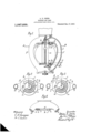
- Figure 1 shows a part section of a lamp.
- Fig. 2 is an upward view from the section A B Fig. 1.
- Fig. 3 is a similar view of a modification and
- Fig. 4 is an elevation of the same.
- a is a transparent or translucent chamber in which the electrodes are disposed and which communicates. at eachend with draft chambers 72 and 0 formed in the top and bottom. portions of the lamp casing. Passages d and e interconnect the chambers b c and a globe surrounds the chamber a.
- At the top of the lamp inclosure g is an annular groove or channel 72. having an opening 5 communicating with the chamber 72. The channel 72. is closed bye cover j the globe frosting on a ring of asbestos It.
- the globe is connected at its upper end in any suitable way to the upper part of the lamp inclosure. At its lower end the globe rests on a ring of asbestos It: carried by a metallic ring M supported on the lower part of the lamp inclosure.
- This ring as shown, 'has an upper part m having a groove to receive the asbestos ring 70, an inner flange m and an outer flange
- the inner flange is provided with a number of openings on connecting. the interior of the globe with the outer atmosphere in the manner shown in Fig. 1.
- the flange m projects across the plane of the openings m so that gases passing from the globe will follow a sinuous course in the manner indicated by the arrows.
- the flange wa thus protects or shields the outlet openings m.' Any communication between the outside and the arc chamber a is through the draft chamber 6, the opening i, the tube or channel h, the opening Z, the globe f and the holes m.
- the hot gases expelled from the arc inclosure will by reason of their smaller density tend to remain at the top of the lamp.
- a limited amount of air will be blown through the holes m onone side and out through the holes on the opposite side but the pressure in the outer globe cannot be raised suiiiciently to force fumes into the mechanism, and any circulation of wind within the outer globe will take place substantially at the bottom of the globe not afiecting the stratum of hot gases at the top of the globe.
- the lamp is made as airtight as possible.
- the hole through which the upper carbon passes from the mechanism to the arc chamber is made as closely fitting as is consistent with freedom in Work.
- the opening .2 is in communication with. the atmosphere through a wind screen 0 instead of through the space between the globes.
- the wind screen 0 is formed by casting corresponding projections or lugs on the inclosure g and the cover jwhich 1s held 111 place by wlng nuts n enabling' its ready removal and easy cleaning ofthe channel it and the wind screen 0.
- What I claim is 1 In an electric arc lamp for burning mineralized carbons, the combination with an arc-inclosing chamber, of draft chambers above and below the arcinclosingchamber and communicating therewith, a conduit outside the arc-inclosing chamber connect ing the upper and lower draft chambers through which the arc gases pass and in which deposit takes place, a lamp casing having an opening through which the upper carbon is fed and which is approximately filled by said carbon, a breathing passage having an inlet connected with the upper draft chamber and an outlet opening, means for connect-ing the outlet opening with the outer atmosphere, and a wind shield at-the exit end of the connection for preventing'rise of pressure in the draft chambers due to the rise of atmospheric pressure outside the lamp, said breathing passage and its inlet and outlet openings being constructed to afford less resistance to the passage outwardof the arc gases than the relatively small opening in the lamp casing surrounding the upper carbon.
Landscapes
- Vessels And Coating Films For Discharge Lamps (AREA)
Description
A. D. JONES. ELECTRIC ARC LAMP.
APPLIOATION FILED JUNE 30, 1911.
Patented Dec. 17, 191.2.
ADRIAN DENMAN JONES, or HOLLOWAY, LONDON, ENGLAND.
ELECTRIC-ARC LAMP.
, Specification of Letters Patent.
Patented Dec.1?, 1912.
Application filed June 30, 1911. Serial'No. 636,273.
To all whom it may concern:
Be it known that I, ADRIAN DENMnN J ones, a subject of the King of Great Britain, residing at Hartham Works, Hartham Road, Holloway, London, England, have invented new and useful Improvements in Electric-Arc Lamps, of which the following is a specification.
My invention relates to improvements in electric arc lamps of the inclosed type burning chemically compounded or mineralized carbons, and it is more particularly applicable to lamps as described in my U. S. Patent No. 935,518 of September 28, 1909.
In inclosed arc lamps burning chemical or mineralized carbons,the expelled gases carry a large amount of chemical fumes which are deposited outside the arc inclosure gto insure the continued and reliable action of the arc lamp mechanism it is important that none of the chemical fumes should be allowed to reach the mechanism chamber. It is necessary on account of mechanical difficulties,
- to take place through the aforesaid apertures, thus introducing fumes into the mechanism chamber.
I am aware that breathing arrangement-s or gas checks have been previously applied to inclosed are lamps burningfpure carbons, these breathing arrangements usually consisting of long narrow passages opening into the outer atmosphere or small closed chambers and sometimes provided with non-re-.
posed to high winds or currents of air, the
comparatively large aperture of the tube allowing sufficient fresh air to enter the arc inclosure to rapidly consume the carbons;
also it will be seen that if theaperture was directly facing the wind an excessive presdevice which will prevent this Wind action;
Such devices for protecting a tube or flue from wind action are well known in connection with stove or furnace chimneys, and any such eflicient device may be applied on a suitably reduced scale. For instance the tube or channel may terminate in a short tube or channel at right angles to it; but it is to be understood that I do not confine my self to this or any particular form.
By another method applicable only to such lamps as are double inclosed, I so arrange the breathing tube that instead of opening direct to the atmosphere it opens into the space between the inner and the outer globe, the outer globe thus protecting the tube from wind act-ion. It isthen necessary that the outer globe communicate with the atmosphere by ably'at the bottom.
In order that my invention may be more completely understood, reference may be suitable openings prefer- -had to the accompanying drawings.
Figure 1 shows a part section of a lamp. Fig. 2 is an upward view from the section A B Fig. 1. Fig. 3 is a similar view of a modification and Fig. 4 is an elevation of the same.
a is a transparent or translucent chamber in which the electrodes are disposed and which communicates. at eachend with draft chambers 72 and 0 formed in the top and bottom. portions of the lamp casing. Passages d and e interconnect the chambers b c and a globe surrounds the chamber a. At the top of the lamp inclosure g is an annular groove or channel 72. having an opening 5 communicating with the chamber 72. The channel 72. is closed bye cover j the globe frosting on a ring of asbestos It.
In the cover 7' is an opening Z leading into the globe f which is held in position by the cover j. i
The globe is connected at its upper end in any suitable way to the upper part of the lamp inclosure. At its lower end the globe rests on a ring of asbestos It: carried by a metallic ring M supported on the lower part of the lamp inclosure. This ring, as shown, 'has an upper part m having a groove to receive the asbestos ring 70, an inner flange m and an outer flange The inner flange is provided with a number of openings on connecting. the interior of the globe with the outer atmosphere in the manner shown in Fig. 1. The flange m projects across the plane of the openings m so that gases passing from the globe will follow a sinuous course in the manner indicated by the arrows. The flange wa thus protects or shields the outlet openings m.' Any communication between the outside and the arc chamber a is through the draft chamber 6, the opening i, the tube or channel h, the opening Z, the globe f and the holes m. The hot gases expelled from the arc inclosure will by reason of their smaller density tend to remain at the top of the lamp. In practice in a very strong wind a limited amount of air will be blown through the holes m onone side and out through the holes on the opposite side but the pressure in the outer globe cannot be raised suiiiciently to force fumes into the mechanism, and any circulation of wind within the outer globe will take place substantially at the bottom of the globe not afiecting the stratum of hot gases at the top of the globe. The lamp is made as airtight as possible. The hole through which the upper carbon passes from the mechanism to the arc chamber is made as closely fitting as is consistent with freedom in Work. The
variation in pressure on the contained gases is keptwithin small limits by the provision of a large breathing aperture so shielded that the aperture cannotbe exposed to the full force of a gale of wind.
In Figs. 3 and 4 the opening .2 is in communication with. the atmosphere through a wind screen 0 instead of through the space between the globes. The wind screen 0 is formed by casting corresponding projections or lugs on the inclosure g and the cover jwhich 1s held 111 place by wlng nuts n enabling' its ready removal and easy cleaning ofthe channel it and the wind screen 0.
What I claim is 1 In an electric arc lamp for burning mineralized carbons, the combination with an arc-inclosing chamber, of draft chambers above and below the arcinclosingchamber and communicating therewith, a conduit outside the arc-inclosing chamber connect ing the upper and lower draft chambers through which the arc gases pass and in which deposit takes place, a lamp casing having an opening through which the upper carbon is fed and which is approximately filled by said carbon, a breathing passage having an inlet connected with the upper draft chamber and an outlet opening, means for connect-ing the outlet opening with the outer atmosphere, and a wind shield at-the exit end of the connection for preventing'rise of pressure in the draft chambers due to the rise of atmospheric pressure outside the lamp, said breathing passage and its inlet and outlet openings being constructed to afford less resistance to the passage outwardof the arc gases than the relatively small opening in the lamp casing surrounding the upper carbon.
ADRIAN. DENMAN JONES.
Witnesses:
JOHN H. WHITEHEAD, HQD. JAMESON.
floples'ot this patent may be obtained for five cents each, by addressing the Commissioner of Patents, Washington, D. G.
Priority Applications (1)
| Application Number | Priority Date | Filing Date | Title |
|---|---|---|---|
| US63627311A US1047235A (en) | 1911-06-30 | 1911-06-30 | Electric-arc lamp. |
Applications Claiming Priority (1)
| Application Number | Priority Date | Filing Date | Title |
|---|---|---|---|
| US63627311A US1047235A (en) | 1911-06-30 | 1911-06-30 | Electric-arc lamp. |
Publications (1)
| Publication Number | Publication Date |
|---|---|
| US1047235A true US1047235A (en) | 1912-12-17 |
Family
ID=3115507
Family Applications (1)
| Application Number | Title | Priority Date | Filing Date |
|---|---|---|---|
| US63627311A Expired - Lifetime US1047235A (en) | 1911-06-30 | 1911-06-30 | Electric-arc lamp. |
Country Status (1)
| Country | Link |
|---|---|
| US (1) | US1047235A (en) |
Cited By (3)
| Publication number | Priority date | Publication date | Assignee | Title |
|---|---|---|---|---|
| WO2023076259A1 (en) | 2021-10-25 | 2023-05-04 | Revere Pharmaceuticals | Triazolopyridazine compounds useful as rac1 inhibitors |
| WO2024091473A1 (en) | 2022-10-25 | 2024-05-02 | Revere Pharmaceuticals | Triazolopyridazine compounds useful as rac1 inhibitors |
| WO2025085652A1 (en) | 2023-10-17 | 2025-04-24 | Revere Pharmaceuticals | Indole carboxamides useful as rac1 inhibitors |
-
1911
- 1911-06-30 US US63627311A patent/US1047235A/en not_active Expired - Lifetime
Cited By (3)
| Publication number | Priority date | Publication date | Assignee | Title |
|---|---|---|---|---|
| WO2023076259A1 (en) | 2021-10-25 | 2023-05-04 | Revere Pharmaceuticals | Triazolopyridazine compounds useful as rac1 inhibitors |
| WO2024091473A1 (en) | 2022-10-25 | 2024-05-02 | Revere Pharmaceuticals | Triazolopyridazine compounds useful as rac1 inhibitors |
| WO2025085652A1 (en) | 2023-10-17 | 2025-04-24 | Revere Pharmaceuticals | Indole carboxamides useful as rac1 inhibitors |
Similar Documents
| Publication | Publication Date | Title |
|---|---|---|
| GB2194323B (en) | Improvements relating to gas burners for gas fires | |
| US4120640A (en) | Burner for liquid fuel | |
| US1279146A (en) | Electric furnace. | |
| US1178542A (en) | Electrical gas-lamp. | |
| US2639705A (en) | Flame arrester | |
| US1116480A (en) | Electric vapor arc-lamp. | |
| US542589A (en) | Electric-arc lamp | |
| US386661A (en) | Miner s safety-lamp | |
| US282337A (en) | Andbew b | |
| US930020A (en) | Gasolene or vapor lamp. | |
| US737668A (en) | Electric-arc lamp. | |
| US801456A (en) | Inverted gas-light incandescent lamp. | |
| US1548812A (en) | High-pressure arc | |
| US829104A (en) | Lamp. | |
| US711298A (en) | Lamp. | |
| US1514717A (en) | Signal lamp | |
| US976447A (en) | Lamp-globe shield. | |
| US988330A (en) | Incandescent gas-lamp. | |
| US647031A (en) | Electric-arc lamp. | |
| US1019298A (en) | Gas-burner. | |
| US400372A (en) | Lamp-shade protector | |
| US621910A (en) | Smoke-consuming globe | |
| US887468A (en) | Lamp. | |
| US1126800A (en) | Arc-lamp. | |
| US774876A (en) | Electric-arc lamp. |