US10463524B2 - Adjustable neck brace - Google Patents

Adjustable neck brace Download PDF

Info

Publication number
US10463524B2
US10463524B2 US15/198,335 US201615198335A US10463524B2 US 10463524 B2 US10463524 B2 US 10463524B2 US 201615198335 A US201615198335 A US 201615198335A US 10463524 B2 US10463524 B2 US 10463524B2
Authority
US
United States
Prior art keywords
engaging portion
sliding
engaging
mount
neck collar
Prior art date
Legal status (The legal status is an assumption and is not a legal conclusion. Google has not performed a legal analysis and makes no representation as to the accuracy of the status listed.)
Active, expires
Application number
US15/198,335
Other versions
US20180000625A1 (en
Inventor
Yu-Chien WANG
Current Assignee (The listed assignees may be inaccurate. Google has not performed a legal analysis and makes no representation or warranty as to the accuracy of the list.)
Individual
Original Assignee
Individual
Priority date (The priority date is an assumption and is not a legal conclusion. Google has not performed a legal analysis and makes no representation as to the accuracy of the date listed.)
Filing date
Publication date
Application filed by Individual filed Critical Individual
Priority to US15/198,335 priority Critical patent/US10463524B2/en
Publication of US20180000625A1 publication Critical patent/US20180000625A1/en
Priority to US16/558,644 priority patent/US11207203B2/en
Application granted granted Critical
Publication of US10463524B2 publication Critical patent/US10463524B2/en
Active legal-status Critical Current
Adjusted expiration legal-status Critical

Links

Images

Classifications

    • AHUMAN NECESSITIES
    • A61MEDICAL OR VETERINARY SCIENCE; HYGIENE
    • A61FFILTERS IMPLANTABLE INTO BLOOD VESSELS; PROSTHESES; DEVICES PROVIDING PATENCY TO, OR PREVENTING COLLAPSING OF, TUBULAR STRUCTURES OF THE BODY, e.g. STENTS; ORTHOPAEDIC, NURSING OR CONTRACEPTIVE DEVICES; FOMENTATION; TREATMENT OR PROTECTION OF EYES OR EARS; BANDAGES, DRESSINGS OR ABSORBENT PADS; FIRST-AID KITS
    • A61F5/00Orthopaedic methods or devices for non-surgical treatment of bones or joints; Nursing devices; Anti-rape devices
    • A61F5/01Orthopaedic devices, e.g. splints, casts or braces
    • A61F5/04Devices for stretching or reducing fractured limbs; Devices for distractions; Splints
    • A61F5/05Devices for stretching or reducing fractured limbs; Devices for distractions; Splints for immobilising
    • A61F5/055Cervical collars

Definitions

  • the present invention relates to a neck brace, and more particularly to an adjustable neck brace.
  • a neck brace is used to positioningly fix the cervical vertebra of a patient to prevent the patient from suffering from repeated injuries when moving around.
  • relative positions of a neck collar and a chin support of the common neck brace cannot be adjusted according to various requirements, and it is inconvenient. Therefore, an adjustable neck brace structure is provided.
  • adjusting structures are disposed on two sides of the adjustable brace, so the two adjustable structures need to be adjusted simultaneously so as to adjust or position relative positions of a positioning neck collar and a chin support, and it is hard to adjust the adjusting structures to a same height synchronously.
  • the patient may suffer from repeated injuries if the two sides of the neck brace are in different heights.
  • the present invention has arisen to mitigate and/or obviate the afore-described disadvantages.
  • the major object of the present invention is to provide an adjustable neck brace which can be stably adjusted into a most appropriate state through just one adjustment.
  • an adjustable neck brace including: a neck collar, including a sliding engaging groove, the sliding engaging groove extending in an extension direction and having a first engaging portion; a single positioning mechanism, attached to the neck collar and movable along the sliding engaging groove, having a second engaging portion, the second engaging portion being releasably positioningly engaged with the first engaging portion; a chin support, relatively movably connected to the neck collar; at least one connecting member, connecting the positioning mechanism and the chin support.
  • FIGS. 1 and 2 are partially cross-sectional views showing a preferred embodiment of the present invention in operation
  • FIG. 3 is a drawing showing a part of the preferred embodiment of the present invention.
  • FIG. 4 is a drawing showing FIG. 3 from another perspective
  • FIG. 5 is a breakdown stereogram of the preferred embodiment of the present invention.
  • FIG. 6 is an enlarged view of a positioning mechanism of the preferred embodiment of the present invention.
  • FIGS. 7 and 8 are partially-enlarged perspective views showing the preferred embodiment of the present invention in operation
  • FIG. 9 is a breakdown view of another preferred embodiment of the present invention.
  • FIG. 10 is a drawing showing another preferred embodiment of the present invention from another perspective
  • FIG. 11 is a perspective view showing a part of another preferred embodiment of the present invention.
  • FIG. 12 is partially-enlarged view of FIG. 11 .
  • An adjustable neck brace 1 includes a neck collar 2 , a single positioning mechanism 3 , a chin support 4 and at least one connecting member 5 .
  • the neck collar 2 includes a sliding engaging groove 21 , and the sliding engaging groove 21 extends in an extension direction and has a first engaging portion 22 .
  • the positioning mechanism 3 is attached to the neck collar 2 and movable along the sliding engaging groove 21 , the positioning mechanism 3 has a second engaging portion 31 , and the second engaging portion 31 is releasably positioningly engaged with the first engaging portion 22 .
  • the chin support 4 is relatively movably connected to the neck collar 2 .
  • the at least one connecting member 5 connects the positioning mechanism 3 and the chin support 4 . Therefore, a user can operate the positioning mechanism 3 to adjust or position a position of the chin support 4 relative to the neck collar 2 .
  • the positioning mechanism 3 includes a mount portion 32 which is slidably arranged on the neck collar 2 and an operating member 33 which is connected to the mount portion 32 , two of the connecting members 5 are connected to the mount portion 32 , and the operating portion 33 has the second engaging portion 31 .
  • the neck collar 2 further includes two through slots 24 extending in the extension direction and located by two sides of the sliding engaging groove 21 , the mount portion 32 includes two wing portions 321 , a distal end of each said wing portion 321 is disposed through one of the through slots 24 so as to positioningly restrict the mount portion 32 in a movement range, and the distal end of each said wing portion 321 is connected to one of the connecting members 5 so as to adjust relative positions of the chin support 4 and the neck collar 2 synchronously through each said connecting member 5 .
  • the mount portion 32 includes a base 322 having the two wing portions 321 and two blocking walls 324 connected to two sides of the base 322 , the operating member 33 is disposed between the two blocking walls 324 , preferably, the two blocking walls 324 are detachably connected to the base 322 so as to assemble/disassemble the positioning mechanism 3 conveniently, an elastic member 323 is disposed between the operating member 33 and the base 322 , the elastic member 323 makes the second engaging portion 31 have a tendency to move toward the first engaging portion 22 normally so as to make sure that the second engaging portion 31 can be stably engaged with the first engaging portion 22 .
  • one of the first engaging portion 22 and the second engaging portion 31 includes at least one recess, and the other of the first engaging portion 22 and the second engaging portion 31 includes at least one protrusion.
  • the first engaging portion 22 includes a plurality of recesses 221 arranged along the extension direction in intervals, each said recess 221 has two sides each having a spacing wall 222
  • the second engaging portion 31 includes an engaging block 311 which is releasably positioningly engaged with one of the recesses 221
  • the spacing wall 222 is provided for being positioningly engaged with the engaging block 311 .
  • the neck collar 2 further has two guiding slots 23 , the two guiding slots 23 are located by two sides of the sliding engaging groove 21 and extend tiltedly away from the sliding engaging groove 21 , one of two end portions of each said connecting member 5 is slidably disposed within one of the guiding slots 23 , and the other of the two end portions of each said connecting member 5 is pivoted to one of the wing portions 321 (when in use, an included angle between the wing portion 321 and the connecting member 5 changes, and in order to prevent the connecting member 5 and the wing portion 321 from being bent and damaged, the connecting member 5 and the wing portion 321 are pivoted to each other so that the included angle can be adjusted smoothly in accordance with different requirements).
  • the neck collar 2 has an inner wall which is curved, and the two connecting members 5 are flexible and extend along the inner wall of the neck collar 2 so that when in operation, the connecting member 5 can slidably abut against the inner wall of the neck collar 2 to stabilize the operation.
  • the two blocking walls 324 are opposite to the two spacing walls 222 of one of the recesses 221 and can positioningly restricting the operating member 33 therebetween.
  • the user can press and push the operating member 33 to adjust the chin support 4 to a proper position, and one of the two end portions of each said connecting member 5 pushes up or pulls down the chin support 4 along the two guiding slots 23 ; and when the user stops pressing the operating member 33 , the chin support 4 can be relatively positioned.
  • the first engaging portion 22 b includes a plurality of recesses 221 b arranged along the extension direction in intervals, and the second engaging portion 31 b is releasably positioningly engaged with one of the recesses 221 b .
  • the neck collar 2 b further includes a sliding seat 25 b corresponding to the sliding engaging groove 21 b .
  • the positioning mechanism 3 b includes a mount portion 32 b which is movably arranged on the sliding seat 25 b and an operating member 33 b which is connected to the mount portion 32 b .
  • the mount portion 32 b includes a mount body 35 b which is saddled on the sliding seat 25 b , a position-restricting block 34 b which is connected to the at least one connecting member 5 b and located by two opposite sides of the sliding engaging groove 21 b with the mount body 35 b (it is understandable that the at least one connecting member 5 b and the position-restricting block 34 b may be a structure which is integrally formed or not) and a pin 36 b which is disposed through the sliding engaging groove 21 b and connects the mount body 35 b and the position-restricting block 34 b (in other embodiments, the position-restricting block may has a sliding slot, and the pin may be slidably arranged within the sliding slot so that when the user operates the positioning mechanism, the mount body does not need to move horizontally with the pin synchronously, and the positioning mechanism can move smoothly), and the pin 36 b has the second engaging portion 31 b .
  • the operating member 33 b is movably disposed through the mount body 35 b and the sliding seat 25 b and connected to the pin 36 b .
  • An elastic member 37 b is disposed between the operating member 33 b and the mount body 35 b , and the elastic member 37 b makes the pin 36 b have a tendency to move toward the at least one recess 221 b normally.
  • the user can press the operating member 33 b to make the pin 36 b detach from the at least one recess 221 b and adjust the adjustable neck brace 1 b through sliding the mount portion 32 b.
  • the guiding slot may be arranged vertically; the recess of the first engaging portion may be arranged outwardly, the operating member of the positioning mechanism may be adjusted through pulling outward, and the second engaging portion of the operating member may have a tendency to move toward the first engaging portion normally; the positioning mechanism may be provided with the elastic member and fixedly engaged with the first and second engaging portions through latches.
  • the adjustable neck brace when using the adjustable neck brace, the user only needs to adjust the single positioning mechanism, and the chin support can be adjusted to a proper position through the at least one connecting member.
  • the adjustable neck brace has a simple structure, and it is easy to be assembled and cost-saving to be manufactured.

Landscapes

  • Health & Medical Sciences (AREA)
  • Nursing (AREA)
  • Orthopedic Medicine & Surgery (AREA)
  • Engineering & Computer Science (AREA)
  • Biomedical Technology (AREA)
  • Heart & Thoracic Surgery (AREA)
  • Vascular Medicine (AREA)
  • Life Sciences & Earth Sciences (AREA)
  • Animal Behavior & Ethology (AREA)
  • General Health & Medical Sciences (AREA)
  • Public Health (AREA)
  • Veterinary Medicine (AREA)
  • Orthopedics, Nursing, And Contraception (AREA)

Abstract

An adjustable neck brace is provided, including: a neck collar, including a sliding engaging groove, the sliding engaging groove extending in an extension direction and having a first engaging portion; a single positioning mechanism, attached to the neck collar and movable along the sliding engaging groove, having a second engaging portion, the second engaging portion being releasably positioningly engaged with the first engaging portion; a chin support, relatively movably connected to the neck collar; at least one connecting member, connecting the positioning mechanism and the chin support.

Description

BACKGROUND OF THE INVENTION Field of the Invention
The present invention relates to a neck brace, and more particularly to an adjustable neck brace.
Description of the Prior Art
Generally, a neck brace is used to positioningly fix the cervical vertebra of a patient to prevent the patient from suffering from repeated injuries when moving around. However, relative positions of a neck collar and a chin support of the common neck brace cannot be adjusted according to various requirements, and it is inconvenient. Therefore, an adjustable neck brace structure is provided.
However, in a common adjustable brace, adjusting structures are disposed on two sides of the adjustable brace, so the two adjustable structures need to be adjusted simultaneously so as to adjust or position relative positions of a positioning neck collar and a chin support, and it is hard to adjust the adjusting structures to a same height synchronously. In addition, the patient may suffer from repeated injuries if the two sides of the neck brace are in different heights.
The present invention has arisen to mitigate and/or obviate the afore-described disadvantages.
SUMMARY OF THE INVENTION
The major object of the present invention is to provide an adjustable neck brace which can be stably adjusted into a most appropriate state through just one adjustment.
To achieve the above and other objects, an adjustable neck brace is provided, including: a neck collar, including a sliding engaging groove, the sliding engaging groove extending in an extension direction and having a first engaging portion; a single positioning mechanism, attached to the neck collar and movable along the sliding engaging groove, having a second engaging portion, the second engaging portion being releasably positioningly engaged with the first engaging portion; a chin support, relatively movably connected to the neck collar; at least one connecting member, connecting the positioning mechanism and the chin support.
The present invention will become more obvious from the following description when taken in connection with the accompanying drawings, which show, for purpose of illustrations only, the preferred embodiment(s) in accordance with the present invention.
BRIEF DESCRIPTION OF THE DRAWINGS
FIGS. 1 and 2 are partially cross-sectional views showing a preferred embodiment of the present invention in operation;
FIG. 3 is a drawing showing a part of the preferred embodiment of the present invention;
FIG. 4 is a drawing showing FIG. 3 from another perspective;
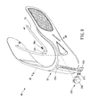
FIG. 5 is a breakdown stereogram of the preferred embodiment of the present invention;
FIG. 6 is an enlarged view of a positioning mechanism of the preferred embodiment of the present invention;
FIGS. 7 and 8 are partially-enlarged perspective views showing the preferred embodiment of the present invention in operation;
FIG. 9 is a breakdown view of another preferred embodiment of the present invention;
FIG. 10 is a drawing showing another preferred embodiment of the present invention from another perspective;
FIG. 11 is a perspective view showing a part of another preferred embodiment of the present invention; and
FIG. 12 is partially-enlarged view of FIG. 11.
DETAILED DESCRIPTION OF THE PREFERRED EMBODIMENTS
The present invention will be clearer from the following description when viewed together with the accompanying drawings, which show, for purpose of illustrations only, the preferred embodiment in accordance with the present invention.
Please refer to FIGS. 1 to 8 for a preferred embodiment of the present invention. An adjustable neck brace 1 includes a neck collar 2, a single positioning mechanism 3, a chin support 4 and at least one connecting member 5.
The neck collar 2 includes a sliding engaging groove 21, and the sliding engaging groove 21 extends in an extension direction and has a first engaging portion 22. The positioning mechanism 3 is attached to the neck collar 2 and movable along the sliding engaging groove 21, the positioning mechanism 3 has a second engaging portion 31, and the second engaging portion 31 is releasably positioningly engaged with the first engaging portion 22. The chin support 4 is relatively movably connected to the neck collar 2. The at least one connecting member 5 connects the positioning mechanism 3 and the chin support 4. Therefore, a user can operate the positioning mechanism 3 to adjust or position a position of the chin support 4 relative to the neck collar 2.
In this embodiment, the positioning mechanism 3 includes a mount portion 32 which is slidably arranged on the neck collar 2 and an operating member 33 which is connected to the mount portion 32, two of the connecting members 5 are connected to the mount portion 32, and the operating portion 33 has the second engaging portion 31. The neck collar 2 further includes two through slots 24 extending in the extension direction and located by two sides of the sliding engaging groove 21, the mount portion 32 includes two wing portions 321, a distal end of each said wing portion 321 is disposed through one of the through slots 24 so as to positioningly restrict the mount portion 32 in a movement range, and the distal end of each said wing portion 321 is connected to one of the connecting members 5 so as to adjust relative positions of the chin support 4 and the neck collar 2 synchronously through each said connecting member 5.
The mount portion 32 includes a base 322 having the two wing portions 321 and two blocking walls 324 connected to two sides of the base 322, the operating member 33 is disposed between the two blocking walls 324, preferably, the two blocking walls 324 are detachably connected to the base 322 so as to assemble/disassemble the positioning mechanism 3 conveniently, an elastic member 323 is disposed between the operating member 33 and the base 322, the elastic member 323 makes the second engaging portion 31 have a tendency to move toward the first engaging portion 22 normally so as to make sure that the second engaging portion 31 can be stably engaged with the first engaging portion 22.
In this embodiment, one of the first engaging portion 22 and the second engaging portion 31 includes at least one recess, and the other of the first engaging portion 22 and the second engaging portion 31 includes at least one protrusion. Specifically, the first engaging portion 22 includes a plurality of recesses 221 arranged along the extension direction in intervals, each said recess 221 has two sides each having a spacing wall 222, the second engaging portion 31 includes an engaging block 311 which is releasably positioningly engaged with one of the recesses 221, and the spacing wall 222 is provided for being positioningly engaged with the engaging block 311.
The neck collar 2 further has two guiding slots 23, the two guiding slots 23 are located by two sides of the sliding engaging groove 21 and extend tiltedly away from the sliding engaging groove 21, one of two end portions of each said connecting member 5 is slidably disposed within one of the guiding slots 23, and the other of the two end portions of each said connecting member 5 is pivoted to one of the wing portions 321 (when in use, an included angle between the wing portion 321 and the connecting member 5 changes, and in order to prevent the connecting member 5 and the wing portion 321 from being bent and damaged, the connecting member 5 and the wing portion 321 are pivoted to each other so that the included angle can be adjusted smoothly in accordance with different requirements). The neck collar 2 has an inner wall which is curved, and the two connecting members 5 are flexible and extend along the inner wall of the neck collar 2 so that when in operation, the connecting member 5 can slidably abut against the inner wall of the neck collar 2 to stabilize the operation. The two blocking walls 324 are opposite to the two spacing walls 222 of one of the recesses 221 and can positioningly restricting the operating member 33 therebetween.
When in use, the user can press and push the operating member 33 to adjust the chin support 4 to a proper position, and one of the two end portions of each said connecting member 5 pushes up or pulls down the chin support 4 along the two guiding slots 23; and when the user stops pressing the operating member 33, the chin support 4 can be relatively positioned.
Please refer to FIGS. 9 to 12 for another embodiment. The first engaging portion 22 b includes a plurality of recesses 221 b arranged along the extension direction in intervals, and the second engaging portion 31 b is releasably positioningly engaged with one of the recesses 221 b. The neck collar 2 b further includes a sliding seat 25 b corresponding to the sliding engaging groove 21 b. The positioning mechanism 3 b includes a mount portion 32 b which is movably arranged on the sliding seat 25 b and an operating member 33 b which is connected to the mount portion 32 b. The mount portion 32 b includes a mount body 35 b which is saddled on the sliding seat 25 b, a position-restricting block 34 b which is connected to the at least one connecting member 5 b and located by two opposite sides of the sliding engaging groove 21 b with the mount body 35 b (it is understandable that the at least one connecting member 5 b and the position-restricting block 34 b may be a structure which is integrally formed or not) and a pin 36 b which is disposed through the sliding engaging groove 21 b and connects the mount body 35 b and the position-restricting block 34 b (in other embodiments, the position-restricting block may has a sliding slot, and the pin may be slidably arranged within the sliding slot so that when the user operates the positioning mechanism, the mount body does not need to move horizontally with the pin synchronously, and the positioning mechanism can move smoothly), and the pin 36 b has the second engaging portion 31 b. The operating member 33 b is movably disposed through the mount body 35 b and the sliding seat 25 b and connected to the pin 36 b. An elastic member 37 b is disposed between the operating member 33 b and the mount body 35 b, and the elastic member 37 b makes the pin 36 b have a tendency to move toward the at least one recess 221 b normally. When in use, the user can press the operating member 33 b to make the pin 36 b detach from the at least one recess 221 b and adjust the adjustable neck brace 1 b through sliding the mount portion 32 b.
In other embodiments, the guiding slot may be arranged vertically; the recess of the first engaging portion may be arranged outwardly, the operating member of the positioning mechanism may be adjusted through pulling outward, and the second engaging portion of the operating member may have a tendency to move toward the first engaging portion normally; the positioning mechanism may be provided with the elastic member and fixedly engaged with the first and second engaging portions through latches.
Given the above, when using the adjustable neck brace, the user only needs to adjust the single positioning mechanism, and the chin support can be adjusted to a proper position through the at least one connecting member. In addition, the adjustable neck brace has a simple structure, and it is easy to be assembled and cost-saving to be manufactured.
While we have shown and described various embodiments in accordance with the present invention, it should be clear to those skilled in the art that further embodiments may be made without departing from the scope of the present invention.

Claims (9)

What is claimed is:
1. An adjustable neck brace, including:
a neck collar, including only one sliding engaging groove which is disposed at middle front of the neck collar, the only one sliding engaging groove extending in an extension direction and having a first engaging portion;
only one positioning member, attached to the neck collar and movable along the only one sliding engaging groove, having a second engaging portion, the second engaging portion being releasably positioningly engaged with the first engaging portion;
a chin support, relatively movably connected to the neck collar;
at least one connecting member, connecting the only one positioning member and the chin support wherein one of the first engaging portion and the second engaging portion includes at least one recess, and the other of the first engaging portion and the second engaging portion includes at least one protrusion, wherein the first engaging portion includes a plurality of recesses arranged along the extension direction in intervals, and the second engaging portion is releasably positioningly engaged with one of the recesses; the neck collar further includes a sliding seat corresponding to the only one sliding engaging groove; the only one positioning member includes a mount portion which is slidably arranged on the sliding seat and an operating member which is connected to the mount portion; the mount portion includes a mount body which is saddled on the sliding seat, a position-restricting block which is connected to the at least one connecting member and located by two opposite sides of the only one sliding engaging groove with the mount body and a pin which is disposed through the only one sliding engaging groove and connecting the mount body and the position-restricting block, and the pin has the second engaging portion; the operating member is movably disposed through the mount body and the sliding seat and connected to the pin; an elastic member is disposed between the operating member and the mount body, and the elastic member makes the pin have a tendency to move toward the at least one recess normally.
2. The adjustable neck brace of claim 1, wherein the first engaging portion includes a plurality of recesses arranged along the extension direction in intervals, and the second engaging portion includes an engaging block which is releasably positioningly engaged with one of the recesses.
3. The adjustable neck brace of claim 1, wherein the neck collar further has two guiding slots, the two guiding slots are located by two sides of the only one sliding engaging groove and extend tiltedly away from the only one sliding engaging groove, a number of the at least one connecting member is two, and one of two end portions of each said connecting member is slidably disposed within one of the guiding slots.
4. The adjustable neck brace of claim 3, wherein the two connecting members are flexible.
5. The adjustable neck brace of claim 1, wherein the only one positioning member includes a mount portion which is slidably arranged on the neck collar and an operating member which is connected to the mount portion, the at least one connecting member is connected to the mount portion, and an operating member has the second engaging portion.
6. The adjustable neck brace of claim 5, wherein the neck collar further includes two through slots extending in the extension direction and located by two sides of the only one sliding engaging groove, the mount portion includes two wing portions, a distal end of each said wing portion is disposed through one of the through slots, and the distal end of each said wing portion is connected to one of the connecting members.
7. The adjustable neck brace of claim 6, wherein the mount portion includes a base having the two wing portions and two blocking walls connected to two sides of the base, the operating member is disposed between the two blocking walls, an elastic member is disposed between the operating member and the base, and the elastic member makes the second engaging portion have a tendency to move toward the first engaging portion normally.
8. The adjustable neck brace of claim 7, wherein the two blocking walls are detachably connected to the base.
9. The adjustable neck brace of claim 8, wherein the first engaging portion includes a plurality of recesses arranged along the extension direction in intervals, each said recess has two sides each having a spacing wall, and the second engaging portion includes an engaging block which is releasably positioningly engaged with one of the recesses; the neck collar further has two guiding slots, the two guiding slots are located by the two sides of the only one sliding engaging groove and extend tiltedly away from the only one sliding engaging groove, a number of the at least one connecting member is two, one of the two end portions of each said connecting member is slidably disposed within one of the guiding slots, and the other of the two end portions of each said connecting member is pivoted to one of the wing portions; the neck collar has an inner wall which is curved, and the two connecting members are flexible and extend along the inner wall of the neck collar; the two blocking walls are opposite to the two spacing walls of one of the recesses and capable of positioningly restricting the operating member therebetween.
US15/198,335 2016-06-30 2016-06-30 Adjustable neck brace Active 2038-05-25 US10463524B2 (en)

Priority Applications (2)

Application Number Priority Date Filing Date Title
US15/198,335 US10463524B2 (en) 2016-06-30 2016-06-30 Adjustable neck brace
US16/558,644 US11207203B2 (en) 2016-06-30 2019-09-03 Adjustable neck brace

Applications Claiming Priority (1)

Application Number Priority Date Filing Date Title
US15/198,335 US10463524B2 (en) 2016-06-30 2016-06-30 Adjustable neck brace

Related Child Applications (1)

Application Number Title Priority Date Filing Date
US16/558,644 Division US11207203B2 (en) 2016-06-30 2019-09-03 Adjustable neck brace

Publications (2)

Publication Number Publication Date
US20180000625A1 US20180000625A1 (en) 2018-01-04
US10463524B2 true US10463524B2 (en) 2019-11-05

Family

ID=60806371

Family Applications (2)

Application Number Title Priority Date Filing Date
US15/198,335 Active 2038-05-25 US10463524B2 (en) 2016-06-30 2016-06-30 Adjustable neck brace
US16/558,644 Active 2037-05-13 US11207203B2 (en) 2016-06-30 2019-09-03 Adjustable neck brace

Family Applications After (1)

Application Number Title Priority Date Filing Date
US16/558,644 Active 2037-05-13 US11207203B2 (en) 2016-06-30 2019-09-03 Adjustable neck brace

Country Status (1)

Country Link
US (2) US10463524B2 (en)

Families Citing this family (4)

* Cited by examiner, † Cited by third party
Publication number Priority date Publication date Assignee Title
KR20180087908A (en) * 2017-01-25 2018-08-03 삼성디스플레이 주식회사 Display device
DE202018100997U1 (en) * 2018-02-22 2019-05-23 Thuasne Deutschland Gmbh Cervical orthosis with a U-shaped frame
CN114222548A (en) 2019-05-21 2022-03-22 Djo有限责任公司 Height, depth and circumferential adjusting mechanism of neck support
US12023270B2 (en) * 2022-01-27 2024-07-02 Yu-Chien WANG Cervical collar

Citations (8)

* Cited by examiner, † Cited by third party
Publication number Priority date Publication date Assignee Title
US20120130295A1 (en) * 2010-11-24 2012-05-24 Thomas Haider Universally adjustable cervical collar
US20120165712A1 (en) * 2010-12-20 2012-06-28 Salvatore Calabrese Cervical collar with independent height and circumference adjustability
US20130261519A1 (en) * 2012-04-02 2013-10-03 Geoffrey Garth Cervical Collar Spinal Height Adjustment System
US20130281900A1 (en) * 2012-04-20 2013-10-24 Daniel Suarez Cervical collar brace with cable adjustment
US20130310722A1 (en) * 2012-05-21 2013-11-21 Ossur Hf Cervical collar
US20150190266A1 (en) * 2014-01-03 2015-07-09 Megan Hollern Inflatable cervical collar
US20160008158A1 (en) * 2014-07-10 2016-01-14 Otto Bock Healthcare Lp Cervical collar with height adjustment mechanism
US20160058601A1 (en) * 2014-03-04 2016-03-03 Aspen Medical Partners, Llc Adjustable collar

Family Cites Families (1)

* Cited by examiner, † Cited by third party
Publication number Priority date Publication date Assignee Title
TWI373109B (en) * 2008-08-06 2012-09-21 Unimicron Technology Corp Package structure

Patent Citations (8)

* Cited by examiner, † Cited by third party
Publication number Priority date Publication date Assignee Title
US20120130295A1 (en) * 2010-11-24 2012-05-24 Thomas Haider Universally adjustable cervical collar
US20120165712A1 (en) * 2010-12-20 2012-06-28 Salvatore Calabrese Cervical collar with independent height and circumference adjustability
US20130261519A1 (en) * 2012-04-02 2013-10-03 Geoffrey Garth Cervical Collar Spinal Height Adjustment System
US20130281900A1 (en) * 2012-04-20 2013-10-24 Daniel Suarez Cervical collar brace with cable adjustment
US20130310722A1 (en) * 2012-05-21 2013-11-21 Ossur Hf Cervical collar
US20150190266A1 (en) * 2014-01-03 2015-07-09 Megan Hollern Inflatable cervical collar
US20160058601A1 (en) * 2014-03-04 2016-03-03 Aspen Medical Partners, Llc Adjustable collar
US20160008158A1 (en) * 2014-07-10 2016-01-14 Otto Bock Healthcare Lp Cervical collar with height adjustment mechanism

Also Published As

Publication number Publication date
US20180000625A1 (en) 2018-01-04
US20190388262A1 (en) 2019-12-26
US11207203B2 (en) 2021-12-28

Similar Documents

Publication Publication Date Title
US11207203B2 (en) Adjustable neck brace
US6966075B2 (en) Adjustable helmets
US8459746B2 (en) Adjustable armrest structure for a chair
ES2534048T3 (en) Adjustable child safety seat set
US20150250635A1 (en) Adjustable Collar
US20150114399A1 (en) Respiratory device comprising a fastening system
RU2553030C2 (en) Head support for surgical tables
EP3334326B1 (en) Adjustable locking surgical retractor
US9700139B2 (en) Armrest structure for a chair
US8303040B2 (en) Pillow support structure of a chair
US9179776B2 (en) Height adjustment mechanism for chair armrest and driving block thereof
US20160058601A1 (en) Adjustable collar
EP2177129A1 (en) Improved fastening device for furniture shelves
CN113226192A (en) Adjustable locking type surgical retractor
CN109310511B (en) Adjustable neck support
US20150100005A1 (en) Angle-adjustable rehabilitation device
CN103536996B (en) A kind of breathing mask forehead support frame and there is the breathing mask of this bracing frame
US20130213413A1 (en) Mouth mask
US20060200060A1 (en) Traction device with diaphragm and connection thereto
US9375590B2 (en) Respirator mask device
US9901698B2 (en) Respiratory mask
US20230233354A1 (en) Cervical collar
US9617078B2 (en) Conveyor frame assembly with cross supports
TWI792854B (en) Cervical collar
TWI810111B (en) Cervical collar

Legal Events

Date Code Title Description
STPP Information on status: patent application and granting procedure in general

Free format text: NON FINAL ACTION MAILED

STPP Information on status: patent application and granting procedure in general

Free format text: RESPONSE TO NON-FINAL OFFICE ACTION ENTERED AND FORWARDED TO EXAMINER

STPP Information on status: patent application and granting procedure in general

Free format text: NOTICE OF ALLOWANCE MAILED -- APPLICATION RECEIVED IN OFFICE OF PUBLICATIONS

STPP Information on status: patent application and granting procedure in general

Free format text: PUBLICATIONS -- ISSUE FEE PAYMENT VERIFIED

STCF Information on status: patent grant

Free format text: PATENTED CASE

MAFP Maintenance fee payment

Free format text: PAYMENT OF MAINTENANCE FEE, 4TH YR, SMALL ENTITY (ORIGINAL EVENT CODE: M2551); ENTITY STATUS OF PATENT OWNER: SMALL ENTITY

Year of fee payment: 4