US10463291B2 - Retractable blood collection devices and methods - Google Patents
Retractable blood collection devices and methods Download PDFInfo
- Publication number
- US10463291B2 US10463291B2 US15/559,745 US201615559745A US10463291B2 US 10463291 B2 US10463291 B2 US 10463291B2 US 201615559745 A US201615559745 A US 201615559745A US 10463291 B2 US10463291 B2 US 10463291B2
- Authority
- US
- United States
- Prior art keywords
- needle
- seal
- blood collection
- plunger
- retraction
- Prior art date
- Legal status (The legal status is an assumption and is not a legal conclusion. Google has not performed a legal analysis and makes no representation as to the accuracy of the status listed.)
- Expired - Fee Related, expires
Links
- 239000008280 blood Substances 0.000 title claims abstract description 245
- 210000004369 blood Anatomy 0.000 title claims abstract description 245
- 238000000034 method Methods 0.000 title description 6
- 239000003380 propellant Substances 0.000 claims abstract description 106
- 230000004913 activation Effects 0.000 claims abstract description 35
- 230000007246 mechanism Effects 0.000 claims abstract description 26
- 238000007789 sealing Methods 0.000 claims description 86
- 230000033001 locomotion Effects 0.000 claims description 46
- 230000004044 response Effects 0.000 claims description 13
- 238000003780 insertion Methods 0.000 claims description 9
- 230000037431 insertion Effects 0.000 claims description 9
- 230000017531 blood circulation Effects 0.000 claims description 6
- 230000000717 retained effect Effects 0.000 claims description 4
- 230000015572 biosynthetic process Effects 0.000 claims description 3
- 239000012530 fluid Substances 0.000 claims description 3
- 230000008878 coupling Effects 0.000 claims 1
- 238000010168 coupling process Methods 0.000 claims 1
- 238000005859 coupling reaction Methods 0.000 claims 1
- 239000000463 material Substances 0.000 description 13
- 230000036961 partial effect Effects 0.000 description 12
- 238000003825 pressing Methods 0.000 description 6
- 238000007493 shaping process Methods 0.000 description 6
- -1 StyroluxTM Polymers 0.000 description 5
- 239000000853 adhesive Substances 0.000 description 5
- 230000001070 adhesive effect Effects 0.000 description 5
- 208000012266 Needlestick injury Diseases 0.000 description 4
- 230000000295 complement effect Effects 0.000 description 4
- 238000004519 manufacturing process Methods 0.000 description 4
- 238000010276 construction Methods 0.000 description 3
- 229920001971 elastomer Polymers 0.000 description 3
- 239000000806 elastomer Substances 0.000 description 3
- 239000013536 elastomeric material Substances 0.000 description 3
- 230000008569 process Effects 0.000 description 3
- 230000001105 regulatory effect Effects 0.000 description 3
- 229920002725 thermoplastic elastomer Polymers 0.000 description 3
- IJGRMHOSHXDMSA-UHFFFAOYSA-N Atomic nitrogen Chemical compound N#N IJGRMHOSHXDMSA-UHFFFAOYSA-N 0.000 description 2
- 239000004743 Polypropylene Substances 0.000 description 2
- 230000003466 anti-cipated effect Effects 0.000 description 2
- 238000013461 design Methods 0.000 description 2
- 201000010099 disease Diseases 0.000 description 2
- 208000037265 diseases, disorders, signs and symptoms Diseases 0.000 description 2
- 238000001990 intravenous administration Methods 0.000 description 2
- 239000004417 polycarbonate Substances 0.000 description 2
- 229920000515 polycarbonate Polymers 0.000 description 2
- 229920001155 polypropylene Polymers 0.000 description 2
- 230000000284 resting effect Effects 0.000 description 2
- 239000007779 soft material Substances 0.000 description 2
- 238000012546 transfer Methods 0.000 description 2
- LVGUZGTVOIAKKC-UHFFFAOYSA-N 1,1,1,2-tetrafluoroethane Chemical compound FCC(F)(F)F LVGUZGTVOIAKKC-UHFFFAOYSA-N 0.000 description 1
- 208000012260 Accidental injury Diseases 0.000 description 1
- 208000035473 Communicable disease Diseases 0.000 description 1
- 208000027418 Wounds and injury Diseases 0.000 description 1
- 238000007792 addition Methods 0.000 description 1
- 230000004323 axial length Effects 0.000 description 1
- 230000008901 benefit Effects 0.000 description 1
- 210000001124 body fluid Anatomy 0.000 description 1
- 239000010839 body fluid Substances 0.000 description 1
- 238000005520 cutting process Methods 0.000 description 1
- 230000006378 damage Effects 0.000 description 1
- 238000003745 diagnosis Methods 0.000 description 1
- 239000003814 drug Substances 0.000 description 1
- 229940079593 drug Drugs 0.000 description 1
- 239000007789 gas Substances 0.000 description 1
- UKACHOXRXFQJFN-UHFFFAOYSA-N heptafluoropropane Chemical compound FC(F)C(F)(F)C(F)(F)F UKACHOXRXFQJFN-UHFFFAOYSA-N 0.000 description 1
- 238000002347 injection Methods 0.000 description 1
- 239000007924 injection Substances 0.000 description 1
- 208000014674 injury Diseases 0.000 description 1
- 230000001788 irregular Effects 0.000 description 1
- 230000000670 limiting effect Effects 0.000 description 1
- 239000007788 liquid Substances 0.000 description 1
- 238000012986 modification Methods 0.000 description 1
- 230000004048 modification Effects 0.000 description 1
- 238000012544 monitoring process Methods 0.000 description 1
- 229910052757 nitrogen Inorganic materials 0.000 description 1
- 239000004033 plastic Substances 0.000 description 1
- 229920000642 polymer Polymers 0.000 description 1
- 229920001296 polysiloxane Polymers 0.000 description 1
- 238000012545 processing Methods 0.000 description 1
- 230000001681 protective effect Effects 0.000 description 1
- 230000002829 reductive effect Effects 0.000 description 1
- 239000000758 substrate Substances 0.000 description 1
- 210000003462 vein Anatomy 0.000 description 1
- 238000003466 welding Methods 0.000 description 1
Images


Classifications
-
- A—HUMAN NECESSITIES
- A61—MEDICAL OR VETERINARY SCIENCE; HYGIENE
- A61B—DIAGNOSIS; SURGERY; IDENTIFICATION
- A61B5/00—Measuring for diagnostic purposes; Identification of persons
- A61B5/15—Devices for taking samples of blood
- A61B5/150007—Details
- A61B5/150374—Details of piercing elements or protective means for preventing accidental injuries by such piercing elements
- A61B5/150534—Design of protective means for piercing elements for preventing accidental needle sticks, e.g. shields, caps, protectors, axially extensible sleeves, pivotable protective sleeves
- A61B5/150572—Pierceable protectors, e.g. shields, caps, sleeves or films, e.g. for hygienic purposes
-
- A—HUMAN NECESSITIES
- A61—MEDICAL OR VETERINARY SCIENCE; HYGIENE
- A61B—DIAGNOSIS; SURGERY; IDENTIFICATION
- A61B5/00—Measuring for diagnostic purposes; Identification of persons
- A61B5/15—Devices for taking samples of blood
- A61B5/150007—Details
- A61B5/150015—Source of blood
- A61B5/15003—Source of blood for venous or arterial blood
-
- A—HUMAN NECESSITIES
- A61—MEDICAL OR VETERINARY SCIENCE; HYGIENE
- A61B—DIAGNOSIS; SURGERY; IDENTIFICATION
- A61B5/00—Measuring for diagnostic purposes; Identification of persons
- A61B5/15—Devices for taking samples of blood
- A61B5/150007—Details
- A61B5/150206—Construction or design features not otherwise provided for; manufacturing or production; packages; sterilisation of piercing element, piercing device or sampling device
- A61B5/150236—Pistons, i.e. cylindrical bodies that sit inside the syringe barrel, typically with an air tight seal, and slide in the barrel to create a vacuum or to expel blood
-
- A—HUMAN NECESSITIES
- A61—MEDICAL OR VETERINARY SCIENCE; HYGIENE
- A61B—DIAGNOSIS; SURGERY; IDENTIFICATION
- A61B5/00—Measuring for diagnostic purposes; Identification of persons
- A61B5/15—Devices for taking samples of blood
- A61B5/150007—Details
- A61B5/150206—Construction or design features not otherwise provided for; manufacturing or production; packages; sterilisation of piercing element, piercing device or sampling device
- A61B5/150259—Improved gripping, e.g. with high friction pattern or projections on the housing surface or an ergonometric shape
-
- A—HUMAN NECESSITIES
- A61—MEDICAL OR VETERINARY SCIENCE; HYGIENE
- A61B—DIAGNOSIS; SURGERY; IDENTIFICATION
- A61B5/00—Measuring for diagnostic purposes; Identification of persons
- A61B5/15—Devices for taking samples of blood
- A61B5/150007—Details
- A61B5/150343—Collection vessels for collecting blood samples from the skin surface, e.g. test tubes, cuvettes
-
- A—HUMAN NECESSITIES
- A61—MEDICAL OR VETERINARY SCIENCE; HYGIENE
- A61B—DIAGNOSIS; SURGERY; IDENTIFICATION
- A61B5/00—Measuring for diagnostic purposes; Identification of persons
- A61B5/15—Devices for taking samples of blood
- A61B5/150007—Details
- A61B5/150374—Details of piercing elements or protective means for preventing accidental injuries by such piercing elements
- A61B5/150381—Design of piercing elements
- A61B5/150389—Hollow piercing elements, e.g. canulas, needles, for piercing the skin
-
- A—HUMAN NECESSITIES
- A61—MEDICAL OR VETERINARY SCIENCE; HYGIENE
- A61B—DIAGNOSIS; SURGERY; IDENTIFICATION
- A61B5/00—Measuring for diagnostic purposes; Identification of persons
- A61B5/15—Devices for taking samples of blood
- A61B5/150007—Details
- A61B5/150374—Details of piercing elements or protective means for preventing accidental injuries by such piercing elements
- A61B5/150381—Design of piercing elements
- A61B5/150473—Double-ended needles, e.g. used with pre-evacuated sampling tubes
-
- A—HUMAN NECESSITIES
- A61—MEDICAL OR VETERINARY SCIENCE; HYGIENE
- A61B—DIAGNOSIS; SURGERY; IDENTIFICATION
- A61B5/00—Measuring for diagnostic purposes; Identification of persons
- A61B5/15—Devices for taking samples of blood
- A61B5/150007—Details
- A61B5/150374—Details of piercing elements or protective means for preventing accidental injuries by such piercing elements
- A61B5/150534—Design of protective means for piercing elements for preventing accidental needle sticks, e.g. shields, caps, protectors, axially extensible sleeves, pivotable protective sleeves
- A61B5/15058—Joining techniques used for protective means
- A61B5/150595—Joining techniques used for protective means by snap-lock (i.e. based on axial displacement)
-
- A—HUMAN NECESSITIES
- A61—MEDICAL OR VETERINARY SCIENCE; HYGIENE
- A61B—DIAGNOSIS; SURGERY; IDENTIFICATION
- A61B5/00—Measuring for diagnostic purposes; Identification of persons
- A61B5/15—Devices for taking samples of blood
- A61B5/150007—Details
- A61B5/150374—Details of piercing elements or protective means for preventing accidental injuries by such piercing elements
- A61B5/150534—Design of protective means for piercing elements for preventing accidental needle sticks, e.g. shields, caps, protectors, axially extensible sleeves, pivotable protective sleeves
- A61B5/150694—Procedure for removing protection means at the time of piercing
- A61B5/150709—Procedure for removing protection means at the time of piercing semi-automatically removed, i.e. before puncturing the protection is removed by a mechanism initiated by a deliberate action by the user, such as pressing a button
-
- A—HUMAN NECESSITIES
- A61—MEDICAL OR VETERINARY SCIENCE; HYGIENE
- A61B—DIAGNOSIS; SURGERY; IDENTIFICATION
- A61B5/00—Measuring for diagnostic purposes; Identification of persons
- A61B5/15—Devices for taking samples of blood
- A61B5/150007—Details
- A61B5/150374—Details of piercing elements or protective means for preventing accidental injuries by such piercing elements
- A61B5/150534—Design of protective means for piercing elements for preventing accidental needle sticks, e.g. shields, caps, protectors, axially extensible sleeves, pivotable protective sleeves
- A61B5/150694—Procedure for removing protection means at the time of piercing
- A61B5/150717—Procedure for removing protection means at the time of piercing manually removed
-
- A—HUMAN NECESSITIES
- A61—MEDICAL OR VETERINARY SCIENCE; HYGIENE
- A61B—DIAGNOSIS; SURGERY; IDENTIFICATION
- A61B5/00—Measuring for diagnostic purposes; Identification of persons
- A61B5/15—Devices for taking samples of blood
- A61B5/150007—Details
- A61B5/150732—Needle holders, for instance for holding the needle by the hub, used for example with double-ended needle and pre-evacuated tube
-
- A—HUMAN NECESSITIES
- A61—MEDICAL OR VETERINARY SCIENCE; HYGIENE
- A61B—DIAGNOSIS; SURGERY; IDENTIFICATION
- A61B5/00—Measuring for diagnostic purposes; Identification of persons
- A61B5/15—Devices for taking samples of blood
- A61B5/153—Devices specially adapted for taking samples of venous or arterial blood, e.g. with syringes
Definitions
- Some embodiments of the present invention pertain to blood collection devices having a retractable sharps element. Some embodiments of the present invention pertain to blood collection devices for use with conventional blood collection vials, the device having a retractable sharps element.
- Blood must be collected from individuals for many reasons, for example for diagnosis or monitoring of a medical condition, administration of certain drugs, or removal of blood for a specific reason.
- a significant number of needlestick injuries occur during the handling of blood collection devices. Some of these injuries may occur during use of the blood collection device, and some may occur after the device has been used but before the needle of the device has been rendered innocuous, for example by capping the needle.
- a blood collection device for use with a blood collection vial, the blood collection device comprising a housing having a proximal end configured to receive the blood collection vial, a needle retraction assembly positioned near a distal end of the housing and moveable between an initial assembled configuration and an activated configuration in response to the application of an activation force against the blood collection vial by a user, the needle retraction assembly having a spike plate having rupturing members extending distally of the needle retraction assembly and a needle hub engaged with other components of the needle retraction assembly in a first position where the needle retraction assembly is in the initial assembled configuration, and moveable to a second, sealed, position within the needle retraction assembly in response to the application of the activation force to move the needle retraction assembly to the activated configuration.
- a needle is supported by the needle hub, the needle having a distal end for piercing the skin of a subject and a proximal end for insertion through a cover of the blood collection vial.
- a propellant chamber is located distally of the spike plate, the propellant chamber having a seal for initially containing propellant, the seal being rupturable upon movement of the spike plate to the activated position to release the propellant, so that release of the propellant moves the needle retraction assembly and the needle in the proximal direction to retract the needle inside the housing.
- a blood collection device having a housing, a plunger slideably mounted within the housing, sidewalls of the plunger defining a retraction lumen within the plunger.
- a needle seal is frictionally engaged with the retraction lumen at a distal end of the plunger, the needle seal having a sealing engagement structure on a distal side thereof.
- a needle is initially secured at a distal portion of the housing, and a needle support structure is frictionally engaged in the distal portion of the housing for initially securing the needle in place, a first portion of the needle support structure being moveable in a distal direction in response to application of an activation force against the plunger by a user, a second portion of the needle support structure being shaped and configured to engage with the sealing engagement structure of the needle seal upon the application of the activation force against the plunger by the user to provide a needle retraction assembly including the needle.
- a propellant chamber is positioned in the housing distally of the needle support structure.
- Rupturing spikes are provided proximally of the propellant chamber and distally of the needle support structure, the rupturing spikes being moveable to rupture the propellant chamber upon the application of the activation force against the plunger by the user.
- a blood collection outlet is provided for passing blood flowing through the needle to a blood collection reservoir, and a blood flow path is provided through the needle and past the plunger to the blood collection outlet when the blood collection device is in its initial configuration.
- the application of the activation force against the plunger by the user moves the plunger distally within the housing to engage the needle seal with the second portion of the needle support structure to form the needle retraction assembly, and causes the first portion of the needle support structure to move distally within the housing to cause the rupturing spikes to release propellant from the propellant chamber, so that the released propellant retracts the needle retraction assembly and the needle within the retraction lumen.
- FIG. 1 is a cross-sectional view of an example embodiment of a retractable blood collection device, with a conventional blood collection vial partially inserted thereon.
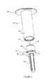
- FIG. 2 is a perspective view of an example embodiment of a retractable blood collection device, with the needle assembly separated from the main body of the device.
- FIG. 3 is a cross-sectional view of the example embodiment of FIG. 2 .
- FIG. 4 shows an enlarged partial cross sectional view of the example embodiment of FIG. 2 .
- FIG. 5 shows a cross-sectional view of the needle assembly of the example embodiment of FIG. 2 .
- FIG. 6 shows a cross-sectional view of the example embodiment of FIG. 2 , with a blood collection vial inserted thereon in its initial assembled position.
- FIG. 7 shows an enlarged partial cross-sectional view of the example embodiment of FIG. 6 .
- FIG. 8 shows a further enlarged partial cross-sectional view of the example embodiment of FIG. 6 .
- FIG. 9 shows an enlarged partial cross-sectional view of the example embodiment of FIG. 6 , but with the blood collection vial moved to the activated position.
- FIG. 10 shows a cross-sectional view of the example embodiment of FIG. 6 , with the needle in its final retracted position.
- FIG. 11 shows an enlarged partial cross-sectional view of the example embodiment of FIG. 6 , with the needle in its final retracted position.
- FIG. 12 shows a perspective view of a second example embodiment of a retractable blood collection device, with the needle removed.
- FIG. 13A shows a cross-sectional view of the example embodiment of FIG. 12 , with the needle in its initial assembled position.
- FIG. 13B shows a cross-sectional view of a second example embodiment of a retractable blood collection device that is generally similar to the embodiment of FIG. 12 .
- FIG. 14 shows an exploded view of components of the needle support structure and the needle seal in the example embodiment of FIG. 13B .
- FIG. 15 shows a trimetric cross-sectional view of the example embodiment of Figure 12 , with the seal of the propellant chamber removed for clarity.
- FIG. 16 shows a cross-sectional view of the example embodiment of FIG. 12 at the first activation step.
- FIG. 17 shows a partial enlarged cross-sectional view of components of the needle retraction assembly of the example embodiment of FIG. 12 at the first activation step.
- FIG. 18A shows a partial enlarged cross-sectional view of the components of the needle retraction assembly of the embodiment illustrated in FIG. 13B in their separated configuration
- FIG. 18B shows a partial enlarged cross-sectional view of these components in their engaged configuration.
- FIG. 19 shows a cross-sectional view of the example embodiment of FIG. 12 at the second activation step.
- FIG. 20 shows a partial enlarged cross-sectional view of components of the needle retraction assembly of the example embodiment of FIG. 12 at the second activation step.
- FIG. 21 shows a cross-sectional view of the example embodiment of FIG. 12 with the needle retracted.
- FIG. 22 shows a partial enlarged cross-sectional view of the example embodiment of FIG. 13B that includes a vent hole in the plunger to vent excess propellant to the atmosphere after needle retraction is complete.
- FIG. 23A is a side view of a further example embodiment of a blood collection device, and FIG. 23B is a side view thereof rotated by 90°.
- FIG. 24 is a sectional view of the embodiment illustrated in FIGS. 23A and 23B , with the device in an initial, unactivated configuration, ready to draw blood from a subject, in which the wings are not visible.
- FIG. 25 is an enlarged partial sectional view of the embodiment shown in FIG. 24 in the initial, unactivated configuration, in which the wings are not visible.
- FIG. 26 is a sectional view of the embodiment illustrated in FIG. 24 , after a user has initiated activation of the needle retraction mechanism, in which the wings are not visible.
- FIG. 27 is an enlarged partial sectional view of the embodiment illustrated in FIG. 26 after a user has initiated the retraction mechanism, in which the wings are not visible.
- FIG. 28 is a sectional view of the embodiment illustrated in FIGS. 23A-27 after the needle has been retracted.
- FIG. 29 is a side view showing the embodiment illustrated in FIGS. 23A-28 after the needle has been retracted.
- distal means in a direction away from a user's hand, having regard to the orientation in which the blood collection device is intended to be used.
- proximal means the opposite of distal, i.e. in a direction toward a user's hand.
- outwardly means in a radial direction away from the axial centerline of the blood collection device.
- inwardly means the opposite of outwardly, i.e. in a radial direction towards the axial centerline of the blood collection device.
- FIG. 1 an example embodiment of a retractable blood collection device 20 that can be used with a conventional blood collection vial 22 (for example, a VacutainerTM blood collection vial that is provided with a slight vacuum to assist in drawing blood into the vial) is illustrated.
- Blood collection device 20 has a main body 24 that is engageable with a needle assembly 26 that supports a cannula or needle 28 .
- main body 24 and needle assembly 26 could be provided as a single housing, rather than as two separate components.
- needle 28 is a double-ended needle, i.e. having two sharp ends, to facilitate both piercing the skin of a subject with the distal end of needle 28 , and piercing a cap of blood collection vial 22 as described below.
- needle 28 is sharp, and the proximal end of needle 28 is configured to be engaged by a small aperture 94 provided on the blood collection vial 22 , and to be covered by a moveable sheath to regulate the flow of blood through needle 28 as described below.
- the distal end of needle 28 is provided with a low angle bevel on its distal edge, to aid insertion of needle 28 into a vein.
- Cap 30 ( FIGS. 2 and 3 ) is provided to cover needle 28 prior to use of retractable blood collection device 20 .
- Cap 30 can be laminated, cemented, snapped, press fit, or otherwise suitably affixed to needle assembly 26 so that it can be removed when retractable blood collection device 20 is ready for use.
- needle assembly 26 has an external threaded surface 32 ( FIG. 2 ) that is engageable with a complementary threaded internal surface 34 provided in the distal end of main body 24 .
- a radially outwardly extending distal flange 36 provided on needle assembly 26 may facilitate a user inserting needle 28 into a subject from whom blood is to be drawn, and also in gripping needle assembly 26 and affixing it to main body 24 by rotating the two components so that threaded surfaces 32 , 34 are engaged when retractable blood collection device 20 is manufactured.
- a radially outwardly extending proximal flange 38 provided at the proximal end of main body 24 facilitates handling of retractable blood collection device 20 and insertion of a blood collection vial 22 thereon.
- flanges 36 and/or 38 are omitted.
- needle assembly 26 is laminated, cemented, snapped, press fit, ultrasonically welded, or otherwise suitably affixed to main body 24 in some other manner during manufacture to provide a single unit.
- flanges 36 are omitted.
- a suitable adhesive is applied over threaded surfaces 32 and/or 34 , so that after these threaded surfaces have been engaged, the needle assembly 26 cannot thereafter be removed from the main body 24 .
- Needle assembly 26 contains a needle retraction assembly 29 for retracting the needle 28 .
- the needle retraction assembly comprises a spike plate ring 54 , a retraction seal 70 , a retaining ring 52 , and a needle hub 40 . Each of these components is described in greater detail below.
- Needle 28 is supported in its initial position relative to needle retraction assembly 29 by a needle hub 40 . Needle 28 is crimped in, cemented to or otherwise securely fixed to needle hub 40 . In some embodiments, needle 28 is insert molded with needle hub 40 to create a single part.
- Needle hub 40 is moveable relative to the other components of needle retraction assembly 29 between a first sealed position when needle retraction assembly 29 is in its initial assembled position (e.g. as shown in FIG. 4 ), and a second sealed position when needle retraction assembly 29 is in its activated position (e.g. as shown in FIG. 9 ).
- needle hub 40 is provided with a first radial sealing feature 42 and a second radial sealing feature 44 .
- First radial sealing feature 42 is initially engaged within a retaining recess 46 formed between two radially inwardly extending arms 48 , 50 of a retaining ring 52 of needle retraction assembly 29 .
- Both first radial sealing feature 42 and second radial sealing feature 44 are configured to be sealingly engageable within retaining recess 46 , as described in greater detail below.
- needle hub 40 is moveable relative to the other components of needle retraction assembly 29 between a first position in which the first radial sealing feature is engaged with another component of retraction assembly 29 (the initial assembled position) and a second, sealed, position in which the second radial sealing feature is sealingly engaged with another component of retraction assembly 29 (the activated position).
- first and second radial sealing features 42 and 44 have been described as being substantially the same, these features need not be the same. Further, it is not essential that first radial sealing feature 42 be sealingly engaged with retaining recess 46 in the initial assembled position. At the times that first radial sealing feature 42 is engaged with retaining recess 46 (i.e. in the initial assembled position), all that is required is that the first radial sealing feature 42 prevent movement of needle hub 40 (and thus needle 28 ) relative to the other components of needle retraction assembly 29 , for example while needle 29 is being inserted into and/or withdrawn from a subject and while blood is being drawn.
- first radial sealing feature 42 should provide a sealing engagement with retaining ring 52 as needle hub 40 is moved proximally relative to the other components of needle retraction assembly 29 (including retaining ring 52 ).
- first radial sealing feature 42 is sealingly engaged with retaining recess 46 in the initial assembled position, and together with second radial sealing feature 44 provides a substantially continuous sealing engagement between needle hub 40 and retaining ring 52 as needle retraction assembly 29 moves from its initial assembled position to its activated position.
- retaining ring 52 is supported by a spike plate ring 54 .
- Spike plate ring 54 is generally cylindrical in shape, and has an upper flange 56 and a lower flange 58 connected by a central ring 60 extending therebetween. Retaining ring 52 is seated inside central ring 60 and does not move relative to central ring 60 during use or retraction of retractable blood collection device 20 .
- spike plate ring 54 is made of a relatively rigid material, for example a relatively rigid polymer such as polycarbonate, StyroluxTM, polypropylene, or the like, and retaining ring 52 is formed from a relatively more flexible material, such as an elastomer such as a thermoplastic elastomer.
- the material used to form retaining ring 52 should be sufficiently flexible to allow first radial sealing feature 42 to be displaced therefrom and second radial sealing feature 44 to be inserted therein during retraction of needle 28 , as described below, but should also have sufficient rigidity to hold needle hub 40 in place during normal use, for example during insertion of needle 28 into a subject.
- retaining ring 52 is provided as an overmold on spike plate 54 .
- spike plate ring 54 and retaining ring 52 can be provided as two separate components coupled together in any suitable manner, for example by a sufficiently tight friction fit, through the use of suitable adhesives, by provision of mechanical interlocks, or the like.
- a propellant chamber 62 is provided within needle assembly 26 .
- propellant chamber 62 is provided distally of spike plate ring 54 , and is formed as a generally cylindrical channel 64 formed within the body of needle assembly 26 and covered by a seal 66 .
- a compressed propellant is contained within propellant chamber 62 by seal 66 .
- Any suitable propellant can be used, for example a medical grade propellant such as a hydrofluorocarbon such as heptafluoropropane or 1,1,1,2-tetrafluoroethane, or medical grade nitrogen.
- spike plate ring 54 is provided with one or more spikes 68 , which rupture seal 66 when retraction of needle 28 is initiated by a user as described below.
- a retraction seal 70 is provided that is frictionally initially engaged with the sidewall 72 of the upper chamber 74 of needle assembly 26 .
- Retraction seal 70 is slideable in the distal direction within upper chamber 74 in response to the application of an activation force by a user.
- retraction seal 70 has a pair of outwardly extending O-ring seals 76 integrally formed therewith. O-ring seals 76 make sealing engagement with the inside surfaces of sidewall 72 . Provision of a pair of O-ring seals 76 spaced apart in the axial direction on retraction seal 70 helps to ensure that retraction seal 70 slides evenly and smoothly within upper chamber 74 .
- Retraction seal 70 is associated with spike plate ring 54 as part of the needle retraction assembly 29 .
- retraction seal 70 is seated inside of spike plate ring 54 , being axially retained between upper flange 56 and lower flange 58 of spike plate ring 54 .
- distal movement of spike plate ring 54 caused by the application of an activation force by a user causes retraction seal 70 (and thus needle retraction assembly 29 ) to slide distally within upper chamber 74 , advancing spikes 68 towards seal 66 .
- any suitable configuration that allows retraction seal and spike plate ring 54 to be moved distally to rupture seal 66 and proximally to retract needle 28 could be used.
- Retraction seal 70 can be made from any suitable material, for example silicone or an elastomer such as a thermoplastic elastomer. In some embodiments, retraction seal 70 is formed as an overmold on spike plate ring 54 . In some embodiments, retraction seal 70 is formed as a separate component from spike plate ring 54 , and is coupled to spike plate ring 54 in any suitable manner, for example by cutting axially through one portion of retraction seal 70 so that retraction seal 70 can be inserted over central ring 60 , by forming retraction seal 70 as a ring and forming spike plate ring 54 as two separate pieces (e.g.
- inset gap 78 there is a slight inset gap 78 between the radially outer edge of lower flange 58 and the inside surface of sidewall 72 and a similar inset gap 79 (best seen in FIG. 8 ) between the radially outer edge of upper flange 56 and the inside surface of sidewall 72 .
- the inset gaps do not need to be as large as that illustrated for inset gap 78 , although they can be that large or larger.
- the inset gaps 78 , 79 should be sufficiently large that upper and lower flanges 56 , 58 will not impinge on a radially inwardly extending projection 82 provided on the upper edge of sidewall 72 when spike plate ring 54 moves in the proximal direction during retraction of needle 28 .
- Projection 82 is a radially inwardly extending projection provided on the inside surface of sidewall 72 to prevent retraction seal 70 (and therefore the other components of needle retraction assembly 29 , as well as needle 28 ) from moving in the proximal direction during normal use of retractable blood collection device 20 .
- projection 82 is configured to allow retraction seal 70 to slide past projection 82 in the proximal direction under the force applied by released propellant when the retraction mechanism of device 20 is actuated.
- projection 82 comprises one or more discrete projections formed in the inside surface of sidewall 72 .
- projection 82 comprises a generally circular projection that extends continuously or substantially continuously around the inner diameter of sidewall 72 .
- projection 82 is not critical, so long as it initially retains needle retraction assembly 29 in place during normal use of retractable blood collection device 20 to collect blood, but allows needle retraction assembly 29 to slide past in the proximal direction after the retraction mechanism has been actuated by a user.
- upper chamber 74 of needle assembly 26 is generally cylindrical in shape, and retraction seal 70 and spike plate ring 54 similarly have a generally cylindrical shape. Because blood collection vials and blood collection devices have a generally cylindrical configuration, a corresponding cylindrical shape of components of blood collection device 20 is typical. However, nothing prevents the use of other shapes of components (e.g. having a triangular, square, or irregular cross-section across an axial length thereof), so long as such changes in shape do not affect the ability of the components to move relative to one another to achieve retraction of needle 28 as described herein.
- a distal needle seal 80 is provided to seal around needle 28 at the distal end of upper chamber 74 .
- distal needle seal 80 is secured within a central region 81 of the body of needle assembly 26 that is provided axially inwardly of generally cylindrical channel 64 .
- Distal needle seal 80 is made from a soft material to sealingly engage around the outside surface of needle 28 and prevent the flow of propellant past needle 28 and out of the propellant release chamber 88 .
- a proximal needle seal 84 is provided to cover the proximal end of needle 28 .
- the portion of proximal needle seal 84 that covers the proximal end of needle 28 has a small aperture therethrough, indicated by 86 , that allows proximal needle seal 84 to open around the proximal end of needle 28 when a blood collection vial 22 is inserted on retractable blood collection device 20 .
- Proximal needle seal 84 thus acts as a sheath, to cover the proximal end of needle 28 to prevent the flow of blood therethrough when a blood collection vial 22 is not inserted on retractable blood collection device 20 , but to allow blood to flow therethrough when a blood collection vial 22 is in use. This feature is useful where more than one vial of blood is to be collected from a patient.
- proximal needle seal 84 will prevent the flow of blood through needle 28 until a blood collection vial 22 is inserted inside main body 24 of retractable blood collection device 20 .
- Blood collection vial 22 has a tube 90 for receiving and containing blood, and a cover 92 for retaining blood within tube 90 .
- Cover 92 has a central portion made from a flexible material that has a small aperture 94 therethrough.
- Cover 92 is configured so that aperture 94 can be inserted over the proximal end of needle 28 , thereby displacing proximal needle seal 84 from the proximal end of needle 28 , as shown in FIGS. 6 and 7 .
- Aperture 94 is sufficiently small that a drop of liquid (e.g. blood) cannot pass therethrough when aperture 94 is not expanded around needle 28 . Thus, blood is securely retained within tube 90 once it has been obtained.
- liquid e.g. blood
- Blood collection vial 22 can be inserted within main body 24 of retractable blood collection device 20 from the proximal end until it reaches an initial assembled position immediately adjacent upper flange 56 of spike plate ring 54 .
- a user will feel resistance to further movement of blood collection vial 22 in the distal direction because of the engagement of retaining ring 52 with first radial sealing feature 42 of needle hub 40 (needle hub 40 being prevented from moving in the distal direction by reason of the contact of its distal end with central region 81 , optionally via distal needle seal 80 ) as well as because of the frictional engagement of O-ring seals 76 of retraction seal 70 with the inside of sidewall 72 . A user will thus know that blood collection vial 22 has reached its initial assembled position.
- vial 22 Once vial 22 has been filled with blood, a user can optionally withdraw vial 22 from retractable blood collection device 22 . Removal of cover 92 from the proximal end of needle 28 will result in proximal needle seal 84 moving in the proximal direction and once again covering the proximal opening of needle 28 , so that blood will not flow therethrough while no vial 22 is attached. A user can then insert a fresh vial 22 onto retractable blood collection device 22 , and can fill that vial 22 with blood. This process can be repeated any desired number of times, depending on the number of vials of blood that need to be collected from a given subject.
- the user can actuate the retraction mechanism to retract needle 28 within main body 24 to eliminate the sharps hazard posed by needle 28 .
- the retraction mechanism can be actuated while needle 28 remains in the subject.
- needle 28 is removed from the subject, and then a user actuates the retraction mechanism to retract needle 28 .
- FIG. 9 illustrates how the retraction mechanism is actuated.
- a user presses vial 22 in the distal direction beyond its initial assembled position, optionally using proximal flange 38 and/or distal flange 36 to assist in this process. Because the distal end of needle hub 40 is in contact with central region 81 (including optionally being in contact with distal needle seal 80 ), needle hub 40 cannot move in the distal direction in response to the applied force. However, the other components of the retraction assembly 29 are moved in the distal direction by this force. Retraction seal 70 is slideable within sidewall 72 in response to the applied force.
- Retaining ring 52 is made of a somewhat flexible material, and thus radially inwardly extending arm 50 can flex as it moves past second radial securing feature 44 , and radially inwardly extending arm 48 can likewise flex as it moves past first radial securing feature 42 .
- the components of needle retraction assembly 29 other than needle hub 40 i.e. retaining ring 52 , spike plate ring 54 , and retraction seal 70 ) are thus caused to move in the distal direction within propellant release chamber 88 when a user applies sufficient force to actuate the retraction mechanism.
- retractable blood collection device 20 should be designed so that the additional force required to actuate the retraction mechanism (i.e. to move vial 22 in the distal direction beyond its initial assembled position) is not unduly large, or users will have a difficult time actuating the retraction mechanism.
- the force required to actuate the retraction mechanism should be designed to be sufficiently large that it is unlikely that a user will inadvertently cause actuation of the retraction mechanism during ordinary use of retractable blood collection device 20 .
- Factors such as the hardness (e.g.
- durometer durometer of the material used to manufacture retaining ring 52 or retraction seal 70 and the shaping and configuration of radially inwardly extending arms 48 , 50 and/or first and second radial sealing features 42 , 44 can all influence the amount of force that will be required to actuate the retraction mechanism of device 20 .
- needle hub 40 and retaining ring 52 are such that a seal between needle hub 40 and retaining recess 46 is formed before seal 66 is ruptured, even if needle hub 40 and retaining ring 52 have not been moved fully to the activated position. This prevents the escape of propellant past needle hub 40 , which might result in a failure of the needle retraction assembly 29 to retract.
- a seal is formed between second radial sealing feature 44 and retaining ring 52 so that these two components are continuously sealed even during relative movement of these components, which prevents passage of propellant past needle hub 40 even if seal 66 is ruptured before radial sealing feature 44 is fully seated in retaining recess 46 .
- continuously sealed it is not meant that the location of the seal is substantially continuous, but rather that temporally as needle hub 40 moves relative to retaining ring 52 , there is a seal at some location between these two elements at all times from a first time before seal 66 is reasonably likely to be ruptured to a second time when radial sealing feature 44 becomes fully seated in retaining recess 46 .
- a distal axially extending flange 96 is provided at the distal end of spike plate ring 54 .
- Flange 96 contacts the proximal end of central region 81 and/or distal needle seal 80 , which ensures that at least a small gap 98 remains between lower flange 58 and the outside lip 95 of propellant chamber 62 , so that no seal is formed between lower flange 58 and the outside lip 95 of propellant chamber 62 .
- flange 96 is substantially circular, so that flange 96 forms a seal with the proximal end of central region 81 (and/or distal needle seal 80 , depending on the relative positioning of needle seal 80 ). Formation of a seal between flange 96 and central region 81 as aforesaid can minimize the amount of pressure applied by released propellant against needle hub 40 . This provides a safeguard or additional level of sealing in the event that seal 66 is ruptured before second radial sealing feature 44 has been fully engaged within retaining recess 46 , and also helps to ensure that second radial sealing feature 44 will be fully seated in retaining recess 46 as the needle retraction assembly 29 moves in the proximal direction. Accordingly, the sealing engagement between flange 96 and the proximal end of central region 81 provides a feature that is used in some embodiments to minimize the risk that needle 28 will not reliably retract.
- the released propellant applies a force in the proximal direction against retraction seal 70 to retract needle retraction assembly 29 and needle 28 .
- Spike plate ring 54 , retaining ring 52 , needle hub 40 , and blood collection vial 22 are all moved in the proximal direction by movement of retraction seal 70 .
- inset gaps 78 , 79 are sufficiently large to ensure that upper flange 56 and lower flange 58 pass by radially inwardly extending projection 82 when spike plate ring 54 moves in the proximal direction.
- the material used to provide retraction seal 70 is selected to be sufficiently flexible to allow O-ring seals 76 to pass by radially inwardly extending projection 82 when retraction seal 70 is moved in the proximal direction by the force of released propellant.
- the material used for retraction seal 70 should also be selected to provide a sufficient degree of resistance to passage over radially inwardly extending projection 82 such that forces experienced during normal use of retractable blood collection device 20 to collect blood (including insertion of needle 28 into a subject from whom blood is to be drawn) do not force retraction seal 70 past radially inwardly extending projection 82 .
- retraction seal 70 might experience approximately 1-2 lbs of force in the proximal direction during insertion of a needle 28 into a subject, and retraction seal 70 is designed not to move past radially inwardly extending projection 82 until a force in the proximal direction of at least 3-4 lbs is applied.
- the force expected to be applied against retraction seal 70 by released propellant is anticipated to be on the order of 9-10 lbs or more, so that retraction seal 70 will be reliably retracted past radially inwardly extending projection 82 upon actuation of the retraction mechanism.
- a pair of complementary angled sealing surfaces 100 , 102 are provided at the proximal end of needle assembly 26 and the distal portion of main body 24 , respectively.
- the engagement of threaded surfaces 32 , 34 forces angled sealing surfaces 100 , 102 tightly together, to help prevent the escape of propellant past the junction between needle assembly 26 and main body 24 .
- the engagement between needle assembly 26 and main body 24 is sufficiently airtight that angled sealing surfaces 100 , 102 are omitted.
- needle assembly 26 and main body 24 are integrally formed or permanently coupled together, e.g. by being laminated, cemented, snapped, press fit, ultrasonically welded, or otherwise joined, the engagement between the two components is airtight or substantially airtight, and angled sealing surfaces 100 , 102 can be omitted.
- retraction seal 70 slides proximally over radially inwardly extending projection 82 , it continues moving in the proximal direction.
- main body 24 To assist in stopping movement of retraction seal 70 (and therefore all of the other components of needle retraction assembly 29 sliding proximally under influence of released propellant) once needle 28 has been retracted to a desired degree (i.e. moved to its final retracted position) as shown in FIG. 10 , two features are provided on main body 24 . The first of these features is vent 104 provided in a sidewall of main body 24 at an axial location just distal of the final retracted position of retraction seal 70 .
- Vent 104 releases propellant from the interior of retractable blood collection device 20 , so that the proximal biasing pressure applied by released propellant is dissipated after retraction seal 70 slides proximally past vent 104 .
- vent 104 is omitted, and only a stop 106 (described below) is used to stop the proximal movement of retraction seal 70 .
- use of vent 104 helps to ensure that no compressed propellant remains within retractable blood collection device 20 , meaning that there is no ongoing hazard of a potential release of pressure from device 20 at some undesired future time or in some undesired manner that may cause needle 28 to become exposed.
- stop 106 is a radially inwardly extending projection that extends radially inwardly to a sufficient extent to stop further proximal movement of upper flange 56 of spike plate ring 54 past it at the point of contact.
- any structure that can make contact with some portion of the needle retraction assembly 29 , including spike plate ring 54 , retraction seal 70 , needle hub 40 or retaining ring 52 , to stop movement of these components past a predetermined point while still allowing blood collection vial 22 to pass could be used to provide the second feature that assists in stopping movement of retraction seal 70 .
- stop 106 could be omitted, and vent 104 alone could be used to stop movement of the retracting components once needle 28 has been retracted to the desired extent.
- vial 22 is removed by pulling in the proximal direction after needle 28 has been retracted, and stop 106 also acts to prevent unintended withdrawal of retraction seal 70 or any of the components associated therewith, including needle 28 , from main body 24 .
- stop 106 helps to prevent unintended withdrawal of needle 28 from main body 24 .
- needle 28 and blood collection vial 22 have been moved to the final retracted position, a user can pull on blood collection vial 22 in the proximal direction to remove the final vial of blood from blood collection device 20 .
- Needle 28 remains safely housed within main body 24 and needle assembly 26 , and the used retractable blood collection device 20 can be disposed of in accordance with applicable practices or regulations.
- first and/or second radial sealing features 42 , 44 that provide a sealing engagement with retaining recess 46 comprise an O-ring seal 108 A, 108 B, respectively, and two tapered seals 110 A, 110 B and 112 A, 112 B, respectively.
- O-ring seals 108 A, 108 B and tapered seals 110 A, 110 B, 112 A and 112 B are generally cylindrical in shape, and are sealingly engageable with retaining recess 46 , which is also generally cylindrical in shape in the illustrated embodiment.
- Tapered seals 110 A/ 110 B are engageable with a correspondingly angled surface provided on radially inwardly extending arm 48
- tapered seals 112 A/ 112 B are engageable with a correspondingly angled surface provided on radially inwardly extending arm 50 .
- first and second radial sealing features 42 , 44 have been described herein as having a particular configuration, any suitable type of sealing engagement that can be axially displaced to allow the first sealing feature to be released from retaining ring 52 and then allow a seal to be formed by the second sealing feature, while providing a substantially continuous sealing engagement before seal 66 is likely to be ruptured, even during sliding motion of needle hub 40 relative to retaining ring 52 , can be used.
- the structural features of both first and second radial sealing features 42 , 44 are the same.
- first and second radial sealing features 42 , 44 are different, but provide for sealing engagement with retaining recess 46 as the second radial sealing feature 44 becomes engaged within retaining recess 46 and once the second radial sealing feature 44 has reached its activated position (i.e. has been engaged within retaining recess 46 ).
- substantially continuous sealing between needle hub 40 and retaining ring 52 is maintained as follows. As second radial sealing feature 44 moves past radially inwardly extending arm 50 , O-ring seal 108 B will remain in sealing contact therewith, and O-ring seal 108 B will also remain sealed against the sidewall of retaining recess 46 as second radial sealing feature 44 moves into retaining recess 46 . Once O-ring seal 108 B starts to slide into retaining recess 46 , tapered seal 112 B will make contact with the upper edge of radially inwardly extending arm 50 , and will form a seal therewith.
- tapered seal 110 B will make contact with and seal against radially inwardly extending arm 48 , so that all of tapered seals 110 B, 112 B and O-ring seal 108 B are in sealing engagement with retaining recess 46 when needle retraction assembly 29 is in the activated position.
- Needle hub 40 also has an upper retaining flange 114 that prevents needle hub 40 from being pushed distally through retaining ring 52 , for example during assembly of retractable blood collection device 20 .
- upper retaining flange 114 also provides a stop for proximal needle seal 84 to retract against when proximal needle seal 84 is pulled back during insertion of a blood collection vial 22 .
- upper retaining flange 114 projects radially outwardly from the main body of needle hub 40 and sits proximally of and in contact with radially inwardly extending arm 48 .
- needle hub 40 has an upper neck 116 .
- Upper neck 116 provides a point of attachment for securing proximal needle seal 84 over the proximal end of needle 28 .
- the proximal needle seal 84 is stretched over upper neck 116 and secured thereto by the tension created in the material used for proximal needle seal 84 .
- Blood collection device 200 has a housing 202 having a central body 204 and a pair of wings 206 .
- a needle assembly 208 is coupled to or integrally formed with central body 204 .
- Blood collection tubing 210 is provided for transferring blood from a subject to any suitable blood collection container.
- a plunger 212 is slideably mounted within central body 204 for actuating retraction of the needle as described below.
- blood collection device 200 can be used with a blood collection tube such as a VacutainerTM
- blood collection device 200 can be used to transfer blood from a subject to any desired blood collection container.
- blood collection containers that can be used with some embodiments of blood collection device 200 include blood donation and blood transfusion systems and devices, blood transfer devices, cathethers, intravenous (IV) systems, and the like.
- retractable blood collection device 200 The internal construction of retractable blood collection device 200 is shown in more detail in FIG. 13A .
- a needle 214 is provided at the distal end of device 200 .
- a cap or other suitable cover (not shown) can be used to cover needle 214 prior to use of device 200 .
- Needle 214 is supported in its initial position by a needle hub 216 .
- Needle hub 216 is crimped in, cemented to or otherwise securely fixed to needle hub 216 .
- needle 214 is insert molded with needle hub 216 to create a single part.
- needle hub 216 can be varied.
- the neck 230 of needle assembly 208 A is omitted, and the distal portion of needle hub 216 A is lengthened so that it contacts the proximal edge of inner wall 236 A.
- Needle support structure 218 A thus supports needle 214 in place in substantially the same way that needle support structure 218 does.
- providing a needle assembly 208 A with no neck 230 facilitates sealing of seal 240 between inner wall 236 A and outer wall 238 during manufacture, since there is a level surface for sealing (i.e. neck 230 is not present to interfere with the positioning of equipment used to form a seal between inner wall 236 A, outer wall 238 , and seal 240 ).
- Needle hub 216 or 216 A is initially supported in position as part of a needle support structure 218 or 218 A.
- needle support structure 218 or 218 A includes needle hub 216 / 216 A and has an external seal 220 in sliding engagement with the interior sidewall 222 of central body 204 , a spike plate 224 engaged with and inside of the external seal 220 , and an internal seal 226 initially in sealing engagement with the inner surface of the spike plate 224 .
- needle support structure 218 or 218 A can be secured together in any suitable manner which allows the needle retraction assembly 272 (described below) to be formed and retracted.
- internal seal 226 is provided as an overmold of an elastomeric material on needle hub 216 or 216 A, although these components can be secured together in any suitable manner, for example by sufficiently tight friction fit, the use of suitable adhesives, or the like.
- needle hub 216 or 216 A is a suitable substrate, for example, plastic, and internal seal 226 is provided as an overmolded elastomer on needle hub 216 or 216 A.
- needle hub 216 / 216 A is provided with a central bulge 217 on its outer periphery that engages with a correspondingly shaped recess 219 formed on the inside surface of internal seal 226 .
- the engagement of central bulge 217 and recess 219 helps to retain needle hub 216 / 216 A within internal seal 226 .
- central bulge 217 is omitted. In some embodiments in which internal seal 226 is provided as an overmold on needle hub 216 / 216 A, central bulge 217 is omitted.
- the shaping of central bulge 217 is varied; for example it may be made asymmetrical or similar in construction to first and second radial sealing features 42 , 44 .
- the shaping of recess 219 is modified to be complementary to the shaping of central bulge 217 , to facilitate central bulge 217 being received in recess 219 . In some embodiments, the shaping of central bulge 217 and recess 219 may be selected to more securely hold needle hub 216 / 216 A within recess 219 .
- proximal edges of central bulge 217 are provided with a square shape instead of being generally rounded, and the proximal portion of recess 219 is provided with correspondingly squared corners, to provide an even more secure engagement between needle hub 216 / 216 A and internal seal 226 .
- external seal 220 is formed as an overmold of an elastomeric material on spike plate 224 . In other embodiments, external seal 220 is secured to spike plate 224 in any suitable manner, for example by friction fit, suitable adhesives, or the like.
- any suitable material can be used for the manufacture of components of retractable blood collection device 200 .
- Components that perform a sealing function such as needle seal 246 , internal seal 226 and external seal 220 would typically be made from an elastomeric material, such as a thermoplastic elastomer.
- Components which must be rigid to support or rupture other components, such as needle hub 216 , spike plate 224 , or gripping arm 264 would typically be made of a relatively more rigid material such as polycarbonate, StyroluxTM, polypropylene, or the like.
- internal wall 228 has a generally cylindrical configuration, so that it extends inside interior sidewall 222 around the entire circumference thereof.
- internal wall 228 is discontinuous, for example, being formed as one or more discrete projections extending radially inwardly from interior sidewall 222 .
- needle support structure 218 can be inserted proximally through the distal opening of central body 204 until the proximal edge of needle support structure 218 contacts internal wall 228 .
- Internal wall 228 thus assists in positioning needle support structure 218 at the correct axial location within central body 204 , and also prevents needle support structure 218 from being moved in the proximal direction, for example as might occur due to forces experienced when needle 214 is inserted into a subject.
- Movement of needle hub 216 (and therefore needle 214 ) in the distal direction is prevented in the illustrated embodiment of FIGS. 13A, 15-17, and 19-21 through contact of the distal end of needle hub 216 with a proximally-extending neck 230 of needle assembly 208 . Movement of needle hub 216 A (and therefore needle 214 ) in the distal direction is prevented in the illustrated embodiment of FIGS. 13B, 14, 18A, 18B and 22 through contact of the distal end of needle hub 216 A with inner wall 236 A of needle assembly 208 A.
- a propellant chamber 232 is provided within a proximal portion of needle assembly 208 for containing a propellant to be used to retract needle 214 .
- propellant chamber 232 comprises a generally cylindrical channel 234 defined between an inner wall 236 and an outer wall 238 of the proximal end of needle assembly 208 .
- a seal 240 extends over a mouth of channel 234 (i.e. between inner wall 236 and outer wall 238 ), to contain propellant therein.
- neck 230 extends axially from, and in the illustrated embodiment is integrally formed with, inner wall 236 of needle assembly 208 .
- Propellant chamber 232 is thus initially spaced apart from needle support structure 218 in the distal direction.
- FIG. 15 the path followed by blood as it is withdrawn from a subject through needle 214 and into blood collection tubing 210 is shown by arrow 242 .
- Blood flows through needle 214 and out the proximal end of needle hub 216 .
- a gap between the distal end of plunger 212 and internal wall 222 allows blood to flow between central body 204 and plunger 212 , and the blood enters blood collection tubing 210 where the blood collection tubing 210 meets interior sidewall 222 .
- Plunger 212 has a retraction lumen 244 defined therein for receiving needle 214 when needle 214 is retracted. Blood is prevented from flowing into retraction lumen 244 by the sealing engagement of a needle seal 246 at the distal end of plunger 212 . Needle seal 246 is engageable with needle hub 216 as described below to form a sealing engagement therewith to prevent further flow of blood through needle 214 after the desired sample(s) of blood has/have been collected.
- Blood is also prevented from flowing in the proximal direction past plunger 212 by a distal blood tubing seal 248 .
- a proximal blood tubing seal 250 is also provided around plunger 212 proximally of distal blood tubing seal 248 , to prevent the flow of blood in the proximal direction past plunger 212 after retraction of needle 214 has been initiated.
- both distal and proximal blood tubing seals 248 , 250 are O-ring seals that encircle and sealingly engage recesses formed on plunger 212 at appropriate axial locations, and sealingly engage interior sidewall 222 .
- any suitable seal could be used to provide distal and proximal blood tubing seals 248 , 250 , and it is not necessary that the same type of seal be used for each of seals 248 and 250 .
- either or both of blood tubing seals 248 , 250 could be formed as an overmold on plunger 212 .
- a user begins with a fully assembled retractable blood collection device 200 , and couples blood collection tubing 210 to any suitable blood collection reservoir.
- a user would also take any steps necessary to prepare the device to which retractable blood collection device 200 is connected for use.
- a user then removes any cap or protective covering from needle 214 , inserts needle 214 into the subject from whom blood is to be drawn, and allows the flow of blood to the desired blood collection reservoir to begin.
- the blood collection reservoir is an evacuated container, to assist in drawing blood from the subject.
- the natural flow of blood from the subject is used to fill the blood collection reservoir.
- a user may take any steps necessary to terminate the flow of blood into the chosen blood collection reservoir through blood collection tubing 210 .
- the operator can remove the VacutainerTM from the collection device so that the collection device is sealed, for example by a sheath similar to proximal needle seal 84 described above provided on a cannula extending between blood collection tubing 210 and the VacutainerTM.
- a user can then either initiate retraction of needle 214 as described below while needle 214 is still in the subject (subject to regulatory requirements), or withdraw needle 214 from the subject and initiate retraction.
- retraction of needle 214 can be initiated while needle 214 is still in the subject, and then a user can deal with further processing of the filled VacutainerTM.
- a user initiates the retraction process and, if blood flow has not already been terminated, terminates the flow of blood through blood collection tubing 210 , by pressing wings 206 radially inwardly towards one another, as indicated by arrows 252 .
- This causes angled surfaces 254 on the proximal portion of wings 206 to press radially inwardly and distally against corresponding angled surfaces 256 provided at the proximal end of plunger 212 .
- Angled surfaces 254 are angled outwardly in the distal direction, and angled surfaces 256 are also angled outwardly in the distal direction in a complementary fashion, so that the force applied by angled surfaces 254 against angled surfaces 256 causes plunger 212 to move axially in the distal direction, as indicated by arrow 258 .
- Distal movement of plunger 212 causes distal blood tubing seal 248 to slide distally past the inlet of blood collection tubing 210 in interior sidewall 222 . This seals the blood flow path indicated by arrow 242 , preventing further flow of blood into or out of blood collection tubing 210 .
- Proximal blood tubing seal 250 prevents the flow of blood in the proximal direction past plunger 212 .
- Distal movement of plunger 212 also causes needle seal 246 to become sealingly engaged with a first portion of the needle support structure 218 , which is needle hub 216 in the illustrated embodiment.
- This step of forming a sealed engagement between needle seal 246 and needle hub 216 is referred to herein as the first activation step.
- Needle seal 246 / 246 A has features 260 that slideably and sealingly engage the inner surface 262 of retraction lumen 244 .
- these features comprise two or three generally circular ribs extending radially outwardly from the periphery of needle seal 246 / 246 A. Providing more than one rib may help to maintain a consistent orientation of needle seal 240 within retraction lumen 244 .
- any desired number and arrangement of sealing features 260 that allows for slideable sealing engagement with inner surface 262 could be used.
- Needle seal 246 / 246 A also includes a feature for securing needle seal 246 / 246 A to needle hub 216 / 216 A to form retraction assembly 272 / 272 A.
- this feature comprises a gripping arm 264 ( FIGS. 18A and 18B ) that extends radially inwardly from the distal edge of a receptacle 266 provided in the distal portion of needle seal 246 / 246 A.
- Receptacle 266 is sized and configured to receive the proximal tip 268 of needle hub 216 / 216 A.
- Proximal tip 268 has a locking edge 270 on the distal edge thereof, which engages in a snap fit with gripping arm 264 during the first activation step. This snap fit secures needle seal 246 / 246 A to needle hub 216 / 216 A (and therefore to internal seal 226 and needle 214 , which are secured to needle hub 216 / 216 A) to form needle retraction assembly 272 / 272 A.
- Movement of needle hub 216 in the distal direction is prevented by virtue of the contact of needle hub 216 with neck 230 of needle assembly 208 .
- Movement of needle hub 216 A in the distal direction is prevented by virtue of the contact of the distal end of needle hub 216 A with inner wall 236 A of needle assembly 208 A ( FIG. 13B ).
- a sealing engagement is provided between needle seal 246 and needle hub 216 during the first activation step.
- the sealing engagement is provided by the engagement of a central projection 274 extending in the distal direction within receptacle 266 with a correspondingly shaped aperture 276 provided at the proximal end of needle hub 216 .
- central projection 274 has a sealing surface that tapers radially inwardly in the distal direction, and central projection 274 is received in a correspondingly tapered sealing surface provided in aperture 276 , which also tapers radially inwardly in the distal direction.
- Needle seal 246 A and needle hub 216 A are similarly provided with a central projection 274 and aperture 276 , respectively, as illustrated in FIGS. 18A and 18B .
- plunger 212 With reference to FIGS. 19 and 20 , continued application of force against wings 206 in the direction of arrows 252 by a user advances plunger 212 farther in the distal direction after needle seal 246 and needle hub 216 have become sealingly engaged. This distal movement of plunger 212 advances spikes 278 that project distally from spike plate 224 towards propellant chamber 232 , ultimately resulting in the rupture of seal 240 to release propellant within a propellant release chamber 280 defined between propellant release chamber 232 , the interior sidewall 222 of central body 204 , and the needle retraction assembly 272 .
- needle retraction assembly 272 needle hub 216 , internal seal 226 , needle 214 and needle seal 246 in the illustrated embodiment
- plunger 212 advances is prevented in the illustrated embodiment by contact between needle hub 216 and neck 230 (or needle hub 216 A and inner wall 236 A in the embodiment of FIG. 13B ), so that a first portion of the needle support structure 218 remains engaged with needle seal 246 .
- spike plate 224 and external seal 220 (a second portion of the needle support structure 218 ) continue to move in the distal direction together with plunger 212 , and are separated from internal seal 226 .
- the needle retraction assembly 272 has been described as including needle hub 216 , internal seal 226 , needle 214 and needle seal 246 , in alternative embodiments, the needle retraction assembly 272 does not include internal seal 226 .
- internal seal 226 , external seal 220 , and spike plate 224 could be integrally formed as a single piece, or as only two components (i.e. a rigid component bearing spikes 278 and a relatively more flexible or elastomeric component that seals against both needle hub 216 and the interior sidewall 222 of central body 204 , so that just needle hub 216 is released from this relatively more flexible elastomeric component for retraction as part of needle retraction assembly 272 ).
- the shaping of needle hub 216 is modified to provide a stronger engagement between needle hub 216 and the relatively more flexible elastic component, to minimize the risk that needle hub 216 may become dislodged from the elastic component before retraction is initiated.
- the central bulge 217 of needle hub 216 can be provided with an O-ring seal and two tapered seals, similar to first and second radial sealing features 42 , 44 described above.
- the risk of failure of retraction due to a failure of the needle seal 246 becoming fully engaged with needle hub 216 is lessened, since seal 226 reduces the risk that a flow path for propellant could be created around needle hub 216 .
- spikes 278 contact and rupture seal 240 , releasing propellant into propellant release chamber 280 and driving needle retraction assembly 272 proximally within retraction lumen 244 in a third activation step.
- the needle retraction assembly 272 ultimately comes to rest within retraction lumen 244 , as illustrated in FIG. 21 in its final retracted position.
- An aperture 284 is provided through the proximal end of plunger 212 , so that air within retraction lumen 244 is vented to the external atmosphere during proximal movement of needle retraction assembly 272 .
- Aperture 284 could be positioned within plunger 212 at any location proximal of the final resting point of needle retraction assembly 272 .
- an aperture 286 is provided through the wall of plunger 212 to allow the release of any excess propellant remaining after the needle retraction assembly 272 A has reached its final position.
- Aperture 286 is positioned just distally of the final resting position of needle retraction assembly 272 A, so that the propellant will be able to propel retraction assembly 272 A in the proximal direction until retraction assembly 272 A (not including needle 214 , which is not in sealing engagement with the inner surface 262 of retraction lumen 244 ) moves proximally of aperture 286 .
- remaining propellant can exit retraction lumen 244 via aperture 286 , and flow to the external atmosphere via the gap between plunger 212 and central body 204 , as indicated by arrow 288 .
- a distal needle seal 282 is provided near the distal portion of needle assembly 208 .
- distal needle seal 282 is secured at the distal end of needle assembly 208 .
- Distal needle seal 282 is made from a soft material to sealingly engage around the outside surface of needle 214 and prevent the flow of propellant past needle 214 and out of the propellant release chamber 280 .
- the material from which distal needle seal 282 is made is selected to provide an airtight seal after needle 214 has passed through distal needle seal 282 during retraction.
- retraction lumen 244 is generally cylindrical in shape, as are the other components of retractable blood collection device 200 , and retraction lumen 244 has a generally circular cross-section. While a cylindrical shape is the conventional shape for blood collection devices, other shapes could be used (e.g. a generally triangular or square cross-section), so long as all components are modified accordingly and such shapes allow the relative release and sliding movement of components of blood collection device 200 as described above.
- Retractable blood collection device 400 is generally similar to retractable blood collection device 200 , and elements of blood collection device 400 that perform the same function as elements of blood collection device 200 are illustrated with reference numerals incremented by 200 .
- a cap 401 is provided to cover needle 414 prior to use.
- Retractable blood collection device 400 differs from retractable blood collection device 200 by having a pair of opposed longitudinally extending slots 405 ( FIG. 23B ) formed at the proximal end of central body 404 .
- Angled surfaces 456 of plunger 412 are provided on radially outwardly extending projections 407 formed on plunger 412 that extend through slots 405 , rather than at a distal end of the plunger as for plunger 212 .
- Plunger 412 is moveable within central body 404 so that projections 407 slide longitudinally in the distal direction within slots 405 when a user actuates the retraction mechanism by pressing wings 406 radially inwardly.
- the outer edges of wings 406 are provided with ridged contact surfaces 409 , to facilitate a user securely grasping and pressing wings 406 radially inwardly.
- ridged contact surfaces 409 are omitted.
- the use of slots 405 and projections 407 allows for retractable blood collection device 400 to be mad of a smaller size than a corresponding retractable blood collection device 200 .
- retractable blood collection device 400 also does not have a spike plate similar to spike plate 224 .
- Spikes 478 are provided at the distal end of propellant release chamber 480 , and propellant release chamber 432 is initially secured within propellant release chamber 480 proximally of spikes 478 .
- spikes 478 could be instead provided extending distally from seal 420 and propellant chamber 432 could be initially positioned distally of the spikes, so that movement of plunger 412 in the distal direction would cause the spikes to impinge upon and rupture the propellant chamber.
- Needle hub 416 is secured in place via a single seal 420 , which is also in sealing engagement with the inside surface 422 of central body 404 . Needle hub 416 is restrained against movement in the distal direction upon the application of a post-injection force by the engagement of the distal end of needle hub 416 with a proximally extending neck 430 of needle assembly 408 .
- Seal 420 is frictionally but slideably engaged with the inside surface of central body 404 , so that when a user actuates the retraction mechanism by pressing wings 406 radially inwardly to move plunger 412 in the distal direction, this causes seal 420 to slide distally within propellant release chamber 480 . Distal movement of seal 420 also causes distal movement of propellant release chamber 432 , so that seal 440 of propellant release chamber 432 impinges on spikes 478 and is ruptured, thereby releasing propellant into propellant release chamber 480 .
- propellant release chamber 432 is provided as an overmold to seal 420 .
- propellant release chamber 432 is provided as a separate component, for example as a gas release cell as described in PCT Publication WO 2015/145207, which is incorporated by reference herein.
- the distal tip of plunger 412 is provided with a needle seal 446 , which can engage with needle hub 416 as described above for needle seal 246 and needle hub 216 to form a needle retraction assembly 472 comprising the needle seal 446 , needle hub 416 , and needle 414 .
- a fluid flow path to allow the flow of blood through needle 414 and into blood collection tubing 410 is provided when retractable blood collection device 400 is in its initial, unactivated configuration. Blood can flow through needle 414 , through the proximal end of needle hub 416 , past the tip of plunger 412 (with needle seal 446 preventing blood from entering retraction lumen 444 ) and out through blood collection tubing 410 .
- a single plunger seal 448 is provided at the distal end of plunger 412 , and is in sealing engagement with interior sidewall 422 of central body 404 . Plunger seal 448 is positioned to allow blood to flow into blood collection tubing 410 , but to prevent the flow of blood proximally past plunger 412 .
- plunger seal 448 slides over and sealingly covers the entry to blood collection tubing 410 to prevent the further flow of blood therethrough, as shown in FIG. 27 .
- two blood tubing seals similar to distal blood tubing seal 248 and proximal blood tubing seal 250 could be provided at the distal end of plunger 412 in place of plunger seal 448 .
- an internal ridge 417 is provided on inner surface 422 of central body 404 .
- Internal ridge 417 projects radially inwardly from inner surface 422 to minimize side-to-side motion of plunger 412 , to minimize interference of moving parts when the retraction mechanism is actuated.
- internal ridge 417 is provided near the proximal end of central body 404 .
- the position of internal ridge 417 could be varied, or internal ridge 417 could be omitted.
- needle seal 446 sealingly engages needle hub 416 with a snap-fit engagement, as described above for needle seal 246 and needle hub 216 , to form needle retraction assembly 472 .
- Distal movement of seal 420 also displaces needle hub 416 from seal 420 and causes propellant chamber 432 to move distally and impinge upon spikes 478 , to release propellant from propellant chamber 432 and cause retraction of needle retraction assembly 472 into retraction lumen 444 .
- retractable blood collection device 400 is provided with a locking mechanism, to lock plunger 412 in place after use of the device.
- the locking mechanism comprises a pair of snap-fit engagement members 411 , 413 .
- a snap fit member 411 is provided at the distal portion of plunger 412 that is slideable in the distal direction past a corresponding snap fit member 413 provided at the distal portion of central body 404 .
- Snap fit members 411 , 413 are configured to prevent relative movement of plunger 412 in the proximal direction after snap fit members 411 , 413 have been engaged.
- each of snap fit members 411 , 413 is provided with a generally flat radially extending surface, so that after snap fit member 411 moves past snap fit member 413 , the generally flat radially extending surfaces come into contact, thereby preventing movement of plunger 412 in the proximal direction. This prevents re-use of retractable blood collection device 400 .
- FIG. 28 shows needle retraction assembly 472 in its retracted position within retraction lumen 444 .
- FIG. 29 shows retractable blood collection device 400 when the needle 414 has been retracted and a user has released wings 406 . Because plunger 412 has been moved distally, angled surfaces 454 , 456 are no longer in contact when wings 406 are permitted to return to their initial position. Also visible in FIG. 29 are snap fit engagement projections 415 provided at the distal end of housing 402 that can be used to snap cap 401 onto the distal tip of housing 402 via corresponding depressions provided on the inner surface of cap 401 .
Abstract
Description
-
- While
propellant chamber spikes e.g. propellant chamber spike plate ring 54 or internal orexternal seal 226/220, and spikes 68 or 278 could be positioned at a distal end of the path of travel ofpropellant chamber spike plate ring 54 or spike plate 224 a sufficient distance in the distal direction would causepropellant chamber spikes seal
It is therefore intended that the following appended claims and claims hereafter introduced are not to be limited by the preferred embodiments described herein, but are to be given the broadest interpretation consistent with the specification as a whole.
- While
Claims (20)
Priority Applications (1)
| Application Number | Priority Date | Filing Date | Title |
|---|---|---|---|
| US15/559,745 US10463291B2 (en) | 2015-03-20 | 2016-03-18 | Retractable blood collection devices and methods |
Applications Claiming Priority (3)
| Application Number | Priority Date | Filing Date | Title |
|---|---|---|---|
| US201562136067P | 2015-03-20 | 2015-03-20 | |
| PCT/CA2016/050313 WO2016149810A1 (en) | 2015-03-20 | 2016-03-18 | Retractable blood collection devices and methods |
| US15/559,745 US10463291B2 (en) | 2015-03-20 | 2016-03-18 | Retractable blood collection devices and methods |
Publications (2)
| Publication Number | Publication Date |
|---|---|
| US20180042539A1 US20180042539A1 (en) | 2018-02-15 |
| US10463291B2 true US10463291B2 (en) | 2019-11-05 |
Family
ID=56976901
Family Applications (1)
| Application Number | Title | Priority Date | Filing Date |
|---|---|---|---|
| US15/559,745 Expired - Fee Related US10463291B2 (en) | 2015-03-20 | 2016-03-18 | Retractable blood collection devices and methods |
Country Status (6)
| Country | Link |
|---|---|
| US (1) | US10463291B2 (en) |
| EP (2) | EP3270991B1 (en) |
| CA (1) | CA3016960A1 (en) |
| HK (1) | HK1250150A1 (en) |
| PL (1) | PL3270991T3 (en) |
| WO (1) | WO2016149810A1 (en) |
Families Citing this family (4)
| Publication number | Priority date | Publication date | Assignee | Title |
|---|---|---|---|---|
| WO2016115628A1 (en) * | 2015-01-20 | 2016-07-28 | L.O.M. Laboratories Inc. | Retractable needle syringe with unitary propellant release module |
| CA3113088A1 (en) * | 2018-09-17 | 2020-03-26 | Velano Vascular, Inc. | Systems, apparatus, and methods for preventing contamination of a blood draw system |
| CN114340696A (en) * | 2019-05-09 | 2022-04-12 | 血管完整公司 | Improved integrated syringe assembly for drawing blood and delivering medication to a patient |
| CN113116412B (en) * | 2019-12-30 | 2024-03-29 | 北京术锐机器人股份有限公司 | Miniature operation tool head |
Citations (11)
| Publication number | Priority date | Publication date | Assignee | Title |
|---|---|---|---|---|
| WO1998024493A1 (en) | 1996-12-05 | 1998-06-11 | Mdc Investment Holdings, Inc. | Fluid collection device with retractable needle |
| WO1998044971A1 (en) | 1997-04-03 | 1998-10-15 | L.O.M. Laboratories Inc. | Syringe with pneumatically retractable needle |
| US20020177819A1 (en) * | 2001-03-13 | 2002-11-28 | Barker John M. | Pre-filled safety vial injector |
| US20050261638A1 (en) * | 2002-09-25 | 2005-11-24 | Wright Alastair D | Needle unit |
| WO2006024172A1 (en) | 2004-09-03 | 2006-03-09 | L.O.M. Laboratories Inc. | Gas-actuated retractable syringe |
| WO2006111731A2 (en) | 2005-04-19 | 2006-10-26 | Kadiyali Madhava Srivatsa | Cannula with introducer, needle protecting guard and blood collecting system |
| CA2835950A1 (en) | 2011-05-31 | 2012-12-06 | L.O.M. Laboratories Inc. | Modular gas-actuated retractable needle assembly |
| CA2923448A1 (en) | 2013-09-06 | 2015-03-12 | Millaghi Medical, Inc. | Passive safety i.v. blood collection catheter |
| WO2015145207A1 (en) | 2014-03-26 | 2015-10-01 | L.O.M. Laboratories Inc. | Gas release cell |
| WO2016065484A1 (en) | 2014-10-31 | 2016-05-06 | L.O.M. Laboratories Inc. | Retractable needle syringe |
| WO2016115628A1 (en) | 2015-01-20 | 2016-07-28 | L.O.M. Laboratories Inc. | Retractable needle syringe with unitary propellant release module |
-
2016
- 2016-03-18 WO PCT/CA2016/050313 patent/WO2016149810A1/en active Application Filing
- 2016-03-18 EP EP16767577.6A patent/EP3270991B1/en active Active
- 2016-03-18 PL PL16767577T patent/PL3270991T3/en unknown
- 2016-03-18 EP EP19209335.9A patent/EP3628224B1/en active Active
- 2016-03-18 CA CA3016960A patent/CA3016960A1/en not_active Abandoned
- 2016-03-18 US US15/559,745 patent/US10463291B2/en not_active Expired - Fee Related
-
2018
- 2018-07-24 HK HK18109584.3A patent/HK1250150A1/en unknown
Patent Citations (11)
| Publication number | Priority date | Publication date | Assignee | Title |
|---|---|---|---|---|
| WO1998024493A1 (en) | 1996-12-05 | 1998-06-11 | Mdc Investment Holdings, Inc. | Fluid collection device with retractable needle |
| WO1998044971A1 (en) | 1997-04-03 | 1998-10-15 | L.O.M. Laboratories Inc. | Syringe with pneumatically retractable needle |
| US20020177819A1 (en) * | 2001-03-13 | 2002-11-28 | Barker John M. | Pre-filled safety vial injector |
| US20050261638A1 (en) * | 2002-09-25 | 2005-11-24 | Wright Alastair D | Needle unit |
| WO2006024172A1 (en) | 2004-09-03 | 2006-03-09 | L.O.M. Laboratories Inc. | Gas-actuated retractable syringe |
| WO2006111731A2 (en) | 2005-04-19 | 2006-10-26 | Kadiyali Madhava Srivatsa | Cannula with introducer, needle protecting guard and blood collecting system |
| CA2835950A1 (en) | 2011-05-31 | 2012-12-06 | L.O.M. Laboratories Inc. | Modular gas-actuated retractable needle assembly |
| CA2923448A1 (en) | 2013-09-06 | 2015-03-12 | Millaghi Medical, Inc. | Passive safety i.v. blood collection catheter |
| WO2015145207A1 (en) | 2014-03-26 | 2015-10-01 | L.O.M. Laboratories Inc. | Gas release cell |
| WO2016065484A1 (en) | 2014-10-31 | 2016-05-06 | L.O.M. Laboratories Inc. | Retractable needle syringe |
| WO2016115628A1 (en) | 2015-01-20 | 2016-07-28 | L.O.M. Laboratories Inc. | Retractable needle syringe with unitary propellant release module |
Also Published As
| Publication number | Publication date |
|---|---|
| EP3270991A4 (en) | 2018-12-26 |
| PL3270991T3 (en) | 2020-05-18 |
| EP3270991B1 (en) | 2020-01-01 |
| US20180042539A1 (en) | 2018-02-15 |
| EP3270991A1 (en) | 2018-01-24 |
| CA3016960A1 (en) | 2016-09-29 |
| WO2016149810A1 (en) | 2016-09-29 |
| HK1250150A1 (en) | 2018-11-30 |
| EP3628224A1 (en) | 2020-04-01 |
| EP3628224B1 (en) | 2021-07-21 |
Similar Documents
| Publication | Publication Date | Title |
|---|---|---|
| EP1433419B1 (en) | Safety needle assembly with pivoting shield | |
| JP5687840B2 (en) | Retractable needle safety blood collection device | |
| EP3166677B1 (en) | A fluid transfer device or set with retractable needle and septum | |
| US7654988B2 (en) | Needle capture mechanisms | |
| US8632493B2 (en) | Retractable syringe | |
| EP1816947B1 (en) | Blood collection assembly | |
| US10463291B2 (en) | Retractable blood collection devices and methods | |
| US10765815B2 (en) | Retractable needle syringe | |
| JP2020500054A (en) | System and method for a safety syringe | |
| US10709847B2 (en) | Retractable needle syringe with unitary propellant release module | |
| JP2004195227A (en) | Safety needle with collapsible sheath | |
| EP2327434A1 (en) | Medical device | |
| WO2007142746A1 (en) | Safety device to cover the needle tip of intravenous catheter apparatus | |
| JP2013533052A (en) | Passive shielding needle assembly with skin sensor | |
| US20140088513A1 (en) | Modular gas-actuated retractable needle assembly | |
| US10195364B2 (en) | Gas release cell | |
| JP6096229B2 (en) | How the needle assembly operates | |
| RU2806312C2 (en) | Peripheral intravenous catheter systems with blood sampling and methods for their assembly | |
| MX2008010409A (en) | Enclosed needle device with duckbill release mechanism |
Legal Events
| Date | Code | Title | Description |
|---|---|---|---|
| FEPP | Fee payment procedure |
Free format text: ENTITY STATUS SET TO UNDISCOUNTED (ORIGINAL EVENT CODE: BIG.); ENTITY STATUS OF PATENT OWNER: SMALL ENTITY |
|
| AS | Assignment |
Owner name: L.O.M. LABORATORIES INC., CANADA Free format text: ASSIGNMENT OF ASSIGNORS INTEREST;ASSIGNOR:WOLOSCHUK, RALPH E.;REEL/FRAME:043655/0288 Effective date: 20150318 |
|
| AS | Assignment |
Owner name: SYMBIENT PRODUCT DEVELOPMENT INC., CALIFORNIA Free format text: ASSIGNMENT OF ASSIGNORS INTEREST;ASSIGNORS:CASTANON, SCOTT E.;TERRY, WARREN MARC;BAKER, JOSEPH JAMES;REEL/FRAME:043681/0185 Effective date: 20150320 |
|
| AS | Assignment |
Owner name: L.O.M. LABORATORIES INC., CANADA Free format text: ASSIGNMENT OF ASSIGNORS INTEREST;ASSIGNOR:SYMBIENT PRODUCT DEVELOPMENT INC.;REEL/FRAME:043718/0287 Effective date: 20150320 |
|
| FEPP | Fee payment procedure |
Free format text: ENTITY STATUS SET TO SMALL (ORIGINAL EVENT CODE: SMAL); ENTITY STATUS OF PATENT OWNER: SMALL ENTITY |
|
| STPP | Information on status: patent application and granting procedure in general |
Free format text: DOCKETED NEW CASE - READY FOR EXAMINATION |
|
| STPP | Information on status: patent application and granting procedure in general |
Free format text: NOTICE OF ALLOWANCE MAILED -- APPLICATION RECEIVED IN OFFICE OF PUBLICATIONS |
|
| STPP | Information on status: patent application and granting procedure in general |
Free format text: PUBLICATIONS -- ISSUE FEE PAYMENT VERIFIED |
|
| STCF | Information on status: patent grant |
Free format text: PATENTED CASE |
|
| FEPP | Fee payment procedure |
Free format text: MAINTENANCE FEE REMINDER MAILED (ORIGINAL EVENT CODE: REM.); ENTITY STATUS OF PATENT OWNER: SMALL ENTITY |
|
| LAPS | Lapse for failure to pay maintenance fees |
Free format text: PATENT EXPIRED FOR FAILURE TO PAY MAINTENANCE FEES (ORIGINAL EVENT CODE: EXP.); ENTITY STATUS OF PATENT OWNER: SMALL ENTITY |
|
| STCH | Information on status: patent discontinuation |
Free format text: PATENT EXPIRED DUE TO NONPAYMENT OF MAINTENANCE FEES UNDER 37 CFR 1.362 |
|
| FP | Lapsed due to failure to pay maintenance fee |
Effective date: 20231105 |