US10455345B2 - Sound processing apparatus and sound processing system - Google Patents

Sound processing apparatus and sound processing system Download PDF

Info

Publication number
US10455345B2
US10455345B2 US15/932,368 US201815932368A US10455345B2 US 10455345 B2 US10455345 B2 US 10455345B2 US 201815932368 A US201815932368 A US 201815932368A US 10455345 B2 US10455345 B2 US 10455345B2
Authority
US
United States
Prior art keywords
speakers
sound
gain
gains
speaker
Prior art date
Legal status (The legal status is an assumption and is not a legal conclusion. Google has not performed a legal analysis and makes no representation as to the accuracy of the status listed.)
Active
Application number
US15/932,368
Other versions
US20180184222A1 (en
Inventor
Yuki Yamamoto
Toru Chinen
Runyu Shi
Mitsuyuki Hatanaka
Current Assignee (The listed assignees may be inaccurate. Google has not performed a legal analysis and makes no representation or warranty as to the accuracy of the list.)
Sony Corp
Original Assignee
Sony Corp
Priority date (The priority date is an assumption and is not a legal conclusion. Google has not performed a legal analysis and makes no representation as to the accuracy of the date listed.)
Filing date
Publication date
Application filed by Sony Corp filed Critical Sony Corp
Priority to US15/932,368 priority Critical patent/US10455345B2/en
Assigned to SONY CORPORATION reassignment SONY CORPORATION ASSIGNMENT OF ASSIGNORS INTEREST (SEE DOCUMENT FOR DETAILS). Assignors: SHI, RUNYU, HATANAKA, MITSUYUKI, CHINEN, TORU, YAMAMOTO, YUKI
Publication of US20180184222A1 publication Critical patent/US20180184222A1/en
Priority to US16/444,589 priority patent/US11272306B2/en
Application granted granted Critical
Publication of US10455345B2 publication Critical patent/US10455345B2/en
Priority to US17/402,461 priority patent/US11412337B2/en
Priority to US17/835,783 priority patent/US11968516B2/en
Priority to US18/132,286 priority patent/US20230247379A1/en
Active legal-status Critical Current
Anticipated expiration legal-status Critical

Links

Images

Classifications

    • HELECTRICITY
    • H04ELECTRIC COMMUNICATION TECHNIQUE
    • H04SSTEREOPHONIC SYSTEMS 
    • H04S5/00Pseudo-stereo systems, e.g. in which additional channel signals are derived from monophonic signals by means of phase shifting, time delay or reverberation 
    • H04S5/005Pseudo-stereo systems, e.g. in which additional channel signals are derived from monophonic signals by means of phase shifting, time delay or reverberation  of the pseudo five- or more-channel type, e.g. virtual surround
    • HELECTRICITY
    • H03ELECTRONIC CIRCUITRY
    • H03GCONTROL OF AMPLIFICATION
    • H03G3/00Gain control in amplifiers or frequency changers without distortion of the input signal
    • H03G3/20Automatic control
    • H03G3/30Automatic control in amplifiers having semiconductor devices
    • H03G3/3005Automatic control in amplifiers having semiconductor devices in amplifiers suitable for low-frequencies, e.g. audio amplifiers
    • HELECTRICITY
    • H03ELECTRONIC CIRCUITRY
    • H03GCONTROL OF AMPLIFICATION
    • H03G5/00Tone control or bandwidth control in amplifiers
    • H03G5/02Manually-operated control
    • H03G5/025Equalizers; Volume or gain control in limited frequency bands
    • HELECTRICITY
    • H04ELECTRIC COMMUNICATION TECHNIQUE
    • H04SSTEREOPHONIC SYSTEMS 
    • H04S1/00Two-channel systems
    • H04S1/002Non-adaptive circuits, e.g. manually adjustable or static, for enhancing the sound image or the spatial distribution
    • HELECTRICITY
    • H04ELECTRIC COMMUNICATION TECHNIQUE
    • H04SSTEREOPHONIC SYSTEMS 
    • H04S2400/00Details of stereophonic systems covered by H04S but not provided for in its groups
    • H04S2400/11Positioning of individual sound objects, e.g. moving airplane, within a sound field
    • HELECTRICITY
    • H04ELECTRIC COMMUNICATION TECHNIQUE
    • H04SSTEREOPHONIC SYSTEMS 
    • H04S2400/00Details of stereophonic systems covered by H04S but not provided for in its groups
    • H04S2400/13Aspects of volume control, not necessarily automatic, in stereophonic sound systems
    • HELECTRICITY
    • H04ELECTRIC COMMUNICATION TECHNIQUE
    • H04SSTEREOPHONIC SYSTEMS 
    • H04S2420/00Techniques used stereophonic systems covered by H04S but not provided for in its groups
    • H04S2420/01Enhancing the perception of the sound image or of the spatial distribution using head related transfer functions [HRTF's] or equivalents thereof, e.g. interaural time difference [ITD] or interaural level difference [ILD]

Definitions

  • the present technology relates to sound processing apparatuses and sound processing systems, and more particularly, to a sound processing apparatus and a sound processing system for enabling more stable localization of a sound image.
  • a target localization position of a sound image is expressed by a linear sum of vectors extending toward two or three speakers located around the localization position.
  • the coefficients by which the respective vectors are multiplied in the linear sum are used as the gains of the sounds to be output from the respective speakers, and gain adjustment is performed so that a sound image is fixed at the target position.
  • At least four of the output gains each have a value other than 0.
  • the calculating unit may calculate the output gains of the other two of the sound outputting units by multiplying the gains of the other two of the sound outputting units by the output gain of the virtual sound outputting unit.
  • the position of the virtual sound outputting unit may be set on a side of a polygon having the four or more sound outputting units at the corners thereof.
  • the gain calculating unit may include: a virtual gain calculating unit that calculates output gains of three of the sound outputting units based on a positional relationship among the three of the sound outputting units and the sound image localization position; and a calculating unit that calculates ultimate output gains of the sound outputting units based on the output gains calculated by the virtual gain calculating unit calculating the output gains with respect to different combinations among the combinations.
  • a sound image can be fixed in a more stable manner.
  • FIG. 3 is a diagram for explaining speaker arrangement.
  • FIG. 5 is a diagram for explaining movement of a sound image.
  • FIG. 6 is a diagram for explaining movement of a sound image in a case where the present technology is applied.
  • FIG. 7 is a diagram for explaining gain calculation according to the present technology.
  • FIG. 8 is a diagram for explaining gain calculation according to the present technology.
  • FIG. 11 is a flowchart for explaining a sound localization control process.
  • FIG. 16 is a diagram showing an example configuration of a computer.
  • a user U 11 who is to view or listen to content such as a moving image accompanied by sound or a music piece is listening to the sound of two channels being output from two speakers SP 1 and SP 2 as the sound of content, for example.
  • the position of the virtual sound source VSP 1 in a two-dimensional coordinate system having the vertical direction and the horizontal direction as the x-axis direction and the y-axis direction is represented by a vector P having the origin O as its starting point in the drawing.
  • the vector P is a two-dimensional vector
  • the coefficient g 1 and the coefficient g 2 by which the vector L 1 and the vector L 2 are multiplied in the equation (1) are calculated.
  • these coefficients g 1 and g 2 being the gains of sounds that are output from the speakers SP 1 and SP 2 , respectively, a sound image can be fixed at the position of the virtual sound source VSP 1 . That is, a sound image can be fixed at the position indicated by the vector P.
  • the method of controlling the localization position of a sound image by calculating the coefficients g 1 and g 2 from the position information about the two speakers SP 1 and SP 2 is called two-dimensional VBAP.
  • a sound image can be fixed at any position on an arc AR 11 connecting the speaker SP 1 and the speaker SP 2 .
  • the arc AR 11 is part of a circle that passes through the respective positions of the speaker SP 1 and the speaker SP 2 , with the origin O being the center.
  • the vector P is a two-dimensional vector, if the angle between the vector L 1 and the vector L 2 is greater than 0 degrees but smaller than 180 degrees, the coefficients g 1 and g 2 to be the gains are uniquely determined.
  • the method of calculating these coefficients g 1 and g 2 is described in detail in the above described Non-Patent Document 1.
  • the number of speakers that output sounds is three as shown in FIG. 2 , for example.
  • sounds of the respective channels are output from three speakers SP 1 , SP 2 , and SP 3 .
  • the concept is the same as the above described two-dimensional VBAP, except that the number of gains of sounds of the respective channels to be output from the speakers SP 1 through SP 3 , or the number of the coefficients to be calculated as the gains, is three.
  • the position of the virtual sound source VSP 2 is represented by a three-dimensional vector P having an origin O as its starting point in a three-dimensional coordinate system in which the position of the head of the user U 11 is the origin O.
  • the vector P can be expressed by a linear sum of the vectors L 1 through L 3 as shown in the following equation (2): [Mathematical Formula 2] P ⁇ g 1 L 1 +g 2 L 2 +g 3 L 3 (2)
  • the coefficient g 1 through g 3 by which the vector L 1 through L 3 are multiplied in the equation (2) are calculated.
  • coefficients g 1 through g 3 being the gains of sounds that are output from the speakers SP 1 through SP 3 , respectively, a sound image can be fixed at the position of the virtual sound source VSP 2 .
  • the method of controlling the localization position of a sound image by calculating the coefficients g 1 through g 3 from the position information about the three speakers SP 1 through SP 3 is called three-dimensional VBAP.
  • the number of speakers that output sounds is increased, and areas each equivalent to the triangular area TR 11 shown in FIG. 2 are provided in a space so that a sound image can be fixed at any position in those areas, for example.
  • three-dimensional vectors extending in the directions from the origin O toward the respective positions of the speakers SP 1 through SP 5 are vectors L 1 through L 5 , and the same calculation as the above described calculation according to equation (2) is performed, to determine the gains of sounds that are output from the respective speakers.
  • four speakers SP 1 through SP 4 might be provided in a space, and a sound image is to be fixed at the position of a virtual sound source VSP 3 located at the center position among these speakers SP 1 through SP 4 .
  • three-dimensional VBAP in a case where the position at which a sound image is to be fixed is on the boundary line between triangular areas on a spherical plane connecting three speakers or on a side of a triangle on the spherical plane, only the two speakers located at the two ends of the side output sound.
  • the user U 11 situated in a sweet spot that is an optimum listening spot might move toward the left in the drawing as indicated by an arrow A 11 , for example, as shown in FIG. 5 .
  • a larger number of speakers than three, or four or more speakers are made to output sound so that the localization position of a sound image becomes more stable, and the sweet spot range becomes wider accordingly.
  • the number of speakers that are made to output sound may be any number equal to or larger than four, explanation of an example case where four speakers are made to output sound is continued in the description below.
  • two or three speakers are selected as a combination in such a case, and VBAP is performed with respect to different combinations of speakers, to calculate the gains of sounds that are output from the four speakers SP 1 through SP 4 .
  • all the four speakers SP 1 through SP 4 output sound as shown in FIG. 6 , for example.
  • the vectors L 1 through L 4 indicate three-dimensional vectors extending toward the positions of speakers SP 1 through SP 4 that are located in the vicinity of the localization position of the sound image and are arranged to surround the localization position of the sound image. Also, in the equation (3), g 1 through g 4 represent the coefficients that are to be calculated as the gains of sounds of the respective channels to be output from the speakers SP 1 through SP 4 .
  • the vector P is expressed as a linear sum of the four vectors L 1 through L 4 . Since the vector P is a three-dimensional vector, the four coefficients g 1 through g 4 are not uniquely determined.
  • the respective coefficients g 1 , through g 4 to be gains are calculated by the method described below.
  • a sound image is to be fixed at the center position of a tetragon on a spherical plane surrounded by the four speakers SP 1 through SP 4 shown in FIG. 4 , or at the position of the virtual sound source VSP 3 .
  • the virtual speaker one of the tetragon on the spherical plane having the speakers SP 1 through SP 4 as the corners is selected, and a virtual speaker (hereinafter referred to as “the virtual speaker”) is assumed to exist on the side.
  • the side connecting the speakers SP 3 and SP 4 located at the lower left corner and the lower right corner in the drawing is selected, for example.
  • the virtual speaker VSP′ is assumed to exist at the position of the intersection point between the side connecting the speakers SP 3 and SP 4 and a perpendicular extending from the position of the virtual sound source VSP 3 , for example.
  • Three-dimensional VBAP is then performed with respect to the three speakers: the virtual speaker VSP′, and the speakers SP 1 and SP 2 at the upper left corner and the upper right corner in the drawing. Specifically, a calculation is performed according to the same equation as the above described equation (2), to determine a coefficient g 1 , a coefficient g 2 , and a coefficient g′, which are to be the gains of sounds to be output from the speaker SP 1 , the speaker SP 2 , and the virtual speaker VSP′.
  • two-dimensional VBAP is performed with respect to the two speakers SP 3 and SP 4 , which are located at the two ends of the side on which the virtual speaker VSP′ is located on the spherical plane. That is, a calculation is performed according to the same equation as the above described equation (1), to calculate a coefficient g 3 ′ and a coefficient g 4 ′, which are to be the gains of sounds to be output from the speaker SP 3 and the speaker SP 4 , respectively.
  • the value g′g 3 ′ obtained by multiplying the calculated coefficient g 3 ′ by the coefficient g′ is set as the gain of the sound to be output from the speaker SP 3
  • the value g′g 4 ′ obtained by multiplying the calculated coefficient g 4 ′ by the coefficient g′ is set as the gain of the sound to be output from the speaker SP 4 .
  • the virtual speaker VSP′ that outputs sound with the gain g′ is realized by the speakers SP 3 and SP 4 .
  • the value of g′g 3 ′ to be a gain value is the value of the coefficient g 3 in the above described equation (3)
  • the value of g′g 4 ′ to be a gain value is the value of the coefficient g 4 in the above described equation (3).
  • the values g 1 , g 2 , g′g 3 ′, and g′g 4 ′, which have been obtained as above and are not 0, are set as the gains of sounds of the respective channels to be output from the speakers SP 1 through SP 4 . In this manner, the four speakers are made to output sound, and the sound image can be fixed at the target position.
  • the localization position of the sound image can be made more stable than a sound image fixed at a position by a conventional VBAP technique. Accordingly, the sweet spot range can be widened.
  • FIG. 9 is a diagram showing an example structure of an embodiment of a sound processing apparatus to which the present technology is applied.
  • a sound processing apparatus 11 performs gain adjustment on a monaural sound signal supplied from outside for respective channels. By doing so, the sound processing apparatus 11 generates sound signals of N channels (N ⁇ 5), and supplies the sound signals to speakers 12 - 1 through 12 -N corresponding to the N channels.
  • the speakers 12 - 1 through 12 -N output sounds of the respective channels based on the sound signals supplied from the sound processing apparatus 11 . That is, the speakers 12 - 1 through 12 -N are sound outputting units serving as sound sources that output sounds of the respective channels.
  • the speakers 12 - 1 through 12 -N will be also referred to simply as the speakers 12 .
  • the speakers 12 are not included in the sound processing apparatus 11 in FIG. 9 , the speakers 12 may be included in the sound processing apparatus 11 .
  • the respective components constituting the sound processing apparatus 11 and the speakers 12 may be provided in several apparatuses, to form a sound processing system including the respective components of the sound processing apparatus 11 and the speakers 12 .
  • the speakers 12 are arranged to surround the position at which a user is assumed to exist when viewing and listening to content or the like (the position will be hereinafter also referred to simply as the user position).
  • the respective speakers 12 are arranged at positions on the plane of a sphere having its center at the user position.
  • the respective speakers 12 are arranged at positions at the same distance from the user.
  • sound signals may be supplied from the sound processing apparatus 11 to the speakers 12 in a wired or wireless manner.
  • the sound processing apparatus 11 includes a speaker selecting unit 21 , a gain calculating unit 22 , a gain determining unit 23 , a gain outputting unit 24 , and a gain adjusting unit 25 .
  • Sound signals of sound collected by a microphone attached to an object such as a mobile object, and position information about the object are supplied to the sound processing apparatus 11 .
  • the speaker selecting unit 21 Based on the object's position information supplied from outside, the speaker selecting unit 21 identifies the position at which a sound image of sound to be emitted from the object in the space including the speakers 12 is to be fixed (the position to be identified will be hereinafter also referred to as the target sound image position), and supplies the result of the identification to the gain calculating unit 22 .
  • the speaker selecting unit 21 selects four speakers 12 to output sound as processing-target speakers 12 from among the N speakers 12 , and supplies select information indicating the result of the selection to the gain calculating unit 22 , the gain determining unit 23 , and the gain outputting unit 24 .
  • the gain outputting unit 24 supplies the N gains supplied from the gain calculating unit 22 and the gain determining unit 23 , to the gain adjusting unit 25 . At this point, the gain outputting unit 24 determines the supply destinations of the N gains supplied from the gain calculating unit 22 and the gain determining unit 23 in the gain adjusting unit 25 based on the select information supplied from the speaker selecting unit 21 .
  • the gain adjusting unit 25 includes amplifiers 31 - 1 through 31 -N. Based on the gains supplied from the gain outputting unit 24 , the amplifiers 31 - 1 through 31 -N perform gain adjustment on the sound signal supplied from outside, and supply the resultant sound signals to the speakers 12 - 1 through 12 -N.
  • the two-dimensional gain calculating unit 63 Based on the respective pieces of the information supplied from the virtual speaker position determining unit 61 , the two-dimensional gain calculating unit 63 performs two-dimensional VBAP with respect to two speakers 12 of the processing-target speakers 12 , and supplies the resultant gains of the speakers 12 to the multiplier 64 and the multiplier 65 .
  • the sound processing apparatus 11 starts a sound localization control process, to cause sound of the object to be output, and fix the sound image at an appropriate position.
  • the speaker selecting unit 21 identifies a target sound image position based on the object's position information, for example, and selects, from among the N speakers 12 , the processing-target speakers 12 that are four speakers 12 that are located in the vicinity of the target sound image position and are arranged to surround the target sound image position.
  • the speaker selecting unit 21 supplies the information indicating the target sound image position to the virtual speaker position determining unit 61 , and supplies the select information indicating the four processing-target speakers 12 to the virtual speaker position determining unit 61 , the gain determining unit 23 , and the gain outputting unit 24 .
  • the position of the virtual speaker may be any position, as long as it is located on a side of a tetragon on the spherical plane, the tetragon having the four processing-target speakers 12 at the respective corners. Even in a case where the number of processing-target speakers 12 is five or larger, the position of the virtual speaker may be any position on a side of a polygon on the spherical plane, the polygon having those processing-target speakers 12 at the corners.
  • step S 13 the three-dimensional gain calculating unit 62 calculates gains for the virtual speaker and two processing-target speakers 12 based on the information indicating the target sound image position, the select information, and the information about the position of the virtual speaker, the information having been supplied from the virtual speaker position determining unit 61 .
  • the three-dimensional gain calculating unit 62 also supplies the calculated coefficient g′ of the virtual speaker, as the gain of the sound to be output from the virtual speaker, to the multiplier 64 and the multiplier 65 .
  • the two-dimensional gain calculating unit 63 determines the vector L′ to be the three-dimensional vector indicating the position of the virtual speaker.
  • the two-dimensional gain calculating unit 63 also determines the vector L 3 to be the vector extending toward the speaker 12 in the same positional relationship as the speaker SP 3 shown in FIG. 8 among the processing-target speakers 12 , and the vector L 4 to be the vector extending toward the speaker 12 in the same positional relationship as the speaker SP 4 .
  • the two-dimensional gain calculating unit 63 determines the equation expressing the vector L′ as the linear sum of the vector L 3 and the vector L 4 , and performs calculation according to the equation, to calculate gains that are the coefficient g 3 ′ and the coefficient g 4 ′ of the vector L 3 and the vector L 4 , respectively. That is, the same calculation as the above described calculation according to the equation (1) is performed.
  • the two-dimensional gain calculating unit 63 supplies the calculated coefficients g 3 ′ and g 4 ′ of the speakers 12 in the same positional relationships as the speakers SP 3 and SP 4 , as the gains of the sounds to be output from these speakers 12 , to the multiplier 64 and the multiplier 65 .
  • step S 15 the multiplier 64 and the multiplier 65 multiply the gains g 3 ′ and g 4 ′ supplied from the two-dimensional gain calculating unit 63 by the gain g′ of the virtual speaker supplied from the three-dimensional gain calculating unit 62 , and supplies the resultant gains to the gain outputting unit 24 .
  • step S 16 the gain determining unit 23 determines gains of the speakers 12 other than the processing-target speakers based on the select information supplied from the speaker selecting unit 21 , and supplies the gains to the gain outputting unit 24 . For example, the gains of all the speakers 12 that are not the processing targets are set at “0”.
  • the gain outputting unit 24 supplies these gains to the amplifiers 31 of the gain adjusting unit 25 based on the select information supplied from the speaker selecting unit 21 .
  • the gain outputting unit 24 supplies the gains g 1 , g 2 , g′g 3 ′, and g′g 4 ′ to the amplifiers 31 that supply sound signals to the respective processing-target speakers 12 , or the respective speakers 12 equivalent to the speakers SP 1 through SP 4 shown in FIG. 7 .
  • the gain outputting unit 24 supplies the gain g 1 to the amplifier 31 - 1 .
  • the gain outputting unit 24 also supplies the gain “0” supplied from the gain determining unit 23 , to the amplifiers 31 that supply sound signals to the speakers 12 that are not processing targets.
  • step S 17 the amplifiers 31 of the gain adjusting unit 25 perform gain adjustment on an object's sound signal supplied from outside based on the gains supplied from the gain outputting unit 24 , and supply the resultant sound signals to the speakers 12 , so that the speakers 12 output sound.
  • the respective speakers 12 output sound based on the sound signals supplied from the amplifiers 31 . More specifically, only the four processing-target speakers 12 output sound. Accordingly, a sound image can be fixed at a target position. As sound is output from the speakers 12 , the sound localization control process comes to an end.
  • the sound processing apparatus 11 selects four speakers 12 as processing targets based on position information about an object, and performs VBAP with respect to a combination of two or three speakers among those speakers 12 and a virtual speaker. The sound processing apparatus 11 then performs gain adjustment on a sound signal based on the gains of the respective processing-target speakers 12 , the gains having been obtained through VBAP performed on different combinations.
  • two or three speakers to form one combination of speakers are selected from among five speakers including a virtual speaker, and VBAP is performed on more than one combination, to calculate gains of the processing-target speakers 12 .
  • g 1 ( 2 ) Since the speaker SP 1 is not included in the second combination, g 1 ( 2 ) is 0. Since the speaker SP 1 is included in the first combination of speakers, g 1 ( 1 ) is not 0. as a result, the gain sum g s1 of the speaker SP 1 is not 0. The same applies to the gain sums of the other speakers SP 2 through SP 4 .
  • the values obtained by normalizing the gain sums of the respective speakers with the sum of squares of these gain sums are set as the ultimate gains of these speakers, or more specifically, as the gains of the sounds to be output form the speakers.
  • each of the four speakers SP 1 through SP 4 can be made to output sound, and a sound image can be fixed at a desired position.
  • the gain of a speaker SPk (1 ⁇ k ⁇ 4) in a mth combination (1 ⁇ m ⁇ 4) is represented by g k (m).
  • the gain sum of a speaker SPk (1 ⁇ k ⁇ 4) is represented by g sk .
  • the target sound image position is the position indicated by an arrow Q 12 , or the position of the intersection point between the line connecting the speaker SP 2 and the speaker SP 3 and the line connecting the speaker SP 1 and the speaker SP 4 on the spherical plane, there are four combinations of three speakers.
  • the combination of the speaker SP 1 , the speaker SP 2 , and the speaker SP 3 (this combination will be hereinafter referred to as the first combination)
  • the combination of the speaker SP 1 , the speaker SP 2 , and the speaker SP 4 (this combination will be hereinafter referred to as the second combination) is possible.
  • the combination of the speaker SP 1 , the speaker SP 3 , and the speaker SP 4 (this combination will be hereinafter referred to as the third combination)
  • the combination of the speaker SP 2 , the speaker SP 3 , and the speaker SP 4 (this combination will be hereinafter referred to as the fourth combination) is possible.
  • three-dimensional VBAP is performed on each of the first through fourth combinations, to determine the gains of the respective speakers.
  • the sum of the four gains obtained with respect to the same speaker is set as a gain sum, and the values obtained by normalizing the gain sums of the respective speakers with the sum of squares of the four gain sums determined with respect to the respective speakers are set as the ultimate gains of these speakers.
  • the target sound image position is the position indicated by the arrow Q 12
  • the tetragon formed with the speakers SP 1 through SP 4 on the spherical plane is a rectangle or the like
  • the same result of calculation as three-dimensional VBAP is obtained from the first combination and the fourth combination, for example. Accordingly, if three-dimensional VBAP is performed with respect to appropriate two combinations such as the first and second combinations in this case, the gains of the respective speakers can be obtained.
  • the tetragon formed with the speakers SP 1 through SP 4 on the spherical plane is not a rectangle or the like but an asymmetric tetragon, it is necessary to perform three-dimensional VBAP with respect to each of the four combinations.
  • the gain calculating unit 22 shown in FIG. 9 has the structure shown in FIG. 13 , for example.
  • the gain calculating unit 22 shown in FIG. 13 includes a selecting unit 91 , a three-dimensional gain calculating unit 92 - 1 , a three-dimensional gain calculating unit 92 - 2 , a three-dimensional gain calculating unit 92 - 3 , a three-dimensional gain calculating unit 92 - 4 , and an adder 93 .
  • the selecting unit 91 determines combinations of three speakers 12 surrounding the target sound image position from among four speakers 12 selected as the processing targets.
  • the selecting unit 91 supplies information indicating the combinations of speakers 12 and the information indicating the target sound image position to the three-dimensional gain calculating units 92 - 1 through 92 - 4 .
  • the three-dimensional gain calculating units 92 - 1 through 92 - 4 perform three-dimensional VBAP based on the information indicating the combinations of speakers 12 and the information indicating the target sound image position supplied from the selecting unit 91 , and supply the resultant gains of the respective speakers 12 to the adder 93 .
  • the three-dimensional gain calculating units 92 - 1 through 92 - 4 will be also referred to simply as the three-dimensional gain calculating units 92 .
  • the adder 93 determines gain sums based on the gains of the respective processing-target speakers 12 supplied from the three-dimensional gain calculating units 92 - 1 through 92 - 4 , and calculates the ultimate gains of the respective processing-target speakers 12 by normalizing these gain sums. The adder 93 then supplies the ultimate gains to the gain outputting unit 24 .
  • step S 41 is the same as the procedure in step S 11 in FIG. 11 , and therefore, explanation thereof is not repeated herein.
  • step S 42 the selecting unit 91 determines combinations of speakers 12 based on the information indicating the target sound image position and the select information supplied from the speaker selecting unit 21 , and supplies information indicating the combinations of speakers 12 and the information indicating the target sound image position to the three-dimensional gain calculating units 92 .
  • the combination (the first combination) of the speakers 12 including the three speakers 12 equivalent to the speakers SP 1 , SP 2 , and SP 4 is determined. Also, the combination (the second combination) of the speakers 12 including the three speakers 12 equivalent to the speakers SP 2 , SP 3 , and SP 4 is determined.
  • the selecting unit 91 supplies information indicating the first combination of speakers 12 and the information indicating the target sound image position to the three-dimensional gain calculating unit 92 - 1 , and supplies information indicating the second combination of speakers 12 and the information indicating the target sound image position to the three-dimensional gain calculating unit 92 - 2 .
  • the information indicating the combinations of speakers 12 and the like are not supplied to the three-dimensional gain calculating units 92 - 3 and 92 - 4 , and the three-dimensional gain calculating units 92 - 3 and 92 - 4 do not perform any calculation of three-dimensional VBAP, either.
  • step S 43 based on the information indicating the combinations of speakers 12 and the information indicating the target sound image position supplied from the selecting unit 91 , the three-dimensional gain calculating units 92 calculate gains of the respective speakers 12 in the combinations of speakers 12 , and supply the gains to the adder 93 .
  • the three-dimensional gain calculating units 92 determine gains of the respective speakers 12 by carrying out the same procedure as that in step S 13 in FIG. 11 with respect to the three speakers 12 indicated by the information indicating the combination of speakers 12 . That is, the same calculation as the above described calculation according to the equation (2) is performed. The gain of the remaining one speaker 12 other than the three speakers 12 indicated by the information indicating the combination of speakers 12 among the four processing-target speakers 12 is set at “0”.
  • the three-dimensional gain calculating unit 92 - 1 calculates gains of the respective speakers 12 through three-dimensional VBAP with respect to the first combination.
  • the three-dimensional gain calculating unit 92 - 2 calculates gains of the respective speakers 12 through three-dimensional VBAP with respect to the second combination.
  • the combination of the speakers including the three speakers 12 equivalent to the speakers SP 1 , SP 2 , and SP 4 shown in FIG. 12 is determined as the first combination.
  • the three-dimensional gain calculating unit 92 - 1 calculates the gain g 1 ( 1 ) of the speaker 12 equivalent to the speaker SP 1 , the gain g 2 ( 1 ) of the speaker 12 equivalent to the speaker SP 2 , and the gain g 4 ( 1 ) of the speaker 12 equivalent to the speaker SP 4 .
  • the gain g 3 ( 1 ) of the speaker 12 equivalent to the speaker SP 3 is set at “0”.
  • step S 44 the adder 93 calculates ultimate gains of the processing-target speakers 12 based on the gains of the respective speakers 12 supplied from the three-dimensional gain calculating units 92 , and supplies the ultimate gains to the gain outputting unit 24 .
  • the adder 93 calculates the gain sum g s1 of the speaker 12 equivalent to the speaker SP 1 by determining the sum of the gains g 1 ( 1 ), g 1 ( 2 ), g 1 ( 3 ), and g 1 ( 4 ) of the speaker 12 , the gains having been supplied from the three-dimensional gain calculating units 92 . Likewise, the adder 93 also calculates the gain sum g s2 of the speaker 12 equivalent to the speaker SP 2 , the gain sum g s3 of the speaker 12 equivalent to the speaker SP 3 , and the gain sum g s4 of the speaker 12 equivalent to the speaker SP 4 .
  • the adder 93 determines the ultimate gain g 1 (coefficient g 1 ) of the speaker 12 equivalent to the speaker SP 1 by normalizing the gain sum g s1 of the speaker 12 equivalent to the speaker SP 1 with the sum of squares of the gain sums g s1 through g s4 .
  • the adder 93 also determines the ultimate gains g 2 through g 4 of the speakers 12 equivalent to the speakers SP 2 through SP 4 through the same calculation as above.
  • the sound processing apparatus 11 selects four speakers 12 as processing targets based on position information about an object, and performs VBAP with respect to combinations of speakers 12 that are three speakers 12 among the four processing-target speakers 12 .
  • the sound processing apparatus 11 determines the ultimate gains of the respective processing-target speakers 12 by determining the sum of gains of each speaker 12 obtained through VBAP performed with respect to different combinations, and performs gain adjustment on sound signals.
  • the number of speakers 12 to be selected as the processing targets may be four or larger.
  • the combination of speakers 12 consisting of three speakers 12 surrounding the target sound image position is selected as one combination among the five speakers 12 .
  • speakers 12 equivalent to five speakers SP 1 through SP 5 are selected as processing-target speakers 12 , and the target sound image position is the position indicated by an arrow Q 21 .
  • the combination of the speakers SP 1 , SP 2 , and SP 3 is selected as a first combination, and the combination of the speakers SP 1 , SP 2 , and SP 4 is selected as a second combination. Also, the combination of the speakers SP 1 , SP 2 , and SP 5 is selected as a third combination.
  • Gains of the respective speakers are determined with respect to the first through third combinations, and ultimate gains are calculated from the gain sums of the respective speakers. That is, with respect to the first through third combinations, the procedure in step S 43 in FIG. 14 is carried out, and the procedures in steps S 44 through S 46 are then carried out.
  • the above described series of processes may be performed by hardware or may be performed by software.
  • the program that forms the software is installed into a computer.
  • the computer may be a computer incorporated into special-purpose hardware, or may be a general-purpose computer that can execute various kinds of functions as various kinds of programs are installed thereinto.
  • FIG. 16 is a block diagram showing an example structure of the hardware of a computer that performs the above described series of processes in accordance with programs.
  • a CPU 801 In the computer, a CPU 801 , a ROM 802 , and a RAM 803 are connected to one another by a bus 804 .
  • the input unit 806 is formed with a keyboard, a mouse, a microphone, an imaging device, and the like.
  • the output unit 807 is formed with a display, a speaker, and the like.
  • the recording unit 808 is formed with a hard disk, a nonvolatile memory, or the like.
  • the communication unit 809 is formed with a network interface or the like.
  • the drive 810 drives a removable medium 811 such as a magnetic disk, an optical disk, a magnetooptical disk, or a semiconductor memory.
  • the CPU 801 loads a program recorded in the recording unit 808 into the RAM 803 via the input/output interface 805 and the bus 804 , for example, and executes the program, so that the above described series of processes are performed.
  • the program to be executed by the computer may be recorded on the removable medium 811 as a package medium to be provided, for example.
  • the program can be provided via a wired or wireless transmission medium such as a local area network, the Internet, or digital satellite broadcasting.
  • the program can be installed into the recording unit 808 via the input/output interface 805 when the removable medium 811 is mounted on the drive 810 .
  • the program can also be received by the communication unit 809 via a wired or wireless transmission medium, and be installed into the recording unit 808 .
  • the program may be installed beforehand into the ROM 802 or the recording unit 808 .
  • the program to be executed by the computer may be a program for performing processes in chronological order in accordance with the sequence described in this specification, or may be a program for performing processes in parallel or performing a process when necessary, such as when there is a call.
  • the present technology can be embodied in a cloud computing structure in which one function is shared among apparatuses via a network, and processing is performed by the apparatuses cooperating with one another.
  • the processes included in the step can be performed by one device or can be shared among devices.
  • present technology may take the following forms.
  • a sound processing apparatus including:
  • a gain calculating unit that determines output gains of sounds to be output from the four or more sound outputting units located close to a sound image localization position as a target position by calculating gains of sounds to be output from the sound outputting units based on a positional relationship between the sound outputting units with respect to each of different combinations among combinations of two or three of the four or more sound outputting units, the output gains being to be used for fixing a sound image at the sound image localization position;
  • a gain adjusting unit that performs gain adjustment on sounds to be output from the sound outputting units based on the output gains.
  • a first gain calculating unit that calculates output gains of a virtual sound outputting unit and two of the sound outputting units based on a positional relationship among the virtual sound outputting unit, the two of the sound outputting units, and the sound image localization position;
  • a second gain calculating unit that calculates gains of other two of the sound outputting units than the two of the sound outputting units based on a positional relationship among the other two of the sound outputting units and the virtual sound outputting unit, the gains of the other two of the sound outputting units being to be used for fixing a sound image at a position of the virtual sound outputting unit;
  • a calculating unit that calculates output gains of the other two of the sound outputting units based on the gains of the other two of the sound outputting units and the output gain of the virtual sound outputting unit.
  • a virtual gain calculating unit that calculates output gains of three of the sound outputting units based on a positional relationship among the three of the sound outputting units and the sound image localization position
  • a calculating unit that calculates ultimate output gains of the sound outputting units based on the output gains calculated by the virtual gain calculating unit calculating the output gains with respect to different combinations among the combinations.

Abstract

A virtual speaker is assumed to exist on the lower side among the sides of a tetragon having its corners formed with four speakers surrounding a target sound image position on a spherical plane. Three-dimensional VBAP is performed with respect to the virtual speaker and the two speakers located at the upper right and the upper left, to calculate gains of the two speakers at the upper right and the upper left and the virtual speaker, the gains being to be used for fixing a sound image at the target sound image position. Further, two-dimensional VBAP is performed with respect to the lower right and lower left speakers, to calculate gains of the lower right and lower left speakers, the gains being to be used for fixing a sound image at the position of the virtual speaker. The values obtained by multiplying these gains by the gain of the virtual speaker are set as the gains of the lower right and lower left speakers for fixing a sound image at the target sound image position. The present technology can be applied to sound processing apparatuses.

Description

CROSS REFERENCE TO RELATED APPLICATIONS
This application is a continuation, and claims the benefit under 35 U.S.C. § 120, of U.S. patent application Ser. No. 14/785,416, titled “SOUND PROCESSING APPARATUS AND SOUND PROCESSING SYSTEM,” filed on Oct. 19, 2015, which is a U.S. National Stage Entry, under 35 U.S.C. § 371, of International Application No. PCT/JP2014/060460, filed in the Japanese Patent Office as a Receiving Office on Apr. 11, 2014, which claims priority to Japanese Patent Application Number JP 2013-094269, filed in the Japanese Patent Office on Apr. 26, 2013. Each of these applications is hereby incorporated by reference in its entirety.
TECHNICAL FIELD
The present technology relates to sound processing apparatuses and sound processing systems, and more particularly, to a sound processing apparatus and a sound processing system for enabling more stable localization of a sound image.
BACKGROUND ART
As a technique for controlling localization of a sound image using speakers, VBAP (Vector Base Amplitude Panning) has been known (see Non-Patent Document 1, for example).
By VBAP, a target localization position of a sound image is expressed by a linear sum of vectors extending toward two or three speakers located around the localization position. The coefficients by which the respective vectors are multiplied in the linear sum are used as the gains of the sounds to be output from the respective speakers, and gain adjustment is performed so that a sound image is fixed at the target position.
CITATION LIST Non-Patent Document
  • Non-Patent Document 1: Ville Pulkki, “Virtual Sound Source Positioning Using Vector Base Amplitude Panning”, Journal of AES, vol. 45, no. 6, pp. 456-466, 1997
SUMMARY OF THE INVENTION Problems to be Solved by the Invention
By the above described technique, however, a sound image can be fixed at a target position, but localization of the sound image might become unstable depending on the localization position of the sound image.
By three-dimensional VBAP for performing VBAP using three speakers, there are cases where only two speakers among the three speakers output sound, and the remaining one speaker is controlled not to output sound depending on the target localization position of a sound image.
In such a case, when the user moves while listening to sound, the sound image might move in a different direction from the direction of the movement, and the user might feel that localization of the sound image is unstable. If localization of the sound image becomes unstable, the range of the sweet spot as an optimum listening position becomes narrower.
The present technology has been developed in view of those circumstances, and is to enable more stable localization of a sound image.
Solutions to Problems
A sound processing apparatus according to one aspect of the present technology includes: four or more sound outputting units; a gain calculating unit that determines output gains of sounds to be output from the four or more sound outputting units located close to a sound image localization position as a target position by calculating gains of sounds to be output from the sound outputting units based on a positional relationship between the sound outputting units with respect to each of different combinations among combinations of two or three of the four or more sound outputting units, the output gains being to be used for fixing a sound image at the sound image localization position; and a gain adjusting unit that performs gain adjustment on sounds to be output from the sound outputting units based on the output gains.
At least four of the output gains each have a value other than 0.
The gain calculating unit may include: a first gain calculating unit that calculates output gains of a virtual sound outputting unit and two of the sound outputting units based on a positional relationship among the virtual sound outputting unit, the two of the sound outputting units, and the sound image localization position; a second gain calculating unit that calculates gains of other two of the sound outputting units than the two of the sound outputting units based on a positional relationship among the other two of the sound outputting units and the virtual sound outputting unit, the gains of the other two of the sound outputting units being to be used for fixing a sound image at a position of the virtual sound outputting unit; and a calculating unit that calculates output gains of the other two of the sound outputting units based on the gains of the other two of the sound outputting units and the output gain of the virtual sound outputting unit.
The calculating unit may calculate the output gains of the other two of the sound outputting units by multiplying the gains of the other two of the sound outputting units by the output gain of the virtual sound outputting unit.
The position of the virtual sound outputting unit may be set on a side of a polygon having the four or more sound outputting units at the corners thereof.
The gain calculating unit may include: a virtual gain calculating unit that calculates output gains of three of the sound outputting units based on a positional relationship among the three of the sound outputting units and the sound image localization position; and a calculating unit that calculates ultimate output gains of the sound outputting units based on the output gains calculated by the virtual gain calculating unit calculating the output gains with respect to different combinations among the combinations.
The calculating unit may calculate an ultimate output gain of the same one of the sound outputting units by determining a sum of the output gains determined with respect to the same one of the sound outputting units.
A sound processing system according to one aspect of the present technology includes: four or more sound outputting units; a gain calculating unit that determines output gains of sounds to be output from at the four or more sound outputting units located close to a sound image localization position as a target position by calculating gains of sounds to be output from the sound outputting units based on a positional relationship between the sound outputting units with respect to each of different combinations among combinations of two or three of the four or more sound outputting units, the output gains being to be used for fixing a sound image at the sound image localization position; and a gain adjusting unit that performs gain adjustment on sounds to be output from the sound outputting units based on the output gains.
In one aspect of the present technology, output gains of sounds to be output from at four or more sound outputting units located close to a sound image localization position as a target position are determined by calculating gains of sounds to be output from the sound outputting units based on a positional relationship between the sound outputting units with respect to each of different combinations among combinations of two or three of the four or more sound outputting units, the output gains being to be used for fixing a sound image at the sound image localization position; and gain adjustment is performed on sounds to be output from the sound outputting units based on the output gains.
Effects of the Invention
According to one aspect of the present technology, a sound image can be fixed in a more stable manner.
BRIEF DESCRIPTION OF DRAWINGS
FIG. 1 is a diagram for explaining two-dimensional VBAP.
FIG. 2 is a diagram for explaining three-dimensional VBAP.
FIG. 3 is a diagram for explaining speaker arrangement.
FIG. 4 is a diagram for explaining a gain calculation method to be used in a case where four speakers are provided.
FIG. 5 is a diagram for explaining movement of a sound image.
FIG. 6 is a diagram for explaining movement of a sound image in a case where the present technology is applied.
FIG. 7 is a diagram for explaining gain calculation according to the present technology.
FIG. 8 is a diagram for explaining gain calculation according to the present technology.
FIG. 9 is a diagram showing an example structure of a sound processing apparatus.
FIG. 10 is a diagram showing an example structure of a gain calculating unit.
FIG. 11 is a flowchart for explaining a sound localization control process.
FIG. 12 is a diagram for explaining another method of calculating gains of speakers.
FIG. 13 is a diagram showing another example structure of a gain calculating unit.
FIG. 14 is a flowchart for explaining a sound localization control process.
FIG. 15 is a diagram for explaining a method of calculating gains of speakers.
FIG. 16 is a diagram showing an example configuration of a computer.
MODES FOR CARRYING OUT THE INVENTION
The following is a description of embodiments to which the present technology is applied, with reference to the drawings.
<First Embodiment>
<Outline of the Present Technology>
Referring now to FIGS. 1 through 8, an outline of the present technology is described. In FIGS. 1 through 8, like components are denoted by like reference numerals, and explanation of them will not be unnecessarily repeated.
As shown in FIG. 1, a user U11 who is to view or listen to content such as a moving image accompanied by sound or a music piece is listening to the sound of two channels being output from two speakers SP1 and SP2 as the sound of content, for example.
In this case, it is possible to fix a sound image at the position of a virtual sound source VSP1, using position information about the two speakers SP1 and SP2 outputting the sound of the respective channels.
For example, with the position of the head of the user U11 being the origin O, the position of the virtual sound source VSP1 in a two-dimensional coordinate system having the vertical direction and the horizontal direction as the x-axis direction and the y-axis direction is represented by a vector P having the origin O as its starting point in the drawing.
Since the vector P is a two-dimensional vector, the vector P can be represented by a linear sum of a vector L1 and a vector L2 extending in the directions of the speaker SP1 and the speaker SP2, respectively, with the origin O being the starting point. That is, the vector P can be expressed by the following equation (1) using the vector L1 and the vector L2:
[Mathematical Formula 1]
P=g 1 L 1 +g 2 L 2  (1)
The coefficient g1 and the coefficient g2 by which the vector L1 and the vector L2 are multiplied in the equation (1) are calculated. With these coefficients g1 and g2 being the gains of sounds that are output from the speakers SP1 and SP2, respectively, a sound image can be fixed at the position of the virtual sound source VSP1. That is, a sound image can be fixed at the position indicated by the vector P.
The method of controlling the localization position of a sound image by calculating the coefficients g1 and g2 from the position information about the two speakers SP1 and SP2 is called two-dimensional VBAP.
In the example shown in FIG. 1, a sound image can be fixed at any position on an arc AR11 connecting the speaker SP1 and the speaker SP2. Here, the arc AR11 is part of a circle that passes through the respective positions of the speaker SP1 and the speaker SP2, with the origin O being the center.
Since the vector P is a two-dimensional vector, if the angle between the vector L1 and the vector L2 is greater than 0 degrees but smaller than 180 degrees, the coefficients g1 and g2 to be the gains are uniquely determined. The method of calculating these coefficients g1 and g2 is described in detail in the above described Non-Patent Document 1.
In a case where sounds of three channels are to be reproduced, however, the number of speakers that output sounds is three as shown in FIG. 2, for example.
In the example shown in FIG. 2, sounds of the respective channels are output from three speakers SP1, SP2, and SP3.
In such a case, the concept is the same as the above described two-dimensional VBAP, except that the number of gains of sounds of the respective channels to be output from the speakers SP1 through SP3, or the number of the coefficients to be calculated as the gains, is three.
Specifically, in a case where a sound image is to be fixed at the position of a virtual sound source VSP2, the position of the virtual sound source VSP2 is represented by a three-dimensional vector P having an origin O as its starting point in a three-dimensional coordinate system in which the position of the head of the user U11 is the origin O.
Where the three-dimensional vectors extending in the directions from the origin O as the starting point toward the respective positions of the speakers SP1 through SP3 are vectors L1 through L3, the vector P can be expressed by a linear sum of the vectors L1 through L3 as shown in the following equation (2):
[Mathematical Formula 2]
P−g 1 L 1 +g 2 L 2 +g 3 L 3  (2)
The coefficient g1 through g3 by which the vector L1 through L3 are multiplied in the equation (2) are calculated. With these coefficients g1 through g3 being the gains of sounds that are output from the speakers SP1 through SP3, respectively, a sound image can be fixed at the position of the virtual sound source VSP2.
The method of controlling the localization position of a sound image by calculating the coefficients g1 through g3 from the position information about the three speakers SP1 through SP3 is called three-dimensional VBAP.
In the example shown in FIG. 2, a sound image can be fixed at any position within a triangular area TR11 on a spherical plane including the positions of the speaker SP1, the speaker SP2, and the speaker SP3. Here, the area TR11 is an area that is on the plane of a sphere, has the origin O as its center, and includes the respective positions of the speakers SP1 through SP3, and is a triangular area on a spherical plane surrounded by the speakers SP1 through SP3.
With such three-dimensional VBAP, a sound image can be fixed at any position in a space.
As shown in FIG. 3, the number of speakers that output sounds is increased, and areas each equivalent to the triangular area TR11 shown in FIG. 2 are provided in a space so that a sound image can be fixed at any position in those areas, for example.
In the example shown in FIG. 3, five speakers SP1 through SP5 are provided, and the speakers SP1 through SP5 output sounds of respective channels. Here, the speakers SP1 through SP5 are provided on a spherical plane that has its center at an origin O located at the head of the user U11.
In this case, three-dimensional vectors extending in the directions from the origin O toward the respective positions of the speakers SP1 through SP5 are vectors L1 through L5, and the same calculation as the above described calculation according to equation (2) is performed, to determine the gains of sounds that are output from the respective speakers.
Here, of the areas on the spherical plane having its center at the origin O, the triangular area surrounded by the speakers SP1, SP4, and SP5 is an area TR21. Likewise, of the areas on the spherical plane having its center at the origin O, the triangular area surrounded by the speakers SP3, SP4, and SP5 is an area TR22, and the triangular area surrounded by the speakers SP2, SP3, and SP5 is an area TR23.
Each of those areas TR21 through TR23 is an area equivalent to the area TR11 shown in FIG. 2. Where the three-dimensional vector indicating the position at which a sound image is to be fixed is a vector P, the vector P indicates a position in the area TR21 in the example shown in FIG. 3.
Therefore, in this example, the same calculation as the calculation according to the equation (2) is performed with the vectors L1, L4, and L5 indicating the positions of the speakers SP1, SP4, and SP5, and the gains of sounds that are output from the respective speakers SP1, SP4, and SP5 are calculated. In this cases, the gains of sounds that are output from the other speakers SP2 and SP3 are 0. That is, no sound is output from these speakers SP2 and SP3.
With the five speakers SP1 through SP5 being provided in a space in this manner, a sound image can be fixed at any position in an area formed with the areas TR21 through TR23.
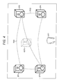
As shown in FIG. 4, four speakers SP1 through SP4 might be provided in a space, and a sound image is to be fixed at the position of a virtual sound source VSP3 located at the center position among these speakers SP1 through SP4.
In the example shown in FIG. 4, the speakers SP1 through SP4 are provided on the plane of a sphere having its center at an origin O (not shown), and the triangular area that is an area on the plane and is surrounded by the speakers SP1 through SP3 is an area TR31. Of the areas on the spherical plane having its center at the origin O, the triangular area surrounded by the speakers SP2 through SP4 is an area TR32.
The virtual sound source VSP3 is located on the lower right side of the area TR31. The virtual sound source VSP3 is also located on the upper left side of the area TR32.
Accordingly, in this case, three-dimensional VBAP should be performed with respect to the speakers SP1 through SP3, or three-dimensional VBAP should be performed with respect to the speakers SP2 through SP4. In either case, the same three-dimensional VBAP calculation result is obtained, and gains are determined so that only the two speakers SP2 and SP3 output sound, and the remaining speakers SP1 and SP4 do not output any sound.
By three-dimensional VBAP, in a case where the position at which a sound image is to be fixed is on the boundary line between triangular areas on a spherical plane connecting three speakers or on a side of a triangle on the spherical plane, only the two speakers located at the two ends of the side output sound.
In a case where only the two speakers SP2 and SP3 output sound as above, the user U11 situated in a sweet spot that is an optimum listening spot might move toward the left in the drawing as indicated by an arrow A11, for example, as shown in FIG. 5.
As a result, the head of the user U11 becomes closer to the speaker SP3, and the sound being output from the speaker SP3 becomes louder to the user U11. Therefore, the user U11 feels like the virtual sound source VSP3, or the sound image, has moved to the lower left as indicated by an arrow A12 in the drawing.
By three-dimensional VBAP, in a case where only two speakers output sound as shown in FIG. 5, if the user U11 moves away from the sweet spot only a short distance, the sound image moves in a direction perpendicular to the movement of the user U11. In such a case, the user U11 feels like the sound image has moved in a different direction from the direction of his/her movement, and therefore, has a feeling of strangeness. That is, the user U11 feels that the localization position of the sound image is unstable, and the sweet spot range becomes narrower.
In view of this, according to the present technology as opposed to the above described VBAP, a larger number of speakers than three, or four or more speakers, are made to output sound so that the localization position of a sound image becomes more stable, and the sweet spot range becomes wider accordingly.
Although the number of speakers that are made to output sound may be any number equal to or larger than four, explanation of an example case where four speakers are made to output sound is continued in the description below.
A sound image is to be fixed at the position of a virtual sound source VSP3 at the center position among four speakers SP1 through SP4, for example, as in the example shown in FIG. 4.
According to the present technology, two or three speakers are selected as a combination in such a case, and VBAP is performed with respect to different combinations of speakers, to calculate the gains of sounds that are output from the four speakers SP1 through SP4.
Accordingly, according to the present technology, all the four speakers SP1 through SP4 output sound as shown in FIG. 6, for example.
In such a case, if a user U11 moves to the left from the sweet spot as shown in an arrow A21 in FIG. 6, the position of the virtual sound source VSP3 or the localization position of the sound image only moves to the left as shown in an arrow A22 in the drawing. That is, the sound image does not move downward or in a direction perpendicular to the direction of movement of the user U11 as in the example shown in FIG. 5, but moves only in the same direction as the direction of movement of the user U11.
This is because, when the user U11 moves to the left, the user U11 becomes closer to the speaker SP3, but the speaker SP1 also exists above the speaker SP3. In this case, sound reaches the ears of the user U11 from the upper left and the lower left relative to the user U11, and therefore, the user U11 hardly feels that the sound image has moved downward.
Accordingly, the localization position of the sound image can be made more stable than by a conventional VBAP technique, and as a result, the sweet spot range can be made wider.
Next, the control on localization of sound according to the present technology is described in greater detail.
In the present technique, a vector that indicates a position at which a sound image is to be fixed is a vector P that has its starting point at the origin O (not shown) of a three-dimensional coordinate system, and the vector P is expressed by the following equation (3):
[Mathematical Formula 3]
P−g 1 L 1 +g 2 L 2 +g 3 L 3 +g 4 L 4  (3)
In the equation (3), the vectors L1 through L4 indicate three-dimensional vectors extending toward the positions of speakers SP1 through SP4 that are located in the vicinity of the localization position of the sound image and are arranged to surround the localization position of the sound image. Also, in the equation (3), g1 through g4 represent the coefficients that are to be calculated as the gains of sounds of the respective channels to be output from the speakers SP1 through SP4.
In the equation (3), the vector P is expressed as a linear sum of the four vectors L1 through L4. Since the vector P is a three-dimensional vector, the four coefficients g1 through g4 are not uniquely determined.
Therefore, according to the present technology, the respective coefficients g1, through g4 to be gains are calculated by the method described below.
A sound image is to be fixed at the center position of a tetragon on a spherical plane surrounded by the four speakers SP1 through SP4 shown in FIG. 4, or at the position of the virtual sound source VSP3.
First, one of the tetragon on the spherical plane having the speakers SP1 through SP4 as the corners is selected, and a virtual speaker (hereinafter referred to as “the virtual speaker”) is assumed to exist on the side.
As shown in FIG. 7, in the tetragon on the spherical plane having the speakers SP1 through SP4 at the corners, the side connecting the speakers SP3 and SP4 located at the lower left corner and the lower right corner in the drawing is selected, for example. The virtual speaker VSP′ is assumed to exist at the position of the intersection point between the side connecting the speakers SP3 and SP4 and a perpendicular extending from the position of the virtual sound source VSP3, for example.
Three-dimensional VBAP is then performed with respect to the three speakers: the virtual speaker VSP′, and the speakers SP1 and SP2 at the upper left corner and the upper right corner in the drawing. Specifically, a calculation is performed according to the same equation as the above described equation (2), to determine a coefficient g1, a coefficient g2, and a coefficient g′, which are to be the gains of sounds to be output from the speaker SP1, the speaker SP2, and the virtual speaker VSP′.
In FIG. 7, a vector P is expressed as a linear sum of three vectors extending from the origin O, or of the vector L1 extending toward the speaker SP1, the vector L2 extending toward the speaker SP2, and the vector L′ extending toward the virtual speaker VSP′. That is, the vector P is expressed as P=g1L1+g2L2+g′L′.
Here, to fix a sound image at the position of the virtual sound source VSP3, the virtual speaker VSP′ needs to output sound with the gain g′, but the virtual speaker VSP′ does not actually exist. Therefore, as shown in FIG. 8, the two speakers SP3 and SP4 at the two ends of the side on which the virtual speaker VSP′ is located in the tetragon are used to fix the sound image at the position of the virtual speaker VSP′ according to the present technology. In this manner, the virtual speaker VSP′ is realized.
Specifically, two-dimensional VBAP is performed with respect to the two speakers SP3 and SP4, which are located at the two ends of the side on which the virtual speaker VSP′ is located on the spherical plane. That is, a calculation is performed according to the same equation as the above described equation (1), to calculate a coefficient g3′ and a coefficient g4′, which are to be the gains of sounds to be output from the speaker SP3 and the speaker SP4, respectively.
In the example shown in FIG. 8, the vector L′ extending toward the virtual speaker VSP′ is expressed as a linear sum of the vector L3 extending toward the speaker SP3 and the vector L4 extending toward the speaker SP4. That is, the vector L′ is expressed as L′=g3′L3+g4′L4.
The value g′g3′ obtained by multiplying the calculated coefficient g3′ by the coefficient g′ is set as the gain of the sound to be output from the speaker SP3, and the value g′g4′ obtained by multiplying the calculated coefficient g4′ by the coefficient g′ is set as the gain of the sound to be output from the speaker SP4. In this manner, the virtual speaker VSP′ that outputs sound with the gain g′ is realized by the speakers SP3 and SP4.
Here, the value of g′g3′ to be a gain value is the value of the coefficient g3 in the above described equation (3), and the value of g′g4′ to be a gain value is the value of the coefficient g4 in the above described equation (3).
The values g1, g2, g′g3′, and g′g4′, which have been obtained as above and are not 0, are set as the gains of sounds of the respective channels to be output from the speakers SP1 through SP4. In this manner, the four speakers are made to output sound, and the sound image can be fixed at the target position.
As the sound image is fixed at a position by causing the four speakers to output sound as above, the localization position of the sound image can be made more stable than a sound image fixed at a position by a conventional VBAP technique. Accordingly, the sweet spot range can be widened.
<Example Structure of a Sound Processing Apparatus>
Next, a specific example to which the above described present technology is applied is described. FIG. 9 is a diagram showing an example structure of an embodiment of a sound processing apparatus to which the present technology is applied.
A sound processing apparatus 11 performs gain adjustment on a monaural sound signal supplied from outside for respective channels. By doing so, the sound processing apparatus 11 generates sound signals of N channels (N≥5), and supplies the sound signals to speakers 12-1 through 12-N corresponding to the N channels.
The speakers 12-1 through 12-N output sounds of the respective channels based on the sound signals supplied from the sound processing apparatus 11. That is, the speakers 12-1 through 12-N are sound outputting units serving as sound sources that output sounds of the respective channels. Hereinafter, when there is no particular need to distinguish the speakers 12-1 through 12-N from one another, the speakers 12-1 through 12-N will be also referred to simply as the speakers 12. Although the speakers 12 are not included in the sound processing apparatus 11 in FIG. 9, the speakers 12 may be included in the sound processing apparatus 11. Also, the respective components constituting the sound processing apparatus 11 and the speakers 12 may be provided in several apparatuses, to form a sound processing system including the respective components of the sound processing apparatus 11 and the speakers 12.
The speakers 12 are arranged to surround the position at which a user is assumed to exist when viewing and listening to content or the like (the position will be hereinafter also referred to simply as the user position). For example, the respective speakers 12 are arranged at positions on the plane of a sphere having its center at the user position. In other words, the respective speakers 12 are arranged at positions at the same distance from the user. Also, sound signals may be supplied from the sound processing apparatus 11 to the speakers 12 in a wired or wireless manner.
The sound processing apparatus 11 includes a speaker selecting unit 21, a gain calculating unit 22, a gain determining unit 23, a gain outputting unit 24, and a gain adjusting unit 25.
Sound signals of sound collected by a microphone attached to an object such as a mobile object, and position information about the object are supplied to the sound processing apparatus 11.
Based on the object's position information supplied from outside, the speaker selecting unit 21 identifies the position at which a sound image of sound to be emitted from the object in the space including the speakers 12 is to be fixed (the position to be identified will be hereinafter also referred to as the target sound image position), and supplies the result of the identification to the gain calculating unit 22.
Based on the target sound image position, the speaker selecting unit 21 selects four speakers 12 to output sound as processing-target speakers 12 from among the N speakers 12, and supplies select information indicating the result of the selection to the gain calculating unit 22, the gain determining unit 23, and the gain outputting unit 24.
The gain calculating unit 22 calculates gains of the processing-target speakers 12 based on the select information supplied from the speaker selecting unit 21 and the target sound image position, and supplies the gains to the gain outputting unit 24. The gain determining unit 23 determines gains of the speakers 12 other than the processing-target speakers based on the select information supplied from the speaker selecting unit 21, and supplies the gains to the gain outputting unit 24. For example, the gains of the speakers 12 that are not the processing targets are set at “0”. That is, the speakers 12 that are not the processing targets are controlled not to output any sound of the object.
The gain outputting unit 24 supplies the N gains supplied from the gain calculating unit 22 and the gain determining unit 23, to the gain adjusting unit 25. At this point, the gain outputting unit 24 determines the supply destinations of the N gains supplied from the gain calculating unit 22 and the gain determining unit 23 in the gain adjusting unit 25 based on the select information supplied from the speaker selecting unit 21.
Based on the respective gains supplied from the gain outputting unit 24, the gain adjusting unit 25 performs gain adjustment on the object's sound signal supplied from outside, and supplies the resultant sound signals of the N channels to the speakers 12, so that the speakers 12 output sound.
The gain adjusting unit 25 includes amplifiers 31-1 through 31-N. Based on the gains supplied from the gain outputting unit 24, the amplifiers 31-1 through 31-N perform gain adjustment on the sound signal supplied from outside, and supply the resultant sound signals to the speakers 12-1 through 12-N.
Hereinafter, when there is no need to distinguish the amplifiers 31-1 through 31-N from one another, the amplifiers 31-1 through 31-N will be also referred to simply as the amplifiers 31.
<Example Structure of the Gain Calculating Unit>
The gain calculating unit 22 shown in FIG. 9 has the structure shown in FIG. 10, for example.
The gain calculating unit 22 shown in FIG. 10 includes a virtual speaker position determining unit 61, a three-dimensional gain calculating unit 62, a two-dimensional gain calculating unit 63, a multiplier 64, and a multiplier 65.
The virtual speaker position determining unit 61 determines the position of a virtual speaker based on information indicating the target sound image position and the select information supplied from the speaker selecting unit 21. The virtual speaker position determining unit 61 supplies the information indicating the target sound image position, the select information, and information indicating the position of the virtual speaker to the three-dimensional gain calculating unit 62, and supplies the select information and the information indicating the position of the virtual speaker to the two-dimensional gain calculating unit 63.
Based on the respective pieces of the information supplied from the virtual speaker position determining unit 61, the three-dimensional gain calculating unit 62 performs three-dimensional VBAP with respect to two speakers 12 of the processing-target speakers 12, and the virtual speaker. The three-dimensional gain calculating unit 62 then supplies the gains of the two speakers 12 obtained through the three-dimensional VBAP to the gain outputting unit 24, and supplies the gain of the virtual speaker to the multiplier 64 and the multiplier 65.
Based on the respective pieces of the information supplied from the virtual speaker position determining unit 61, the two-dimensional gain calculating unit 63 performs two-dimensional VBAP with respect to two speakers 12 of the processing-target speakers 12, and supplies the resultant gains of the speakers 12 to the multiplier 64 and the multiplier 65.
The multiplier 64 obtains ultimate gains of the speakers 12 by multiplying the gains supplied from the two-dimensional gain calculating unit 63 by the gains supplied from the three-dimensional gain calculating unit 62, and supplies the ultimate gains to the gain outputting unit 24. The multiplier 65 obtains ultimate gains of the speakers 12 by multiplying the gain supplied from the two-dimensional gain calculating unit 63 by the gains supplied from the three-dimensional gain calculating unit 62, and supplies the ultimate gains to the gain outputting unit 24.
<Description of a Sound Localization Control Process>
Meanwhile, when object's position information and an object's sound signal are supplied to the sound processing apparatus 11, and an instruction to output sound of the object is issued, the sound processing apparatus 11 starts a sound localization control process, to cause sound of the object to be output, and fix the sound image at an appropriate position.
Referring now to the flowchart in FIG. 11, the sound localization control process to be performed by the sound processing apparatus 11 is described.
In step S11, the speaker selecting unit 21 selects processing-target speakers 12 based on the object's position information supplied from outside.
Specifically, the speaker selecting unit 21 identifies a target sound image position based on the object's position information, for example, and selects, from among the N speakers 12, the processing-target speakers 12 that are four speakers 12 that are located in the vicinity of the target sound image position and are arranged to surround the target sound image position.
In a case where the position of the virtual sound source VSP3 shown in FIG. 7 is set as the target sound image position, for example, the speakers 12 equivalent to the four speakers SP1 through SP4 surrounding the virtual sound source VSP3 are selected as the processing-target speakers 12.
The speaker selecting unit 21 supplies the information indicating the target sound image position to the virtual speaker position determining unit 61, and supplies the select information indicating the four processing-target speakers 12 to the virtual speaker position determining unit 61, the gain determining unit 23, and the gain outputting unit 24.
In step S12, the virtual speaker position determining unit 61 determines the position of the virtual speaker based on the information indicating the target sound image position and the select information supplied from the speaker selecting unit 21. As in the example shown in FIG. 7, for example, the position of the intersection point between the side connecting the speakers 12 located at the lower left corner and the lower right corner relative to the user among the processing-target speakers 12 on a spherical plane, and the perpendicular extending from the target sound image position toward the side is set as the position of the virtual speaker.
After the position of the virtual speaker is determined, the virtual speaker position determining unit 61 supplies the information indicating the target sound image position, the select information, and the information indicating the position of the virtual speaker to the three-dimensional gain calculating unit 62, and supplies the select information and the information indicating the position of the virtual speaker to the two-dimensional gain calculating unit 63.
The position of the virtual speaker may be any position, as long as it is located on a side of a tetragon on the spherical plane, the tetragon having the four processing-target speakers 12 at the respective corners. Even in a case where the number of processing-target speakers 12 is five or larger, the position of the virtual speaker may be any position on a side of a polygon on the spherical plane, the polygon having those processing-target speakers 12 at the corners.
In step S13, the three-dimensional gain calculating unit 62 calculates gains for the virtual speaker and two processing-target speakers 12 based on the information indicating the target sound image position, the select information, and the information about the position of the virtual speaker, the information having been supplied from the virtual speaker position determining unit 61.
Specifically, the three-dimensional gain calculating unit 62 determines the vector P to be the three-dimensional vector indicating the target sound image position, and determines the vector L′ to be the three-dimensional vector extending toward the virtual speaker. The three-dimensional gain calculating unit 62 also determines the vector L1 to be the vector extending toward the speaker 12 in the same positional relationship as the speaker SP1 shown in rig. 7 among the processing-target speakers 12, and the vector L2 to be the vector extending toward the speaker 12 in the same positional relationship as the speaker SP2.
The three-dimensional gain calculating unit 62 then determines the equation expressing the vector P as the linear sum of the vector L′, the vector L1, and the vector L2, and performs calculation according to the equation, to calculate gains that are the coefficient g′, the coefficient g1, and the coefficient g2 of the vector L′, the vector L1, and the vector L2, respectively. That is, the same calculation as the above described calculation according to the equation (2) is performed.
The three-dimensional gain calculating unit 62 supplies the calculated coefficients g1 and g2 of the speakers 12 in the same positional relationships as the speakers SP1 and SP2, as the gains of the sounds to be output from these speakers 12, to the gain outputting unit 24.
The three-dimensional gain calculating unit 62 also supplies the calculated coefficient g′ of the virtual speaker, as the gain of the sound to be output from the virtual speaker, to the multiplier 64 and the multiplier 65.
In step S14, the two-dimensional gain calculating unit 63 calculates gains for two processing-target speakers 12 based on the select information and the information about the position of the virtual speaker, the information having been supplied from the virtual speaker position determining unit 61.
Specifically, the two-dimensional gain calculating unit 63 determines the vector L′ to be the three-dimensional vector indicating the position of the virtual speaker. The two-dimensional gain calculating unit 63 also determines the vector L3 to be the vector extending toward the speaker 12 in the same positional relationship as the speaker SP3 shown in FIG. 8 among the processing-target speakers 12, and the vector L4 to be the vector extending toward the speaker 12 in the same positional relationship as the speaker SP4.
The two-dimensional gain calculating unit 63 then determines the equation expressing the vector L′ as the linear sum of the vector L3 and the vector L4, and performs calculation according to the equation, to calculate gains that are the coefficient g3′ and the coefficient g4′ of the vector L3 and the vector L4, respectively. That is, the same calculation as the above described calculation according to the equation (1) is performed.
The two-dimensional gain calculating unit 63 supplies the calculated coefficients g3′ and g4′ of the speakers 12 in the same positional relationships as the speakers SP3 and SP4, as the gains of the sounds to be output from these speakers 12, to the multiplier 64 and the multiplier 65.
In step S15, the multiplier 64 and the multiplier 65 multiply the gains g3′ and g4′ supplied from the two-dimensional gain calculating unit 63 by the gain g′ of the virtual speaker supplied from the three-dimensional gain calculating unit 62, and supplies the resultant gains to the gain outputting unit 24.
Accordingly, as the ultimate gain of the speaker 12 in the same positional relationship as the speaker SP3 shown in FIG. 8 among the four processing-target speakers 12, the gain g3=g′g3′ is supplied to the gain outputting unit 24. Likewise, as the ultimate gain of the speaker 12 in the same positional relationship as the speaker SP4 shown in FIG. 8 among the four processing-target speakers 12, the gain g4=g′g4′ is supplied to the gain outputting unit 24.
In step S16, the gain determining unit 23 determines gains of the speakers 12 other than the processing-target speakers based on the select information supplied from the speaker selecting unit 21, and supplies the gains to the gain outputting unit 24. For example, the gains of all the speakers 12 that are not the processing targets are set at “0”.
After the gains g1, g2, g′g3′, and g′g4′ from the gain calculating unit 22, and the gain “0” from the gain determining unit 23 are supplied to the gain outputting unit 24, the gain outputting unit 24 supplies these gains to the amplifiers 31 of the gain adjusting unit 25 based on the select information supplied from the speaker selecting unit 21.
Specifically, the gain outputting unit 24 supplies the gains g1, g2, g′g3′, and g′g4′ to the amplifiers 31 that supply sound signals to the respective processing-target speakers 12, or the respective speakers 12 equivalent to the speakers SP1 through SP4 shown in FIG. 7. For example, in a case where the speaker 12 equivalent to the speaker SP1 is the speaker 12-1, the gain outputting unit 24 supplies the gain g1 to the amplifier 31-1.
The gain outputting unit 24 also supplies the gain “0” supplied from the gain determining unit 23, to the amplifiers 31 that supply sound signals to the speakers 12 that are not processing targets.
In step S17, the amplifiers 31 of the gain adjusting unit 25 perform gain adjustment on an object's sound signal supplied from outside based on the gains supplied from the gain outputting unit 24, and supply the resultant sound signals to the speakers 12, so that the speakers 12 output sound.
The respective speakers 12 output sound based on the sound signals supplied from the amplifiers 31. More specifically, only the four processing-target speakers 12 output sound. Accordingly, a sound image can be fixed at a target position. As sound is output from the speakers 12, the sound localization control process comes to an end.
As described above, the sound processing apparatus 11 selects four speakers 12 as processing targets based on position information about an object, and performs VBAP with respect to a combination of two or three speakers among those speakers 12 and a virtual speaker. The sound processing apparatus 11 then performs gain adjustment on a sound signal based on the gains of the respective processing-target speakers 12, the gains having been obtained through VBAP performed on different combinations.
Accordingly, sound can be output from the four speakers 12 surrounding the target sound image position, and localization of sound can be made more stable. As a result, the sweet spot range can be made wider.
<Second Embodiment>
<Gain Calculation>
In the above described example, two or three speakers to form one combination of speakers are selected from among five speakers including a virtual speaker, and VBAP is performed on more than one combination, to calculate gains of the processing-target speakers 12. According to the present technology, however, it is also possible to calculate gains by selecting combinations from among four processing-target speakers 12, and performing VBAP on each of the combinations, without any virtual speaker determined.
In such a case, the number of times VBAP should be performed varies depending on the target sound image position, as shown in FIG. 12, for example. In FIG. 12, the components equivalent to those shown in FIG. 7 are denoted by the same reference numerals as those used in FIG. 7, and explanation of them will not be unnecessarily repeated.
In a case where the position of a virtual sound source, or a target sound image position, is the position indicated by an arrow Q11, for example, the position indicated by the arrow Q11 is in a triangular area surrounded by a speaker SP1, a speaker SP2, and a speaker SP4 on a spherical plane. Accordingly, if three-dimensional VBAP is performed with respect to the combination of speakers consisting of the speakers SP1, SP2, and SP4 (this combination will be hereinafter also referred to as the first combination), the gains of sounds to be output from the three speakers SP1, SP2, and SP4 are determined.
Meanwhile, the position indicated by the arrow Q11 is also a position in a triangular area surrounded by the speaker SP2, a speaker SP3, and the speaker SP4 on the spherical plane. Accordingly, if three-dimensional VBAP is performed with respect to the combination of speakers consisting of the speakers SP2, SP3, and SP4 (this combination will be hereinafter also referred to as the second combination), the gains of sounds to be output from the three speakers SP2, SP3, and SP4 are determined.
Here, each of the gains of the speakers not used in the first combinations and the second combinations is set at “0”, so that two sets of gains can be obtained as the respective gains of the four speakers SP1 through SP4 in the first and second combinations.
For each of the speakers, the sum of the gains of the speaker obtained in the first and the second combinations is obtained as a gain sum. For example, where the gain of the speaker SP1 in the first combination is g1(1), and the gain of the speaker SP1 in the second combination is g1(2), the gain sum gs1 of the speaker SP1 is expressed as the gain sum gs1=g1(1)|g1(2).
Since the speaker SP1 is not included in the second combination, g1(2) is 0. Since the speaker SP1 is included in the first combination of speakers, g1(1) is not 0. as a result, the gain sum gs1 of the speaker SP1 is not 0. The same applies to the gain sums of the other speakers SP2 through SP4.
As the gain sums of the respective speakers are determined in the above manner, the values obtained by normalizing the gain sums of the respective speakers with the sum of squares of these gain sums are set as the ultimate gains of these speakers, or more specifically, as the gains of the sounds to be output form the speakers.
As the gains of the respective speakers SP1 through SP4 are determined in the above manner, gains that are not 0 are invariably obtained. Accordingly, each of the four speakers SP1 through SP4 can be made to output sound, and a sound image can be fixed at a desired position.
In the description below, the gain of a speaker SPk (1≤k≤4) in a mth combination (1≤m≤4) is represented by gk(m). The gain sum of a speaker SPk (1≤k≤4) is represented by gsk.
Further, in a case where the target sound image position is the position indicated by an arrow Q12, or the position of the intersection point between the line connecting the speaker SP2 and the speaker SP3 and the line connecting the speaker SP1 and the speaker SP4 on the spherical plane, there are four combinations of three speakers.
Specifically, where there is the combination of the speaker SP1, the speaker SP2, and the speaker SP3 (this combination will be hereinafter referred to as the first combination), the combination of the speaker SP1, the speaker SP2, and the speaker SP4 (this combination will be hereinafter referred to as the second combination) is possible. Also, where there is the combination of the speaker SP1, the speaker SP3, and the speaker SP4 (this combination will be hereinafter referred to as the third combination), the combination of the speaker SP2, the speaker SP3, and the speaker SP4 (this combination will be hereinafter referred to as the fourth combination) is possible.
In this case, three-dimensional VBAP is performed on each of the first through fourth combinations, to determine the gains of the respective speakers. The sum of the four gains obtained with respect to the same speaker is set as a gain sum, and the values obtained by normalizing the gain sums of the respective speakers with the sum of squares of the four gain sums determined with respect to the respective speakers are set as the ultimate gains of these speakers.
In a case where the target sound image position is the position indicated by the arrow Q12, if the tetragon formed with the speakers SP1 through SP4 on the spherical plane is a rectangle or the like, the same result of calculation as three-dimensional VBAP is obtained from the first combination and the fourth combination, for example. Accordingly, if three-dimensional VBAP is performed with respect to appropriate two combinations such as the first and second combinations in this case, the gains of the respective speakers can be obtained. However, in a case where the tetragon formed with the speakers SP1 through SP4 on the spherical plane is not a rectangle or the like but an asymmetric tetragon, it is necessary to perform three-dimensional VBAP with respect to each of the four combinations.
<Example Structure of the Gain Calculating Unit>
In a case where gains are calculated by selecting combinations of speakers from among four processing-target speakers 12 and performing VBAP with respect to each of those combinations, without any virtual speaker determined, the gain calculating unit 22 shown in FIG. 9 has the structure shown in FIG. 13, for example.
The gain calculating unit 22 shown in FIG. 13 includes a selecting unit 91, a three-dimensional gain calculating unit 92-1, a three-dimensional gain calculating unit 92-2, a three-dimensional gain calculating unit 92-3, a three-dimensional gain calculating unit 92-4, and an adder 93.
Based on information indicating the target sound image position and select information supplied from a speaker selecting unit 21, the selecting unit 91 determines combinations of three speakers 12 surrounding the target sound image position from among four speakers 12 selected as the processing targets. The selecting unit 91 supplies information indicating the combinations of speakers 12 and the information indicating the target sound image position to the three-dimensional gain calculating units 92-1 through 92-4.
The three-dimensional gain calculating units 92-1 through 92-4 perform three-dimensional VBAP based on the information indicating the combinations of speakers 12 and the information indicating the target sound image position supplied from the selecting unit 91, and supply the resultant gains of the respective speakers 12 to the adder 93. In the description below, where there is no particular need to distinguish the three-dimensional gain calculating units 92-1 through 92-4 from one another, the three-dimensional gain calculating units 92-1 through 92-4 will be also referred to simply as the three-dimensional gain calculating units 92.
The adder 93 determines gain sums based on the gains of the respective processing-target speakers 12 supplied from the three-dimensional gain calculating units 92-1 through 92-4, and calculates the ultimate gains of the respective processing-target speakers 12 by normalizing these gain sums. The adder 93 then supplies the ultimate gains to the gain outputting unit 24.
<Description of a Sound Localization Control Process>
Referring now to the flowchart in FIG. 14, a sound localization control process to be performed in a case where the gain calculating unit 22 has the structure shown in FIG. 13 is described.
The procedure in step S41 is the same as the procedure in step S11 in FIG. 11, and therefore, explanation thereof is not repeated herein.
In step S42, the selecting unit 91 determines combinations of speakers 12 based on the information indicating the target sound image position and the select information supplied from the speaker selecting unit 21, and supplies information indicating the combinations of speakers 12 and the information indicating the target sound image position to the three-dimensional gain calculating units 92.
In a case where the target sound image position is the position indicated by the arrow Q11 in FIG. 12, for example, the combination (the first combination) of the speakers 12 including the three speakers 12 equivalent to the speakers SP1, SP2, and SP4 is determined. Also, the combination (the second combination) of the speakers 12 including the three speakers 12 equivalent to the speakers SP2, SP3, and SP4 is determined.
In this case, the selecting unit 91 supplies information indicating the first combination of speakers 12 and the information indicating the target sound image position to the three-dimensional gain calculating unit 92-1, and supplies information indicating the second combination of speakers 12 and the information indicating the target sound image position to the three-dimensional gain calculating unit 92-2. In this case, the information indicating the combinations of speakers 12 and the like are not supplied to the three-dimensional gain calculating units 92-3 and 92-4, and the three-dimensional gain calculating units 92-3 and 92-4 do not perform any calculation of three-dimensional VBAP, either.
In step S43, based on the information indicating the combinations of speakers 12 and the information indicating the target sound image position supplied from the selecting unit 91, the three-dimensional gain calculating units 92 calculate gains of the respective speakers 12 in the combinations of speakers 12, and supply the gains to the adder 93.
Specifically, the three-dimensional gain calculating units 92 determine gains of the respective speakers 12 by carrying out the same procedure as that in step S13 in FIG. 11 with respect to the three speakers 12 indicated by the information indicating the combination of speakers 12. That is, the same calculation as the above described calculation according to the equation (2) is performed. The gain of the remaining one speaker 12 other than the three speakers 12 indicated by the information indicating the combination of speakers 12 among the four processing-target speakers 12 is set at “0”.
In a case where the two combinations, the first and second combinations, are determined in step S42, for example, the three-dimensional gain calculating unit 92-1 calculates gains of the respective speakers 12 through three-dimensional VBAP with respect to the first combination. The three-dimensional gain calculating unit 92-2 calculates gains of the respective speakers 12 through three-dimensional VBAP with respect to the second combination.
Specifically, the combination of the speakers including the three speakers 12 equivalent to the speakers SP1, SP2, and SP4 shown in FIG. 12 is determined as the first combination. In this case, the three-dimensional gain calculating unit 92-1 calculates the gain g1(1) of the speaker 12 equivalent to the speaker SP1, the gain g2(1) of the speaker 12 equivalent to the speaker SP2, and the gain g4(1) of the speaker 12 equivalent to the speaker SP4. Meanwhile, the gain g3(1) of the speaker 12 equivalent to the speaker SP3 is set at “0”.
In step S44, the adder 93 calculates ultimate gains of the processing-target speakers 12 based on the gains of the respective speakers 12 supplied from the three-dimensional gain calculating units 92, and supplies the ultimate gains to the gain outputting unit 24.
For example, the adder 93 calculates the gain sum gs1 of the speaker 12 equivalent to the speaker SP1 by determining the sum of the gains g1(1), g1(2), g1(3), and g1(4) of the speaker 12, the gains having been supplied from the three-dimensional gain calculating units 92. Likewise, the adder 93 also calculates the gain sum gs2 of the speaker 12 equivalent to the speaker SP2, the gain sum gs3 of the speaker 12 equivalent to the speaker SP3, and the gain sum gs4 of the speaker 12 equivalent to the speaker SP4.
The adder 93 then determines the ultimate gain g1 (coefficient g1) of the speaker 12 equivalent to the speaker SP1 by normalizing the gain sum gs1 of the speaker 12 equivalent to the speaker SP1 with the sum of squares of the gain sums gs1 through gs4. The adder 93 also determines the ultimate gains g2 through g4 of the speakers 12 equivalent to the speakers SP2 through SP4 through the same calculation as above.
After the gains of the processing-target speakers 12 are determined in the above manner, the procedures in steps S45 and S46 are carried out, and the sound localization control process then comes to an end. However, these procedures are the same as the procedures in steps S16 and S17 in FIG. 11, and therefore, explanation of them is not repeated herein.
As described above, the sound processing apparatus 11 selects four speakers 12 as processing targets based on position information about an object, and performs VBAP with respect to combinations of speakers 12 that are three speakers 12 among the four processing-target speakers 12. The sound processing apparatus 11 then determines the ultimate gains of the respective processing-target speakers 12 by determining the sum of gains of each speaker 12 obtained through VBAP performed with respect to different combinations, and performs gain adjustment on sound signals.
Accordingly, sound can be output from the four speakers 12 surrounding the target sound image position, and localization of sound can be made more stable. As a result, the sweet spot range can be made wider.
Although an example case where four speakers 12 surrounding the target sound image position are the processing-target speakers 12 has been described in this embodiment, the number of speakers 12 to be selected as the processing targets may be four or larger.
For example, in a case where five speakers 12 are selected as the processing-target speakers 12, the combination of speakers 12 consisting of three speakers 12 surrounding the target sound image position is selected as one combination among the five speakers 12.
Specifically, as shown in FIG. 15, speakers 12 equivalent to five speakers SP1 through SP5 are selected as processing-target speakers 12, and the target sound image position is the position indicated by an arrow Q21.
In this case, the combination of the speakers SP1, SP2, and SP3 is selected as a first combination, and the combination of the speakers SP1, SP2, and SP4 is selected as a second combination. Also, the combination of the speakers SP1, SP2, and SP5 is selected as a third combination.
Gains of the respective speakers are determined with respect to the first through third combinations, and ultimate gains are calculated from the gain sums of the respective speakers. That is, with respect to the first through third combinations, the procedure in step S43 in FIG. 14 is carried out, and the procedures in steps S44 through S46 are then carried out.
As described above, in a case where five or more speakers 12 are selected as the processing-target speakers 12, sound is also output from all the processing-target speakers 12, so that a sound image can be fixed.
The above described series of processes may be performed by hardware or may be performed by software. Where the series of processes are to be performed by software, the program that forms the software is installed into a computer. Here, the computer may be a computer incorporated into special-purpose hardware, or may be a general-purpose computer that can execute various kinds of functions as various kinds of programs are installed thereinto.
FIG. 16 is a block diagram showing an example structure of the hardware of a computer that performs the above described series of processes in accordance with programs.
In the computer, a CPU 801, a ROM 802, and a RAM 803 are connected to one another by a bus 804.
An input/output interface 805 is further connected to the bus 804. An input unit 806, an output unit 807, a recording unit 808, a communication unit 809, and a drive 810 are connected to the input/output interface 805.
The input unit 806 is formed with a keyboard, a mouse, a microphone, an imaging device, and the like. The output unit 807 is formed with a display, a speaker, and the like. The recording unit 808 is formed with a hard disk, a nonvolatile memory, or the like. The communication unit 809 is formed with a network interface or the like. The drive 810 drives a removable medium 811 such as a magnetic disk, an optical disk, a magnetooptical disk, or a semiconductor memory.
In the computer having the above described structure, the CPU 801 loads a program recorded in the recording unit 808 into the RAM 803 via the input/output interface 805 and the bus 804, for example, and executes the program, so that the above described series of processes are performed.
The program to be executed by the computer (the CPU 801) may be recorded on the removable medium 811 as a package medium to be provided, for example. Alternatively, the program can be provided via a wired or wireless transmission medium such as a local area network, the Internet, or digital satellite broadcasting.
In the computer, the program can be installed into the recording unit 808 via the input/output interface 805 when the removable medium 811 is mounted on the drive 810. The program can also be received by the communication unit 809 via a wired or wireless transmission medium, and be installed into the recording unit 808. Alternatively, the program may be installed beforehand into the ROM 802 or the recording unit 808.
The program to be executed by the computer may be a program for performing processes in chronological order in accordance with the sequence described in this specification, or may be a program for performing processes in parallel or performing a process when necessary, such as when there is a call.
It should be noted that embodiments of the present technology are not limited to the above described embodiments, and various modifications may be made to them without departing from the scope of the present technology.
For example, the present technology can be embodied in a cloud computing structure in which one function is shared among apparatuses via a network, and processing is performed by the apparatuses cooperating with one another.
The respective steps described with reference to the above described flowcharts can be carried out by one device or can be shared among devices.
In a case where more than one process is included in one step, the processes included in the step can be performed by one device or can be shared among devices.
Further, the present technology may take the following forms.
[1]
A sound processing apparatus including:
four or more sound outputting units;
a gain calculating unit that determines output gains of sounds to be output from the four or more sound outputting units located close to a sound image localization position as a target position by calculating gains of sounds to be output from the sound outputting units based on a positional relationship between the sound outputting units with respect to each of different combinations among combinations of two or three of the four or more sound outputting units, the output gains being to be used for fixing a sound image at the sound image localization position; and
a gain adjusting unit that performs gain adjustment on sounds to be output from the sound outputting units based on the output gains.
[2]
The sound processing apparatus of [1], wherein at least four of the output gains each have a value other than 0.
[3]
The sound processing apparatus of [1] or [2], wherein the gain calculating unit includes:
a first gain calculating unit that calculates output gains of a virtual sound outputting unit and two of the sound outputting units based on a positional relationship among the virtual sound outputting unit, the two of the sound outputting units, and the sound image localization position;
a second gain calculating unit that calculates gains of other two of the sound outputting units than the two of the sound outputting units based on a positional relationship among the other two of the sound outputting units and the virtual sound outputting unit, the gains of the other two of the sound outputting units being to be used for fixing a sound image at a position of the virtual sound outputting unit; and
a calculating unit that calculates output gains of the other two of the sound outputting units based on the gains of the other two of the sound outputting units and the output gain of the virtual sound outputting unit.
[4]
The sound processing apparatus of [3], wherein the calculating unit calculates the output gains of the other two of the sound outputting units by multiplying the gains of the other two of the sound outputting units by the output gain of the virtual sound outputting unit.
[5]
The sound processing apparatus of [3] or [4], wherein the position of the virtual sound outputting unit is on a side of a polygon having the four or more sound outputting units at the corners thereof.
[6]
The sound processing apparatus of [1] or [2], wherein the gain calculating unit includes:
a virtual gain calculating unit that calculates output gains of three of the sound outputting units based on a positional relationship among the three of the sound outputting units and the sound image localization position; and
a calculating unit that calculates ultimate output gains of the sound outputting units based on the output gains calculated by the virtual gain calculating unit calculating the output gains with respect to different combinations among the combinations.
[7]
The sound processing apparatus of [6], wherein the calculating unit calculates an ultimate output gain of the same one of the sound outputting units by determining a sum of the output gains determined with respect to the same one of the sound outputting units.
REFERENCE SIGNS LIST
  • 11 Sound processing apparatus
  • 12-1 through 12-N, and 12 Speaker
  • 21 Speaker selecting unit
  • 22 Gain calculating unit
  • 25 Gain adjusting unit
  • 61 Virtual speaker position determining unit
  • 62 Three-dimensional gain calculating unit
  • 63 Two-dimensional gain calculating unit
  • 64 Multiplier
  • 65 Multiplier
  • 91 Selecting unit
  • 92-1 through 92-4, and 92 Three-dimensional gain calculating unit
  • 93 Adder

Claims (7)

The invention claimed is:
1. A sound processing apparatus comprising:
at least four speakers;
virtual speaker position determining circuitry configured to determine a position of a virtual speaker based on positions of the at least four speakers;
virtual speaker gain calculating circuitry configured to calculate a gain of the virtual speaker at least by performing three-dimensional Vector Base Amplitude Panning (VBAP) based on a positional relationship among the virtual speaker, two speakers of the at least four speakers, and a sound image localization position; and
gain adjusting circuitry configured to perform gain adjustment on sounds to be output from at least the two speakers based on the gain of the virtual speaker, wherein the at least four speakers are configured to output sounds to a listener according to output of the gain adjusting circuitry.
2. The sound processing apparatus according to claim 1, wherein gains of the at least four speakers each have a value other than 0.
3. The sound processing apparatus according to claim 2, wherein the virtual speaker gain calculating circuitry is further configured to calculate gains of the two speakers of the at least four speakers based on the positional relationship among the virtual speaker, the two speakers of the at least two speakers, and the sound image localization position, and wherein the sound process apparatus further comprises:
other gain calculating circuitry configured to calculate gains of other two speakers of the at least four speakers than the two speakers of the at least four speakers based on a positional relationship among the other two speakers and the virtual speaker, the gains of the other two speakers to be used for fixing a sound image at the position of the virtual speaker; and
calculating circuitry configured to calculate output gains of the other two speakers based on the gains of the other two speakers and an output gain of the virtual sound outputting unit.
4. The sound processing apparatus according to claim 3, wherein the calculating circuitry is configured to calculate the output gains of the other two of the sound outputting units by multiplying the gains of the other two of the sound outputting units by the output gain of the virtual sound outputting unit.
5. The sound processing apparatus according to claim 3, wherein the position of the virtual speaker is on a side of a polygon having the at least four speakers at corners thereof.
6. A sound processing apparatus comprising:
virtual speaker position determining circuitry configured to determine a position of a virtual speaker based on positions of four speakers located near the virtual speaker;
virtual speaker gain calculating circuitry configured to calculate a gain of the virtual speaker by performing three-dimensional Vector Base Amplitude Panning (VBAP) with respect to the virtual speaker and two speakers among the four speakers, based on a positional relationship among the virtual speaker, the two speakers, and a sound image localization position; and
gain adjusting circuitry configured to perform gain adjustment on sounds to be output from at least the two speakers based on the gain of the virtual speaker, and to output a result of the gain adjustment to cause the four speakers to output sounds to a listener according to the result of the gain adjustment.
7. A sound processing method comprising acts of:
determining a position of a virtual speaker based on positions of four speakers located near the virtual speaker;
calculating a gain of the virtual speaker by performing three-dimensional Vector Base Amplitude Panning (VBAP) with respect to the virtual speaker and two speakers among the four speakers, based on a positional relationship among the virtual speaker, the two speakers, and a sound image localization position;
performing gain adjustment on sounds to be output from at least the two speakers based on the gain of the virtual speaker; and
causing the four speakers to output sounds to a listener according to a result of the gain adjustment.
US15/932,368 2013-04-26 2018-02-16 Sound processing apparatus and sound processing system Active US10455345B2 (en)

Priority Applications (5)

Application Number Priority Date Filing Date Title
US15/932,368 US10455345B2 (en) 2013-04-26 2018-02-16 Sound processing apparatus and sound processing system
US16/444,589 US11272306B2 (en) 2013-04-26 2019-06-18 Sound processing apparatus and sound processing system
US17/402,461 US11412337B2 (en) 2013-04-26 2021-08-13 Sound processing apparatus and sound processing system
US17/835,783 US11968516B2 (en) 2013-04-26 2022-06-08 Sound processing apparatus and sound processing system
US18/132,286 US20230247379A1 (en) 2013-04-26 2023-04-07 Sound processing apparatus and sound processing system

Applications Claiming Priority (5)

Application Number Priority Date Filing Date Title
JP2013094269 2013-04-26
JP2013-094269 2013-04-26
PCT/JP2014/060460 WO2014175076A1 (en) 2013-04-26 2014-04-11 Audio processing device and audio processing system
US201514785416A 2015-10-19 2015-10-19
US15/932,368 US10455345B2 (en) 2013-04-26 2018-02-16 Sound processing apparatus and sound processing system

Related Parent Applications (2)

Application Number Title Priority Date Filing Date
US14/785,416 Continuation US10171926B2 (en) 2013-04-26 2014-04-11 Sound processing apparatus and sound processing system
PCT/JP2014/060460 Continuation WO2014175076A1 (en) 2013-04-26 2014-04-11 Audio processing device and audio processing system

Related Child Applications (1)

Application Number Title Priority Date Filing Date
US16/444,589 Continuation US11272306B2 (en) 2013-04-26 2019-06-18 Sound processing apparatus and sound processing system

Publications (2)

Publication Number Publication Date
US20180184222A1 US20180184222A1 (en) 2018-06-28
US10455345B2 true US10455345B2 (en) 2019-10-22

Family

ID=51791656

Family Applications (6)

Application Number Title Priority Date Filing Date
US14/785,416 Active US10171926B2 (en) 2013-04-26 2014-04-11 Sound processing apparatus and sound processing system
US15/932,368 Active US10455345B2 (en) 2013-04-26 2018-02-16 Sound processing apparatus and sound processing system
US16/444,589 Active 2034-05-03 US11272306B2 (en) 2013-04-26 2019-06-18 Sound processing apparatus and sound processing system
US17/402,461 Active US11412337B2 (en) 2013-04-26 2021-08-13 Sound processing apparatus and sound processing system
US17/835,783 Active US11968516B2 (en) 2013-04-26 2022-06-08 Sound processing apparatus and sound processing system
US18/132,286 Pending US20230247379A1 (en) 2013-04-26 2023-04-07 Sound processing apparatus and sound processing system

Family Applications Before (1)

Application Number Title Priority Date Filing Date
US14/785,416 Active US10171926B2 (en) 2013-04-26 2014-04-11 Sound processing apparatus and sound processing system

Family Applications After (4)

Application Number Title Priority Date Filing Date
US16/444,589 Active 2034-05-03 US11272306B2 (en) 2013-04-26 2019-06-18 Sound processing apparatus and sound processing system
US17/402,461 Active US11412337B2 (en) 2013-04-26 2021-08-13 Sound processing apparatus and sound processing system
US17/835,783 Active US11968516B2 (en) 2013-04-26 2022-06-08 Sound processing apparatus and sound processing system
US18/132,286 Pending US20230247379A1 (en) 2013-04-26 2023-04-07 Sound processing apparatus and sound processing system

Country Status (9)

Country Link
US (6) US10171926B2 (en)
EP (2) EP3840421A1 (en)
JP (4) JP6384735B2 (en)
KR (5) KR20230098698A (en)
CN (2) CN108064014B (en)
BR (1) BR112015026501B1 (en)
RU (2) RU2655994C2 (en)
TW (1) TWI666945B (en)
WO (1) WO2014175076A1 (en)

Cited By (1)

* Cited by examiner, † Cited by third party
Publication number Priority date Publication date Assignee Title
US11272306B2 (en) 2013-04-26 2022-03-08 Sony Corporation Sound processing apparatus and sound processing system

Families Citing this family (8)

* Cited by examiner, † Cited by third party
Publication number Priority date Publication date Assignee Title
KR102160519B1 (en) * 2013-04-26 2020-09-28 소니 주식회사 Audio processing device, method, and recording medium
EP3026936B1 (en) 2013-07-24 2020-04-29 Sony Corporation Information processing device and method, and program
GB2523353B (en) * 2014-02-21 2017-03-01 Jaguar Land Rover Ltd System for use in a vehicle
EP3361755A4 (en) 2015-10-09 2019-06-19 Sony Corporation Sound output device, sound generation method, and program
CN109417678A (en) * 2016-07-05 2019-03-01 索尼公司 Sound field forms device and method and program
US9820073B1 (en) 2017-05-10 2017-11-14 Tls Corp. Extracting a common signal from multiple audio signals
CN114710740A (en) 2017-12-12 2022-07-05 索尼公司 Signal processing apparatus and method, and computer-readable storage medium
CN113852892B (en) * 2021-09-07 2023-02-28 歌尔科技有限公司 Audio system and control method and device thereof

Citations (27)

* Cited by examiner, † Cited by third party
Publication number Priority date Publication date Assignee Title
JP2007329746A (en) 2006-06-08 2007-12-20 Nippon Hoso Kyokai <Nhk> Three-dimensional acoustic panning device
JP2008017117A (en) 2006-07-05 2008-01-24 Nippon Hoso Kyokai <Nhk> Audio image forming device
US20090043411A1 (en) 2007-08-06 2009-02-12 Sony Corporation Information processing device, information processing method, and program
JP2009038641A (en) 2007-08-02 2009-02-19 Yamaha Corp Sound field control device
US20090208022A1 (en) 2008-02-15 2009-08-20 Sony Corporation Head-related transfer function measurement method, head-related transfer function convolution method, and head-related transfer function convolution device
US20090214045A1 (en) 2008-02-27 2009-08-27 Sony Corporation Head-related transfer function convolution method and head-related transfer function convolution device
JP2010041190A (en) 2008-08-01 2010-02-18 Yamaha Corp Acoustic device and program
US20100053210A1 (en) 2008-08-26 2010-03-04 Sony Corporation Sound processing apparatus, sound image localized position adjustment method, video processing apparatus, and video processing method
KR20100084332A (en) 2009-01-16 2010-07-26 연세대학교 산학협력단 3d audio localization method and device and the recording media storing the program performing the said method
US20100272270A1 (en) 2005-09-02 2010-10-28 Harman International Industries, Incorporated Self-calibrating loudspeaker system
US20100322428A1 (en) 2009-06-23 2010-12-23 Sony Corporation Audio signal processing device and audio signal processing method
WO2011054876A1 (en) 2009-11-04 2011-05-12 Fraunhofer-Gesellschaft Zur Förderungder Angewandten Forschung E.V. Apparatus and method for calculating driving coefficients for loudspeakers of a loudspeaker arrangement for an audio signal associated with a virtual source
US20110182436A1 (en) * 2010-01-26 2011-07-28 Carlo Murgia Adaptive Noise Reduction Using Level Cues
WO2011117399A1 (en) 2010-03-26 2011-09-29 Thomson Licensing Method and device for decoding an audio soundfield representation for audio playback
US20110286601A1 (en) 2010-05-20 2011-11-24 Sony Corporation Audio signal processing device and audio signal processing method
US20110305358A1 (en) 2010-06-14 2011-12-15 Sony Corporation Head related transfer function generation apparatus, head related transfer function generation method, and sound signal processing apparatus
US20120008789A1 (en) 2010-07-07 2012-01-12 Korea Advanced Institute Of Science And Technology 3d sound reproducing method and apparatus
US20120070021A1 (en) 2009-12-09 2012-03-22 Electronics And Telecommunications Research Institute Apparatus for reproducting wave field using loudspeaker array and the method thereof
CN102694517A (en) 2011-03-24 2012-09-26 哈曼贝克自动系统股份有限公司 Spatially constant surround sound
CN102711032A (en) 2012-05-30 2012-10-03 蒋憧 Sound processing reappearing device
WO2013006330A2 (en) 2011-07-01 2013-01-10 Dolby Laboratories Licensing Corporation System and tools for enhanced 3d audio authoring and rendering
US20130329922A1 (en) * 2012-05-31 2013-12-12 Dts Llc Object-based audio system using vector base amplitude panning
US20140205111A1 (en) 2011-09-15 2014-07-24 Sony Corporation Sound processing apparatus, method, and program
US20140219456A1 (en) * 2013-02-07 2014-08-07 Qualcomm Incorporated Determining renderers for spherical harmonic coefficients
CN105122846A (en) 2013-04-26 2015-12-02 索尼公司 Audio processing device and audio processing system
US20160073213A1 (en) 2013-04-26 2016-03-10 Sony Corporation Sound processing apparatus and method, and program
US20160165374A1 (en) 2013-07-24 2016-06-09 Sony Corporation Information processing device and method, and program

Family Cites Families (29)

* Cited by examiner, † Cited by third party
Publication number Priority date Publication date Assignee Title
US5404406A (en) * 1992-11-30 1995-04-04 Victor Company Of Japan, Ltd. Method for controlling localization of sound image
US5598478A (en) * 1992-12-18 1997-01-28 Victor Company Of Japan, Ltd. Sound image localization control apparatus
US5761315A (en) * 1993-07-30 1998-06-02 Victor Company Of Japan, Ltd. Surround signal processing apparatus
WO2004103023A1 (en) * 1995-09-26 2004-11-25 Ikuichiro Kinoshita Method for preparing transfer function table for localizing virtual sound image, recording medium on which the table is recorded, and acoustic signal editing method using the medium
US7231054B1 (en) 1999-09-24 2007-06-12 Creative Technology Ltd Method and apparatus for three-dimensional audio display
JP4257079B2 (en) * 2002-07-19 2009-04-22 パイオニア株式会社 Frequency characteristic adjusting device and frequency characteristic adjusting method
US20040062402A1 (en) 2002-07-19 2004-04-01 Yamaha Corporation Audio reproduction apparatus
DE10328335B4 (en) * 2003-06-24 2005-07-21 Fraunhofer-Gesellschaft zur Förderung der angewandten Forschung e.V. Wavefield syntactic device and method for driving an array of loud speakers
KR100608002B1 (en) 2004-08-26 2006-08-02 삼성전자주식회사 Method and apparatus for reproducing virtual sound
EP1691348A1 (en) * 2005-02-14 2006-08-16 Ecole Polytechnique Federale De Lausanne Parametric joint-coding of audio sources
JP2007142875A (en) 2005-11-18 2007-06-07 Sony Corp Acoustic characteristic corrector
CN101401456B (en) * 2006-03-13 2013-01-02 杜比实验室特许公司 Rendering center channel audio
EP2070390B1 (en) * 2006-09-25 2011-01-12 Dolby Laboratories Licensing Corporation Improved spatial resolution of the sound field for multi-channel audio playback systems by deriving signals with high order angular terms
KR101120909B1 (en) * 2006-10-16 2012-02-27 프라운호퍼-게젤샤프트 츄어 푀르더룽 데어 안게반텐 포르슝에.파우. Apparatus and method for multi-channel parameter transformation and computer readable recording medium therefor
US20080232601A1 (en) * 2007-03-21 2008-09-25 Ville Pulkki Method and apparatus for enhancement of audio reconstruction
CN101640831A (en) * 2008-07-28 2010-02-03 深圳华为通信技术有限公司 Speaker array equipment and driving method thereof
KR101542233B1 (en) 2008-11-04 2015-08-05 삼성전자 주식회사 Apparatus for positioning virtual sound sources methods for selecting loudspeaker set and methods for reproducing virtual sound sources
JP2010252220A (en) 2009-04-20 2010-11-04 Nippon Hoso Kyokai <Nhk> Three-dimensional acoustic panning apparatus and program therefor
US8750524B2 (en) 2009-11-02 2014-06-10 Panasonic Corporation Audio signal processing device and audio signal processing method
KR101673232B1 (en) * 2010-03-11 2016-11-07 삼성전자주식회사 Apparatus and method for producing vertical direction virtual channel
JP2012104871A (en) 2010-11-05 2012-05-31 Sony Corp Acoustic control device and acoustic control method
JP5787128B2 (en) 2010-12-16 2015-09-30 ソニー株式会社 Acoustic system, acoustic signal processing apparatus and method, and program
JP5118267B2 (en) 2011-04-22 2013-01-16 パナソニック株式会社 Audio signal reproduction apparatus and audio signal reproduction method
CN105792086B (en) * 2011-07-01 2019-02-15 杜比实验室特许公司 It is generated for adaptive audio signal, the system and method for coding and presentation
JP2014022959A (en) 2012-07-19 2014-02-03 Sony Corp Signal processor, signal processing method, program and speaker system
US9756444B2 (en) * 2013-03-28 2017-09-05 Dolby Laboratories Licensing Corporation Rendering audio using speakers organized as a mesh of arbitrary N-gons
EP3361755A4 (en) 2015-10-09 2019-06-19 Sony Corporation Sound output device, sound generation method, and program
JP6600773B1 (en) 2018-08-27 2019-11-06 郡司 賢一 Insect trap
JP6836632B2 (en) 2019-03-08 2021-03-03 シチズン時計株式会社 Mobile devices and mobile device systems

Patent Citations (49)

* Cited by examiner, † Cited by third party
Publication number Priority date Publication date Assignee Title
US20100272270A1 (en) 2005-09-02 2010-10-28 Harman International Industries, Incorporated Self-calibrating loudspeaker system
JP2007329746A (en) 2006-06-08 2007-12-20 Nippon Hoso Kyokai <Nhk> Three-dimensional acoustic panning device
JP2008017117A (en) 2006-07-05 2008-01-24 Nippon Hoso Kyokai <Nhk> Audio image forming device
JP2009038641A (en) 2007-08-02 2009-02-19 Yamaha Corp Sound field control device
US20090043411A1 (en) 2007-08-06 2009-02-12 Sony Corporation Information processing device, information processing method, and program
US8204615B2 (en) 2007-08-06 2012-06-19 Sony Corporation Information processing device, information processing method, and program
US20090208022A1 (en) 2008-02-15 2009-08-20 Sony Corporation Head-related transfer function measurement method, head-related transfer function convolution method, and head-related transfer function convolution device
US8520857B2 (en) 2008-02-15 2013-08-27 Sony Corporation Head-related transfer function measurement method, head-related transfer function convolution method, and head-related transfer function convolution device
US20090214045A1 (en) 2008-02-27 2009-08-27 Sony Corporation Head-related transfer function convolution method and head-related transfer function convolution device
US20130287235A1 (en) 2008-02-27 2013-10-31 Sony Corporation Head-related transfer function convolution method and head-related transfer function convolution device
US8503682B2 (en) 2008-02-27 2013-08-06 Sony Corporation Head-related transfer function convolution method and head-related transfer function convolution device
JP2010041190A (en) 2008-08-01 2010-02-18 Yamaha Corp Acoustic device and program
US20100053210A1 (en) 2008-08-26 2010-03-04 Sony Corporation Sound processing apparatus, sound image localized position adjustment method, video processing apparatus, and video processing method
US8472653B2 (en) 2008-08-26 2013-06-25 Sony Corporation Sound processing apparatus, sound image localized position adjustment method, video processing apparatus, and video processing method
KR20100084332A (en) 2009-01-16 2010-07-26 연세대학교 산학협력단 3d audio localization method and device and the recording media storing the program performing the said method
US8873761B2 (en) 2009-06-23 2014-10-28 Sony Corporation Audio signal processing device and audio signal processing method
US20100322428A1 (en) 2009-06-23 2010-12-23 Sony Corporation Audio signal processing device and audio signal processing method
WO2011054876A1 (en) 2009-11-04 2011-05-12 Fraunhofer-Gesellschaft Zur Förderungder Angewandten Forschung E.V. Apparatus and method for calculating driving coefficients for loudspeakers of a loudspeaker arrangement for an audio signal associated with a virtual source
US20120237062A1 (en) 2009-11-04 2012-09-20 Fraunhofer-Gesellschaft Zur Foerderung Der Angewandten Forschung E.V. Apparatus and method for calculating driving coefficients for loudspeakers of a loudspeaker arrangement for an audio signal associated with a virtual source
JP2013510481A (en) 2009-11-04 2013-03-21 フラウンホーファー−ゲゼルシャフト・ツール・フェルデルング・デル・アンゲヴァンテン・フォルシュング・アインゲトラーゲネル・フェライン Apparatus and method for calculating speaker drive coefficient of speaker equipment for audio signal related to virtual sound source
US20120070021A1 (en) 2009-12-09 2012-03-22 Electronics And Telecommunications Research Institute Apparatus for reproducting wave field using loudspeaker array and the method thereof
US20110182436A1 (en) * 2010-01-26 2011-07-28 Carlo Murgia Adaptive Noise Reduction Using Level Cues
US20130010971A1 (en) 2010-03-26 2013-01-10 Johann-Markus Batke Method and device for decoding an audio soundfield representation for audio playback
WO2011117399A1 (en) 2010-03-26 2011-09-29 Thomson Licensing Method and device for decoding an audio soundfield representation for audio playback
CN102823277A (en) 2010-03-26 2012-12-12 汤姆森特许公司 Method and device for decoding an audio soundfield representation for audio playback
US20170025127A1 (en) 2010-03-26 2017-01-26 Dolby Laboratories Licensing Corporation Method and device for decoding an audio soundfield representation for audio playback
US20150294672A1 (en) 2010-03-26 2015-10-15 Thomson Licensing Method And Device For Decoding An Audio Soundfield Representation For Audio Playback
US20110286601A1 (en) 2010-05-20 2011-11-24 Sony Corporation Audio signal processing device and audio signal processing method
US8831231B2 (en) 2010-05-20 2014-09-09 Sony Corporation Audio signal processing device and audio signal processing method
US20110305358A1 (en) 2010-06-14 2011-12-15 Sony Corporation Head related transfer function generation apparatus, head related transfer function generation method, and sound signal processing apparatus
US20120008789A1 (en) 2010-07-07 2012-01-12 Korea Advanced Institute Of Science And Technology 3d sound reproducing method and apparatus
CN102694517A (en) 2011-03-24 2012-09-26 哈曼贝克自动系统股份有限公司 Spatially constant surround sound
US20160037280A1 (en) 2011-07-01 2016-02-04 Dolby Laboratories Licensing Corporation System and Tools for Enhanced 3D Audio Authoring and Rendering
WO2013006330A2 (en) 2011-07-01 2013-01-10 Dolby Laboratories Licensing Corporation System and tools for enhanced 3d audio authoring and rendering
US20140119581A1 (en) 2011-07-01 2014-05-01 Dolby Laboratories Licensing Corporation System and Tools for Enhanced 3D Audio Authoring and Rendering
US20140205111A1 (en) 2011-09-15 2014-07-24 Sony Corporation Sound processing apparatus, method, and program
CN102711032A (en) 2012-05-30 2012-10-03 蒋憧 Sound processing reappearing device
US20130329922A1 (en) * 2012-05-31 2013-12-12 Dts Llc Object-based audio system using vector base amplitude panning
US20140219456A1 (en) * 2013-02-07 2014-08-07 Qualcomm Incorporated Determining renderers for spherical harmonic coefficients
US20160073213A1 (en) 2013-04-26 2016-03-10 Sony Corporation Sound processing apparatus and method, and program
US20160080883A1 (en) 2013-04-26 2016-03-17 Sony Corporation Sound processing apparatus and sound processing system
CN105122846A (en) 2013-04-26 2015-12-02 索尼公司 Audio processing device and audio processing system
US9681249B2 (en) 2013-04-26 2017-06-13 Sony Corporation Sound processing apparatus and method, and program
US20170245086A1 (en) 2013-04-26 2017-08-24 Sony Corporation Sound processing apparatus and method, and program
US10171926B2 (en) 2013-04-26 2019-01-01 Sony Corporation Sound processing apparatus and sound processing system
US10225677B2 (en) 2013-04-26 2019-03-05 Sony Corporation Sound processing apparatus and method, and program
US20190149935A1 (en) 2013-04-26 2019-05-16 Sony Corporation Sound processing apparatus and method, and program
US20160165374A1 (en) 2013-07-24 2016-06-09 Sony Corporation Information processing device and method, and program
US9998845B2 (en) 2013-07-24 2018-06-12 Sony Corporation Information processing device and method, and program

Non-Patent Citations (29)

* Cited by examiner, † Cited by third party
Title
Chinese Office Action dated Mar. 27, 2017 in connection with Chinese Application No. 201480022318.8, and English translation thereof.
Chinese Office Action dated Nov. 30, 2016 in connection with Chinese Application No. 201480022270.0, and English translation thereof.
Chinese Office Action dated Sep. 28, 2016 in connection with Chinese Application No. 201480022318.8, and English translation thereof.
European Search Report dated Nov. 15, 2016 in connection with European Application No. EP14788782.2.
European Search Report dated Nov. 16, 2016 in connection with European Application No. EP14789040.4.
International Preliminary Report on Patentability and English Translation thereof dated Nov. 5, 2015 in connection with International Application No. PCT/JP2014/060459.
International Preliminary Report on Patentability and English Translation thereof dated Nov. 5, 2015 in connection with International Application No. PCT/JP2014/060460.
International Search Report and Written Opinion and English translation thereof dated May 13, 2014 in connection with International Application No. PCT/JP2014/060459.
International Search Report and Written Opinion and English translation thereof dated May 13, 2014 in connection with International Application No. PCT/JP2014/060460.
Japanese Office Action dated Jul. 23, 2019 in connection with Japanese Application No. 2018-148194, and English translation thereof.
Japanese Office Action dated May 8, 2018 in connection with Japanese Application No. 2015-513675 and English translation thereof.
Japanese Office Action dated May 8, 2018 in connection with Japanese Application No. 2015-513676 and English translation thereof.
Japanese Office Action dated Nov. 20, 2018 in connection with Japanese Application No. 2015-513675 and English translation thereof.
PULKK1, Virtual Sound Source Positioning Using Vector Base Amplitue Panning*. J.Audio Eng. Soc., 1997;45(6):456-66.
Rocchesso, Davide, "Audio effects to enhance spatial information displays", 2002, IEEE, p. 3 and 4. *
U.S. Appl. No. 12/221,527, filed Aug. 4, 2008, Yamada et al.
U.S. Appl. No. 12/366,056, filed Feb. 5, 2009, Fukui et al.
U.S. Appl. No. 12/366,095, filed Feb. 5, 2009, Fukui et al.
U.S. Appl. No. 12/545,956, filed Aug. 24, 2009, Kon.
U.S. Appl. No. 12/815,729, filed Jun. 15, 2010, Fukui et al.
U.S. Appl. No. 13/104,614, filed May 10, 2011, Fukui et al.
U.S. Appl. No. 13/154,906, filed Jun. 7, 2011, Nishio et al.
U.S. Appl. No. 13/927,983, filed Jun. 26, 2013, Fukui et al.
U.S. Appl. No. 14/239,797, filed Feb. 20, 2014, Hatanaka et al.
U.S. Appl. No. 14/785,416, filed Oct. 19, 2015, Yamamoto et al.
U.S. Appl. No. 14/785,497, filed Oct. 19, 2015, Yamamoto et al.
U.S. Appl. No. 14/905,116, filed Jan. 14, 2016, Shi et al.
U.S. Appl. No. 15/591,471, filed May 10, 2017, Yamamoto et al.
U.S. Appl. No. 16/248,739, filed Jan. 15, 2019, Yamamoto et al.

Cited By (3)

* Cited by examiner, † Cited by third party
Publication number Priority date Publication date Assignee Title
US11272306B2 (en) 2013-04-26 2022-03-08 Sony Corporation Sound processing apparatus and sound processing system
US11412337B2 (en) 2013-04-26 2022-08-09 Sony Group Corporation Sound processing apparatus and sound processing system
US11968516B2 (en) 2013-04-26 2024-04-23 Sony Group Corporation Sound processing apparatus and sound processing system

Also Published As

Publication number Publication date
RU2015144894A (en) 2017-04-27
RU2018117716A3 (en) 2021-07-13
KR20200111831A (en) 2020-09-29
US20220303704A1 (en) 2022-09-22
JP2018191336A (en) 2018-11-29
US11272306B2 (en) 2022-03-08
US20160080883A1 (en) 2016-03-17
EP3840421A1 (en) 2021-06-23
US11412337B2 (en) 2022-08-09
RU2655994C2 (en) 2018-05-30
KR20210145857A (en) 2021-12-02
CN108064014A (en) 2018-05-22
CN105122846B (en) 2018-01-30
EP2991383B1 (en) 2021-01-27
KR102160506B1 (en) 2020-09-28
TWI666945B (en) 2019-07-21
TW201513687A (en) 2015-04-01
JP6384735B2 (en) 2018-09-05
KR20230098698A (en) 2023-07-04
CN105122846A (en) 2015-12-02
US20230247379A1 (en) 2023-08-03
JPWO2014175076A1 (en) 2017-02-23
BR112015026501B1 (en) 2022-02-15
EP2991383A4 (en) 2016-12-14
US20180184222A1 (en) 2018-06-28
KR102332968B1 (en) 2021-12-01
US20220095066A1 (en) 2022-03-24
RU2018117716A (en) 2018-10-29
BR112015026501A2 (en) 2017-07-25
RU2015144894A3 (en) 2018-03-20
KR20160003659A (en) 2016-01-11
WO2014175076A1 (en) 2014-10-30
EP2991383A1 (en) 2016-03-02
JP2022092038A (en) 2022-06-21
JP7060048B2 (en) 2022-04-26
KR102414609B1 (en) 2022-06-30
RU2764884C2 (en) 2022-01-24
CN108064014B (en) 2020-11-06
KR102547902B1 (en) 2023-06-28
JP2020198644A (en) 2020-12-10
JP6795015B2 (en) 2020-12-02
KR20220098040A (en) 2022-07-08
US20190306648A1 (en) 2019-10-03
US10171926B2 (en) 2019-01-01
US11968516B2 (en) 2024-04-23

Similar Documents

Publication Publication Date Title
US11272306B2 (en) Sound processing apparatus and sound processing system
US10587976B2 (en) Sound processing apparatus and method, and program

Legal Events

Date Code Title Description
AS Assignment

Owner name: SONY CORPORATION, JAPAN

Free format text: ASSIGNMENT OF ASSIGNORS INTEREST;ASSIGNORS:YAMAMOTO, YUKI;CHINEN, TORU;SHI, RUNYU;AND OTHERS;SIGNING DATES FROM 20150902 TO 20150930;REEL/FRAME:045361/0637

STPP Information on status: patent application and granting procedure in general

Free format text: NOTICE OF ALLOWANCE MAILED -- APPLICATION RECEIVED IN OFFICE OF PUBLICATIONS

STPP Information on status: patent application and granting procedure in general

Free format text: DOCKETED NEW CASE - READY FOR EXAMINATION

STPP Information on status: patent application and granting procedure in general

Free format text: NOTICE OF ALLOWANCE MAILED -- APPLICATION RECEIVED IN OFFICE OF PUBLICATIONS

STPP Information on status: patent application and granting procedure in general

Free format text: AWAITING TC RESP., ISSUE FEE NOT PAID

STPP Information on status: patent application and granting procedure in general

Free format text: PUBLICATIONS -- ISSUE FEE PAYMENT VERIFIED

STCF Information on status: patent grant

Free format text: PATENTED CASE

MAFP Maintenance fee payment

Free format text: PAYMENT OF MAINTENANCE FEE, 4TH YEAR, LARGE ENTITY (ORIGINAL EVENT CODE: M1551); ENTITY STATUS OF PATENT OWNER: LARGE ENTITY

Year of fee payment: 4