US10451096B2 - Multifunctional reversible clip - Google Patents
Multifunctional reversible clip Download PDFInfo
- Publication number
- US10451096B2 US10451096B2 US15/684,931 US201715684931A US10451096B2 US 10451096 B2 US10451096 B2 US 10451096B2 US 201715684931 A US201715684931 A US 201715684931A US 10451096 B2 US10451096 B2 US 10451096B2
- Authority
- US
- United States
- Prior art keywords
- flap
- clip
- bracket
- hooked
- backplate
- Prior art date
- Legal status (The legal status is an assumption and is not a legal conclusion. Google has not performed a legal analysis and makes no representation as to the accuracy of the status listed.)
- Active
Links
- 230000002441 reversible effect Effects 0.000 title claims abstract description 29
- 239000000463 material Substances 0.000 claims abstract description 8
- 230000006835 compression Effects 0.000 claims description 23
- 238000007906 compression Methods 0.000 claims description 23
- 239000002184 metal Substances 0.000 claims description 5
- 230000014759 maintenance of location Effects 0.000 abstract description 13
- 238000000034 method Methods 0.000 description 5
- 230000007423 decrease Effects 0.000 description 2
Images


Classifications
-
- F—MECHANICAL ENGINEERING; LIGHTING; HEATING; WEAPONS; BLASTING
- F16—ENGINEERING ELEMENTS AND UNITS; GENERAL MEASURES FOR PRODUCING AND MAINTAINING EFFECTIVE FUNCTIONING OF MACHINES OR INSTALLATIONS; THERMAL INSULATION IN GENERAL
- F16B—DEVICES FOR FASTENING OR SECURING CONSTRUCTIONAL ELEMENTS OR MACHINE PARTS TOGETHER, e.g. NAILS, BOLTS, CIRCLIPS, CLAMPS, CLIPS OR WEDGES; JOINTS OR JOINTING
- F16B2/00—Friction-grip releasable fastenings
- F16B2/02—Clamps, i.e. with gripping action effected by positive means other than the inherent resistance to deformation of the material of the fastening
- F16B2/18—Clamps, i.e. with gripping action effected by positive means other than the inherent resistance to deformation of the material of the fastening using cams, levers, eccentrics, or toggles
- F16B2/185—Clamps, i.e. with gripping action effected by positive means other than the inherent resistance to deformation of the material of the fastening using cams, levers, eccentrics, or toggles using levers
-
- F—MECHANICAL ENGINEERING; LIGHTING; HEATING; WEAPONS; BLASTING
- F16—ENGINEERING ELEMENTS AND UNITS; GENERAL MEASURES FOR PRODUCING AND MAINTAINING EFFECTIVE FUNCTIONING OF MACHINES OR INSTALLATIONS; THERMAL INSULATION IN GENERAL
- F16M—FRAMES, CASINGS OR BEDS OF ENGINES, MACHINES OR APPARATUS, NOT SPECIFIC TO ENGINES, MACHINES OR APPARATUS PROVIDED FOR ELSEWHERE; STANDS; SUPPORTS
- F16M13/00—Other supports for positioning apparatus or articles; Means for steadying hand-held apparatus or articles
- F16M13/02—Other supports for positioning apparatus or articles; Means for steadying hand-held apparatus or articles for supporting on, or attaching to, an object, e.g. tree, gate, window-frame, cycle
-
- F—MECHANICAL ENGINEERING; LIGHTING; HEATING; WEAPONS; BLASTING
- F41—WEAPONS
- F41C—SMALLARMS, e.g. PISTOLS, RIFLES; ACCESSORIES THEREFOR
- F41C33/00—Means for wearing or carrying smallarms
-
- F—MECHANICAL ENGINEERING; LIGHTING; HEATING; WEAPONS; BLASTING
- F41—WEAPONS
- F41C—SMALLARMS, e.g. PISTOLS, RIFLES; ACCESSORIES THEREFOR
- F41C33/00—Means for wearing or carrying smallarms
- F41C33/02—Holsters, i.e. cases for pistols having means for being carried or worn, e.g. at the belt or under the arm
- F41C33/04—Special attachments therefor
- F41C33/041—Special attachments therefor for connecting a holster to a belt, webbing or other object
Definitions
- the present invention primarily relates to firearm holsters, but is not entirely limited to firearm holsters and can be adapted and used on a variety of knife sheaths, pouches and/or bags.
- Holsters are used to carry many different items, including hand-held firearms.
- Handheld firearms also known as pistols, for the most part pistols are carried in some type of holster.
- Holsters are primarily used to provide retention so that the pistol remains in a certain location.
- Most holsters rely on a metal or plastic clip to secure the holster in the place that a person desires to carry or store the pistol.
- a problem with traditional holsters clips is that they do not permit the user to reverse the clip while at the same time allowing adjustable clamping strength and allowing for variable thickness of material.
- holster clips require a secondary accessory like a belt to in order to provide retention.
- a main concern when removing a pistol from its holster is that holster clip should have enough retention to maintain the holster it in the affixed location. If the clip detaches, it would effectively render the pistol unusable in the event of a life threatening situation.
- Traditional clips are attached to holsters, knife sheaths or other items and solely function to allow those items to be carried or stored.
- the present invention can be used like a traditional clip while at the same time providing multi hand-held tool capabilities.
- the present invention seeks to provide a solution to the inherent limitations of tradition holster clips by providing a multifunctional reversible clip that offers adjustable retention allowing for variable thickness of material for holsters, knife sheaths, bags or pouches.
- the clamping mechanism of the clip may be reversed allowing it to be mounted from either side. This reversible function permits it to be mounted on a wider variety of products therefore increasing its application compared to traditional holster clips.
- the current invention can also can be crafted to incorporate a multifunctional hand-held tool.
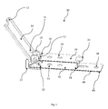
- FIG. 1 is an angled assembled side view of the Multifunction Reversible Clip 10 .
- the Multifunctional Clip is made up of three main parts, the flap 14 , backplate 44 and hooked bracket 24 .
- FIG. 2 is an angled disassembled side view of the Multifunctional Reversible Clip 10 revealing the three main parts the flap 14 , backplate 44 and hooked bracket 24 .
- FIG. 3 is an angled view of the backplate 44 .
- FIG. 4 is an angled assembled side view of the Multifunction Reversible Clip 10 showing the reverse assembly of the three main parts, the flap 14 , backplate 44 and hooked bracket 24 .
- FIG. 5 is an angled side view of the Multifunction Reversible Clip 10 showing the reverse assembly of the of three main parts with the hooked bracket 24 installed on the backplate 44 and dissembled flap 14 .
- FIG. 6 is an angled side view showing the multi hand-help tools options of the flap 14 .
- the compression tab 42 functions as a flat blade screw driver
- the flap lift tab 12 functions as a bottle opener
- the flap 14 can be fashioned into a multi sized wrench.
- the Multifunction Reversible Clip has an angled compression head that relies on leverage and pressure to produce a higher level of retention.
- the compression tab produces pressure on the angled compression head and provides greater retention than found on traditional holster clips.
- the clip, flap and hooked bracket are constructed independently using a single piece of metal or plastic to make each part
- the clip, flap and hooked bracket once constructed are assembled make the multifunctional reversible clip.
- the flap is rotated manually thus providing leverage and pressure to secure the angled compression head.
- the Multifunctional Reversible Clip 10 which consists of a flap lift tab 12 , flap 14 , flap slots 16 , hooked bracket post 18 , upper bracket slot 20 , lower bracket slot 22 , hooked bracket 24 , upper mounting plate 26 , upper mounting hole 28 , lower mounting plate 30 , lower mounting hole 32 , angled compression head 34 , clamping head lift tab 36 , primary mounting hole 38 , primary mounting plate 40 , compression tab 42 , and the backplate 44 .
- the backplate 44 is not limited to but preferably fashioned out of either metal or plastic and is folded, bent or molded to provide the, upper bracket slot 20 , lower bracket slot 22 , upper mounting plate 26 , upper mounting hole 28 , lower mounting plate 30 , lower mounting hole 32 , angled compression head 34 , clamping head lift tab 36 , primary mounting hole 38 , and primary mounting plate 40 .
- the flap 14 is fabricated independently of the backplate 44 and hooked bracket 24 .
- the hooked bracket 24 is fabricated independently of the backplate 44 and flap 14 .
- the flap 14 , backplate 44 and bracket 24 are required for normal assembly of the Multifunctional Reversible Clip 10 as shown in FIG. 1 .
- the hooked bracket 24 is first assembled to the backplate 44 by inserting the hooked bracket posts 18 through lower bracket slots 22 this process is continued until the hooked bracket posts 18 pass through the upper bracket slots 20 .
- the flap 14 is ready for assembly.
- To assemble the flap 14 first rotate the flap 14 so that the compress tab 42 is at a 31 degree angle in relation to the upper mounting plate 26 . By hand manually compress the upper mounting plate 26 and the lower mounting plate 30 . Once compressed there will be a gap between the hooked bracket posts 18 and the upper bracket slots 20 . Align the flap slots 16 with the hooked bracket post 18 . Slide the flap slots 16 through the hooked bracket post 18 until full inserted and release the compressed upper mounting plate 26 and lower mounting plate 30 .
- the Multifunctional Reversible Clip is now in its normal assembled state as shown in FIG. 1 .
- the flap 14 , backplate 44 and compression hooked bracket 24 are required.
- the compression hooked bracket 24 is first assembled to the backplate 44 by inserting the hooked bracket posts 18 through the upper bracket slots 20 this process is continued until the hooked bracket posts 18 pass through the lower bracket slots 22 .
- the flap 14 is ready for assembly.
- To assemble the flap 14 first rotate the flap 14 so that the compression tab 42 is parallel in relation to the lower mounting plate 30 .
- By hand manually compress the upper mounting plate 26 and the lower mounting plate 30 . Once compressed there will be a gap between the hooked bracket posts 18 and the lower bracket slots 22 . Align the flap slots 18 with the hooked bracket post 18 . Slide the flap slots 18 through the hooked bracket post 18 until full inserted and release the compressed upper mounting plate 26 and lower mounting plate 30 .
- the Multifunctional Reversible Clip is now in its reversed assembled state as shown in FIG. 4 .
- the flap 12 can be removed from the backplate 44 and the hooked bracket 24 . Once the flap 14 is removed from the backplate 44 and the hooked bracket 24 it can be used as a multi handheld tool.
- the compression tab 42 functions as a flat blade screw driver and the flap lift tab 12 can be used as a bottle opener. When manufactured the flap 14 can optionally be fashioned in an into a multi sized wrench as shown in FIG. 6 .
- the Multifunctional Reversible Clip may also comprise a flap configured to enable manual removal from the clip without tools, rotation of the flap 180 degrees, and reinstallation, thereby enabling bi-directional clamping ability.
- the Multifunctional Reversible Clip is attached to a firearm holster, knife sheath, pouch or bag to provide better retention.
- Multifunctional Reversible Clip is attached to a holster, knife sheath, bag or pouch it is used much in the same way as a traditional holster, knife sheath pouch or bag clip with the exception of how it provides its retention onto the material where it will be attached.
- the Multifunctional Reversible Clip is placed in a location and the angled compression head is placed around the desired material when it is in its open state.
- the Multifunctional Reversible Clip is considered open when the flap is at an angle greater than 80 degree from the mounting plate.
- the Multifunctional Reversible Clip is considered closed when the flap is at an angle of 5 degrees or less from the mounting plate.
- the Multifunctional Reversible Clip provides its retention when the flap is manually rotated down toward the mounting plate and applies downward pressure to the angled compression head.
- the flap When in the open position the flap may be turned clockwise to increase the level of retention or it may be turned counterclockwise to decrease the level of retention.
- the gap between the angled compression head and the mounting plate decreases, the retention capability of the Multifunctional Reversible Clip increases.
Landscapes
- Engineering & Computer Science (AREA)
- General Engineering & Computer Science (AREA)
- Mechanical Engineering (AREA)
- Supports Or Holders For Household Use (AREA)
Abstract
Description
Claims (9)
Priority Applications (1)
| Application Number | Priority Date | Filing Date | Title |
|---|---|---|---|
| US15/684,931 US10451096B2 (en) | 2017-08-23 | 2017-08-23 | Multifunctional reversible clip |
Applications Claiming Priority (1)
| Application Number | Priority Date | Filing Date | Title |
|---|---|---|---|
| US15/684,931 US10451096B2 (en) | 2017-08-23 | 2017-08-23 | Multifunctional reversible clip |
Publications (2)
| Publication Number | Publication Date |
|---|---|
| US20190063477A1 US20190063477A1 (en) | 2019-02-28 |
| US10451096B2 true US10451096B2 (en) | 2019-10-22 |
Family
ID=65437310
Family Applications (1)
| Application Number | Title | Priority Date | Filing Date |
|---|---|---|---|
| US15/684,931 Active US10451096B2 (en) | 2017-08-23 | 2017-08-23 | Multifunctional reversible clip |
Country Status (1)
| Country | Link |
|---|---|
| US (1) | US10451096B2 (en) |
Families Citing this family (2)
| Publication number | Priority date | Publication date | Assignee | Title |
|---|---|---|---|---|
| CN111713901A (en) * | 2019-03-20 | 2020-09-29 | 卢旭 | Convenient dismounting device and using method thereof |
| US12031358B2 (en) * | 2020-11-10 | 2024-07-09 | David Workman | Portable sliding door securement device |
Citations (9)
| Publication number | Priority date | Publication date | Assignee | Title |
|---|---|---|---|---|
| US2932873A (en) * | 1958-06-09 | 1960-04-19 | Shampaine Company | Clamp |
| US3907182A (en) * | 1973-05-03 | 1975-09-23 | Clyde C Bryant | Receptacle clamp |
| US4085997A (en) * | 1977-03-30 | 1978-04-25 | The Boeing Company | Anodize clamp |
| CA1087148A (en) * | 1977-09-09 | 1980-10-07 | John V. Kostigian | Carpet clip |
| GB2104586A (en) * | 1981-08-05 | 1983-03-09 | James Pert | Clamps |
| US5615851A (en) * | 1995-11-06 | 1997-04-01 | Yazaki Corporation | Wire harness attachment clip |
| US6568644B2 (en) * | 2001-05-25 | 2003-05-27 | Jac Products Inc. | Clamp for a cross bar |
| US20160058168A1 (en) * | 2014-08-29 | 2016-03-03 | Chums, Inc. | Accessory fastening devices and methods |
| US20180119714A1 (en) * | 2016-11-01 | 2018-05-03 | Ty-Flot, Inc. | Locking badge clamp |
-
2017
- 2017-08-23 US US15/684,931 patent/US10451096B2/en active Active
Patent Citations (9)
| Publication number | Priority date | Publication date | Assignee | Title |
|---|---|---|---|---|
| US2932873A (en) * | 1958-06-09 | 1960-04-19 | Shampaine Company | Clamp |
| US3907182A (en) * | 1973-05-03 | 1975-09-23 | Clyde C Bryant | Receptacle clamp |
| US4085997A (en) * | 1977-03-30 | 1978-04-25 | The Boeing Company | Anodize clamp |
| CA1087148A (en) * | 1977-09-09 | 1980-10-07 | John V. Kostigian | Carpet clip |
| GB2104586A (en) * | 1981-08-05 | 1983-03-09 | James Pert | Clamps |
| US5615851A (en) * | 1995-11-06 | 1997-04-01 | Yazaki Corporation | Wire harness attachment clip |
| US6568644B2 (en) * | 2001-05-25 | 2003-05-27 | Jac Products Inc. | Clamp for a cross bar |
| US20160058168A1 (en) * | 2014-08-29 | 2016-03-03 | Chums, Inc. | Accessory fastening devices and methods |
| US20180119714A1 (en) * | 2016-11-01 | 2018-05-03 | Ty-Flot, Inc. | Locking badge clamp |
Also Published As
| Publication number | Publication date |
|---|---|
| US20190063477A1 (en) | 2019-02-28 |
Similar Documents
| Publication | Publication Date | Title |
|---|---|---|
| US6994238B2 (en) | Screw gun holster | |
| US6062449A (en) | Tool belt tool tote | |
| US6594906B1 (en) | Knife with integral gated attachment | |
| US6443342B1 (en) | Tool belt double tool tote | |
| US6561402B2 (en) | Ambidextrous drill holster | |
| US9354004B2 (en) | Charging handle strap | |
| EP3034244B1 (en) | Multipurpose tool | |
| US20040174700A1 (en) | Single body multi-tool device | |
| US7389899B2 (en) | Flashlight holster | |
| WO2019014571A1 (en) | Systems and methods for a 360 degree rotating and detachable double carabiner | |
| US10451096B2 (en) | Multifunctional reversible clip | |
| US10070699B2 (en) | Clasp | |
| US20100044405A1 (en) | Belt mountable holster for holding a power tool | |
| US9777987B2 (en) | Clamping retention clip | |
| US20160311105A1 (en) | Cover removing tool | |
| US20140301672A1 (en) | Clasp | |
| US11229267B2 (en) | Key holder | |
| US20190193249A1 (en) | Clamping system | |
| EP1457132B1 (en) | Baton holder | |
| US20230300231A1 (en) | Apparatus for enabling interchangeable detachable attachment | |
| US20160120282A1 (en) | Clamping Retention Clip | |
| US20050082321A1 (en) | Baton holster | |
| AU2010206091B2 (en) | A Single-Hand Tablet Computer Manipulation Device | |
| US10393479B1 (en) | Holster mounting system | |
| US10226092B1 (en) | Utility clip |
Legal Events
| Date | Code | Title | Description |
|---|---|---|---|
| FEPP | Fee payment procedure |
Free format text: ENTITY STATUS SET TO MICRO (ORIGINAL EVENT CODE: MICR); ENTITY STATUS OF PATENT OWNER: SMALL ENTITY Free format text: ENTITY STATUS SET TO SMALL (ORIGINAL EVENT CODE: SMAL); ENTITY STATUS OF PATENT OWNER: SMALL ENTITY Free format text: ENTITY STATUS SET TO MICRO (ORIGINAL EVENT CODE: MICR); ENTITY STATUS OF PATENT OWNER: MICROENTITY Free format text: ENTITY STATUS SET TO SMALL (ORIGINAL EVENT CODE: SMAL); ENTITY STATUS OF PATENT OWNER: MICROENTITY |
|
| STPP | Information on status: patent application and granting procedure in general |
Free format text: RESPONSE TO NON-FINAL OFFICE ACTION ENTERED AND FORWARDED TO EXAMINER |
|
| STPP | Information on status: patent application and granting procedure in general |
Free format text: NOTICE OF ALLOWANCE MAILED -- APPLICATION RECEIVED IN OFFICE OF PUBLICATIONS |
|
| STCF | Information on status: patent grant |
Free format text: PATENTED CASE |
|
| AS | Assignment |
Owner name: ULTICLIP, LLC, FLORIDA Free format text: ASSIGNMENT OF ASSIGNORS INTEREST;ASSIGNOR:DARBY, RANDALL LYNN;REEL/FRAME:053386/0615 Effective date: 20200803 |
|
| MAFP | Maintenance fee payment |
Free format text: PAYMENT OF MAINTENANCE FEE, 4TH YR, SMALL ENTITY (ORIGINAL EVENT CODE: M2551); ENTITY STATUS OF PATENT OWNER: SMALL ENTITY Year of fee payment: 4 |