US10450643B2 - Material joining - Google Patents
Material joining Download PDFInfo
- Publication number
- US10450643B2 US10450643B2 US15/209,550 US201615209550A US10450643B2 US 10450643 B2 US10450643 B2 US 10450643B2 US 201615209550 A US201615209550 A US 201615209550A US 10450643 B2 US10450643 B2 US 10450643B2
- Authority
- US
- United States
- Prior art keywords
- surface features
- substrate
- bmg
- interlock surface
- bmg material
- Prior art date
- Legal status (The legal status is an assumption and is not a legal conclusion. Google has not performed a legal analysis and makes no representation as to the accuracy of the status listed.)
- Active, expires
Links
- 239000000463 material Substances 0.000 title claims abstract description 134
- 238000005304 joining Methods 0.000 title claims abstract description 35
- 239000000758 substrate Substances 0.000 claims abstract description 142
- 238000000034 method Methods 0.000 claims abstract description 38
- 238000000151 deposition Methods 0.000 claims abstract description 17
- 238000002425 crystallisation Methods 0.000 claims abstract description 13
- 230000008025 crystallization Effects 0.000 claims abstract description 13
- 239000005300 metallic glass Substances 0.000 claims abstract description 11
- 230000009477 glass transition Effects 0.000 claims description 8
- 238000010288 cold spraying Methods 0.000 claims description 4
- 238000000748 compression moulding Methods 0.000 claims description 3
- 238000007731 hot pressing Methods 0.000 claims description 3
- 238000005096 rolling process Methods 0.000 claims description 3
- 238000007751 thermal spraying Methods 0.000 claims description 3
- 238000010104 thermoplastic forming Methods 0.000 claims description 3
- 238000005253 cladding Methods 0.000 description 11
- 230000008901 benefit Effects 0.000 description 4
- 238000005260 corrosion Methods 0.000 description 4
- 230000007797 corrosion Effects 0.000 description 4
- 229910052751 metal Inorganic materials 0.000 description 4
- 239000002184 metal Substances 0.000 description 4
- 229920000642 polymer Polymers 0.000 description 4
- RTAQQCXQSZGOHL-UHFFFAOYSA-N Titanium Chemical compound [Ti] RTAQQCXQSZGOHL-UHFFFAOYSA-N 0.000 description 3
- 229910052782 aluminium Inorganic materials 0.000 description 3
- XAGFODPZIPBFFR-UHFFFAOYSA-N aluminium Chemical compound [Al] XAGFODPZIPBFFR-UHFFFAOYSA-N 0.000 description 3
- 239000000919 ceramic Substances 0.000 description 3
- 239000002131 composite material Substances 0.000 description 3
- 150000002739 metals Chemical class 0.000 description 3
- 239000010936 titanium Substances 0.000 description 3
- 229910052719 titanium Inorganic materials 0.000 description 3
- 230000008021 deposition Effects 0.000 description 2
- 238000005137 deposition process Methods 0.000 description 2
- -1 e.g. Substances 0.000 description 2
- 239000011521 glass Substances 0.000 description 2
- 238000003754 machining Methods 0.000 description 2
- 239000002245 particle Substances 0.000 description 2
- 239000004033 plastic Substances 0.000 description 2
- 229920003023 plastic Polymers 0.000 description 2
- 239000000126 substance Substances 0.000 description 2
- PNEYBMLMFCGWSK-UHFFFAOYSA-N Alumina Chemical group [O-2].[O-2].[O-2].[Al+3].[Al+3] PNEYBMLMFCGWSK-UHFFFAOYSA-N 0.000 description 1
- 229910000831 Steel Inorganic materials 0.000 description 1
- 239000000654 additive Substances 0.000 description 1
- 230000000996 additive effect Effects 0.000 description 1
- 239000000853 adhesive Substances 0.000 description 1
- 230000001070 adhesive effect Effects 0.000 description 1
- 239000000956 alloy Substances 0.000 description 1
- 229910045601 alloy Inorganic materials 0.000 description 1
- 239000001996 bearing alloy Substances 0.000 description 1
- 238000005422 blasting Methods 0.000 description 1
- 238000003486 chemical etching Methods 0.000 description 1
- 238000006243 chemical reaction Methods 0.000 description 1
- 230000006835 compression Effects 0.000 description 1
- 238000007906 compression Methods 0.000 description 1
- 238000009760 electrical discharge machining Methods 0.000 description 1
- 238000000227 grinding Methods 0.000 description 1
- 238000004519 manufacturing process Methods 0.000 description 1
- 238000012986 modification Methods 0.000 description 1
- 230000004048 modification Effects 0.000 description 1
- TWNQGVIAIRXVLR-UHFFFAOYSA-N oxo(oxoalumanyloxy)alumane Chemical compound O=[Al]O[Al]=O TWNQGVIAIRXVLR-UHFFFAOYSA-N 0.000 description 1
- 229920013657 polymer matrix composite Polymers 0.000 description 1
- 239000011160 polymer matrix composite Substances 0.000 description 1
- 239000007921 spray Substances 0.000 description 1
- 239000010959 steel Substances 0.000 description 1
- 238000003860 storage Methods 0.000 description 1
- 210000005239 tubule Anatomy 0.000 description 1
- 238000010792 warming Methods 0.000 description 1
Images


Classifications
-
- C—CHEMISTRY; METALLURGY
- C23—COATING METALLIC MATERIAL; COATING MATERIAL WITH METALLIC MATERIAL; CHEMICAL SURFACE TREATMENT; DIFFUSION TREATMENT OF METALLIC MATERIAL; COATING BY VACUUM EVAPORATION, BY SPUTTERING, BY ION IMPLANTATION OR BY CHEMICAL VAPOUR DEPOSITION, IN GENERAL; INHIBITING CORROSION OF METALLIC MATERIAL OR INCRUSTATION IN GENERAL
- C23C—COATING METALLIC MATERIAL; COATING MATERIAL WITH METALLIC MATERIAL; SURFACE TREATMENT OF METALLIC MATERIAL BY DIFFUSION INTO THE SURFACE, BY CHEMICAL CONVERSION OR SUBSTITUTION; COATING BY VACUUM EVAPORATION, BY SPUTTERING, BY ION IMPLANTATION OR BY CHEMICAL VAPOUR DEPOSITION, IN GENERAL
- C23C4/00—Coating by spraying the coating material in the molten state, e.g. by flame, plasma or electric discharge
- C23C4/12—Coating by spraying the coating material in the molten state, e.g. by flame, plasma or electric discharge characterised by the method of spraying
-
- B—PERFORMING OPERATIONS; TRANSPORTING
- B23—MACHINE TOOLS; METAL-WORKING NOT OTHERWISE PROVIDED FOR
- B23K—SOLDERING OR UNSOLDERING; WELDING; CLADDING OR PLATING BY SOLDERING OR WELDING; CUTTING BY APPLYING HEAT LOCALLY, e.g. FLAME CUTTING; WORKING BY LASER BEAM
- B23K20/00—Non-electric welding by applying impact or other pressure, with or without the application of heat, e.g. cladding or plating
- B23K20/16—Non-electric welding by applying impact or other pressure, with or without the application of heat, e.g. cladding or plating with interposition of special material to facilitate connection of the parts, e.g. material for absorbing or producing gas
-
- B—PERFORMING OPERATIONS; TRANSPORTING
- B23—MACHINE TOOLS; METAL-WORKING NOT OTHERWISE PROVIDED FOR
- B23K—SOLDERING OR UNSOLDERING; WELDING; CLADDING OR PLATING BY SOLDERING OR WELDING; CUTTING BY APPLYING HEAT LOCALLY, e.g. FLAME CUTTING; WORKING BY LASER BEAM
- B23K35/00—Rods, electrodes, materials, or media, for use in soldering, welding, or cutting
-
- B—PERFORMING OPERATIONS; TRANSPORTING
- B29—WORKING OF PLASTICS; WORKING OF SUBSTANCES IN A PLASTIC STATE IN GENERAL
- B29C—SHAPING OR JOINING OF PLASTICS; SHAPING OF MATERIAL IN A PLASTIC STATE, NOT OTHERWISE PROVIDED FOR; AFTER-TREATMENT OF THE SHAPED PRODUCTS, e.g. REPAIRING
- B29C65/00—Joining or sealing of preformed parts, e.g. welding of plastics materials; Apparatus therefor
- B29C65/02—Joining or sealing of preformed parts, e.g. welding of plastics materials; Apparatus therefor by heating, with or without pressure
-
- B—PERFORMING OPERATIONS; TRANSPORTING
- B29—WORKING OF PLASTICS; WORKING OF SUBSTANCES IN A PLASTIC STATE IN GENERAL
- B29C—SHAPING OR JOINING OF PLASTICS; SHAPING OF MATERIAL IN A PLASTIC STATE, NOT OTHERWISE PROVIDED FOR; AFTER-TREATMENT OF THE SHAPED PRODUCTS, e.g. REPAIRING
- B29C65/00—Joining or sealing of preformed parts, e.g. welding of plastics materials; Apparatus therefor
- B29C65/70—Joining or sealing of preformed parts, e.g. welding of plastics materials; Apparatus therefor by moulding
-
- C—CHEMISTRY; METALLURGY
- C22—METALLURGY; FERROUS OR NON-FERROUS ALLOYS; TREATMENT OF ALLOYS OR NON-FERROUS METALS
- C22C—ALLOYS
- C22C45/00—Amorphous alloys
-
- C—CHEMISTRY; METALLURGY
- C23—COATING METALLIC MATERIAL; COATING MATERIAL WITH METALLIC MATERIAL; CHEMICAL SURFACE TREATMENT; DIFFUSION TREATMENT OF METALLIC MATERIAL; COATING BY VACUUM EVAPORATION, BY SPUTTERING, BY ION IMPLANTATION OR BY CHEMICAL VAPOUR DEPOSITION, IN GENERAL; INHIBITING CORROSION OF METALLIC MATERIAL OR INCRUSTATION IN GENERAL
- C23C—COATING METALLIC MATERIAL; COATING MATERIAL WITH METALLIC MATERIAL; SURFACE TREATMENT OF METALLIC MATERIAL BY DIFFUSION INTO THE SURFACE, BY CHEMICAL CONVERSION OR SUBSTITUTION; COATING BY VACUUM EVAPORATION, BY SPUTTERING, BY ION IMPLANTATION OR BY CHEMICAL VAPOUR DEPOSITION, IN GENERAL
- C23C14/00—Coating by vacuum evaporation, by sputtering or by ion implantation of the coating forming material
- C23C14/22—Coating by vacuum evaporation, by sputtering or by ion implantation of the coating forming material characterised by the process of coating
- C23C14/56—Apparatus specially adapted for continuous coating; Arrangements for maintaining the vacuum, e.g. vacuum locks
- C23C14/568—Transferring the substrates through a series of coating stations
-
- C—CHEMISTRY; METALLURGY
- C23—COATING METALLIC MATERIAL; COATING MATERIAL WITH METALLIC MATERIAL; CHEMICAL SURFACE TREATMENT; DIFFUSION TREATMENT OF METALLIC MATERIAL; COATING BY VACUUM EVAPORATION, BY SPUTTERING, BY ION IMPLANTATION OR BY CHEMICAL VAPOUR DEPOSITION, IN GENERAL; INHIBITING CORROSION OF METALLIC MATERIAL OR INCRUSTATION IN GENERAL
- C23C—COATING METALLIC MATERIAL; COATING MATERIAL WITH METALLIC MATERIAL; SURFACE TREATMENT OF METALLIC MATERIAL BY DIFFUSION INTO THE SURFACE, BY CHEMICAL CONVERSION OR SUBSTITUTION; COATING BY VACUUM EVAPORATION, BY SPUTTERING, BY ION IMPLANTATION OR BY CHEMICAL VAPOUR DEPOSITION, IN GENERAL
- C23C24/00—Coating starting from inorganic powder
- C23C24/02—Coating starting from inorganic powder by application of pressure only
- C23C24/04—Impact or kinetic deposition of particles
-
- C—CHEMISTRY; METALLURGY
- C23—COATING METALLIC MATERIAL; COATING MATERIAL WITH METALLIC MATERIAL; CHEMICAL SURFACE TREATMENT; DIFFUSION TREATMENT OF METALLIC MATERIAL; COATING BY VACUUM EVAPORATION, BY SPUTTERING, BY ION IMPLANTATION OR BY CHEMICAL VAPOUR DEPOSITION, IN GENERAL; INHIBITING CORROSION OF METALLIC MATERIAL OR INCRUSTATION IN GENERAL
- C23C—COATING METALLIC MATERIAL; COATING MATERIAL WITH METALLIC MATERIAL; SURFACE TREATMENT OF METALLIC MATERIAL BY DIFFUSION INTO THE SURFACE, BY CHEMICAL CONVERSION OR SUBSTITUTION; COATING BY VACUUM EVAPORATION, BY SPUTTERING, BY ION IMPLANTATION OR BY CHEMICAL VAPOUR DEPOSITION, IN GENERAL
- C23C24/00—Coating starting from inorganic powder
- C23C24/08—Coating starting from inorganic powder by application of heat or pressure and heat
-
- C—CHEMISTRY; METALLURGY
- C23—COATING METALLIC MATERIAL; COATING MATERIAL WITH METALLIC MATERIAL; CHEMICAL SURFACE TREATMENT; DIFFUSION TREATMENT OF METALLIC MATERIAL; COATING BY VACUUM EVAPORATION, BY SPUTTERING, BY ION IMPLANTATION OR BY CHEMICAL VAPOUR DEPOSITION, IN GENERAL; INHIBITING CORROSION OF METALLIC MATERIAL OR INCRUSTATION IN GENERAL
- C23C—COATING METALLIC MATERIAL; COATING MATERIAL WITH METALLIC MATERIAL; SURFACE TREATMENT OF METALLIC MATERIAL BY DIFFUSION INTO THE SURFACE, BY CHEMICAL CONVERSION OR SUBSTITUTION; COATING BY VACUUM EVAPORATION, BY SPUTTERING, BY ION IMPLANTATION OR BY CHEMICAL VAPOUR DEPOSITION, IN GENERAL
- C23C4/00—Coating by spraying the coating material in the molten state, e.g. by flame, plasma or electric discharge
- C23C4/02—Pretreatment of the material to be coated, e.g. for coating on selected surface areas
-
- C—CHEMISTRY; METALLURGY
- C23—COATING METALLIC MATERIAL; COATING MATERIAL WITH METALLIC MATERIAL; CHEMICAL SURFACE TREATMENT; DIFFUSION TREATMENT OF METALLIC MATERIAL; COATING BY VACUUM EVAPORATION, BY SPUTTERING, BY ION IMPLANTATION OR BY CHEMICAL VAPOUR DEPOSITION, IN GENERAL; INHIBITING CORROSION OF METALLIC MATERIAL OR INCRUSTATION IN GENERAL
- C23C—COATING METALLIC MATERIAL; COATING MATERIAL WITH METALLIC MATERIAL; SURFACE TREATMENT OF METALLIC MATERIAL BY DIFFUSION INTO THE SURFACE, BY CHEMICAL CONVERSION OR SUBSTITUTION; COATING BY VACUUM EVAPORATION, BY SPUTTERING, BY ION IMPLANTATION OR BY CHEMICAL VAPOUR DEPOSITION, IN GENERAL
- C23C4/00—Coating by spraying the coating material in the molten state, e.g. by flame, plasma or electric discharge
- C23C4/04—Coating by spraying the coating material in the molten state, e.g. by flame, plasma or electric discharge characterised by the coating material
- C23C4/06—Metallic material
-
- C—CHEMISTRY; METALLURGY
- C23—COATING METALLIC MATERIAL; COATING MATERIAL WITH METALLIC MATERIAL; CHEMICAL SURFACE TREATMENT; DIFFUSION TREATMENT OF METALLIC MATERIAL; COATING BY VACUUM EVAPORATION, BY SPUTTERING, BY ION IMPLANTATION OR BY CHEMICAL VAPOUR DEPOSITION, IN GENERAL; INHIBITING CORROSION OF METALLIC MATERIAL OR INCRUSTATION IN GENERAL
- C23C—COATING METALLIC MATERIAL; COATING MATERIAL WITH METALLIC MATERIAL; SURFACE TREATMENT OF METALLIC MATERIAL BY DIFFUSION INTO THE SURFACE, BY CHEMICAL CONVERSION OR SUBSTITUTION; COATING BY VACUUM EVAPORATION, BY SPUTTERING, BY ION IMPLANTATION OR BY CHEMICAL VAPOUR DEPOSITION, IN GENERAL
- C23C4/00—Coating by spraying the coating material in the molten state, e.g. by flame, plasma or electric discharge
- C23C4/18—After-treatment
-
- F—MECHANICAL ENGINEERING; LIGHTING; HEATING; WEAPONS; BLASTING
- F16—ENGINEERING ELEMENTS AND UNITS; GENERAL MEASURES FOR PRODUCING AND MAINTAINING EFFECTIVE FUNCTIONING OF MACHINES OR INSTALLATIONS; THERMAL INSULATION IN GENERAL
- F16B—DEVICES FOR FASTENING OR SECURING CONSTRUCTIONAL ELEMENTS OR MACHINE PARTS TOGETHER, e.g. NAILS, BOLTS, CIRCLIPS, CLAMPS, CLIPS OR WEDGES; JOINTS OR JOINTING
- F16B11/00—Connecting constructional elements or machine parts by sticking or pressing them together, e.g. cold pressure welding
-
- F—MECHANICAL ENGINEERING; LIGHTING; HEATING; WEAPONS; BLASTING
- F16—ENGINEERING ELEMENTS AND UNITS; GENERAL MEASURES FOR PRODUCING AND MAINTAINING EFFECTIVE FUNCTIONING OF MACHINES OR INSTALLATIONS; THERMAL INSULATION IN GENERAL
- F16B—DEVICES FOR FASTENING OR SECURING CONSTRUCTIONAL ELEMENTS OR MACHINE PARTS TOGETHER, e.g. NAILS, BOLTS, CIRCLIPS, CLAMPS, CLIPS OR WEDGES; JOINTS OR JOINTING
- F16B5/00—Joining sheets or plates, e.g. panels, to one another or to strips or bars parallel to them
- F16B5/07—Joining sheets or plates, e.g. panels, to one another or to strips or bars parallel to them by means of multiple interengaging protrusions on the surfaces, e.g. hooks, coils
Definitions
- the present disclosure relates to joining techniques for materials such as metals, glasses, ceramics, polymers, composites, or combinations thereof.
- BMG's Bulk Metallic Glasses
- BMG's are an emerging class of engineering material that can be made stronger than steel, have corrosion resistance, and can have extremely high elastic limits.
- One limitation that has limited the applications in which BMG's can be used is that known processing constraints have limited at least one dimension of a given BMG component to less than about 30-40 mm (1.2-1.5 inches).
- BMG's offer a unique processability in that they can be thermoplastically formed, similar to plastics.
- a method of joining includes bringing a bulk metallic glass (BMG) material to a temperature lower than the crystallization temperature of the BMG material and depositing the BMG material onto a first substrate with interlock surface features such that the BMG material interlocks with the interlock surface features of the substrate.
- the method includes joining a second substrate to the BMG material, wherein the second substrate includes interlock surface features such that the BMG material interlocks with the interlock surface features of both the first and second substrates, joining the first and second substrates together to produce a fully amorphous joint between the first and second substrates.
- the method can include forming the interlock surface features on a surface of at least one of the first or second substrates. Forming the interlock surface features can include forming interlock surface features with receptacles for BMG material that narrow in a direction going deeper within the substrate.
- Forming the interlock surface features can include forming interlock surface features with receptacles for BMG material that form a repeating pattern of substantially identical triangular receptacles. It is also contemplated that forming the interlock surface features can include forming interlock surface features with receptacles for BMG material that form an alternating pattern of two sets of different triangular receptacles.
- forming the interlock surface features can include forming interlock surface features with receptacles for BMG material that form a repeating pattern of substantially identical truncated triangular receptacles with truncated triangular teeth separating each respective adjacent pair of the receptacles.
- forming the interlock surface features can include forming interlock surface features with receptacles for BMG material that widen in a direction going deeper within the substrate. Forming the interlock surface features includes forming the receptacles for BMG material between teeth that neck down in a direction going deeper within the substrate, wherein each tooth is symmetrical with respect to neighboring ones of the receptacles.
- the interlock surface features can include at least one of anodized aluminum or titanium.
- Depositing the BMG material can include at least one of thermoplastic forming, rolling, compression molding, hot pressing, autoclaving, thermal spraying, or cold spraying the BMG material onto the substrate such that the BMG material interlocks with the interlocking surface features of the substrate.
- Bringing the BMG material to a temperature lower than the crystallization temperature of the BMG material can include bringing a BMG material to a temperature greater than or equal to the glass transition temperature of the BMG material and lower than the crystallization temperature of the BMG material.
- the method can include depositing a portion of the BMG material onto the second substrate such that the portion of the BMG material interlocks with the interlock surface features of the second substrate prior to joining the first and second substrates.
- Joining the first and second substrates can include forming a BMG to BMG bond between the portion of the BMG material deposited on the second substrate, and the BMG material deposited on the first substrate.
- a system includes a first substrate joined to a second substrate by a BMG material. At least one of the first or second substrates includes interlock surface features. The BMG material interlocks with the interlock surface features. The BMG material can form a layer between the first and second substrates that is less than or equal to 2.0 mm thick.
- the interlock surface features can include receptacles in the substrate with BMG material therein, wherein the receptacles narrow in a direction going deeper within the substrate.
- the interlock surface features can include receptacles for BMG material that form a repeating pattern of substantially identical triangular receptacles. It is also contemplated that the interlock surface features can include receptacles for BMG material that form an alternating pattern of two sets of different triangular receptacles.
- the interlock surface features can include receptacles in the substrate with BMG material therein, wherein the receptacles widen in a direction going deeper within the substrate.
- the receptacles for BMG material can be between teeth that neck down in a direction going deeper within the substrate, wherein each tooth is symmetrical with respect to neighboring ones of the receptacles.
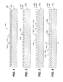
- FIGS. 1-4 are schematic cross-sectional side elevation views of four exemplary embodiments of substrates constructed in accordance with the present disclosure, showing four different respective interlock surface features;
- FIGS. 5-8 are schematic cross-sectional side elevation views of the substrates of FIGS. 1-4 , respectively, showing a Bulk Metallic Glass (BMG) material interlocking with the interlock surface features of a first respective substrate; and
- BMG Bulk Metallic Glass
- FIGS. 9-12 are schematic cross-sectional side elevation views of the substrates of FIGS. 1-4 , respectively, showing a Bulk Metallic Glass (BMG) material interlocking with the interlock surface features of a first respective substrate and of a second respective substrate, joining the first and second respective substrates together.
- BMG Bulk Metallic Glass
- FIG. 1 a partial view of an exemplary embodiment of a system in accordance with the disclosure is shown in FIG. 1 and is designated generally by reference character 100 .
- FIGS. 2-12 Other embodiments of systems in accordance with the disclosure, or aspects thereof, are provided in FIGS. 2-12 , as will be described.
- the systems and methods described herein can be used to join substrates together to produce a fully amorphous interface for material joining, with the advantageous properties of Bulk Metallic Glass (BMG) materials in the joining process and in the resulting system or structure.
- BMG Bulk Metallic Glass
- Cladding system 100 includes a first substrate 102 of a material such as a metal, glass, ceramic, polymer, composite, or any other suitable type of material.
- Substrate 102 is prepared for joining with interlock surface features 104 on a surface thereof.
- a BMG material 106 is joined to substrate 102 , as shown in FIG. 5 .
- the BMG material 106 interlocks with the interlock surface features 104 of the substrate 102 , e.g., for a mechanical interlocking engagement.
- FIG. 1 shows substrate 102 prior to cladding 106 being joined thereto
- FIG. 5 shows cladding system 100 after substrate 102 and cladding 106 have been joined.
- interlock surface features 104 include receptacles 108 in the substrate with BMG material 106 therein, e.g. receptacles 108 are the troughs between the peaks 110 of interlock surface features 104 .
- receptacles 108 narrow in a direction going deeper within the substrate 102 .
- the interlock surface features 104 with receptacles for BMG material form a repeating pattern of substantially identical triangular receptacles 108 .
- an alternating pattern of two sets of different triangular receptacles 208 and 209 can be used, such as in interlock surface features 204 of cladding system 200 of FIGS. 2 and 6 , which includes a substrate 102 and cladding 106 much as described above with respect to FIGS. 1 and 5 .
- Interlock surface features 304 include receptacles that form a repeating pattern of substantially identical truncated triangular receptacles 308 with truncated triangular peeks or teeth 310 separating each respective adjacent pair of the receptacles 308 .
- cladding system 400 has a substrate 402 that includes interlock surface features 404 with receptacles 408 that widen in a direction going deeper within the substrate 402 .
- Each tooth 410 narrows down in a direction going deeper within the substrate 402 and is symmetrical with respect to neighboring ones of the receptacles 408 , i.e., each tooth 410 is symmetrical across a respective tooth axis A half way between the two adjacent receptacles 408 as indicated in FIG. 4 .
- receptacles that have a uniform dimension going deeper within the substrate, e.g., that neither widen nor narrow, can be used, similar to the truncated triangle pattern in FIG. 3 , but more rectangular.
- Cladding 406 is joined to substrate 402 much as described above with respect to FIGS. 1 and 5 .
- any other suitable pattern can be used for the interlock surface features without departing from the scope of this disclosure.
- the substrates 102 , 202 , 302 , and 402 are each joined to a respective second substrate 103 , 203 , 303 , and 403 by the respective BMG material 106 , 206 , 306 , and 406 , as shown in FIGS. 9 - 12 , respectively.
- the BMG materials 106 , 206 , 306 , and 406 interlock with the interlock surface features of both the first and second substrates, and each BMG material forms a layer between the respective first and second substrates that is less than or equal to a typical thickness of 2.0 mm thick, but could be up to 10 mm thick or more, if the particular BMG material and deposition process permit. This thickness, t, is shown in FIGS.
- first and second substrates are configured with matching interlock surface features, however, those skilled in the art will readily appreciate that mismatched interlock surface features can also be used for a first and second substrate without departing from the scope of this disclosure.
- interlocking features described above are examples and that any other suitable interlocking features can be used or formed, e.g., by methods such as grit blasting, laser processing, electrical discharge machining (EDM), mechanical grinding, chemical etching, or the like.
- EDM electrical discharge machining
- a method of forming a bulk metallic glass (BMG) cladding includes bringing a BMG material to a temperature lower than the crystallization temperature of the BMG material, and at least in some embodiments greater than or equal to the glass transition temperature of the BMG material and lower than the crystallization temperature of the BMG material.
- the BMG material can be placed in contact with the substrate with the BMG at room temperature and then the BMG can be heated up to the glass transition temperature (T g ) in order to thermoplastically form the BMG material into the interlock surface features of the substrate. This could be done in a hot press or an autoclave, for example.
- T g glass transition temperature
- the BMG material need not necessarily be required to be above the glass transition temperature during the initial stages of depositing.
- the energy associated with accelerating particles of the BMG material to the substrate may be transformed into heat upon impact (so the particles of BMG material are not above Tg until impact).
- the method also includes depositing the BMG material onto a substrate, e.g., substrate 102 , 202 , 302 , and 402 , with interlock surface features, e.g., interlock surface features 104 , 204 , 304 , and 404 , such that the BMG material interlocks with the interlock surface features of the substrate.
- the method also includes joining a second substrate, e.g., substrate 103 , 203 , 303 , and 403 , to the BMG material, wherein the second substrate includes interlock surface features such that the BMG material interlocks with the interlock surface features of both the first and second substrates, joining the first and second substrates together to produce a fully amorphous joint between the first and second substrates.
- the method can include depositing a portion of the BMG material onto the second substrate such that the portion of the BMG material interlocks with the interlock surface features of the second substrate prior to joining the first and second substrates. For example, this could be done by forming two cladded substrates 102 as shown in FIG. 5 as the first and second substrates. Joining the first and second substrates can include forming a BMG to BMG bond between the portion of the BMG material deposited on the second substrate, and the BMG material deposited on the first substrate.
- the method can include forming the interlock surface features on a surface of at least one of the first or second substrates, e.g., prior to depositing the BMG material onto the substrate.
- anodic aluminum oxide structures can be formed on aluminum-bearing alloys to form interlock surface features with narrow, uniform tubule type structures.
- the interlock surface features can also be performed using chemical means or any other suitable technique.
- the interlock surface features can be formed of the same or different material than the substrate, and can be formed through any suitable methods such as chemical reaction(s), deposition/additive processes, and/or subtractive machining type operations.
- the technique for forming the interlock surface features can be selected on an application by application basis to provide the desired BMG performance.
- the oxide could provide the interlock features, but also may electrically and chemically isolate the substrate from the clad BMG material which could be important for corrosion applications.
- the surface interlock features may already be present in a substrate, without a specific need to form them.
- a composite material is used for the substrate, a rough surface of a polymer matrix composite may provide sufficient repeating surface features to provide the interlock surface features used for interlocking with the BMG material.
- the interlock surface features can include at least one of anodized aluminum or titanium.
- Depositing the BMG material can include any suitable process such as at least one of thermoplastic forming, rolling, compression molding, autoclaving, cold spraying, thermal spraying, or hot pressing the BMG material onto the substrate such that the BMG material interlocks with the interlocking surface features of the substrate. Any other suitable deposition process or combination of processes can be used. For example, if a sheet of stock BMG is used, it can be brought to within the temperature range described above, and can then be rolled, compression molded, hot pressed, vacuum formed, autoclaved, or formed using any suitable plastic forming process, onto the substrate so that the BMG material flows into and interlocks with the interlock surface features mechanically.
- any suitable deposition process or combination of processes can be used. For example, if a sheet of stock BMG is used, it can be brought to within the temperature range described above, and can then be rolled, compression molded, hot pressed, vacuum formed, autoclaved, or formed using any suitable plastic forming process, onto the substrate so that the BMG material flows into and
- the BMG can be cold sprayed or thermal sprayed onto the substrate such that the BMG material interlocks with the interlocking surface features, e.g., wherein the BMG material is delivered to the substrate with the BMG material within the temperature range described above. It is also contemplated that the initial stage of depositing does not actually include flowing BMG material into the interlocking features, which flowing may occur after the initial deposition. For example, BMG material can be deposited onto a substrate up to a desired thickness via a process like cold spray, and subsequently the BMG material could be heated and rolled to provide the flowing into the interlock surface features.
- the BMG material cools to a temperature below the glass transition temperature (T g ) after joining to the first substrate but before joining to the second substrate, the BMG material should be brought back to a temperature above the glass transition temperature (T g ) and below the crystallization temperature (T x ) for joining to the second substrate.
- BMG clad layers as described herein can be used in any suitable application without departing from the scope of this disclosure.
- BMG materials can offer significant benefits in terms of corrosion resistance, elastic storage modulus and ease of forming complex shapes. For example, direct replacement of titanium with a material that can be processed like a polymer, but has properties significantly better than most metallic engineering alloys, would offer a significant cost savings in manufacturing and machining of complex geometries.
- BMG materials as described herein to join two substrates can replace braze joints, welds, and polymeric adhesives in joining materials, e.g. joining two dissimilar materials, wherein the joints are often mechanically weaker than the substrates they are joining.
- a potential advantage of techniques disclosed herein is that high strength and corrosion resistant material can be used to bond may different types of substrates, including polymers, metals, and ceramics.
- the techniques described herein can provide for a highly elastic joint relative to traditional techniques—typical metals have an elastic limit of 0.2%-0.65%, whereas BMG materials can have elastic limits of 2%-3%.
- Another potential advantage of techniques described herein is the ability to re-work joints by warming the joint back up to a temperature between the glass transition temperature (T g ) and the crystallization temperature (T x ).
Landscapes
- Chemical & Material Sciences (AREA)
- Engineering & Computer Science (AREA)
- Mechanical Engineering (AREA)
- Materials Engineering (AREA)
- Metallurgy (AREA)
- Organic Chemistry (AREA)
- Chemical Kinetics & Catalysis (AREA)
- Physics & Mathematics (AREA)
- Plasma & Fusion (AREA)
- General Engineering & Computer Science (AREA)
- Pressure Welding/Diffusion-Bonding (AREA)
Abstract
Description
Claims (6)
Priority Applications (2)
| Application Number | Priority Date | Filing Date | Title |
|---|---|---|---|
| US15/209,550 US10450643B2 (en) | 2016-07-13 | 2016-07-13 | Material joining |
| EP17180756.3A EP3269494B1 (en) | 2016-07-13 | 2017-07-11 | Material joining |
Applications Claiming Priority (1)
| Application Number | Priority Date | Filing Date | Title |
|---|---|---|---|
| US15/209,550 US10450643B2 (en) | 2016-07-13 | 2016-07-13 | Material joining |
Publications (2)
| Publication Number | Publication Date |
|---|---|
| US20180016671A1 US20180016671A1 (en) | 2018-01-18 |
| US10450643B2 true US10450643B2 (en) | 2019-10-22 |
Family
ID=59416528
Family Applications (1)
| Application Number | Title | Priority Date | Filing Date |
|---|---|---|---|
| US15/209,550 Active 2036-11-22 US10450643B2 (en) | 2016-07-13 | 2016-07-13 | Material joining |
Country Status (2)
| Country | Link |
|---|---|
| US (1) | US10450643B2 (en) |
| EP (1) | EP3269494B1 (en) |
Cited By (1)
| Publication number | Priority date | Publication date | Assignee | Title |
|---|---|---|---|---|
| US12497974B2 (en) | 2024-05-24 | 2025-12-16 | Rtx Corporation | Cost-effective solid-state deposition of functionally graded titanium hollow fan blade sheath for improved galvanic corrosion resistance |
Families Citing this family (2)
| Publication number | Priority date | Publication date | Assignee | Title |
|---|---|---|---|---|
| CN110732768B (en) * | 2019-09-20 | 2021-10-08 | 华中科技大学 | A method for forming the same/dissimilar metal connection based on amorphous alloys |
| GB202212940D0 (en) * | 2022-09-05 | 2022-10-19 | Tokamak Energy Ltd | Subtractive manufacturing of complex metal structures |
Citations (27)
| Publication number | Priority date | Publication date | Assignee | Title |
|---|---|---|---|---|
| US4102033A (en) | 1977-03-21 | 1978-07-25 | Kawasaki Steel Corporation | Method of producing layer-like clad metal materials |
| US4316573A (en) | 1978-10-02 | 1982-02-23 | Allied Corporation | Homogeneous brazing foils of copper based metallic glasses |
| US5482580A (en) | 1994-06-13 | 1996-01-09 | Amorphous Alloys Corp. | Joining of metals using a bulk amorphous intermediate layer |
| US5558789A (en) | 1994-03-02 | 1996-09-24 | University Of Florida | Method of applying a laser beam creating micro-scale surface structures prior to deposition of film for increased adhesion |
| US5620537A (en) | 1995-04-28 | 1997-04-15 | Rockwell International Corporation | Method of superplastic extrusion |
| US20030024616A1 (en) | 2001-08-02 | 2003-02-06 | Kim Choongnyun Paul | Joining of amorphous metals to other metals utilizing a cast mechanical joint |
| US20070023489A1 (en) | 2000-05-02 | 2007-02-01 | Swiston Albert J Jr | Method of joining components using amorphous brazes and reactive multilayer foil |
| US20070111119A1 (en) | 2005-11-15 | 2007-05-17 | Honeywell International, Inc. | Method for repairing gas turbine engine compressor components |
| WO2007120205A2 (en) | 2005-11-14 | 2007-10-25 | The Regents Of The University Of California | Compositions of corrosion-resistant fe-based amorphous metals suitable for producing thermal spray coatings |
| KR100787929B1 (en) | 2007-02-09 | 2007-12-24 | 한국원자력연구원 | Low Temperature Bonding Method Between Titanium-Copper Dissimilar Metals Using Amorphous Inserts |
| US20080063889A1 (en) | 2006-09-08 | 2008-03-13 | Alan Duckham | Reactive Multilayer Joining WIth Improved Metallization Techniques |
| US20080251164A1 (en) | 2007-04-04 | 2008-10-16 | Boonrat Lohwongwatana | Process for joining materials using bulk metallic glasses |
| US20080261029A1 (en) | 2005-03-11 | 2008-10-23 | Anna Andersson | Non-Stick Metal Product Coated by Pvd with a Hydrophobic Metal Oxide |
| US20100004373A1 (en) | 2008-07-02 | 2010-01-07 | Jingxu Zhu | Compositions and processes for producing durable hydrophobic and/or olephobic surfaces |
| US20110111213A1 (en) | 2008-06-05 | 2011-05-12 | Fachhochschule Kiel | Hydrophobic Coating and Process for Production Thereof |
| US20110287223A1 (en) | 2010-05-24 | 2011-11-24 | Integran Technologies Inc. | Metallic articles with hydrophobic surfaces |
| CA2763153A1 (en) | 2011-01-05 | 2012-07-05 | Korea Atomic Energy Research Institute | Brazing method for joining using amorphous sputtered coating layer as filler and amorphous brazing filler for the brazing method |
| US20130037177A1 (en) | 2011-08-11 | 2013-02-14 | Hon Hai Precision Industry Co., Ltd. | Aluminum-and-amorphous alloy composite and method for manufacturing |
| WO2013048442A1 (en) | 2011-09-30 | 2013-04-04 | Crucible Intellectual Property, Llc | Tamper resistant amorphous alloy joining |
| WO2013058754A1 (en) | 2011-10-20 | 2013-04-25 | Crucible Intellectual Property Llc | Bulk amorphous alloy heat sink |
| WO2013058765A1 (en) * | 2011-10-21 | 2013-04-25 | Apple Inc. | Joining bulk metallic glass sheets using pressurized fluid forming |
| US20140011050A1 (en) | 2012-07-04 | 2014-01-09 | Joseph C. Poole | Bmg parts having greater than critical casting thickness and method for making the same |
| US20140197664A1 (en) | 2013-01-14 | 2014-07-17 | Nanosteel Company, Inc. | Vehicle structural support member reinforced with ultra high strength laminate |
| WO2014200700A1 (en) | 2013-06-12 | 2014-12-18 | United Technologies Corporation | Corrosion resistant hydrophobic coatings and methods of production thereof |
| CN104439677A (en) | 2014-11-19 | 2015-03-25 | 东莞宜安科技股份有限公司 | Method and product for combining amorphous alloy component and non-metallic component |
| US9174415B2 (en) | 2011-08-18 | 2015-11-03 | Shenzhen Byd Auto R&D Company Limited | Composite and preparation method of joining amorphous alloy material to heterogeneous material |
| WO2015198790A1 (en) | 2014-06-26 | 2015-12-30 | 日立金属株式会社 | Nickel-based amorphous alloy ribbon for brazing, and stainless steel joined object using same |
-
2016
- 2016-07-13 US US15/209,550 patent/US10450643B2/en active Active
-
2017
- 2017-07-11 EP EP17180756.3A patent/EP3269494B1/en active Active
Patent Citations (30)
| Publication number | Priority date | Publication date | Assignee | Title |
|---|---|---|---|---|
| US4102033A (en) | 1977-03-21 | 1978-07-25 | Kawasaki Steel Corporation | Method of producing layer-like clad metal materials |
| US4316573A (en) | 1978-10-02 | 1982-02-23 | Allied Corporation | Homogeneous brazing foils of copper based metallic glasses |
| US5558789A (en) | 1994-03-02 | 1996-09-24 | University Of Florida | Method of applying a laser beam creating micro-scale surface structures prior to deposition of film for increased adhesion |
| US5482580A (en) | 1994-06-13 | 1996-01-09 | Amorphous Alloys Corp. | Joining of metals using a bulk amorphous intermediate layer |
| US5620537A (en) | 1995-04-28 | 1997-04-15 | Rockwell International Corporation | Method of superplastic extrusion |
| US20070023489A1 (en) | 2000-05-02 | 2007-02-01 | Swiston Albert J Jr | Method of joining components using amorphous brazes and reactive multilayer foil |
| US20030024616A1 (en) | 2001-08-02 | 2003-02-06 | Kim Choongnyun Paul | Joining of amorphous metals to other metals utilizing a cast mechanical joint |
| US20080261029A1 (en) | 2005-03-11 | 2008-10-23 | Anna Andersson | Non-Stick Metal Product Coated by Pvd with a Hydrophobic Metal Oxide |
| WO2007120205A2 (en) | 2005-11-14 | 2007-10-25 | The Regents Of The University Of California | Compositions of corrosion-resistant fe-based amorphous metals suitable for producing thermal spray coatings |
| US20070111119A1 (en) | 2005-11-15 | 2007-05-17 | Honeywell International, Inc. | Method for repairing gas turbine engine compressor components |
| US20080063889A1 (en) | 2006-09-08 | 2008-03-13 | Alan Duckham | Reactive Multilayer Joining WIth Improved Metallization Techniques |
| KR100787929B1 (en) | 2007-02-09 | 2007-12-24 | 한국원자력연구원 | Low Temperature Bonding Method Between Titanium-Copper Dissimilar Metals Using Amorphous Inserts |
| US20080251164A1 (en) | 2007-04-04 | 2008-10-16 | Boonrat Lohwongwatana | Process for joining materials using bulk metallic glasses |
| WO2008124623A1 (en) | 2007-04-04 | 2008-10-16 | California Institute Of Technology | Process for joining materials using bulk metallic glasses |
| US7947134B2 (en) | 2007-04-04 | 2011-05-24 | California Institute Of Technology | Process for joining materials using bulk metallic glasses |
| US20110111213A1 (en) | 2008-06-05 | 2011-05-12 | Fachhochschule Kiel | Hydrophobic Coating and Process for Production Thereof |
| US20100004373A1 (en) | 2008-07-02 | 2010-01-07 | Jingxu Zhu | Compositions and processes for producing durable hydrophobic and/or olephobic surfaces |
| US20110287223A1 (en) | 2010-05-24 | 2011-11-24 | Integran Technologies Inc. | Metallic articles with hydrophobic surfaces |
| CA2763153A1 (en) | 2011-01-05 | 2012-07-05 | Korea Atomic Energy Research Institute | Brazing method for joining using amorphous sputtered coating layer as filler and amorphous brazing filler for the brazing method |
| US20130037177A1 (en) | 2011-08-11 | 2013-02-14 | Hon Hai Precision Industry Co., Ltd. | Aluminum-and-amorphous alloy composite and method for manufacturing |
| US9174415B2 (en) | 2011-08-18 | 2015-11-03 | Shenzhen Byd Auto R&D Company Limited | Composite and preparation method of joining amorphous alloy material to heterogeneous material |
| WO2013048442A1 (en) | 2011-09-30 | 2013-04-04 | Crucible Intellectual Property, Llc | Tamper resistant amorphous alloy joining |
| WO2013058754A1 (en) | 2011-10-20 | 2013-04-25 | Crucible Intellectual Property Llc | Bulk amorphous alloy heat sink |
| WO2013058765A1 (en) * | 2011-10-21 | 2013-04-25 | Apple Inc. | Joining bulk metallic glass sheets using pressurized fluid forming |
| US20140011050A1 (en) | 2012-07-04 | 2014-01-09 | Joseph C. Poole | Bmg parts having greater than critical casting thickness and method for making the same |
| US20140197664A1 (en) | 2013-01-14 | 2014-07-17 | Nanosteel Company, Inc. | Vehicle structural support member reinforced with ultra high strength laminate |
| WO2014200700A1 (en) | 2013-06-12 | 2014-12-18 | United Technologies Corporation | Corrosion resistant hydrophobic coatings and methods of production thereof |
| WO2015198790A1 (en) | 2014-06-26 | 2015-12-30 | 日立金属株式会社 | Nickel-based amorphous alloy ribbon for brazing, and stainless steel joined object using same |
| CN104439677A (en) | 2014-11-19 | 2015-03-25 | 东莞宜安科技股份有限公司 | Method and product for combining amorphous alloy component and non-metallic component |
| WO2016078099A1 (en) | 2014-11-19 | 2016-05-26 | 东莞宜安科技股份有限公司 | Method for combining amorphous alloy members and nonmetal member, and product thereof |
Non-Patent Citations (3)
| Title |
|---|
| European Office Action dated Nov. 5, 2018, issued during the prosecution of corresponding European Patent Application No. EP 17180756.3 (7 pages). |
| Extended European Search Report dated Apr. 4, 2017, issued during the prosecution of European Patent Application No. EP 16197832.5 (8 pages). |
| Extended European Search Report dated Oct. 17, 2017, issued during the prosecution of corresponding European Patent Application No. EP 17180756.3 (8 pages). |
Cited By (1)
| Publication number | Priority date | Publication date | Assignee | Title |
|---|---|---|---|---|
| US12497974B2 (en) | 2024-05-24 | 2025-12-16 | Rtx Corporation | Cost-effective solid-state deposition of functionally graded titanium hollow fan blade sheath for improved galvanic corrosion resistance |
Also Published As
| Publication number | Publication date |
|---|---|
| EP3269494B1 (en) | 2020-11-25 |
| US20180016671A1 (en) | 2018-01-18 |
| EP3269494A1 (en) | 2018-01-17 |
Similar Documents
| Publication | Publication Date | Title |
|---|---|---|
| KR102111948B1 (en) | Different material joint body and method for manufacturing the same | |
| KR100983960B1 (en) | Joining method of dissimilar metal materials and joining structure thereof | |
| US8397976B2 (en) | Method for cohesively bonding metal to a non-metallic substrate using capacitors | |
| US10450643B2 (en) | Material joining | |
| JP6003108B2 (en) | Joining method and joining part manufacturing method | |
| CN100409995C (en) | A kind of glue welding connection method | |
| US11890788B2 (en) | Methods and process for producing polymer-metal hybrid components bonded by C—O-M bonds | |
| GB2550966A (en) | Joining method using in-situ formed fasteners | |
| KR20180074201A (en) | copper-aluminum connecting members in face-to-face penetration welding process and preparation method thereof | |
| WO2015005130A1 (en) | Conductive member and method for manufacturing conductive member | |
| KR20130132325A (en) | Method for manufacturing target with flange | |
| TWI331550B (en) | A diffusion bonding method for blocks of based bulk metallic glass | |
| CN111344428B (en) | Metal member, method for producing metal member, metal-resin bonded body, and method for producing metal-resin bonded body | |
| JP5597946B2 (en) | Low-temperature metal joining method | |
| JP5473711B2 (en) | Laminated mold for resin molding and method for producing the same | |
| KR102273204B1 (en) | Bonding method of dissimilar sheet with improved bonding and economical efficiency | |
| US5975410A (en) | Process of bonding a metal brush structure to a planar surface of a metal substrate | |
| JP5912038B2 (en) | Die manufacturing method | |
| JPS58141880A (en) | Joining method of sintered hard alloy | |
| KR101039361B1 (en) | Method of manufacturing joints between titanium or titanium alloys exceeding the strength of the base metal under low temperature conditions | |
| KR102635620B1 (en) | Method for low pressure cold bonding of solid lithium to metal substrate | |
| US20170128981A1 (en) | Bulk metallic glass components | |
| CN110238612A (en) | A kind of welding titanium alloy profile and preparation method thereof | |
| KR101431240B1 (en) | Manufacturing method of clad steel sheet | |
| JP3737989B2 (en) | Method of joining members by pulse energization |
Legal Events
| Date | Code | Title | Description |
|---|---|---|---|
| AS | Assignment |
Owner name: HAMILTON SUNDSTRAND CORPORATION, NORTH CAROLINA Free format text: ASSIGNMENT OF ASSIGNORS INTEREST;ASSIGNORS:MAGDEFRAU, NEAL;SHEEDY, PAUL;TULYANI, SONIA;SIGNING DATES FROM 20161207 TO 20161212;REEL/FRAME:041043/0952 |
|
| STPP | Information on status: patent application and granting procedure in general |
Free format text: FINAL REJECTION MAILED |
|
| STPP | Information on status: patent application and granting procedure in general |
Free format text: RESPONSE AFTER FINAL ACTION FORWARDED TO EXAMINER |
|
| STPP | Information on status: patent application and granting procedure in general |
Free format text: NOTICE OF ALLOWANCE MAILED -- APPLICATION RECEIVED IN OFFICE OF PUBLICATIONS |
|
| STPP | Information on status: patent application and granting procedure in general |
Free format text: PUBLICATIONS -- ISSUE FEE PAYMENT RECEIVED |
|
| STCF | Information on status: patent grant |
Free format text: PATENTED CASE |
|
| MAFP | Maintenance fee payment |
Free format text: PAYMENT OF MAINTENANCE FEE, 4TH YEAR, LARGE ENTITY (ORIGINAL EVENT CODE: M1551); ENTITY STATUS OF PATENT OWNER: LARGE ENTITY Year of fee payment: 4 |