US10444765B2 - Vehicle that moves automatically within an environment as well as a system with a vehicle and an external illuminating device - Google Patents

Vehicle that moves automatically within an environment as well as a system with a vehicle and an external illuminating device Download PDF

Info

Publication number
US10444765B2
US10444765B2 US16/002,251 US201816002251A US10444765B2 US 10444765 B2 US10444765 B2 US 10444765B2 US 201816002251 A US201816002251 A US 201816002251A US 10444765 B2 US10444765 B2 US 10444765B2
Authority
US
United States
Prior art keywords
illuminating device
vehicle
environment
controller
control command
Prior art date
Legal status (The legal status is an assumption and is not a legal conclusion. Google has not performed a legal analysis and makes no representation as to the accuracy of the status listed.)
Active
Application number
US16/002,251
Other versions
US20180356834A1 (en
Inventor
David Erkek
Georg Hackert
Gerhard Isenberg
Roman Ortmann
Andreas Schmidt
Current Assignee (The listed assignees may be inaccurate. Google has not performed a legal analysis and makes no representation or warranty as to the accuracy of the list.)
Vorwerk and Co Interholding GmbH
Original Assignee
Vorwerk and Co Interholding GmbH
Priority date (The priority date is an assumption and is not a legal conclusion. Google has not performed a legal analysis and makes no representation as to the accuracy of the date listed.)
Filing date
Publication date
Application filed by Vorwerk and Co Interholding GmbH filed Critical Vorwerk and Co Interholding GmbH
Assigned to VORWERK & CO. INTERHOLDING GMBH reassignment VORWERK & CO. INTERHOLDING GMBH ASSIGNMENT OF ASSIGNORS INTEREST (SEE DOCUMENT FOR DETAILS). Assignors: SCHMIDT, ANDREAS, HACKERT, GEORG, Erkek, David, Isenberg, Gerhard, Ortmann, Roman
Publication of US20180356834A1 publication Critical patent/US20180356834A1/en
Application granted granted Critical
Publication of US10444765B2 publication Critical patent/US10444765B2/en
Active legal-status Critical Current
Anticipated expiration legal-status Critical

Links

Images

Classifications

    • GPHYSICS
    • G05CONTROLLING; REGULATING
    • G05DSYSTEMS FOR CONTROLLING OR REGULATING NON-ELECTRIC VARIABLES
    • G05D1/00Control of position, course, altitude or attitude of land, water, air or space vehicles, e.g. using automatic pilots
    • G05D1/02Control of position or course in two dimensions
    • G05D1/021Control of position or course in two dimensions specially adapted to land vehicles
    • G05D1/0268Control of position or course in two dimensions specially adapted to land vehicles using internal positioning means
    • G05D1/0274Control of position or course in two dimensions specially adapted to land vehicles using internal positioning means using mapping information stored in a memory device
    • HELECTRICITY
    • H05ELECTRIC TECHNIQUES NOT OTHERWISE PROVIDED FOR
    • H05BELECTRIC HEATING; ELECTRIC LIGHT SOURCES NOT OTHERWISE PROVIDED FOR; CIRCUIT ARRANGEMENTS FOR ELECTRIC LIGHT SOURCES, IN GENERAL
    • H05B47/00Circuit arrangements for operating light sources in general, i.e. where the type of light source is not relevant
    • H05B47/10Controlling the light source
    • H05B47/105Controlling the light source in response to determined parameters
    • H05B47/115Controlling the light source in response to determined parameters by determining the presence or movement of objects or living beings
    • AHUMAN NECESSITIES
    • A47FURNITURE; DOMESTIC ARTICLES OR APPLIANCES; COFFEE MILLS; SPICE MILLS; SUCTION CLEANERS IN GENERAL
    • A47LDOMESTIC WASHING OR CLEANING; SUCTION CLEANERS IN GENERAL
    • A47L9/00Details or accessories of suction cleaners, e.g. mechanical means for controlling the suction or for effecting pulsating action; Storing devices specially adapted to suction cleaners or parts thereof; Carrying-vehicles specially adapted for suction cleaners
    • A47L9/009Carrying-vehicles; Arrangements of trollies or wheels; Means for avoiding mechanical obstacles
    • AHUMAN NECESSITIES
    • A47FURNITURE; DOMESTIC ARTICLES OR APPLIANCES; COFFEE MILLS; SPICE MILLS; SUCTION CLEANERS IN GENERAL
    • A47LDOMESTIC WASHING OR CLEANING; SUCTION CLEANERS IN GENERAL
    • A47L9/00Details or accessories of suction cleaners, e.g. mechanical means for controlling the suction or for effecting pulsating action; Storing devices specially adapted to suction cleaners or parts thereof; Carrying-vehicles specially adapted for suction cleaners
    • A47L9/28Installation of the electric equipment, e.g. adaptation or attachment to the suction cleaner; Controlling suction cleaners by electric means
    • A47L9/2805Parameters or conditions being sensed
    • BPERFORMING OPERATIONS; TRANSPORTING
    • B25HAND TOOLS; PORTABLE POWER-DRIVEN TOOLS; MANIPULATORS
    • B25JMANIPULATORS; CHAMBERS PROVIDED WITH MANIPULATION DEVICES
    • B25J11/00Manipulators not otherwise provided for
    • B25J11/008Manipulators for service tasks
    • B25J11/0085Cleaning
    • BPERFORMING OPERATIONS; TRANSPORTING
    • B25HAND TOOLS; PORTABLE POWER-DRIVEN TOOLS; MANIPULATORS
    • B25JMANIPULATORS; CHAMBERS PROVIDED WITH MANIPULATION DEVICES
    • B25J9/00Programme-controlled manipulators
    • B25J9/16Programme controls
    • B25J9/1656Programme controls characterised by programming, planning systems for manipulators
    • B25J9/1664Programme controls characterised by programming, planning systems for manipulators characterised by motion, path, trajectory planning
    • B25J9/1666Avoiding collision or forbidden zones
    • GPHYSICS
    • G05CONTROLLING; REGULATING
    • G05DSYSTEMS FOR CONTROLLING OR REGULATING NON-ELECTRIC VARIABLES
    • G05D1/00Control of position, course, altitude or attitude of land, water, air or space vehicles, e.g. using automatic pilots
    • G05D1/0088Control of position, course, altitude or attitude of land, water, air or space vehicles, e.g. using automatic pilots characterized by the autonomous decision making process, e.g. artificial intelligence, predefined behaviours
    • GPHYSICS
    • G05CONTROLLING; REGULATING
    • G05DSYSTEMS FOR CONTROLLING OR REGULATING NON-ELECTRIC VARIABLES
    • G05D1/00Control of position, course, altitude or attitude of land, water, air or space vehicles, e.g. using automatic pilots
    • G05D1/02Control of position or course in two dimensions
    • G05D1/021Control of position or course in two dimensions specially adapted to land vehicles
    • G05D1/0231Control of position or course in two dimensions specially adapted to land vehicles using optical position detecting means
    • GPHYSICS
    • G05CONTROLLING; REGULATING
    • G05DSYSTEMS FOR CONTROLLING OR REGULATING NON-ELECTRIC VARIABLES
    • G05D1/00Control of position, course, altitude or attitude of land, water, air or space vehicles, e.g. using automatic pilots
    • G05D1/02Control of position or course in two dimensions
    • G05D1/021Control of position or course in two dimensions specially adapted to land vehicles
    • G05D1/0276Control of position or course in two dimensions specially adapted to land vehicles using signals provided by a source external to the vehicle
    • G05D1/0285Control of position or course in two dimensions specially adapted to land vehicles using signals provided by a source external to the vehicle using signals transmitted via a public communication network, e.g. GSM network
    • H05B37/0227
    • H05B37/0272
    • HELECTRICITY
    • H05ELECTRIC TECHNIQUES NOT OTHERWISE PROVIDED FOR
    • H05BELECTRIC HEATING; ELECTRIC LIGHT SOURCES NOT OTHERWISE PROVIDED FOR; CIRCUIT ARRANGEMENTS FOR ELECTRIC LIGHT SOURCES, IN GENERAL
    • H05B47/00Circuit arrangements for operating light sources in general, i.e. where the type of light source is not relevant
    • H05B47/10Controlling the light source
    • H05B47/175Controlling the light source by remote control
    • H05B47/19Controlling the light source by remote control via wireless transmission
    • AHUMAN NECESSITIES
    • A47FURNITURE; DOMESTIC ARTICLES OR APPLIANCES; COFFEE MILLS; SPICE MILLS; SUCTION CLEANERS IN GENERAL
    • A47LDOMESTIC WASHING OR CLEANING; SUCTION CLEANERS IN GENERAL
    • A47L2201/00Robotic cleaning machines, i.e. with automatic control of the travelling movement or the cleaning operation
    • A47L2201/04Automatic control of the travelling movement; Automatic obstacle detection
    • GPHYSICS
    • G05CONTROLLING; REGULATING
    • G05BCONTROL OR REGULATING SYSTEMS IN GENERAL; FUNCTIONAL ELEMENTS OF SUCH SYSTEMS; MONITORING OR TESTING ARRANGEMENTS FOR SUCH SYSTEMS OR ELEMENTS
    • G05B15/00Systems controlled by a computer
    • G05B15/02Systems controlled by a computer electric
    • G05D2201/0215
    • HELECTRICITY
    • H05ELECTRIC TECHNIQUES NOT OTHERWISE PROVIDED FOR
    • H05BELECTRIC HEATING; ELECTRIC LIGHT SOURCES NOT OTHERWISE PROVIDED FOR; CIRCUIT ARRANGEMENTS FOR ELECTRIC LIGHT SOURCES, IN GENERAL
    • H05B47/00Circuit arrangements for operating light sources in general, i.e. where the type of light source is not relevant
    • H05B47/10Controlling the light source
    • H05B47/105Controlling the light source in response to determined parameters
    • H05B47/115Controlling the light source in response to determined parameters by determining the presence or movement of objects or living beings
    • H05B47/125Controlling the light source in response to determined parameters by determining the presence or movement of objects or living beings by using cameras
    • YGENERAL TAGGING OF NEW TECHNOLOGICAL DEVELOPMENTS; GENERAL TAGGING OF CROSS-SECTIONAL TECHNOLOGIES SPANNING OVER SEVERAL SECTIONS OF THE IPC; TECHNICAL SUBJECTS COVERED BY FORMER USPC CROSS-REFERENCE ART COLLECTIONS [XRACs] AND DIGESTS
    • Y02TECHNOLOGIES OR APPLICATIONS FOR MITIGATION OR ADAPTATION AGAINST CLIMATE CHANGE
    • Y02BCLIMATE CHANGE MITIGATION TECHNOLOGIES RELATED TO BUILDINGS, e.g. HOUSING, HOUSE APPLIANCES OR RELATED END-USER APPLICATIONS
    • Y02B20/00Energy efficient lighting technologies, e.g. halogen lamps or gas discharge lamps
    • Y02B20/40Control techniques providing energy savings, e.g. smart controller or presence detection
    • YGENERAL TAGGING OF NEW TECHNOLOGICAL DEVELOPMENTS; GENERAL TAGGING OF CROSS-SECTIONAL TECHNOLOGIES SPANNING OVER SEVERAL SECTIONS OF THE IPC; TECHNICAL SUBJECTS COVERED BY FORMER USPC CROSS-REFERENCE ART COLLECTIONS [XRACs] AND DIGESTS
    • Y10TECHNICAL SUBJECTS COVERED BY FORMER USPC
    • Y10STECHNICAL SUBJECTS COVERED BY FORMER USPC CROSS-REFERENCE ART COLLECTIONS [XRACs] AND DIGESTS
    • Y10S901/00Robots
    • Y10S901/01Mobile robot
    • YGENERAL TAGGING OF NEW TECHNOLOGICAL DEVELOPMENTS; GENERAL TAGGING OF CROSS-SECTIONAL TECHNOLOGIES SPANNING OVER SEVERAL SECTIONS OF THE IPC; TECHNICAL SUBJECTS COVERED BY FORMER USPC CROSS-REFERENCE ART COLLECTIONS [XRACs] AND DIGESTS
    • Y10TECHNICAL SUBJECTS COVERED BY FORMER USPC
    • Y10STECHNICAL SUBJECTS COVERED BY FORMER USPC CROSS-REFERENCE ART COLLECTIONS [XRACs] AND DIGESTS
    • Y10S901/00Robots
    • Y10S901/02Arm motion controller
    • Y10S901/09Closed loop, sensor feedback controls arm movement

Definitions

  • the invention relates to an unmanned vehicle that moves automatically within an environment, in particular a cleaning robot, with a detection system for detecting object data in an environment of the vehicle and a calculating means for generating an area map based on recorded object data, wherein the area map has positions of objects located within the environment.
  • the invention further relates to a system comprised of at least one unmanned vehicle that moves automatically within an environment, with a detection system for detecting object data in an environment of the vehicle and a calculating means for generating an area map based on recorded object data, at least one external illuminating device designed separately from the vehicle, and a controller for transmitting a control command to the illuminating device.
  • the invention further relates to a method for operating an unmanned vehicle that moves automatically within an environment and/or a system comprised of such a vehicle, an illuminating device and a controller, wherein a detection system of the vehicle records object data in an environment of the vehicle and a calculating means generates an area map based on recorded object data.
  • Unmanned vehicles moving automatically within an environment are known in prior art.
  • these can be designed as autonomous floor processing devices, in particular as cleaning robots, mowing robots, grinding and/or polishing robots.
  • the vehicles have a navigation system, with which the vehicle can orient itself within an environment.
  • the navigation system usually contains a detection system, for example a camera and/or distance measuring instrument, which records data in the environment that can be processed into an area map, by means of which the vehicle can self-localize and navigate.
  • Published Patent Application US 2013/0056032 A1 discloses a cleaning robot with an image acquisition system and integrated lamp, which can be turned on and off either by a user input or automatically depending on a detected lighting intensity of the environment around the robot. It is further disclosed that a user transmits a control command to the cleaning robot via a terminal, which the robot relays to an external lamp so as to turn the latter on or off.
  • the object of the invention is to further develop a vehicle, a system and a method, in particular in such a way that the lighting status in an environment of the vehicle can be changed without any user input.
  • an unmanned vehicle that moves automatically within an environment is proposed, whose area map has information about a position of an external illuminating device designed separately from the vehicle, as well as one or several items of information about the illuminating device, wherein the information is selected from the following group: Light intensity, emission spectrum, position and size of a partial area of an environment that can be illuminated by the illuminating device, type of illuminating device.
  • the area map of the vehicle is now supplemented with information relating to an illuminating device in the environment of the vehicle. Aside from the position, one or several additional items of information about this illuminating device are stored, so that the vehicle has all relevant information about the illuminating device, and thus can automatically select those illuminating devices from a group of several that are best suited for a current situation and operating task of the vehicle, for example. Information no longer needs to be kept available on a separate terminal, so as to change the lighting status within a partial area of an environment of the vehicle. For example, a light intensity of an illuminating device can be stored in the area map. The word “stored” does not mean that the light intensity as such absolutely must be written into the area map.
  • a notation regarding an illuminating device stored in the area map can be stored in a separate file, which has additional information about the illuminating device, here for example a light intensity of the illuminating device.
  • a controller of the vehicle can access this information before generating an operating strategy.
  • the light intensity can be a maximum light intensity of a lamp of the illuminating device or a dimmable light intensity range of the lamp.
  • the light intensity can be measured by a sensor of the vehicle.
  • the light intensity is not to be understood as limiting in terms of a physical unit, at least not exclusively. For example, this term can here be understood as an electrical power consumption (rated power) of a lamp.
  • the information stored in the area map or linked with the latter about the illuminating device can further have an emission spectrum for the illuminating device or its lamp.
  • the emission spectrum indicates those light frequencies at which the illuminating device or lamp emits light.
  • the emission spectrum can be variable, for example because a variable-color lamp is involved.
  • information can be stored about which spectral ranges, if necessary which separate frequencies, can be actuated.
  • the emission spectrum information stored in the area map should here always also contain an amplitude indication for the respective light frequency.
  • information about an illuminating device can also contain an indication as to the position and/or size of a partial area of the environment that can be illuminated by the illuminating device.
  • This information provides a vehicle controller with an indication as to which partial area of the environment the illuminating device can illuminate, in particular in relation to the extension and/or shape of the illuminatable partial area of the environment. Furthermore, it is advantageous in dimmable illuminating devices to also store information about how the position and/or size of the illuminatable partial area of the environment changes as does the light intensity.
  • the area map can also have information about the type of illuminating device.
  • the type of illuminating device can be a type of lamp, manufacturer type of the illuminating device or lamp and the like.
  • the type of illuminating device can also relate to its shape, e.g., its design as a standing lamp, ceiling spot, table lamp, wall lamp and the like, or the type of lamp, e.g., an LED, a fluorescent tube or a spiral-wound filament.
  • the information can also specify the age of the illuminating device and/or lamp, and indicate whether the emission spectrum of the illuminating device is variable or whether the lighting device is dimmable and/or the like.
  • the information about the illuminating devices can either be detected by sensors of the vehicle itself, entered by a user via an input interface in a memory of the vehicle, or provided by an external database which the vehicle can access.
  • the vehicle can actuate any illuminating device and perform the corresponding intensity measurements, spectral measurements or the like for a process of registering the illuminating devices. These measurements can advantageously be performed while a lamp of the illuminating device is being spectrally changed and/or dimmed.
  • the vehicle have a controller, which is set up to generate a control command for controlling an external illuminating device.
  • the vehicle is designed in such a way as to influence an illuminating device within its environment.
  • the external illuminating device can be controlled by turning it on and/or off, dimming the light intensity, changing the emission spectrum or the like.
  • the controller can be set up to generate a control command depending on an operation of the detection system.
  • the controller always transmit control commands to the external illuminating device when the detection system of the vehicle is operational, i.e., when a camera is activated, for example.
  • the controller generate a control command depending on the lighting status in a detection range of the detection system.
  • an illuminating device is activated when a defined lighting status is present in a detection range of the detection system.
  • an illuminating device be turned on when a sensor of the detection system recognizes that the lighting status, for example the lighting intensity, is insufficient for optimally recording a camera image. It is always recommended that the external illuminating device be controlled while the vehicle is working within a defined operating mode, for example within the framework of a camera-based and/or camera-assisted navigation, object detection or room surveillance.
  • a control command can act on the external illuminating device when the lighting status within the detection range of the detection system is unfavorable, thereby making it impossible to reliably use the detection system, for example.
  • the controller of the vehicle can activate one or more illuminating devices, which are preferably present in the direct vicinity of the vehicle.
  • the vehicle can recognize the nearest illuminating devices based on the information stored in the area map.
  • an illuminating device basically nearest the vehicle be activated, for example to thereby indicate the activity of the vehicle to the user present in the room.
  • the control commands can preferably be transmitted from the controller of the vehicle to the external illuminating device through wireless data communication.
  • the technology used for data communication could be RFID, NFC, iBeacons, Bluetooth, WLAN or even ZigBee, for example. Technologies with a greater range could be used for illuminating devices positioned a greater distance away from the vehicle, such as ceiling spots, while technologies with a shorter range, e.g., RFID, NFC, iBeacons, are used for illuminating devices which the vehicle can approach to a closer distance.
  • the vehicle have its own, integrated illuminating device, so as to achieve illumination even in those partial areas of the environment where lighting via external illuminating devices is insufficient.
  • the vehicle could have at least one illuminating device, for example a visible LED or an infrared LED.
  • the integrated illuminating device of the vehicle can be actuated in the same way as an external illuminating device by a control command of the controller of the vehicle, in particular automatically depending on an operation of the detection system of the vehicle and/or lighting status in the environment, in particular within the detection range of the detection system.
  • the controller be set up to generate a control command for turning on an illuminating device when a partial area of the environment that can be illuminated by this illuminating device at least partially overlaps a detection range of the detection system.
  • the controller generate a control command for turning on an illuminating device depending on a detected lighting status within the detection range.
  • the controller of the vehicle access the area map, and based on a current travel path check which illuminating devices lie in or on the travel path, specifically in such a way that a partial area of the environment which the illuminating device can illuminate extends into the detection range of the detection system of the vehicle.
  • the partial area of the environment that can be illuminated by the illuminating device can be a light cone, for example, which is projected by the illuminating device onto a floor surface. Since such a light cone usually has no sharp spatial boundary, such a boundary can be defined where a local light intensity still has 70 percent of the maximum light intensity, for example.
  • the vehicle checks which illuminatable partial areas of the environment crosses its travel path. If at least one partial overlap exists, the respective illuminating device in this area can be turned on, for example to improve the quality of a camera image of the detection system.
  • the detection system is not an image acquisition system, but rather a detection system that itself sends out light, for example a reflection measuring system, it can instead be provided that those illuminating devices in the environment whose illuminatable partial areas of the environment overlap the travel path of the vehicle be turned off, dimmed or operated with an emission spectrum that does not correspond to the spectrum of a sensor in the detection system.
  • the control command can especially preferably be generated depending on a lighting status detected within the detection range of the detection system.
  • a sensor of the vehicle for example a sensor of the detection system, measures which lighting status the detection range it acquired currently has. For example, if it is determined that the lighting status involves too bright, too dark or too irregular an illumination, one or several of the aforementioned measures can be implemented.
  • the vehicle have a communication module, in particular a WLAN module, for communicating with an external illuminating device and/or a central controller of a home automation network.
  • the communication module allows the vehicle or its controller to either communicate directly with the respective illuminating device or initially transmit a control command to a central controller of a home automation network, which then either relays the control command to the illuminating device unchanged, or itself generates, modifies or supplements its own control command.
  • the vehicle can use the communication module to transmit control commands on the one hand, but also to receive information from an illuminating device or the central controller.
  • communication modules other than a WLAN module can also be used, for example RFID modules, NFC modules and others.
  • a system comprised of an unmanned vehicle that moves automatically within an environment, with a detection system for detecting object data in an environment of the vehicle and a calculating means for generating an area map based on recorded object data, at least one external illuminating device designed separately from the vehicle and a controller for transmitting a control command to the illuminating device, wherein the area map has information about the position of an illuminating device as well as one or more items of information about the illuminating device, wherein the information is selected from the following group: light intensity, emission spectrum position and/or size of a partial area of the environment that can be illuminated by the illuminating device, type of illuminating device.
  • the system consists of a vehicle, an illuminating device designed externally to the vehicle, and a controller, which generates and transmits control commands for controlling the external illuminating device.
  • the system can have a plurality of illuminating devices, which are distributed within the environment.
  • several vehicles can be used within the system.
  • the vehicle once again has an area map, which contains information about one or several illuminating devices of the system. The information here involves a position of the respective illuminating device along with another item of information from the aforementioned group, which specifies the properties of the illuminating device in more detail.
  • the area map of the vehicle can be stored either in the vehicle itself or also in an external memory, for example on a webserver, which can be accessed by the controller and possibly also the illuminating devices themselves.
  • the area map can advantageously be generated by a separate device of the vehicle by having the vehicle travel around the environment during a learning run and record the object data, to also include in particular the locations of the illuminating devices within the environment.
  • the area map preferably also has the current location of the vehicle or the additional vehicles present within the system. Information about the illuminating devices stored in the area map or linked with the area map at a separate memory location were previously already explained in more detail above in relation to the vehicle according to the invention. The same also holds true for the system according to the invention.
  • the controller be a central controller, which has a communications link to the vehicle and a communications link to the illuminating device.
  • the controller can be a controller of a home automation network.
  • the illuminating device is now no longer directly controlled by a controller of the vehicle, but rather via a central controller of the system, which has a communications link with one or several vehicles and one or several illuminating devices.
  • the components of the system, specifically the vehicles and illuminating devices can be integrated into a WLAN home network, for example, in which the central controller forms an access point.
  • the illuminating devices can preferably be connected with a conventional home power supply system via controllable adapters.
  • the illuminating devices can also be controlled directly within a fuse box in the household or via local control modules within the illuminating devices.
  • the vehicle could be connected with a central controller of a home automation center, for example, in which all switchable illuminating devices are registered and can be controlled via the latter.
  • Information of the home automation center is integrated in the area map or linked with the latter. Both locations and other information about the respective illuminating device can be stored in the area map, which is accessed by the central controller. As a result, all information is available to the vehicle connected with the central controller.
  • Communication between the vehicles or illuminating devices and the central controller preferably takes place via wireless communication, for example WLAN, and alternatively also by way of a wired connection, for example PowerLAN.
  • wireless communication can be advantageous between the central controller and a base station, with which the vehicle connects to charge the battery.
  • the individual illuminating devices are actuated via the central controller, which then serves as a gateway to the individual illuminating devices. If different communication protocols between system participants are used, the central communicator can additionally carry out a conversion of the communication protocols.
  • the controller be set up to generate a control command for controlling an external lighting device and transmit it to the illuminating device and/or receive it from the vehicle and transmit it to the illuminating device.
  • the control command for the illuminating device is generated either by means of a local controller of a vehicle or by means of the central controller of the system. This control command can then either be directly transmitted from the local controller of the vehicle to the respective illuminating device, or in the event the control command was generated by the central controller, centrally from the controller to the illuminating device.
  • the control command can be generated by a local controller of a vehicle and transmitted to the central controller, which then only transmits or relays the control command to the illuminating device.
  • the central controller can here relay the control command to the illuminating device unchanged or also introduce a modification and/or addition. It is also conceivable that a communication protocol be converted, as explained above.
  • the controller be set up to control an illuminating device when a partial area of an environment that can be illuminated by this illuminating device at least partially overlaps a detection range of the detection system of the vehicle.
  • the controller be set up to turn on the illuminating device depending on a detected lighting status within the detection range.
  • the control command can basically have an instruction to turn on, turn off, dim, vary an emission spectrum or the like.
  • an illuminating device be turned on to allow a detection system designed as an image acquisition device to record a high-quality image.
  • the detection system itself emits light for a reflection measurement
  • one or several illuminating devices be turned off to reduce the intensity of ambient light, since a deterioration in the measurement result of the detection system could otherwise result.
  • illuminating devices be operated that are currently located in or on a travel path of the vehicle in such a way that the detection range of the detection system at least partially overlaps with a partial area of the environment that can be illuminated by an illuminating device.
  • Illuminating devices lying farther away from the travel path of the vehicle are usually not operated, since these usually cannot influence the detection quality of the detection system.
  • the controller be set up to register vehicles and/or illuminating devices to the system and receive information about a position, a light intensity, an emission spectrum, a position and/or size of a partial area of the environment that can be illuminated by the illuminating device and/or a type of illuminating device.
  • the vehicle can be used to register the illuminating devices to the system.
  • the vehicle can specifically actuate any illuminating device.
  • the illuminating devices are preferably turned on during registration, so that a detection system of the vehicle can use suitable sensors to measure the light intensity, an emission spectrum, a position and/or size of the illuminating device, a partial area of the environment that can be illuminated by the illuminating device, and potentially other parameters.
  • a spatial measurement is preferably performed, in which one or several sensors of the vehicle rotate by 360 degrees, thereby enabling an all-around measurement. It is also possible that the vehicle stand in the middle of a room and there perform a 360 degree measurement. If an illuminating device has a variable emission spectrum, it is recommended that the emission spectrum be specifically varied during registration, so that a spectral sensor of the vehicle can measure the emission spectrum. In dimmable lighting devices, the dimmable light intensity range can likewise be detected and registered. This makes it possible to more easily and quickly identify the individual lighting devices. In addition, it is possible that the vehicles and/or illuminating devices transmit a parameter file to the central controller of the system when initially setting up the system, so that the corresponding parameters can be stored in a central memory of the system. Alternatively or additionally, it is also possible that a system user transmit such information to the system via an operating device of the vehicle and/or an illuminating device.
  • the invention also proposes a method for operating an unmanned vehicle that moves automatically within an environment and/or a system comprised of such a vehicle, an illuminating device and a controller, wherein a detection system of the vehicle records object data in an environment of the vehicle and a calculating means generates an area map based on recorded object data, wherein the vehicle detects an illuminating device within the environment and records information about the position of the illuminating device as well as one or several additional items of information about the illuminating device, wherein the information is selected from the following group: Light intensity, emission spectrum, position and/or size of a partial area of an environment that can be illuminated by the illuminating device, type of illuminating device.
  • the area map can preferably be generated by a separate calculating means of the vehicle and stored in a local memory of the vehicle. If the vehicle is a component of a system described above with at least one vehicle and at least one illuminating device, the area map can also be generated and stored in a central device of the system, preferably a central controller of the system.
  • the object data recorded by the detection system of the vehicle are supplemented with additional information, which relates to one or more illuminating devices within the environment of the vehicle. This information was already described above in relation to the vehicle according to the invention or system according to the invention.
  • an illuminating device be turned on when a partial area of the environment that can be illuminated by this illuminating device at least partially overlaps a detection range of the detection system of the vehicle, in particular that the illuminating device be turned on depending on a detected lighting status within the detection range.
  • a controller of the vehicle generate a control command for controlling an external illuminating device and transmit it to the illuminating device.
  • a central controller of the system generate a control command and transmit it to the illuminating device, or receive a control command from the vehicle and transmit it to the illuminating device.
  • FIG. 1 is a system comprised of a vehicle and two illuminating devices
  • FIG. 2 is the vehicle according to FIG. 1 ;
  • FIG. 3 is the system according to FIG. 1 during an operation
  • FIG. 4 is a system comprised of a vehicle, two illuminating devices and an external controller during an operation.
  • FIG. 1 shows a room in a home, in which a vehicle 1 , here specifically an autonomous cleaning robot, is traveling.
  • a plurality of objects 4 are arranged in the room, here specifically items of furniture, such as a table, several chairs and a chest of drawers.
  • two illuminating devices 5 are also located in the room, specifically one standing lamp designed as a ceiling spot, and a table lamp located on the chest of drawers.
  • the vehicle 1 has electric motor-driven wheels 10 for automatically moving the vehicle 1 , as well as a cleaning element 9 , which is here designed as a rotating cylinder, for example.
  • the vehicle 1 can basically be any kind of autonomous vehicle. Mentioned here only as examples are vacuuming robots, wiping robots, polishing robots, grinding robots or the like.
  • the vehicle 1 has an integrated controller 7 , which can generate control commands for the vehicle 1 , in particular travel commands for navigating the vehicle 1 through the room while avoiding collisions with the objects 4 .
  • the controller 7 is here a processor of the vehicle 1 , which also serves to generate an area map 3 for the vehicle, and is linked with a data memory for storing the area map 3 .
  • the vehicle 1 further has a detection system 2 for detecting objects 4 within the environment of the vehicle 1 .
  • the detection system 2 here has an image acquisition device, specifically a camera. The latter can be rotated by 360 degrees or have a lens that enables a panoramic view around the vehicle 1 , for example a fisheye lens.
  • the vehicle 1 has a communication system (not shown), here a WLAN module, which the vehicle 1 can use to communicate with other WLAN modules.
  • Alternatively, other communication modules can also be used, of course, for example Bluetooth modules or others.
  • the vehicle 1 has a navigation system, which the vehicle 1 can use to orient itself within the environment.
  • the navigation system here consists of the detection system 2 and, for example, an odometer system allocated to the wheels 10 of the vehicle 1 , which records a distance traveled by the vehicle 1 .
  • the area map 3 can be generated from the data of the detection system 2 and odometer system. In the usual manner, the area map 3 contains the detected objects 4 and illuminating devices 5 , which are also objects 4 .
  • the area map 3 can also have additional information about the illuminating device 5 , specifically an indication as to the type of illuminating device 5 and/or its light intensity and/or its emission spectrum and/or a position and/or size of a partial area of the environment 6 that can be illuminated by the illuminating device 5 and/or information about the type of illuminating device 5 .
  • this information can be manually entered by a user via an input interface (not shown) and/or transferred from the respective illuminating device 5 to the vehicle 1 via a communication module.
  • the vehicle 1 itself detect corresponding information during a learning run.
  • the vehicle 1 can have an intensity sensor and/or spectral sensor, which measures a light intensity of an illuminating device 5 , potentially its emission spectrum and/or a position and/or size of a partial area of the environment 6 illuminated by the illuminating device 5 .
  • the illuminating devices 5 are advantageously turned on during the learning run, so that the vehicle 1 can perform the corresponding measurements. If the illuminating device 5 is a dimmable illuminating device 5 in terms of light intensity or an illuminating device 5 with a variable emission spectrum, it is recommended that the emission characteristics of the illuminating device 5 be varied while the vehicle 1 performs a corresponding measurement. In this way, comprehensive information about each individual illuminating device 5 can be detected and stored.
  • FIG. 2 shows a magnified view of the vehicle 1 .
  • An area map 3 is stored in a data memory of the controller 7 .
  • this area map 3 contains a floor plan of the room depicted on FIG. 1 .
  • the area map 3 contains the positions of the detected objects 4 along with the positions of the detected illuminating devices 5 .
  • Also shown in relation to the two illuminating devices 5 are a respective position and size of a partial area of the environment 6 illuminated by the illuminating device 5 .
  • the partial area of the environment 6 is sketched in with a respective dashed perimeter.
  • the sketched line here does not indicate an actual demarcation of the illuminated partial area of the environment 6 , but rather a mathematical boundary within which the light intensity here measures roughly 70 percent of the maximum light intensity, for example.
  • the illuminating devices 5 shown here are ones with a conical emission characteristic, the projections of the partial areas of the environment 6 onto the floor surface of the room are essentially circular.
  • the partial area of the environment 6 sketched in the area map 3 is a partial area of the environment 6 of the floor surface being hit by the radiation reflected back from the illuminated ceiling.
  • FIG. 3 shows a situation in which the vehicle 1 travels within the room in order to perform a cleaning task there.
  • the vehicle 1 orients itself to the area map 3 .
  • the detection system 2 here continuously records images of the environment, so as to continue the area map 3 and localize the current position of the vehicle 1 within the environment.
  • the vehicle 1 is located next to the object 4 designed as a chest of drawers.
  • the object 4 designed as a chest of drawers.
  • the detection system 2 recognizes that the recorded images are not optimally illuminated, and transmits information about this to the controller 7 of the vehicle 1 .
  • the controller 7 thereupon checks the area map 3 to determine which illuminating devices 5 are available in the area of the room currently being traversed.
  • the controller 7 here recognizes that the detection range of the detection system 2 extends into a partial area of the environment 6 that can be illuminated by the illuminating device 5 designed as a table lamp.
  • the controller 7 then generates a control command for turning on the illuminating device 5 .
  • the control command is here transmitted via a WLAN communication module.
  • the detection system 2 can now record high-quality images within the partial area of the environment 6 .
  • the controller 7 of the vehicle 1 transmits a control command for turning off the illuminating device 5 to the illuminating device 5 . If the vehicle 1 once again makes its way into an area of a room that is insufficiently illuminated as it continues traveling through the room or home, another check can be performed based on the area map 3 to determine which illuminating device 5 is suitable for illuminating a specific partial area of the environment 6 .
  • an illuminating device 5 present in the travel path of the vehicle 1 always be turned on. As explained previously, however, it is alternatively also possible that the illuminating device 5 only be turned on when needed. It can further be provided that an illuminating device 5 be turned off as the vehicle 1 approaches the corresponding partial area of the environment 6 . This can be advantageous if the detection system 2 of the vehicle 1 itself emits light, for example to measure a back reflection. In this case, it would be disadvantageous to additionally illuminate the environment with an illuminating device 5 .
  • controller 7 of the vehicle 1 control the illuminating device 5 in relation to other parameters, for example in relation to its dimmable light intensity, a variable emission spectrum and/or a position and/or size of an illuminated partial area of the environment 6 .
  • FIG. 4 shows a system consisting of a vehicle 1 automatically moving within the room, two illuminating devices 5 and a central controller 8 .
  • the system is here part of a home automation system, wherein communication between the vehicle 1 and illuminating devices 5 takes place via the central controller 8 .
  • the central controller 8 can be an access point of a WLAN home network.
  • the vehicle 1 again travels within the room depicted and records images by means of the detection system 2 . If the vehicle 1 gets into a partial area of the room only inadequately illuminated for optimally operating the detection system 2 , the vehicle 1 sends a corresponding message to the central controller 8 .
  • the central controller 8 access an advantageously centrally stored area map 3 and checks which illuminating device 5 is located near the travel path of the vehicle 1 . In particular, a check is performed to see whether a partial area of the environment 6 that can be illuminated by an illuminating device 5 extends into the travel path. In the example shown, both illuminating devices 5 are suitable for at least partially illuminating the current position of the vehicle 1 . For this reason, the central controller 8 transmits a control command to each of the illuminating devices 5 , whereupon the latter are turned on.
  • an illuminating device 5 has a lamp with an emission spectrum in the infrared spectral range would also be possible, for example.
  • the controller 7 , 8 could specifically actuate this illuminating device 5 , so that objects 4 can be better recognized, for example based on an optimized color differentiation.
  • Infrared illumination could further also be advantageous in otherwise dark environments, for example so as not to disturb any people present.
  • a recording rate for the detection system 2 can advantageously be selected in such a way as to exceed a variation rate of an emission spectrum of the illuminating device 5 .
  • the detection device 2 be synchronized with the illuminating device 5 in this regard. This can also help improve the recognition of objects 4 .
  • the vehicle 1 itself have an integrated illuminating device 5 , so as to support illumination at locations in the room where illumination by the external illuminating devices 5 is inadequate.
  • the vehicle 1 could have an illuminating device 5 that emits in an infrared spectral range or a visible spectral range.

Landscapes

  • Engineering & Computer Science (AREA)
  • Physics & Mathematics (AREA)
  • Radar, Positioning & Navigation (AREA)
  • Remote Sensing (AREA)
  • General Physics & Mathematics (AREA)
  • Automation & Control Theory (AREA)
  • Aviation & Aerospace Engineering (AREA)
  • Mechanical Engineering (AREA)
  • Computer Networks & Wireless Communication (AREA)
  • Robotics (AREA)
  • Electromagnetism (AREA)
  • Business, Economics & Management (AREA)
  • Health & Medical Sciences (AREA)
  • Artificial Intelligence (AREA)
  • Evolutionary Computation (AREA)
  • Game Theory and Decision Science (AREA)
  • Medical Informatics (AREA)
  • Circuit Arrangement For Electric Light Sources In General (AREA)
  • Control Of Position, Course, Altitude, Or Attitude Of Moving Bodies (AREA)

Abstract

An unmanned vehicle that moves automatically within an environment, in particular a cleaning robot, with a detection system for detecting object data in an environment of the vehicle and a calculating device for generating an area map based on recorded object data. The area map has information about a position of an external illuminating device designed separately from the vehicle, as well as one or several items of information about the illuminating device, such as light intensity, emission spectrum, position and/or size of a partial area of an environment that can be illuminated by the illuminating device, and type of illuminating device.

Description

CROSS REFERENCE TO RELATED APPLICATIONS
Applicant claims priority under 35 U.S.C. § 119 of German Application No. 10 2017 112 793.3 filed Jun. 9, 2017, the disclosure of which is incorporated by reference.
BACKGROUND OF THE INVENTION
1. Field of the Invention
The invention relates to an unmanned vehicle that moves automatically within an environment, in particular a cleaning robot, with a detection system for detecting object data in an environment of the vehicle and a calculating means for generating an area map based on recorded object data, wherein the area map has positions of objects located within the environment.
The invention further relates to a system comprised of at least one unmanned vehicle that moves automatically within an environment, with a detection system for detecting object data in an environment of the vehicle and a calculating means for generating an area map based on recorded object data, at least one external illuminating device designed separately from the vehicle, and a controller for transmitting a control command to the illuminating device.
The invention further relates to a method for operating an unmanned vehicle that moves automatically within an environment and/or a system comprised of such a vehicle, an illuminating device and a controller, wherein a detection system of the vehicle records object data in an environment of the vehicle and a calculating means generates an area map based on recorded object data.
2. Description of the Related Art
Unmanned vehicles moving automatically within an environment are known in prior art. For example, these can be designed as autonomous floor processing devices, in particular as cleaning robots, mowing robots, grinding and/or polishing robots. The vehicles have a navigation system, with which the vehicle can orient itself within an environment. The navigation system usually contains a detection system, for example a camera and/or distance measuring instrument, which records data in the environment that can be processed into an area map, by means of which the vehicle can self-localize and navigate.
Depending on the type of detection system, in particular in conjunction with optical detection systems, it can be advantageous to improve the lighting status within a partial area of an environment, for example increase the light intensity within this partial area of an environment, so that a picture taken by a camera can be better recognized, or decrease the light intensity so that a beam of light emitted by the detection system or its back reflection can be better detected.
For example, Published Patent Application US 2013/0056032 A1 discloses a cleaning robot with an image acquisition system and integrated lamp, which can be turned on and off either by a user input or automatically depending on a detected lighting intensity of the environment around the robot. It is further disclosed that a user transmits a control command to the cleaning robot via a terminal, which the robot relays to an external lamp so as to turn the latter on or off.
SUMMARY OF THE INVENTION
Proceeding from the aforementioned prior art, the object of the invention is to further develop a vehicle, a system and a method, in particular in such a way that the lighting status in an environment of the vehicle can be changed without any user input.
In order to achieve this object, an unmanned vehicle that moves automatically within an environment is proposed, whose area map has information about a position of an external illuminating device designed separately from the vehicle, as well as one or several items of information about the illuminating device, wherein the information is selected from the following group: Light intensity, emission spectrum, position and size of a partial area of an environment that can be illuminated by the illuminating device, type of illuminating device.
According to the invention, the area map of the vehicle is now supplemented with information relating to an illuminating device in the environment of the vehicle. Aside from the position, one or several additional items of information about this illuminating device are stored, so that the vehicle has all relevant information about the illuminating device, and thus can automatically select those illuminating devices from a group of several that are best suited for a current situation and operating task of the vehicle, for example. Information no longer needs to be kept available on a separate terminal, so as to change the lighting status within a partial area of an environment of the vehicle. For example, a light intensity of an illuminating device can be stored in the area map. The word “stored” does not mean that the light intensity as such absolutely must be written into the area map. Rather, a notation regarding an illuminating device stored in the area map can be stored in a separate file, which has additional information about the illuminating device, here for example a light intensity of the illuminating device. A controller of the vehicle can access this information before generating an operating strategy. The light intensity can be a maximum light intensity of a lamp of the illuminating device or a dimmable light intensity range of the lamp. In addition, it is also possible to store a current light intensity of the illuminating device. For example, the light intensity can be measured by a sensor of the vehicle. The light intensity is not to be understood as limiting in terms of a physical unit, at least not exclusively. For example, this term can here be understood as an electrical power consumption (rated power) of a lamp. The information stored in the area map or linked with the latter about the illuminating device can further have an emission spectrum for the illuminating device or its lamp. The emission spectrum indicates those light frequencies at which the illuminating device or lamp emits light. The emission spectrum can be variable, for example because a variable-color lamp is involved. In this case, information can be stored about which spectral ranges, if necessary which separate frequencies, can be actuated. The emission spectrum information stored in the area map should here always also contain an amplitude indication for the respective light frequency. In addition, information about an illuminating device can also contain an indication as to the position and/or size of a partial area of the environment that can be illuminated by the illuminating device. This information provides a vehicle controller with an indication as to which partial area of the environment the illuminating device can illuminate, in particular in relation to the extension and/or shape of the illuminatable partial area of the environment. Furthermore, it is advantageous in dimmable illuminating devices to also store information about how the position and/or size of the illuminatable partial area of the environment changes as does the light intensity. In addition, the area map can also have information about the type of illuminating device. For example, the type of illuminating device can be a type of lamp, manufacturer type of the illuminating device or lamp and the like. For example, the type of illuminating device can also relate to its shape, e.g., its design as a standing lamp, ceiling spot, table lamp, wall lamp and the like, or the type of lamp, e.g., an LED, a fluorescent tube or a spiral-wound filament. Furthermore, the information can also specify the age of the illuminating device and/or lamp, and indicate whether the emission spectrum of the illuminating device is variable or whether the lighting device is dimmable and/or the like. The information about the illuminating devices can either be detected by sensors of the vehicle itself, entered by a user via an input interface in a memory of the vehicle, or provided by an external database which the vehicle can access. For example, the vehicle can actuate any illuminating device and perform the corresponding intensity measurements, spectral measurements or the like for a process of registering the illuminating devices. These measurements can advantageously be performed while a lamp of the illuminating device is being spectrally changed and/or dimmed.
It is proposed that the vehicle have a controller, which is set up to generate a control command for controlling an external illuminating device. The vehicle is designed in such a way as to influence an illuminating device within its environment. For example, the external illuminating device can be controlled by turning it on and/or off, dimming the light intensity, changing the emission spectrum or the like. In particular, the controller can be set up to generate a control command depending on an operation of the detection system. For example, it can be provided that the controller always transmit control commands to the external illuminating device when the detection system of the vehicle is operational, i.e., when a camera is activated, for example. Furthermore, it can also be provided that the controller generate a control command depending on the lighting status in a detection range of the detection system. In this embodiment, for example, an illuminating device is activated when a defined lighting status is present in a detection range of the detection system. For example, it can be provided that an illuminating device be turned on when a sensor of the detection system recognizes that the lighting status, for example the lighting intensity, is insufficient for optimally recording a camera image. It is always recommended that the external illuminating device be controlled while the vehicle is working within a defined operating mode, for example within the framework of a camera-based and/or camera-assisted navigation, object detection or room surveillance. In particular, a control command can act on the external illuminating device when the lighting status within the detection range of the detection system is unfavorable, thereby making it impossible to reliably use the detection system, for example. In this case, the controller of the vehicle can activate one or more illuminating devices, which are preferably present in the direct vicinity of the vehicle. The vehicle can recognize the nearest illuminating devices based on the information stored in the area map. In addition, it is also possible that an illuminating device basically nearest the vehicle be activated, for example to thereby indicate the activity of the vehicle to the user present in the room. The control commands can preferably be transmitted from the controller of the vehicle to the external illuminating device through wireless data communication. The technology used for data communication could be RFID, NFC, iBeacons, Bluetooth, WLAN or even ZigBee, for example. Technologies with a greater range could be used for illuminating devices positioned a greater distance away from the vehicle, such as ceiling spots, while technologies with a shorter range, e.g., RFID, NFC, iBeacons, are used for illuminating devices which the vehicle can approach to a closer distance.
By way of support, it can be provided that the vehicle have its own, integrated illuminating device, so as to achieve illumination even in those partial areas of the environment where lighting via external illuminating devices is insufficient. To this end, the vehicle could have at least one illuminating device, for example a visible LED or an infrared LED. In principle, the integrated illuminating device of the vehicle can be actuated in the same way as an external illuminating device by a control command of the controller of the vehicle, in particular automatically depending on an operation of the detection system of the vehicle and/or lighting status in the environment, in particular within the detection range of the detection system.
In particular, it is proposed that the controller be set up to generate a control command for turning on an illuminating device when a partial area of the environment that can be illuminated by this illuminating device at least partially overlaps a detection range of the detection system. In particular, it can be provided that the controller generate a control command for turning on an illuminating device depending on a detected lighting status within the detection range. In the more general embodiment disclosed first, it can be provided that the controller of the vehicle access the area map, and based on a current travel path check which illuminating devices lie in or on the travel path, specifically in such a way that a partial area of the environment which the illuminating device can illuminate extends into the detection range of the detection system of the vehicle. The partial area of the environment that can be illuminated by the illuminating device can be a light cone, for example, which is projected by the illuminating device onto a floor surface. Since such a light cone usually has no sharp spatial boundary, such a boundary can be defined where a local light intensity still has 70 percent of the maximum light intensity, for example. Based on the area map, the vehicle checks which illuminatable partial areas of the environment crosses its travel path. If at least one partial overlap exists, the respective illuminating device in this area can be turned on, for example to improve the quality of a camera image of the detection system. If the detection system is not an image acquisition system, but rather a detection system that itself sends out light, for example a reflection measuring system, it can instead be provided that those illuminating devices in the environment whose illuminatable partial areas of the environment overlap the travel path of the vehicle be turned off, dimmed or operated with an emission spectrum that does not correspond to the spectrum of a sensor in the detection system. The control command can especially preferably be generated depending on a lighting status detected within the detection range of the detection system. In this case, a sensor of the vehicle, for example a sensor of the detection system, measures which lighting status the detection range it acquired currently has. For example, if it is determined that the lighting status involves too bright, too dark or too irregular an illumination, one or several of the aforementioned measures can be implemented.
It is further proposed that the vehicle have a communication module, in particular a WLAN module, for communicating with an external illuminating device and/or a central controller of a home automation network. The communication module allows the vehicle or its controller to either communicate directly with the respective illuminating device or initially transmit a control command to a central controller of a home automation network, which then either relays the control command to the illuminating device unchanged, or itself generates, modifies or supplements its own control command. The vehicle can use the communication module to transmit control commands on the one hand, but also to receive information from an illuminating device or the central controller. Depending on the required range of the communication partners, communication modules other than a WLAN module can also be used, for example RFID modules, NFC modules and others.
Also proposed apart from the vehicle above is a system comprised of an unmanned vehicle that moves automatically within an environment, with a detection system for detecting object data in an environment of the vehicle and a calculating means for generating an area map based on recorded object data, at least one external illuminating device designed separately from the vehicle and a controller for transmitting a control command to the illuminating device, wherein the area map has information about the position of an illuminating device as well as one or more items of information about the illuminating device, wherein the information is selected from the following group: light intensity, emission spectrum position and/or size of a partial area of the environment that can be illuminated by the illuminating device, type of illuminating device. According to the invention, the system consists of a vehicle, an illuminating device designed externally to the vehicle, and a controller, which generates and transmits control commands for controlling the external illuminating device. The system can have a plurality of illuminating devices, which are distributed within the environment. In addition, several vehicles can be used within the system. The vehicle once again has an area map, which contains information about one or several illuminating devices of the system. The information here involves a position of the respective illuminating device along with another item of information from the aforementioned group, which specifies the properties of the illuminating device in more detail. The area map of the vehicle can be stored either in the vehicle itself or also in an external memory, for example on a webserver, which can be accessed by the controller and possibly also the illuminating devices themselves. The area map can advantageously be generated by a separate device of the vehicle by having the vehicle travel around the environment during a learning run and record the object data, to also include in particular the locations of the illuminating devices within the environment. The area map preferably also has the current location of the vehicle or the additional vehicles present within the system. Information about the illuminating devices stored in the area map or linked with the area map at a separate memory location were previously already explained in more detail above in relation to the vehicle according to the invention. The same also holds true for the system according to the invention.
It is further proposed that the controller be a central controller, which has a communications link to the vehicle and a communications link to the illuminating device. In particular, the controller can be a controller of a home automation network. In this embodiment, the illuminating device is now no longer directly controlled by a controller of the vehicle, but rather via a central controller of the system, which has a communications link with one or several vehicles and one or several illuminating devices. The components of the system, specifically the vehicles and illuminating devices, can be integrated into a WLAN home network, for example, in which the central controller forms an access point. The illuminating devices can preferably be connected with a conventional home power supply system via controllable adapters. As an alternative, however, the illuminating devices can also be controlled directly within a fuse box in the household or via local control modules within the illuminating devices. For purposes of central control, the vehicle could be connected with a central controller of a home automation center, for example, in which all switchable illuminating devices are registered and can be controlled via the latter. Information of the home automation center is integrated in the area map or linked with the latter. Both locations and other information about the respective illuminating device can be stored in the area map, which is accessed by the central controller. As a result, all information is available to the vehicle connected with the central controller. Communication between the vehicles or illuminating devices and the central controller preferably takes place via wireless communication, for example WLAN, and alternatively also by way of a wired connection, for example PowerLAN. For example, wired communication can be advantageous between the central controller and a base station, with which the vehicle connects to charge the battery. The individual illuminating devices are actuated via the central controller, which then serves as a gateway to the individual illuminating devices. If different communication protocols between system participants are used, the central communicator can additionally carry out a conversion of the communication protocols.
It is proposed that the controller be set up to generate a control command for controlling an external lighting device and transmit it to the illuminating device and/or receive it from the vehicle and transmit it to the illuminating device. In the first mentioned alternative, the control command for the illuminating device is generated either by means of a local controller of a vehicle or by means of the central controller of the system. This control command can then either be directly transmitted from the local controller of the vehicle to the respective illuminating device, or in the event the control command was generated by the central controller, centrally from the controller to the illuminating device. In the second mentioned alternative, the control command can be generated by a local controller of a vehicle and transmitted to the central controller, which then only transmits or relays the control command to the illuminating device. The central controller can here relay the control command to the illuminating device unchanged or also introduce a modification and/or addition. It is also conceivable that a communication protocol be converted, as explained above.
It is further proposed that the controller be set up to control an illuminating device when a partial area of an environment that can be illuminated by this illuminating device at least partially overlaps a detection range of the detection system of the vehicle. In particular, it can be provided that the controller be set up to turn on the illuminating device depending on a detected lighting status within the detection range. The control command can basically have an instruction to turn on, turn off, dim, vary an emission spectrum or the like. In particular, it is proposed that an illuminating device be turned on to allow a detection system designed as an image acquisition device to record a high-quality image. However, in particular if the detection system itself emits light for a reflection measurement, for example, it can alternatively be provided that one or several illuminating devices be turned off to reduce the intensity of ambient light, since a deterioration in the measurement result of the detection system could otherwise result. It is proposed that only those illuminating devices be operated that are currently located in or on a travel path of the vehicle in such a way that the detection range of the detection system at least partially overlaps with a partial area of the environment that can be illuminated by an illuminating device. Illuminating devices lying farther away from the travel path of the vehicle are usually not operated, since these usually cannot influence the detection quality of the detection system.
It is proposed that the controller be set up to register vehicles and/or illuminating devices to the system and receive information about a position, a light intensity, an emission spectrum, a position and/or size of a partial area of the environment that can be illuminated by the illuminating device and/or a type of illuminating device. The vehicle can be used to register the illuminating devices to the system. The vehicle can specifically actuate any illuminating device. The illuminating devices are preferably turned on during registration, so that a detection system of the vehicle can use suitable sensors to measure the light intensity, an emission spectrum, a position and/or size of the illuminating device, a partial area of the environment that can be illuminated by the illuminating device, and potentially other parameters. A spatial measurement is preferably performed, in which one or several sensors of the vehicle rotate by 360 degrees, thereby enabling an all-around measurement. It is also possible that the vehicle stand in the middle of a room and there perform a 360 degree measurement. If an illuminating device has a variable emission spectrum, it is recommended that the emission spectrum be specifically varied during registration, so that a spectral sensor of the vehicle can measure the emission spectrum. In dimmable lighting devices, the dimmable light intensity range can likewise be detected and registered. This makes it possible to more easily and quickly identify the individual lighting devices. In addition, it is possible that the vehicles and/or illuminating devices transmit a parameter file to the central controller of the system when initially setting up the system, so that the corresponding parameters can be stored in a central memory of the system. Alternatively or additionally, it is also possible that a system user transmit such information to the system via an operating device of the vehicle and/or an illuminating device.
Finally, the invention also proposes a method for operating an unmanned vehicle that moves automatically within an environment and/or a system comprised of such a vehicle, an illuminating device and a controller, wherein a detection system of the vehicle records object data in an environment of the vehicle and a calculating means generates an area map based on recorded object data, wherein the vehicle detects an illuminating device within the environment and records information about the position of the illuminating device as well as one or several additional items of information about the illuminating device, wherein the information is selected from the following group: Light intensity, emission spectrum, position and/or size of a partial area of an environment that can be illuminated by the illuminating device, type of illuminating device. The area map can preferably be generated by a separate calculating means of the vehicle and stored in a local memory of the vehicle. If the vehicle is a component of a system described above with at least one vehicle and at least one illuminating device, the area map can also be generated and stored in a central device of the system, preferably a central controller of the system. The object data recorded by the detection system of the vehicle are supplemented with additional information, which relates to one or more illuminating devices within the environment of the vehicle. This information was already described above in relation to the vehicle according to the invention or system according to the invention.
It is proposed that an illuminating device be turned on when a partial area of the environment that can be illuminated by this illuminating device at least partially overlaps a detection range of the detection system of the vehicle, in particular that the illuminating device be turned on depending on a detected lighting status within the detection range.
It can further also be provided that a controller of the vehicle generate a control command for controlling an external illuminating device and transmit it to the illuminating device. Alternatively, it can be provided that a central controller of the system generate a control command and transmit it to the illuminating device, or receive a control command from the vehicle and transmit it to the illuminating device.
The features and advantages of the method are as described in more detail above in relation to the vehicle according to the invention or system according to the invention. The corresponding features and advantages thus also apply as disclosed in relation to the method.
BRIEF DESCRIPTION OF THE DRAWINGS
The invention will be described in more detail below based on exemplary embodiments. Shown on:
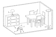
FIG. 1 is a system comprised of a vehicle and two illuminating devices;
FIG. 2 is the vehicle according to FIG. 1;
FIG. 3 is the system according to FIG. 1 during an operation;
FIG. 4 is a system comprised of a vehicle, two illuminating devices and an external controller during an operation.
DETAILED DESCRIPTION OF THE PREFERRED EMBODIMENTS
FIG. 1 shows a room in a home, in which a vehicle 1, here specifically an autonomous cleaning robot, is traveling. A plurality of objects 4 are arranged in the room, here specifically items of furniture, such as a table, several chairs and a chest of drawers. Also located in the room are two illuminating devices 5, specifically one standing lamp designed as a ceiling spot, and a table lamp located on the chest of drawers.
The vehicle 1 has electric motor-driven wheels 10 for automatically moving the vehicle 1, as well as a cleaning element 9, which is here designed as a rotating cylinder, for example. The vehicle 1 can basically be any kind of autonomous vehicle. Mentioned here only as examples are vacuuming robots, wiping robots, polishing robots, grinding robots or the like. The vehicle 1 has an integrated controller 7, which can generate control commands for the vehicle 1, in particular travel commands for navigating the vehicle 1 through the room while avoiding collisions with the objects 4. For example, the controller 7 is here a processor of the vehicle 1, which also serves to generate an area map 3 for the vehicle, and is linked with a data memory for storing the area map 3. The vehicle 1 further has a detection system 2 for detecting objects 4 within the environment of the vehicle 1. For example, the detection system 2 here has an image acquisition device, specifically a camera. The latter can be rotated by 360 degrees or have a lens that enables a panoramic view around the vehicle 1, for example a fisheye lens. In addition, the vehicle 1 has a communication system (not shown), here a WLAN module, which the vehicle 1 can use to communicate with other WLAN modules. Alternatively, other communication modules can also be used, of course, for example Bluetooth modules or others.
The vehicle 1 has a navigation system, which the vehicle 1 can use to orient itself within the environment. The navigation system here consists of the detection system 2 and, for example, an odometer system allocated to the wheels 10 of the vehicle 1, which records a distance traveled by the vehicle 1. The area map 3 can be generated from the data of the detection system 2 and odometer system. In the usual manner, the area map 3 contains the detected objects 4 and illuminating devices 5, which are also objects 4. Apart from the spatial position of an illuminating device 5, the area map 3 can also have additional information about the illuminating device 5, specifically an indication as to the type of illuminating device 5 and/or its light intensity and/or its emission spectrum and/or a position and/or size of a partial area of the environment 6 that can be illuminated by the illuminating device 5 and/or information about the type of illuminating device 5. For example, this information can be manually entered by a user via an input interface (not shown) and/or transferred from the respective illuminating device 5 to the vehicle 1 via a communication module. Alternatively, however, it is also possible that the vehicle 1 itself detect corresponding information during a learning run. To this end, for example, the vehicle 1 can have an intensity sensor and/or spectral sensor, which measures a light intensity of an illuminating device 5, potentially its emission spectrum and/or a position and/or size of a partial area of the environment 6 illuminated by the illuminating device 5. The illuminating devices 5 are advantageously turned on during the learning run, so that the vehicle 1 can perform the corresponding measurements. If the illuminating device 5 is a dimmable illuminating device 5 in terms of light intensity or an illuminating device 5 with a variable emission spectrum, it is recommended that the emission characteristics of the illuminating device 5 be varied while the vehicle 1 performs a corresponding measurement. In this way, comprehensive information about each individual illuminating device 5 can be detected and stored.
FIG. 2 shows a magnified view of the vehicle 1. An area map 3 is stored in a data memory of the controller 7. Among other things, this area map 3 contains a floor plan of the room depicted on FIG. 1. The area map 3 contains the positions of the detected objects 4 along with the positions of the detected illuminating devices 5. Also shown in relation to the two illuminating devices 5 are a respective position and size of a partial area of the environment 6 illuminated by the illuminating device 5. The partial area of the environment 6 is sketched in with a respective dashed perimeter. The sketched line here does not indicate an actual demarcation of the illuminated partial area of the environment 6, but rather a mathematical boundary within which the light intensity here measures roughly 70 percent of the maximum light intensity, for example. Since the illuminating devices 5 shown here are ones with a conical emission characteristic, the projections of the partial areas of the environment 6 onto the floor surface of the room are essentially circular. In relation to the illuminating device 5 designed as a ceiling spot, the partial area of the environment 6 sketched in the area map 3 is a partial area of the environment 6 of the floor surface being hit by the radiation reflected back from the illuminated ceiling.
FIG. 3 shows a situation in which the vehicle 1 travels within the room in order to perform a cleaning task there. For purposes of collision-free movement, the vehicle 1 orients itself to the area map 3. The detection system 2 here continuously records images of the environment, so as to continue the area map 3 and localize the current position of the vehicle 1 within the environment. There now exist areas within the room that are not illuminated by daylight enough to ensure an optimal quality of the recorded images, for example. As a result, it may not be possible to reliably detect or localize the outlines of objects 4, accumulations of coarse dirt or the like. Therefore, it is necessary to additionally illuminate the immediate surroundings of the vehicle 1 with one or several of the illuminating devices. In the example shown, the vehicle 1 is located next to the object 4 designed as a chest of drawers. For example, if a window in the room is located on the side of the object 4 opposite the vehicle 1, a shadow arises behind the object 4 that reduces the quality of the image recorded by the detection system 2 of the vehicle 1. The detection system 2 recognizes that the recorded images are not optimally illuminated, and transmits information about this to the controller 7 of the vehicle 1. The controller 7 thereupon checks the area map 3 to determine which illuminating devices 5 are available in the area of the room currently being traversed. The controller 7 here recognizes that the detection range of the detection system 2 extends into a partial area of the environment 6 that can be illuminated by the illuminating device 5 designed as a table lamp. The controller 7 then generates a control command for turning on the illuminating device 5. For example, the control command is here transmitted via a WLAN communication module. The detection system 2 can now record high-quality images within the partial area of the environment 6. Once the vehicle 1 has again left this partial area of the environment 6, the controller 7 of the vehicle 1 transmits a control command for turning off the illuminating device 5 to the illuminating device 5. If the vehicle 1 once again makes its way into an area of a room that is insufficiently illuminated as it continues traveling through the room or home, another check can be performed based on the area map 3 to determine which illuminating device 5 is suitable for illuminating a specific partial area of the environment 6. It can basically also be provided that an illuminating device 5 present in the travel path of the vehicle 1 always be turned on. As explained previously, however, it is alternatively also possible that the illuminating device 5 only be turned on when needed. It can further be provided that an illuminating device 5 be turned off as the vehicle 1 approaches the corresponding partial area of the environment 6. This can be advantageous if the detection system 2 of the vehicle 1 itself emits light, for example to measure a back reflection. In this case, it would be disadvantageous to additionally illuminate the environment with an illuminating device 5. In addition, it is also conceivable that the controller 7 of the vehicle 1 control the illuminating device 5 in relation to other parameters, for example in relation to its dimmable light intensity, a variable emission spectrum and/or a position and/or size of an illuminated partial area of the environment 6.
FIG. 4 shows a system consisting of a vehicle 1 automatically moving within the room, two illuminating devices 5 and a central controller 8. The system is here part of a home automation system, wherein communication between the vehicle 1 and illuminating devices 5 takes place via the central controller 8. The central controller 8 can be an access point of a WLAN home network. For example, in this embodiment of the invention, the vehicle 1 again travels within the room depicted and records images by means of the detection system 2. If the vehicle 1 gets into a partial area of the room only inadequately illuminated for optimally operating the detection system 2, the vehicle 1 sends a corresponding message to the central controller 8. The central controller 8 access an advantageously centrally stored area map 3 and checks which illuminating device 5 is located near the travel path of the vehicle 1. In particular, a check is performed to see whether a partial area of the environment 6 that can be illuminated by an illuminating device 5 extends into the travel path. In the example shown, both illuminating devices 5 are suitable for at least partially illuminating the current position of the vehicle 1. For this reason, the central controller 8 transmits a control command to each of the illuminating devices 5, whereupon the latter are turned on.
Embodiments in which an illuminating device 5 has a lamp with an emission spectrum in the infrared spectral range would also be possible, for example. The controller 7, 8 could specifically actuate this illuminating device 5, so that objects 4 can be better recognized, for example based on an optimized color differentiation. Infrared illumination could further also be advantageous in otherwise dark environments, for example so as not to disturb any people present. A recording rate for the detection system 2 can advantageously be selected in such a way as to exceed a variation rate of an emission spectrum of the illuminating device 5. In particular, it can be provided that the detection device 2 be synchronized with the illuminating device 5 in this regard. This can also help improve the recognition of objects 4.
In relation to all mentioned examples, it is of course also possible that the vehicle 1 itself have an integrated illuminating device 5, so as to support illumination at locations in the room where illumination by the external illuminating devices 5 is inadequate. For example, to this end, the vehicle 1 could have an illuminating device 5 that emits in an infrared spectral range or a visible spectral range.
REFERENCE LIST
1 Vehicle
2 Detection system
3 Area map
4 Objects
5 Illuminating device
6 Partial area of the environment
7 Controller
8 Controller
9 Cleaning element
10 Wheel

Claims (9)

What is claimed is:
1. An unmanned vehicle that moves automatically within an environment comprising:
a detection system configured for detecting object data in an environment of the vehicle;
a calculating device for generating an area map based on the detected object data, and
a controller, which is configured to generate a control command depending on an operation of the detection system and/or a lighting status in a detection range of the detection system
wherein the area map has positions of objects located within the environment, wherein the area map has information about a position of an external illuminating device designed separately from the vehicle, as well as one or several items of information about the illuminating device,
wherein the information is selected from the group consisting of: light intensity, emission spectrum, position of a partial area of an environment that can be illuminated by the illuminating device, and size of a partial area of an environment that can be illuminated by the illuminating device,
wherein the controller is configured to generate a control command that turns on the illuminating device if a partial area of the environment that can be illuminated by this illuminating device at least partially overlaps a detection range of the detection system.
2. The vehicle according to claim 1, wherein the vehicle has a communication module for communicating with an external illuminating device and/or a central controller of a home automation network.
3. A system comprised of at least one unmanned vehicle that moves automatically within an environment, comprising:
a detection system for detecting object data in an environment of the vehicle;
a calculating device for generating an area map based on recorded object data,
at least one external illuminating device designed separately from the vehicle, and
a controller configured for transmitting a control command to the illuminating device to turn on the lighting device,
wherein the area map has positions of objects located within the environment,
wherein the area map has information about the position of the illuminating device as well as one or more items of information about the illuminating device, and
wherein the information is selected from the group consisting of: light intensity, emission spectrum, position of a partial area of an environment that can be illuminated by the illuminating device, and size of a partial area of an environment that can be illuminated by the illuminating device.
4. The system according to claim 3, wherein the controller, is disposed remote from the vehicle and has a communications link to the vehicle and a communications link to the illuminating device.
5. The system according to claim 3, wherein the controller is set up to generate a control command for controlling the external lighting device and transmit the control command to the illuminating device and/or receive the control command from the vehicle and transmit it to the illuminating device.
6. The system according to claim 3, wherein the controller is configured to control the illuminating device when a partial area of an environment that can be illuminated by the illuminating device at least partially overlaps a detection range of the detection system of the vehicle, to turn on the illuminating device depending on a detected lighting status within the detection range.
7. The system according to claim 3, wherein the controller is set up to register vehicles and/or illuminating devices to the system and receive information about a position, a light intensity, an emission spectrum, a position and/or size of a partial area of the environment that can be illuminated by the illuminating device and/or a type of illuminating device.
8. A method for operating an unmanned vehicle that moves automatically within an environment, comprising:
detecting with a detection system of the vehicle an illuminating device within the environment,
recording with the detection system of the vehicle information about a position of the illuminating device as well as at least one additional item of information about the illuminating device, and
generating with a calculating device of the vehicle an area map based on recorded object data, and
turning on an illuminating device when a partial area of the environment that can be illuminated by this illuminating device at least partially overlaps a detection range of the detection system of the vehicle, such that the illuminating device is turned on depending on a detected lighting status within the detection range,
wherein the information is selected from the group consisting of: light intensity, emission spectrum, position of a partial area of an environment that can be illuminated by the illuminating device, and size of a partial area of an environment that can be illuminated by the illuminating device.
9. The method according to claim 8, further comprising the step of generating a control command with a controller of the vehicle for controlling an external illuminating device and transmitting the control command to the illuminating device, or generating a control command with a controller of the system that is disposed remote from the vehicle and transmitting the control command to the illuminating device, or receiving a control command from the vehicle and transmitting the control command to the illuminating device.
US16/002,251 2017-06-09 2018-06-07 Vehicle that moves automatically within an environment as well as a system with a vehicle and an external illuminating device Active US10444765B2 (en)

Applications Claiming Priority (3)

Application Number Priority Date Filing Date Title
DE102017112793 2017-06-09
DE102017112793.3A DE102017112793A1 (en) 2017-06-09 2017-06-09 Self-propelled vehicle within an environment as well as system with a vehicle and an external illumination device
DE102017112793.3 2017-06-09

Publications (2)

Publication Number Publication Date
US20180356834A1 US20180356834A1 (en) 2018-12-13
US10444765B2 true US10444765B2 (en) 2019-10-15

Family

ID=62196349

Family Applications (1)

Application Number Title Priority Date Filing Date
US16/002,251 Active US10444765B2 (en) 2017-06-09 2018-06-07 Vehicle that moves automatically within an environment as well as a system with a vehicle and an external illuminating device

Country Status (7)

Country Link
US (1) US10444765B2 (en)
EP (1) EP3412192B1 (en)
JP (1) JP2019003626A (en)
CN (1) CN109032126B (en)
DE (1) DE102017112793A1 (en)
ES (1) ES2916253T3 (en)
TW (1) TW201904507A (en)

Families Citing this family (7)

* Cited by examiner, † Cited by third party
Publication number Priority date Publication date Assignee Title
DE102017112796A1 (en) * 2017-06-09 2018-12-13 Vorwerk & Co. Interholding Gmbh Self-propelled soil tillage implement
DE102019201692A1 (en) * 2019-02-11 2020-08-13 Zf Friedrichshafen Ag Method and system for limiting and monitoring at least one work area for at least one autonomously operated vehicle
CN110412988A (en) * 2019-08-21 2019-11-05 上海敖颉信息科技有限公司 A method for navigating port container unmanned vehicles by using port lights
US11480431B1 (en) * 2019-08-27 2022-10-25 Alarm.Com Incorporated Lighting adaptive navigation
CN112641382B (en) * 2019-10-12 2022-05-06 尚科宁家(中国)科技有限公司 Light supplement control method for sweeping robot and sweeping robot
DE102019131583A1 (en) * 2019-11-22 2021-05-27 Vorwerk & Co. Interholding Gmbh System with at least two automatically moving soil cultivation devices as well as a method for operating a system
DE102021127083A1 (en) 2021-10-19 2023-04-20 Bayerische Motoren Werke Aktiengesellschaft Lamp control device for controlling an operating state of a lamp and lamp control method

Citations (9)

* Cited by examiner, † Cited by third party
Publication number Priority date Publication date Assignee Title
US20060237634A1 (en) * 2005-04-23 2006-10-26 Lg Electronics Inc. Position sensing device for mobile robots and robot cleaner equipped with the same
US20100152944A1 (en) * 2008-12-11 2010-06-17 Kabushiki Kaisha Yaskawa Denki Robot system
US20130009569A1 (en) * 2010-03-25 2013-01-10 Koninklijke Philips Electronics, N.V. Method of controlling an outdoor lighting system, a computer program product, a controlling device and an outdoor lighting system
US20130056032A1 (en) * 2011-09-07 2013-03-07 Suuk Choe Robot cleaner, and system and method for remotely controlling the same
US9179526B2 (en) * 2012-06-12 2015-11-03 Hesa Light A/S Lighting system with illuminance control
US9274525B1 (en) * 2012-09-28 2016-03-01 Google Inc. Detecting sensor degradation by actively controlling an autonomous vehicle
US20160147230A1 (en) * 2014-11-26 2016-05-26 Irobot Corporation Systems and Methods for Performing Simultaneous Localization and Mapping using Machine Vision Systems
US20160144505A1 (en) * 2014-11-26 2016-05-26 Irobot Corporation Systems and Methods for Performing Occlusion Detection
US20180125003A1 (en) * 2014-09-23 2018-05-10 Positec Technology (China) Co., Ltd. Self-moving robot

Family Cites Families (10)

* Cited by examiner, † Cited by third party
Publication number Priority date Publication date Assignee Title
RU2220643C2 (en) * 2001-04-18 2004-01-10 Самсунг Гванджу Электроникс Ко., Лтд. Automatic cleaning apparatus, automatic cleaning system and method for controlling of system (versions)
KR101337534B1 (en) * 2007-07-24 2013-12-06 삼성전자주식회사 Apparatus and method for localization of moving robot
DE102009052629A1 (en) * 2009-11-10 2011-05-12 Vorwerk & Co. Interholding Gmbh Method for controlling a robot
US8515289B2 (en) * 2011-11-21 2013-08-20 Environmental Light Technologies Corp. Wavelength sensing lighting system and associated methods for national security application
DE102012014939A1 (en) * 2012-07-27 2014-01-30 Volkswagen Aktiengesellschaft Method and device for collision avoidance
US9380922B2 (en) * 2013-01-18 2016-07-05 Irobot Corporation Environmental management systems including mobile robots and methods using same
EP3127403B8 (en) * 2014-04-04 2019-04-10 Signify Holding B.V. System and methods to support autonomous vehicles via environmental perception and sensor calibration and verification
DE102014008687A1 (en) * 2014-06-12 2015-12-17 GM Global Technology Operations LLC (n. d. Ges. d. Staates Delaware) Method for displaying vehicle surroundings information of a motor vehicle
CN104317199A (en) * 2014-09-16 2015-01-28 江苏大学 Mobile smart housekeeper
KR101659037B1 (en) * 2015-02-16 2016-09-23 엘지전자 주식회사 Robot cleaner, remote controlling system and method of the same

Patent Citations (9)

* Cited by examiner, † Cited by third party
Publication number Priority date Publication date Assignee Title
US20060237634A1 (en) * 2005-04-23 2006-10-26 Lg Electronics Inc. Position sensing device for mobile robots and robot cleaner equipped with the same
US20100152944A1 (en) * 2008-12-11 2010-06-17 Kabushiki Kaisha Yaskawa Denki Robot system
US20130009569A1 (en) * 2010-03-25 2013-01-10 Koninklijke Philips Electronics, N.V. Method of controlling an outdoor lighting system, a computer program product, a controlling device and an outdoor lighting system
US20130056032A1 (en) * 2011-09-07 2013-03-07 Suuk Choe Robot cleaner, and system and method for remotely controlling the same
US9179526B2 (en) * 2012-06-12 2015-11-03 Hesa Light A/S Lighting system with illuminance control
US9274525B1 (en) * 2012-09-28 2016-03-01 Google Inc. Detecting sensor degradation by actively controlling an autonomous vehicle
US20180125003A1 (en) * 2014-09-23 2018-05-10 Positec Technology (China) Co., Ltd. Self-moving robot
US20160147230A1 (en) * 2014-11-26 2016-05-26 Irobot Corporation Systems and Methods for Performing Simultaneous Localization and Mapping using Machine Vision Systems
US20160144505A1 (en) * 2014-11-26 2016-05-26 Irobot Corporation Systems and Methods for Performing Occlusion Detection

Also Published As

Publication number Publication date
DE102017112793A1 (en) 2018-12-13
ES2916253T3 (en) 2022-06-29
US20180356834A1 (en) 2018-12-13
TW201904507A (en) 2019-02-01
CN109032126B (en) 2023-05-23
EP3412192B1 (en) 2022-04-27
EP3412192A1 (en) 2018-12-12
CN109032126A (en) 2018-12-18
JP2019003626A (en) 2019-01-10

Similar Documents

Publication Publication Date Title
US10444765B2 (en) Vehicle that moves automatically within an environment as well as a system with a vehicle and an external illuminating device
CN103947295B (en) For the configuration of the drive unit of luminescent device
EP3691417B1 (en) Automatic stage lighting tracking system and control method therefor
US9035555B2 (en) Medical lighting device and process for operating a medical lighting device
US12192027B2 (en) Camera-based commissioning and control of devices in a load control system
US9723693B1 (en) Lighting devices configurable for generating a visual signature
EP2116107A1 (en) Controllable lighting system, pointing device therefore and method of lighting control
CN105830538B (en) Lighting system and method of operating a lighting system
WO2009004539A1 (en) Light control system with automatic position detection of objects and method for controlling a lighting system by automatically detecting the position of objects
US20170265279A1 (en) Controlling lighting dynamics
CN107430181A (en) The method of tracing system and the carrier for following the trail of mobile comm unit
US20090265133A1 (en) Localization system and method for mobile object using wireless communication
JP2009053118A (en) Direction identification system
JP2009238529A (en) Illumination control system
EP2923533A2 (en) Configuration of operating devices for illuminants
KR100776804B1 (en) Location recognition device and method capable of interworking sensor network communication
GB2563737A (en) Automated luminaire identification and group assignment devices, systems and methods using dimming function
EP2680674B1 (en) Lighting System
CN112484713A (en) Map construction method, navigation method and control system of mobile robot
CN110566839A (en) indoor positioning energy-saving lighting device and navigation system thereof
JP3218472U (en) Indoor positioning energy saving lighting device and guidance system including the same
JP2019102307A (en) Lighting system
CN118358411A (en) Autonomous localization using optical filtering via transient synchronized illumination and sensing
DE102017110359A1 (en) AUTOMATED PICKING LIGHTS
JP2020095321A (en) Information system and information transmission method

Legal Events

Date Code Title Description
FEPP Fee payment procedure

Free format text: ENTITY STATUS SET TO UNDISCOUNTED (ORIGINAL EVENT CODE: BIG.); ENTITY STATUS OF PATENT OWNER: LARGE ENTITY

STPP Information on status: patent application and granting procedure in general

Free format text: DOCKETED NEW CASE - READY FOR EXAMINATION

AS Assignment

Owner name: VORWERK & CO. INTERHOLDING GMBH, GERMANY

Free format text: ASSIGNMENT OF ASSIGNORS INTEREST;ASSIGNORS:ERKEK, DAVID;HACKERT, GEORG;ISENBERG, GERHARD;AND OTHERS;SIGNING DATES FROM 20180709 TO 20180719;REEL/FRAME:046523/0192

STPP Information on status: patent application and granting procedure in general

Free format text: NON FINAL ACTION MAILED

STPP Information on status: patent application and granting procedure in general

Free format text: NOTICE OF ALLOWANCE MAILED -- APPLICATION RECEIVED IN OFFICE OF PUBLICATIONS

STPP Information on status: patent application and granting procedure in general

Free format text: PUBLICATIONS -- ISSUE FEE PAYMENT RECEIVED

STCF Information on status: patent grant

Free format text: PATENTED CASE

MAFP Maintenance fee payment

Free format text: PAYMENT OF MAINTENANCE FEE, 4TH YEAR, LARGE ENTITY (ORIGINAL EVENT CODE: M1551); ENTITY STATUS OF PATENT OWNER: LARGE ENTITY

Year of fee payment: 4