US10442394B2 - Belt tongue comprising a torsion bar - Google Patents

Belt tongue comprising a torsion bar Download PDF

Info

Publication number
US10442394B2
US10442394B2 US15/513,587 US201515513587A US10442394B2 US 10442394 B2 US10442394 B2 US 10442394B2 US 201515513587 A US201515513587 A US 201515513587A US 10442394 B2 US10442394 B2 US 10442394B2
Authority
US
United States
Prior art keywords
clamping element
torsion bar
tongue body
tongue
belt
Prior art date
Legal status (The legal status is an assumption and is not a legal conclusion. Google has not performed a legal analysis and makes no representation as to the accuracy of the status listed.)
Active
Application number
US15/513,587
Other versions
US20170297528A1 (en
Inventor
Michel Hermann
Martin Grikschat
Inga Krambeck
Hans-Jörg Cord
Current Assignee (The listed assignees may be inaccurate. Google has not performed a legal analysis and makes no representation or warranty as to the accuracy of the list.)
Autoliv Development AB
Original Assignee
Autoliv Development AB
Priority date (The priority date is an assumption and is not a legal conclusion. Google has not performed a legal analysis and makes no representation as to the accuracy of the date listed.)
Filing date
Publication date
Application filed by Autoliv Development AB filed Critical Autoliv Development AB
Assigned to AUTOLIV DEVELOPMENT AB reassignment AUTOLIV DEVELOPMENT AB ASSIGNMENT OF ASSIGNORS INTEREST (SEE DOCUMENT FOR DETAILS). Assignors: GRIKSCHAT, MARTIN, CORD, Hans-Jörg, HERMANN, MICHEL, KRAMBECK, INGA
Publication of US20170297528A1 publication Critical patent/US20170297528A1/en
Application granted granted Critical
Publication of US10442394B2 publication Critical patent/US10442394B2/en
Active legal-status Critical Current
Anticipated expiration legal-status Critical

Links

Images

Classifications

    • BPERFORMING OPERATIONS; TRANSPORTING
    • B60VEHICLES IN GENERAL
    • B60RVEHICLES, VEHICLE FITTINGS, OR VEHICLE PARTS, NOT OTHERWISE PROVIDED FOR
    • B60R22/00Safety belts or body harnesses in vehicles
    • B60R22/18Anchoring devices
    • B60R22/185Anchoring devices with stopping means for acting directly upon the belt in an emergency, e.g. by clamping or friction
    • B60R22/1855Anchoring devices with stopping means for acting directly upon the belt in an emergency, e.g. by clamping or friction the means being sensitive to belt tension
    • AHUMAN NECESSITIES
    • A44HABERDASHERY; JEWELLERY
    • A44BBUTTONS, PINS, BUCKLES, SLIDE FASTENERS, OR THE LIKE
    • A44B11/00Buckles; Similar fasteners for interconnecting straps or the like, e.g. for safety belts
    • A44B11/25Buckles; Similar fasteners for interconnecting straps or the like, e.g. for safety belts with two or more separable parts
    • A44B11/2503Safety buckles
    • A44B11/2546Details
    • A44B11/2553Attachment of buckle to strap
    • A44B11/2557Attachment of buckle to strap with strap length adjustment
    • AHUMAN NECESSITIES
    • A44HABERDASHERY; JEWELLERY
    • A44BBUTTONS, PINS, BUCKLES, SLIDE FASTENERS, OR THE LIKE
    • A44B11/00Buckles; Similar fasteners for interconnecting straps or the like, e.g. for safety belts
    • A44B11/25Buckles; Similar fasteners for interconnecting straps or the like, e.g. for safety belts with two or more separable parts
    • A44B11/2503Safety buckles
    • A44B11/2546Details
    • A44B11/2561Tongue elements
    • BPERFORMING OPERATIONS; TRANSPORTING
    • B60VEHICLES IN GENERAL
    • B60RVEHICLES, VEHICLE FITTINGS, OR VEHICLE PARTS, NOT OTHERWISE PROVIDED FOR
    • B60R22/00Safety belts or body harnesses in vehicles
    • B60R22/18Anchoring devices
    • B60R2022/1812Connections between seat belt and buckle tongue

Definitions

  • the present invention relates to a belt tongue for a motor vehicle seat belt restraint system including a tongue body extending in an insertion direction, wherein a clamping element is disposed such that a belt strap guided through a cavity in the tongue body and extending through a gap formed between the clamping element and the tongue body is movable by the tongue body in an unstressed, pass-through position, and in a stressed position caused by a tensile force introduced into the belt strap, is clamped to a clamp edge of the cavity by means of the clamp element pivot-mounted in the tongue body and pivoting into the cavity, wherein in the stressed position, a pre-stress device exerts a restoring force on the clamping element directed toward the pass-through position of the clamping element.
  • a belt tongue having the above-mentioned features is known, for example, from DE 20 2010 013 986 U1.
  • a clamping device referred to as a locking cam is pivotably supported in the tongue body, wherein a spring is provided as a pre-stress device that applies a force to the clamping element pivotably supported in the tongue body in a pass-through position.
  • a spring is provided as a pre-stress device that applies a force to the clamping element pivotably supported in the tongue body in a pass-through position.
  • the belt strap extending through a cavity in the tongue body is clamped between the clamping element and a clamping edge formed on the cavity, extending parallel to the surface of the belt strap.
  • the belt strap is also clamped at the lateral regions of the clamping element between the clamping element and a lateral edge of the cavity, wherein the belt strap is kinked.
  • the disadvantage results therefrom that in a stressed position, the force applied by the spring is not sufficient to release the locking position caused by the later
  • the object of the present invention is therefore to at least partially solve the problems outlined with respect to the prior art and in particular to specify a belt tongue wherein the locking position of the belt strap between the clamping element and a lateral edge of the cavity can be released.
  • a belt tongue including the above-mentioned features, wherein the pre-stress device is a torsion bar attached in the tongue body for conjoint rotation therewith and connected to the clamping element for conjoint rotation therewith.
  • the clamping element is pivotably supported by the torsion bar.
  • the clamping element is not pivotably supported by the torsion bar.
  • the tongue body thus includes a cavity through which the belt strap is guided.
  • the tongue body comprises in particular a metallic core and a plastic part molded onto the core.
  • the tongue body further includes a clamping element, which is pivotably supported on the tongue body, wherein the clamping element includes in particular a clamping region that comes into abutment with the belt strap at least in the stressed position.
  • the gap formed in particular between the clamping region of the clamping element and a clamping edge of the cavity, which clamping edge extends in particular parallel to the clamping region and the belt surface is sufficiently large that the belt strap is freely movable through the gap.
  • a tensile force is now applied to a belt tongue inserted into a belt buckle, then a force is applied by the belt strap onto the clamping element such that the clamping element pivots and consequently the gap between the clamp region of the clamping element and the clamping edge of the cavity is diminished, wherein in particular the clamping region of the clamping element is pivoted into the cavity. If the force introduced into the lap belt is great enough, then the belt strap is fixedly clamped in the cavity between the clamping region of the clamping element and the clamping edge of the cavity.
  • the torsion bar exerts a restoring force on the clamping element.
  • the torsion bar is elastically deformed, in particular twisted, from the pass-through position into the stressed position, wherein the clamping element is pivoted in particular by at most 60, preferably by at most 40.
  • the torsion bar is made of a suitable material. With the twisting of the torsion bar about its longitudinal axis, which twisting is generated by the pivoting of the clamping element and occurs at least in partial sections, wherein a torsional moment acts on the torsion bar, the torsion bar thus exerts a torque directed opposite the torsional moment, which results in the restoring force on the clamping element.
  • the torsion bar can be designed as a single piece with the clamping element, or can be an individual part of the belt tongue. The torsion bar can generate a relatively large restoring force.
  • the torsion bar can also have an additional function.
  • the clamping element is pivotably supported in the tongue body by the torsion bar. Then in particular no further provisions are made for a pivot support of the torsion bar in the tongue body.
  • the torsion bar is only attached to one side of the tongue body for conjoint rotation therewith (i.e. fixed regarding relative rotation), and is only connected to the clamping element on the side of the clamping element that is not associated with the side of the tongue body attached to the torsion bar. Due to the attachment of the torsion bar to the tongue body and the clamping element, as provided on different sides of the belt tongue, the region of the torsion bar twisted in the event of a pivoting of the clamping element has a maximum length, whereby an elastic (rotational) deforming of the torsion bar occurs across the possible angular range.
  • the invention provides that guide sections are disposed laterally on the clamping element, between which the belt strap extends so that in the lateral region of the cavity the belt strap does not arrive between the clamping element and the tongue body.
  • the cavity has recesses formed to the side of the clamping edge, aligned in the insertion direction, in which the guide sections of the clamping element are disposed at least in the stressed position. Guide sections in particular protruding over the clamping region of the clamping element are thus disposed laterally on the clamping element.
  • the guide sections extend in particular in a direction out over the clamping region of the clamping element, on which region the belt strap is guided by the tongue body both in the pass-through position and in the stressed position. Consequently the belt is laterally delimited by the guide sections and can in particular not come into abutment with the lateral edges of the cavity.
  • the guide sections of the clamping element engage in the recesses or are in particular also already disposed in the recesses in the pass-through position, which recesses extend laterally from the clamp edge in the insertion direction and thus form a region of the opening. Due to the recesses extending in the insertion direction, the installation height of the belt tongue can be reduced in the insertion direction.
  • the guide sections each have in particular a circular-arc-shaped edge that is disposed in the recess at least in the stressed position, but does not protrude over the tongue body.
  • the projection is formed in particular on side of the cavity opposite the clamping edge of the cavity.
  • the projection forms a stop for the pivoting movement of the clamping element, whereby in the stressed position, as the force introduced into the belt strap increases, the force acting on the belt strap is limited, since after abutment of the end surfaces of the groove on the projection, the force is introduced into the tongue body and a further pivoting of the clamping element no longer occurs. Consequently, a self-clamping of the belt strap could be avoided in the attachment position, and in a design without guide sections on the clamping element, the locking force of a portion of the belt strap arriving between the clamping element and the lateral edge of the opening could be limited. Consequently, despite the clamping of the belt strap between clamping element and lateral edge of the opening, a reversing from the locking position into the pass-through position is possible.
  • one guide element projects laterally from each of the two guide sections, which guide elements are disposed at least partially surrounding the sockets accommodating the torsion bar, or are disposed at the guide depressions in the tongue body abutting against the sockets.
  • the guide elements and the guide depressions are formed such that the pivot movement of the clamping element is guided by the guide elements moved into the guide depressions. Due to this design, an additional or alternative pivoting support can be formed, wherein the guide depressions preferably also form a stop for the pivot movement of the clamping element.
  • the clamping element is not pivotably supported by the torsion bar, it is preferred that no guide element respectively projects laterally from the two guide sections and that none of the sockets receiving the torsion bar are disposed in the tongue body at least partially surrounding the guide depressions.
  • the clamping element is preferably pivotably supported on the buckle body predominantly via the guide elements engaging in the guide depressions, so that the torsion bar is present mainly for providing the restoring force and has no influence on the pivoting support.
  • the present invention provides that a rectilinear assembly depression extending up to an edge of the tongue body respectively, connects to the guide depressions, by which the clamping element is linearly displaced with the guide elements during assembly, wherein the clamping element is secured against shifting back due to subsequent pivoting.
  • a projection of the guide elements onto the respective assembly depressions is greater than the width of the corresponding assembly depressions, so that the guide elements cannot arrive back in the assembly depressions.
  • the torsion bar can be introduced through the clamping element, so that even after pivoting back, the clamping element is secured by the assembly depression against shifting back.
  • the torsion bar has two functions. On the one hand it secures the clamping element against shifting back, and on the other hand provides a restoring force with the pivoting of the clamping element. A simple assembly of the clamping element and the torsion bar is thus also possible.
  • the invention provides that the belt strap is simply pulled through the opening in the tongue body transverse to the insertion direction, by which it is meant that the belt strap is guided only once through the tongue body, namely through the cavity in the tongue body and thus extends through the tongue body from a front side of the belt tongue to a rear side of the belt tongue. It is thereby precluded in particular that the belt strap forms a loop in the region of the belt tongue, wherein the belt strap has been introduced into the belt tongue from the same side in which it has also been guided out.
  • the torsion bar already exerts a force in the pass-through position on the clamping element directed opposite the stressed position.
  • the advantage obtained is that the clamping element is always pre-stressed in a position such that rattling noises can be avoided.
  • the present invention provides in particular that a socket on the tongue body that is provided for conjoint rotation with the torsion bar, and the torsion bar itself are configured such that a first end of the torsion bar, which end is to be fixed in the socket, must be twisted for fixing on the tongue body opposite the second end placed on the clamping element for conjoint rotation therewith, while the clamping element is located in the pass-through position.
  • the clamping element is thus first engaged in the tongue body and oriented such that the torsion bar can be introduced by the second end through the socket in the tongue body in a channel in the torsion bar.
  • the torsion bar and the channel in the clamping element are at least regionally configured such that they cannot be rotated relative to each other.
  • the first end of the torsion bar When the torsion bar is inserted into this region by its second end, the first end of the torsion bar must be twisted forming a torsional moment in the torsion bar, until the first end can be introduced into the corresponding socket in the tongue body. Due to the torsional moment present in the torsion bar, a pre-stress is induced on the clamping element. In particular, after the opposite-side twisting of the first and second end, the torsion bar must still be axially pushed into the corresponding socket in the tongue body.
  • the invention provides that the torsion bar includes a first cross-sectional contour on the first end to be fixed in the socket, which contour corresponds to a second contour of the second end of the cross-sectional shape, which second end is placed in the clamping element for conjoint rotation therewith, wherein in a relaxed state of the torsion bar the cross-sectional contours of the two ends are rotated with respect to each other about an axis of rotation and the transition from the first cross-sectional contour to the second cross-sectional contour is continuous, while maintaining the cross-sectional shape, so that with the second end placed in the clamping element for conjoint rotation therewith, the torsion bar is twisted exclusively by insertion of the first end into the socket.
  • the invention provides that in a not-yet engaged state, the torsion bar has a twisted shape in its longitudinal extension, which twisted shape is necessarily untwisted during insertion of the torsion bar into the clamping element and into the socket in the tongue body, whereby a torsional moment is induced in the torsion bar, which applies a force onto the clamping element in the pass-through position.
  • FIGS. 1( a ) and 1( b ) are exploded views of a first embodiment of a belt tongue
  • FIG. 2 shows a rear side of the belt tongue
  • FIG. 3 shows a section of the belt tongue
  • FIG. 4 shows a front side of the belt tongue
  • FIG. 5 is a sectional depiction through the belt tongue in a pass-through position
  • FIG. 6 is a sectional view of the belt tongue in a stressed position
  • FIG. 7 is a front view of a second embodiment of a belt tongue
  • FIG. 8 shows a torsion bar of the second embodiment of the belt tongue
  • FIGS. 9-11 are detailed views of the second embodiment of the belt tongue
  • FIG. 12 is an exploded view of a third embodiment of the belt tongue
  • FIG. 13 is a sectional view through the third embodiment of the belt tongue
  • FIG. 14 is a further sectional view through the third embodiment of the belt tongue
  • FIG. 15 shows a torsion bar of a fourth embodiment of the belt tongue
  • FIG. 16 illustrates a fourth embodiment of the belt tongue
  • FIGS. 17( a ), 17( b ), and 17( c ) show an assembly sequence of the fourth belt tongue
  • FIG. 18 is a detailed view of a fifth embodiment of the belt tongue.
  • the first exemplary embodiment of a belt tongue 1 depicted in FIGS. 1 to 4 serves for explaining the functionality of the belt tongue 1 , but does not have all claimed features.
  • the belt tongue 1 comprises a tongue body 3 that extends in an insertion direction 2 .
  • a cavity 5 is formed in the tongue body 3 , which is bounded below in sections, in the insertion direction 2 by a clamping edge 8 .
  • recesses 10 extend in the insertion direction 2 .
  • projections 14 on the tongue body 3 are formed and protrude into the cavity 5 .
  • a retaining point 17 is formed and a middle region of a leaf spring 12 comes to rest thereon.
  • the belt tongue 1 further includes a clamping element 4 that is pivotably supported in the tongue body 3 by bearing pins 18 .
  • a cam 11 tapering in one direction is formed adjacent to each bearing pin 18 . In the assembled state the ends of the leaf spring 12 rest on the cam 11 such that a torque is introduced into the clamping element 4 .
  • the clamping element 4 further includes grooves 15 with end surfaces 16 in which the projections 14 are disposed in the assembled state of the belt tongue 1 .
  • the clamping element 4 further includes guide sections 9 in the lateral region which in the assembled state are at least partially disposed in the recess 10 of the cavity 5 .
  • a gap is formed between a clamping region 22 of the clamping element 4 and the clamping edge 8 of the cavity 5 , through which a belt strap 7 is guidable.
  • This gap 6 is delimited on both sides by the guide sections 9 of the clamping element 4 , so that the belt strap 7 is disposed between the guide sections 9 .
  • the belt strap 7 thus cannot arrive between the clamping element 4 and a lateral edge 19 of the cavity 5 .
  • the gap 6 formed between the clamping region 22 of the clamping element 4 and the clamping edge 8 of the cavity 5 is sufficiently large that the belt strap 7 is freely movable.
  • the belt strap 7 here is laterally delimited by the guide sections 9 .
  • FIG. 7 a second embodiment of a belt tongue having all features essential to the invention is depicted, which differs from the first embodiment primarily through the provision of a pivotable support of the clamping element 4 and the applying of a restoring force, wherein in addition the function of the clamping element 4 and the guide section 9 attached thereto is identical to the first embodiment, so that hereinafter only the differences are discussed.
  • the clamping element 4 is pivotably supported by an elastically deformable torsion bar 13 on the tongue body 3 , wherein in the stressed position, the torsion bar 13 simultaneously exerts a restoring force on the clamping element 4 .
  • the torsion bar 13 is attached on a first side 20 of the tongue body 3 for conjoint rotation therewith, i.e. they are fixed for non-rotatable relative motion), by means of a friction fit into a first socket 28 a on the tongue body 3 .
  • Such connection is provided by the profiled head 35 of the torsion bar 13 which form fits into socket 28 a .
  • the torsion bar 13 which is guided through the entire clamping element 4 is rotatably supported in a socket 28 b in the tongue body 3 , as can be seen from FIG. 11 .
  • the end of the torsion bar 13 is permitted to rotate within socket 28 b.
  • the torsion bar 13 depicted in FIG. 8 can be deformed (twisted) over a longest possible length during a twisting (rotational) movement of the clamping element 4 , the torsion bar 13 is only connected to the clamping element 4 for conjoint rotation therewith (i.e. rotatably fixed) on a side of the clamping element 4 associated with the second side 21 of the tongue body 3 by form fits provided by the mating cross-sectional configurations of the torsion bar 13 and an internal socket 36 at an end of the clamping element 4 , as is depicted in FIGS. 10 and 14 .
  • the clamping element 4 further has an internal passageway (not shown) for torsion bar 13 which allows the torsion bar to twist between the ends of the clamping element 4 .
  • the torsion bar 13 is disposed on the side of the clamping element 4 associated with the first side 20 of the tongue body 3 rotatable with respect to the clamping element 4 in the socket 28 .
  • the torsion bar 13 is twisted over almost its entire length between the attachment for conjoint rotation to the first side 20 of the clamping element 4 at socket 28 a and the connection for conjoint rotation of the torsion bar 13 to the clamping element 4 at socket 36 , wherein due to the resultant elastic deformation of the torsion bar 13 , a restoring force is exerted on the clamping element 4 .
  • FIG. 12 a third embodiment of a belt tongue 1 having all essential features of the invention is depicted, wherein the functional principle of the belt tongue 1 essentially corresponds to the functional principle of the previously described belt tongues. Similar to the second embodiment, the belt tongue 1 includes a torsion bar 13 , which exerts a restoring force on the clamping element 4 directed in the pass-through position during pivoting of the clamping element 4 . In the following therefore mainly the differences to the above-described embodiments are discussed.
  • the clamping element 4 features guide elements 23 laterally outward on its guide sections 9 .
  • the tongue body 3 features guide depressions 24 corresponding to the guide elements 23 , and an assembly depression 25 adjoins each of these guide depressions.
  • the guide cavity 24 is configured in approximately a half-ring shape, to which the rectilinear assembly depression 25 connects. Due to the assembly depressions 25 , the clamping element 4 can be brought into its assembly position with its quarter-ring-shaped guide elements 23 .
  • the clamping element 4 is linearly displaced on both sides with the guide elements 23 through the assembly depressions 25 , wherein the clamping element 4 is prevented from slipping back against the now greater extension of the guide elements 23 , as projected onto the width of the assembly depressions 25 . Due to the guide elements 23 and the guide depressions 24 , a pivoting support of the clamping element 4 in the tongue body 3 is thus achieved.
  • the torsion bar 13 disposed in the sockets 28 in the clamping element 4 not only has the function of exerting a restoring force on the pivoted clamping element 4 , but also the function of securing the clamping element 4 against slipping back through the assembly depressions 25 into a correspondingly pivoted position.
  • the tongue body 3 is formed of a metallic core 26 with molded-over plastic 27 .
  • FIG. 14 a sectional view is shown through the tongue body 3 in the region of the guide section 9 .
  • the guide section 9 is disposed in a recess 10 formed in the plastic 27 , wherein the clamping element slides into abutment on the plastic 27 in the upper region of the cavity 5 during the pivoting movement.
  • a torsion bar 13 is shown for a fourth embodiment of a belt tongue 1 having all features essential to the invention.
  • the torsion bar 13 includes a first end 29 and a second end 30 .
  • the second end 30 is secured from twisting with respect to a clamping element 4 , but it can be twisted with respect to a further socket in the tongue body 3 .
  • the torsion bar 13 has a first cross-sectional contour 31 and in the region of the second end 30 , a second cross-sectional contour 32 .
  • the cross-sectional contours 31 , 32 are identical in their shape, wherein, however, they are rotationally offset to each other with respect to a longitudinal axis of the torsion bar 13 .
  • the torsion bar 13 continuously transitions from the first end 29 to the second end 30 while maintaining the cross-sectional shape, wherein the orientation of the cross-sectional shape changes.
  • FIG. 16 the belt tongue 1 is depicted with installed clamping element 4 and installed torsion bar 13 .
  • the tongue body 3 of the belt tongue 1 includes sockets 28 on its lateral walls, whose socket cross-sections 33 are respectively depicted on the bottom of FIG. 16 .
  • the socket 28 includes a socket cross-section 33 that corresponds in shape to the cross-sectional shape of the torsion bar 13 .
  • the socket 28 has a circular socket cross-section, so that the torsion bar 13 can rotate in this socket 28 by its second end 30 .
  • the clamping element 4 includes a channel for receiving the torsion bar 13 whose channel cross section 34 is indicated in the bottom of FIG. 16 .
  • the cross-section of the channel has a circular shape
  • the cross-section of the channel has a rectangular shape corresponding to the cross-sectional shape of the torsion bar 13 .
  • the torsion bar 13 is initially introduced into the channel of the clamping element 4 through the socket 28 .
  • the clamping element here can initially be in any orientation since the torsion bar is rotatable relative to the clamping element on the left side depicted in the Figure, due to the circular channel cross-section 34 .
  • the clamping element 4 In order to push the torsion bar 4 farther into the clamping element 4 as shown in FIG. 17( b ) , the clamping element 4 should be located in its pass-through position so that the second end of the torsion bar 13 can engage in the cross-sectional contour of the channel adapted to the second end 30 .
  • the torsion bar 13 having a twisted shape must be twisted by its first end 29 with respect to the second end 30 fixed against a relative rotation in the clamping element 4 , whereby a torsional moment is generated in the torsion bar 30 , which position is shown in FIG. 17( c ) .
  • the restoring force resulting therefrom is directed in the pass-through position of the clamping element 4 .
  • the torsion bar 13 is angled in the region of its first end 29 .
  • the torsion bar 13 already fixed to the clamping element 4 for conjoint rotation therewith by its second end 30 must be twisted by the first end 29 relative to the second end 30 so that the angled end 29 can engage in the correspondingly formed socket 28 in the belt body 3 .
  • a pre-stress is generated in advance in the pass-through position.

Landscapes

  • Engineering & Computer Science (AREA)
  • Mechanical Engineering (AREA)
  • Clamps And Clips (AREA)
  • Automotive Seat Belt Assembly (AREA)

Abstract

A belt tongue (1) having a tongue body (3) extending in an insertion direction (2), a clamping element (4) in the tongue body such that a belt strap (7) guided through a cavity (5) in the tongue body (3) and running through a gap (6) can be moved through the tongue body (3) in an unstressed free-running position and, in a stressed position brought about by a tensile force in the belt strap (7), is clamped on a clamping edge (8) of the cavity (5) by the clamping element (4) that is pivotally mounted in the tongue body (3). A pre-tensioning device exerts a retractive force on the clamping element (4), at least in the stressed position, the force being oriented in the direction of the free-running position of the clamping element (4). The pre-tensioning device is a torsion bar (13) that is non-rotatably secured in the tongue body (3) and non-rotatably connected to the clamping element (4).

Description

CROSS-REFERENCE TO RELATED APPLICATIONS
This application is a 35 U.S.C. § 371 national phase application of International PCT Application No.: PCT/EP2015/072514, filed Sep. 30, 2015, which claims the benefit of priority to German Patent Application No.: 10 2014 114 207.1, filed Sep. 30, 2014, the contents of which are incorporated herein by reference in their entirety.
FIELD OF THE INVENTION
The present invention relates to a belt tongue for a motor vehicle seat belt restraint system including a tongue body extending in an insertion direction, wherein a clamping element is disposed such that a belt strap guided through a cavity in the tongue body and extending through a gap formed between the clamping element and the tongue body is movable by the tongue body in an unstressed, pass-through position, and in a stressed position caused by a tensile force introduced into the belt strap, is clamped to a clamp edge of the cavity by means of the clamp element pivot-mounted in the tongue body and pivoting into the cavity, wherein in the stressed position, a pre-stress device exerts a restoring force on the clamping element directed toward the pass-through position of the clamping element.
BACKGROUND
A belt tongue having the above-mentioned features is known, for example, from DE 20 2010 013 986 U1. A clamping device referred to as a locking cam is pivotably supported in the tongue body, wherein a spring is provided as a pre-stress device that applies a force to the clamping element pivotably supported in the tongue body in a pass-through position. In a stressed position the belt strap extending through a cavity in the tongue body is clamped between the clamping element and a clamping edge formed on the cavity, extending parallel to the surface of the belt strap. It turns out that in certain situations the belt strap is also clamped at the lateral regions of the clamping element between the clamping element and a lateral edge of the cavity, wherein the belt strap is kinked. The disadvantage results therefrom that in a stressed position, the force applied by the spring is not sufficient to release the locking position caused by the laterally clamped belt strap.
The object of the present invention is therefore to at least partially solve the problems outlined with respect to the prior art and in particular to specify a belt tongue wherein the locking position of the belt strap between the clamping element and a lateral edge of the cavity can be released.
SUMMARY
These above-referenced objects are achieved using a belt tongue having the features of the representative embodiments described herein and illustrated by the appended drawings.
These objects are achieved in particular by a belt tongue including the above-mentioned features, wherein the pre-stress device is a torsion bar attached in the tongue body for conjoint rotation therewith and connected to the clamping element for conjoint rotation therewith. In particular, the clamping element is pivotably supported by the torsion bar. Alternatively, the clamping element is not pivotably supported by the torsion bar.
The tongue body thus includes a cavity through which the belt strap is guided. The tongue body comprises in particular a metallic core and a plastic part molded onto the core. The tongue body further includes a clamping element, which is pivotably supported on the tongue body, wherein the clamping element includes in particular a clamping region that comes into abutment with the belt strap at least in the stressed position. In the non-stressed, pass-through position, the gap formed in particular between the clamping region of the clamping element and a clamping edge of the cavity, which clamping edge extends in particular parallel to the clamping region and the belt surface, is sufficiently large that the belt strap is freely movable through the gap.
In particular, with regard to a lap-belt section of the belt strap, if a tensile force is now applied to a belt tongue inserted into a belt buckle, then a force is applied by the belt strap onto the clamping element such that the clamping element pivots and consequently the gap between the clamp region of the clamping element and the clamping edge of the cavity is diminished, wherein in particular the clamping region of the clamping element is pivoted into the cavity. If the force introduced into the lap belt is great enough, then the belt strap is fixedly clamped in the cavity between the clamping region of the clamping element and the clamping edge of the cavity.
At least in the stressed position, the torsion bar exerts a restoring force on the clamping element. During pivoting of the clamping element the torsion bar is elastically deformed, in particular twisted, from the pass-through position into the stressed position, wherein the clamping element is pivoted in particular by at most 60, preferably by at most 40. For this purpose the torsion bar is made of a suitable material. With the twisting of the torsion bar about its longitudinal axis, which twisting is generated by the pivoting of the clamping element and occurs at least in partial sections, wherein a torsional moment acts on the torsion bar, the torsion bar thus exerts a torque directed opposite the torsional moment, which results in the restoring force on the clamping element. The torsion bar can be designed as a single piece with the clamping element, or can be an individual part of the belt tongue. The torsion bar can generate a relatively large restoring force.
The torsion bar can also have an additional function. In this case, the clamping element is pivotably supported in the tongue body by the torsion bar. Then in particular no further provisions are made for a pivot support of the torsion bar in the tongue body.
In particular when the clamping element forms an individual component of the belt tongue, the torsion bar is only attached to one side of the tongue body for conjoint rotation therewith (i.e. fixed regarding relative rotation), and is only connected to the clamping element on the side of the clamping element that is not associated with the side of the tongue body attached to the torsion bar. Due to the attachment of the torsion bar to the tongue body and the clamping element, as provided on different sides of the belt tongue, the region of the torsion bar twisted in the event of a pivoting of the clamping element has a maximum length, whereby an elastic (rotational) deforming of the torsion bar occurs across the possible angular range.
In order to prevent the belt strap from arriving between a lateral edge of the cavity and the clamping element, the invention provides that guide sections are disposed laterally on the clamping element, between which the belt strap extends so that in the lateral region of the cavity the belt strap does not arrive between the clamping element and the tongue body. In this case, the cavity has recesses formed to the side of the clamping edge, aligned in the insertion direction, in which the guide sections of the clamping element are disposed at least in the stressed position. Guide sections in particular protruding over the clamping region of the clamping element are thus disposed laterally on the clamping element. The guide sections extend in particular in a direction out over the clamping region of the clamping element, on which region the belt strap is guided by the tongue body both in the pass-through position and in the stressed position. Consequently the belt is laterally delimited by the guide sections and can in particular not come into abutment with the lateral edges of the cavity.
In order that the belt is laterally delimited by guide sections in particular in the region of the clamping edge of the cavity, in the stressed position, the guide sections of the clamping element engage in the recesses or are in particular also already disposed in the recesses in the pass-through position, which recesses extend laterally from the clamp edge in the insertion direction and thus form a region of the opening. Due to the recesses extending in the insertion direction, the installation height of the belt tongue can be reduced in the insertion direction.
The guide sections each have in particular a circular-arc-shaped edge that is disposed in the recess at least in the stressed position, but does not protrude over the tongue body.
The above-mentioned objects are also achieved independently from the above-described embodiments and in particular independently of the forming of guide sections on the clamp element, in that on the tongue body, at least one projection protruding into the cavity is formed, and on the clamping element at least one groove is formed, into which groove the projection engages at least during the pivoting movement, such that in the stressed state the projection on an end surface of the groove comes into abutment with the clamping element and the pivoting movement of the pivot element is thereby limited.
The projection is formed in particular on side of the cavity opposite the clamping edge of the cavity. The projection forms a stop for the pivoting movement of the clamping element, whereby in the stressed position, as the force introduced into the belt strap increases, the force acting on the belt strap is limited, since after abutment of the end surfaces of the groove on the projection, the force is introduced into the tongue body and a further pivoting of the clamping element no longer occurs. Consequently, a self-clamping of the belt strap could be avoided in the attachment position, and in a design without guide sections on the clamping element, the locking force of a portion of the belt strap arriving between the clamping element and the lateral edge of the opening could be limited. Consequently, despite the clamping of the belt strap between clamping element and lateral edge of the opening, a reversing from the locking position into the pass-through position is possible.
According to an additional embodiment of the belt tongue in accordance with the present invention, one guide element projects laterally from each of the two guide sections, which guide elements are disposed at least partially surrounding the sockets accommodating the torsion bar, or are disposed at the guide depressions in the tongue body abutting against the sockets. In this case, the guide elements and the guide depressions are formed such that the pivot movement of the clamping element is guided by the guide elements moved into the guide depressions. Due to this design, an additional or alternative pivoting support can be formed, wherein the guide depressions preferably also form a stop for the pivot movement of the clamping element. In particular when the clamping element is not pivotably supported by the torsion bar, it is preferred that no guide element respectively projects laterally from the two guide sections and that none of the sockets receiving the torsion bar are disposed in the tongue body at least partially surrounding the guide depressions. The clamping element is preferably pivotably supported on the buckle body predominantly via the guide elements engaging in the guide depressions, so that the torsion bar is present mainly for providing the restoring force and has no influence on the pivoting support.
In this context, the present invention provides that a rectilinear assembly depression extending up to an edge of the tongue body respectively, connects to the guide depressions, by which the clamping element is linearly displaced with the guide elements during assembly, wherein the clamping element is secured against shifting back due to subsequent pivoting. After the pivoting, a projection of the guide elements onto the respective assembly depressions is greater than the width of the corresponding assembly depressions, so that the guide elements cannot arrive back in the assembly depressions. In such a pivoted state in particular the torsion bar can be introduced through the clamping element, so that even after pivoting back, the clamping element is secured by the assembly depression against shifting back. In this case the torsion bar has two functions. On the one hand it secures the clamping element against shifting back, and on the other hand provides a restoring force with the pivoting of the clamping element. A simple assembly of the clamping element and the torsion bar is thus also possible.
According to another design of the belt tongue, the invention provides that the belt strap is simply pulled through the opening in the tongue body transverse to the insertion direction, by which it is meant that the belt strap is guided only once through the tongue body, namely through the cavity in the tongue body and thus extends through the tongue body from a front side of the belt tongue to a rear side of the belt tongue. It is thereby precluded in particular that the belt strap forms a loop in the region of the belt tongue, wherein the belt strap has been introduced into the belt tongue from the same side in which it has also been guided out.
In one preferred embodiment of the present invention, the torsion bar already exerts a force in the pass-through position on the clamping element directed opposite the stressed position. The advantage obtained is that the clamping element is always pre-stressed in a position such that rattling noises can be avoided.
In this context the present invention provides in particular that a socket on the tongue body that is provided for conjoint rotation with the torsion bar, and the torsion bar itself are configured such that a first end of the torsion bar, which end is to be fixed in the socket, must be twisted for fixing on the tongue body opposite the second end placed on the clamping element for conjoint rotation therewith, while the clamping element is located in the pass-through position. For assembly, the clamping element is thus first engaged in the tongue body and oriented such that the torsion bar can be introduced by the second end through the socket in the tongue body in a channel in the torsion bar. The torsion bar and the channel in the clamping element are at least regionally configured such that they cannot be rotated relative to each other. When the torsion bar is inserted into this region by its second end, the first end of the torsion bar must be twisted forming a torsional moment in the torsion bar, until the first end can be introduced into the corresponding socket in the tongue body. Due to the torsional moment present in the torsion bar, a pre-stress is induced on the clamping element. In particular, after the opposite-side twisting of the first and second end, the torsion bar must still be axially pushed into the corresponding socket in the tongue body.
In order to allow the torsion bar to exert a pre-stress in the pass-through position solely due to axial insertion into the belt tongue, and that with the assembly an active twisting of the torsion bar can be omitted, the invention provides that the torsion bar includes a first cross-sectional contour on the first end to be fixed in the socket, which contour corresponds to a second contour of the second end of the cross-sectional shape, which second end is placed in the clamping element for conjoint rotation therewith, wherein in a relaxed state of the torsion bar the cross-sectional contours of the two ends are rotated with respect to each other about an axis of rotation and the transition from the first cross-sectional contour to the second cross-sectional contour is continuous, while maintaining the cross-sectional shape, so that with the second end placed in the clamping element for conjoint rotation therewith, the torsion bar is twisted exclusively by insertion of the first end into the socket. Thus the invention provides that in a not-yet engaged state, the torsion bar has a twisted shape in its longitudinal extension, which twisted shape is necessarily untwisted during insertion of the torsion bar into the clamping element and into the socket in the tongue body, whereby a torsional moment is induced in the torsion bar, which applies a force onto the clamping element in the pass-through position.
BRIEF DESCRIPTION OF THE DRAWINGS
The invention as well as its technical environment are explained below by examples based on the figures. The schematics depict:
FIGS. 1(a) and 1(b): are exploded views of a first embodiment of a belt tongue,
FIG. 2: shows a rear side of the belt tongue,
FIG. 3: shows a section of the belt tongue,
FIG. 4: shows a front side of the belt tongue,
FIG. 5: is a sectional depiction through the belt tongue in a pass-through position,
FIG. 6: is a sectional view of the belt tongue in a stressed position,
FIG. 7: is a front view of a second embodiment of a belt tongue,
FIG. 8: shows a torsion bar of the second embodiment of the belt tongue,
FIGS. 9-11: are detailed views of the second embodiment of the belt tongue,
FIG. 12: is an exploded view of a third embodiment of the belt tongue,
FIG. 13: is a sectional view through the third embodiment of the belt tongue,
FIG. 14: is a further sectional view through the third embodiment of the belt tongue,
FIG. 15: shows a torsion bar of a fourth embodiment of the belt tongue,
FIG. 16: illustrates a fourth embodiment of the belt tongue,
FIGS. 17(a), 17(b), and 17(c): show an assembly sequence of the fourth belt tongue, and
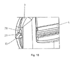
FIG. 18: is a detailed view of a fifth embodiment of the belt tongue.
DETAILED DESCRIPTION
The first exemplary embodiment of a belt tongue 1 depicted in FIGS. 1 to 4 serves for explaining the functionality of the belt tongue 1, but does not have all claimed features. The belt tongue 1 comprises a tongue body 3 that extends in an insertion direction 2. A cavity 5 is formed in the tongue body 3, which is bounded below in sections, in the insertion direction 2 by a clamping edge 8. Laterally to the clamping edge 8, recesses 10 extend in the insertion direction 2. On the side of the cavity 5 facing away from the clamping edge 8, projections 14 on the tongue body 3 are formed and protrude into the cavity 5. Furthermore, on the tongue body 3 a retaining point 17 is formed and a middle region of a leaf spring 12 comes to rest thereon.
The belt tongue 1 further includes a clamping element 4 that is pivotably supported in the tongue body 3 by bearing pins 18. A cam 11 tapering in one direction is formed adjacent to each bearing pin 18. In the assembled state the ends of the leaf spring 12 rest on the cam 11 such that a torque is introduced into the clamping element 4.
The clamping element 4 further includes grooves 15 with end surfaces 16 in which the projections 14 are disposed in the assembled state of the belt tongue 1.
The clamping element 4 further includes guide sections 9 in the lateral region which in the assembled state are at least partially disposed in the recess 10 of the cavity 5. As can be seen in particular in FIG. 3, a gap is formed between a clamping region 22 of the clamping element 4 and the clamping edge 8 of the cavity 5, through which a belt strap 7 is guidable. This gap 6 is delimited on both sides by the guide sections 9 of the clamping element 4, so that the belt strap 7 is disposed between the guide sections 9. The belt strap 7 thus cannot arrive between the clamping element 4 and a lateral edge 19 of the cavity 5.
As can be seen from FIG. 5, in a pass-through position the gap 6 formed between the clamping region 22 of the clamping element 4 and the clamping edge 8 of the cavity 5 is sufficiently large that the belt strap 7 is freely movable. The belt strap 7 here is laterally delimited by the guide sections 9.
If a force is now introduced into a lap-belt section of the belt strap 7, then the clamping element 4 is pivoted by this force so that the gap 6 diminishes is size until finally the belt strap 7 is clamped between the clamping region 22 of the clamping element 4 and the clamping edge 8, and thus a stressed position is reached as is depicted in FIG. 6. Moreover in this stressed position, the end surface 16 of the groove 15 comes into abutment with the projections 14, whereby the force acting on the belt strap 7 is limited.
In FIG. 7, a second embodiment of a belt tongue having all features essential to the invention is depicted, which differs from the first embodiment primarily through the provision of a pivotable support of the clamping element 4 and the applying of a restoring force, wherein in addition the function of the clamping element 4 and the guide section 9 attached thereto is identical to the first embodiment, so that hereinafter only the differences are discussed.
According to the second embodiment, the clamping element 4 is pivotably supported by an elastically deformable torsion bar 13 on the tongue body 3, wherein in the stressed position, the torsion bar 13 simultaneously exerts a restoring force on the clamping element 4. For this purpose the torsion bar 13 is attached on a first side 20 of the tongue body 3 for conjoint rotation therewith, i.e. they are fixed for non-rotatable relative motion), by means of a friction fit into a first socket 28 a on the tongue body 3. Such connection is provided by the profiled head 35 of the torsion bar 13 which form fits into socket 28 a. On the side 21 of the tongue body 3 opposite the first side 20, the torsion bar 13 which is guided through the entire clamping element 4 is rotatably supported in a socket 28 b in the tongue body 3, as can be seen from FIG. 11. The end of the torsion bar 13 is permitted to rotate within socket 28 b.
In order that the torsion bar 13 depicted in FIG. 8 can be deformed (twisted) over a longest possible length during a twisting (rotational) movement of the clamping element 4, the torsion bar 13 is only connected to the clamping element 4 for conjoint rotation therewith (i.e. rotatably fixed) on a side of the clamping element 4 associated with the second side 21 of the tongue body 3 by form fits provided by the mating cross-sectional configurations of the torsion bar 13 and an internal socket 36 at an end of the clamping element 4, as is depicted in FIGS. 10 and 14. The clamping element 4 further has an internal passageway (not shown) for torsion bar 13 which allows the torsion bar to twist between the ends of the clamping element 4. In this respect it can be seen in FIG. 9 that the torsion bar 13 is disposed on the side of the clamping element 4 associated with the first side 20 of the tongue body 3 rotatable with respect to the clamping element 4 in the socket 28.
If the clamping element 4 is now pivoted out of its pass-through position into its stressed position, the torsion bar 13 is twisted over almost its entire length between the attachment for conjoint rotation to the first side 20 of the clamping element 4 at socket 28 a and the connection for conjoint rotation of the torsion bar 13 to the clamping element 4 at socket 36, wherein due to the resultant elastic deformation of the torsion bar 13, a restoring force is exerted on the clamping element 4.
In FIG. 12, a third embodiment of a belt tongue 1 having all essential features of the invention is depicted, wherein the functional principle of the belt tongue 1 essentially corresponds to the functional principle of the previously described belt tongues. Similar to the second embodiment, the belt tongue 1 includes a torsion bar 13, which exerts a restoring force on the clamping element 4 directed in the pass-through position during pivoting of the clamping element 4. In the following therefore mainly the differences to the above-described embodiments are discussed.
The clamping element 4 features guide elements 23 laterally outward on its guide sections 9. On lateral inner sides directed toward the cavity 5, the tongue body 3 features guide depressions 24 corresponding to the guide elements 23, and an assembly depression 25 adjoins each of these guide depressions. As can be seen in particular from the sectional view depicted in FIG. 13, which shows a section through the belt tongue 1 in the region of the guide element 23 and the guide cavity 24, the guide cavity 24 is configured in approximately a half-ring shape, to which the rectilinear assembly depression 25 connects. Due to the assembly depressions 25, the clamping element 4 can be brought into its assembly position with its quarter-ring-shaped guide elements 23. For the assembly, the clamping element 4 is linearly displaced on both sides with the guide elements 23 through the assembly depressions 25, wherein the clamping element 4 is prevented from slipping back against the now greater extension of the guide elements 23, as projected onto the width of the assembly depressions 25. Due to the guide elements 23 and the guide depressions 24, a pivoting support of the clamping element 4 in the tongue body 3 is thus achieved. In this context, the torsion bar 13 disposed in the sockets 28 in the clamping element 4 not only has the function of exerting a restoring force on the pivoted clamping element 4, but also the function of securing the clamping element 4 against slipping back through the assembly depressions 25 into a correspondingly pivoted position.
As can also be seen from FIGS. 13 and 14, the tongue body 3 is formed of a metallic core 26 with molded-over plastic 27. In FIG. 14, a sectional view is shown through the tongue body 3 in the region of the guide section 9. As can be seen in a synopsis with FIG. 12, the guide section 9 is disposed in a recess 10 formed in the plastic 27, wherein the clamping element slides into abutment on the plastic 27 in the upper region of the cavity 5 during the pivoting movement.
In FIG. 15 a torsion bar 13 is shown for a fourth embodiment of a belt tongue 1 having all features essential to the invention. The torsion bar 13 includes a first end 29 and a second end 30. In the assembled state the torsion bar 13 is fixed so that it does not turn by the first end 29 in a socket 28 of a tongue body 3. The second end 30 is secured from twisting with respect to a clamping element 4, but it can be twisted with respect to a further socket in the tongue body 3. In the region of the first end 29 the torsion bar 13 has a first cross-sectional contour 31 and in the region of the second end 30, a second cross-sectional contour 32. The cross-sectional contours 31, 32 are identical in their shape, wherein, however, they are rotationally offset to each other with respect to a longitudinal axis of the torsion bar 13. The torsion bar 13 continuously transitions from the first end 29 to the second end 30 while maintaining the cross-sectional shape, wherein the orientation of the cross-sectional shape changes.
In FIG. 16 the belt tongue 1 is depicted with installed clamping element 4 and installed torsion bar 13. The tongue body 3 of the belt tongue 1 includes sockets 28 on its lateral walls, whose socket cross-sections 33 are respectively depicted on the bottom of FIG. 16. On the left side the socket 28 includes a socket cross-section 33 that corresponds in shape to the cross-sectional shape of the torsion bar 13. On the left side the socket 28 has a circular socket cross-section, so that the torsion bar 13 can rotate in this socket 28 by its second end 30. The clamping element 4 includes a channel for receiving the torsion bar 13 whose channel cross section 34 is indicated in the bottom of FIG. 16. On the left side the cross-section of the channel has a circular shape, while on the right side the cross-section of the channel has a rectangular shape corresponding to the cross-sectional shape of the torsion bar 13.
In the assembly of the torsion bar 13 indicated from top to bottom in FIG. 17(a), the torsion bar 13 is initially introduced into the channel of the clamping element 4 through the socket 28. The clamping element here can initially be in any orientation since the torsion bar is rotatable relative to the clamping element on the left side depicted in the Figure, due to the circular channel cross-section 34. In order to push the torsion bar 4 farther into the clamping element 4 as shown in FIG. 17(b), the clamping element 4 should be located in its pass-through position so that the second end of the torsion bar 13 can engage in the cross-sectional contour of the channel adapted to the second end 30. In order that now the first end 29 of the torsion bar 13 can be introduced in the socket 28 in the tongue body, the torsion bar 13 having a twisted shape must be twisted by its first end 29 with respect to the second end 30 fixed against a relative rotation in the clamping element 4, whereby a torsional moment is generated in the torsion bar 30, which position is shown in FIG. 17(c). The restoring force resulting therefrom is directed in the pass-through position of the clamping element 4.
In yet another embodiment according to FIG. 18 including all features essential to the invention, the torsion bar 13 is angled in the region of its first end 29. The torsion bar 13 already fixed to the clamping element 4 for conjoint rotation therewith by its second end 30, must be twisted by the first end 29 relative to the second end 30 so that the angled end 29 can engage in the correspondingly formed socket 28 in the belt body 3. Also with this embodiment, a pre-stress is generated in advance in the pass-through position.
While the above description constitutes the preferred embodiment of the present invention, it will be appreciated that the invention is susceptible to modification, variation and change without departing from the proper scope and fair meaning of the accompanying claims.

Claims (12)

The invention claimed is:
1. A belt tongue for a motor vehicle seatbelt restraint system having a belt strap, comprising a tongue body extending in an insertion direction, wherein a clamping element is disposed such that the belt strap guided through a cavity in the tongue body and extending through a gap formed between the clamping element and the tongue body is movable in an unstressed pass-through position, and in a stressed position caused by a tensile force introduced in the belt strap, is clamped to a clamp edge of the cavity by the clamping element which is pivot-mounted in the tongue body and pivotable into the cavity, wherein in the stressed position, wherein a torsion bar exerts a restoring force on the clamping element directed toward the pass-through position of the clamping element, the torsion bar being a bar extending from a first end to a second end, wherein the first end of the torsion bar is secured in a first socket of the tongue body in a non-rotating manner and the second end of the torsion bar is placed in a second socket of the tongue body in a rotating manner, and wherein the clamping element is disposed between the first socket and the second socket of the tongue body and includes a channel having a first side and a second side, and a cross-section of the first side guides the torsion bar in a rotating manner and a cross-section of the second side corresponds to a cross-sectional shape of the torsion bar for securing the torsion bar to the clamping element in a non-rotating manner such that a pivoting movement between the tongue body and the clamping element causes torsional deflection of the torsion bar.
2. A belt tongue according to claim 1, wherein the torsion bar is only fixed at the first end on the first socket of the tongue body and is connected to the clamping element at the second end on the second side of the clamping element which is not associated with the first socket of the tongue body associated with the torsion bar.
3. A belt tongue according to claim 1 further comprising guide sections disposed laterally on the clamping element, between which the belt strap extends so that in a lateral region of the cavity the belt strap does not arrive between the clamping element and the tongue body.
4. The belt tongue according to claim 1, wherein guide elements project laterally from the clamping element, which guide elements are at least partially surrounding guide depressions in the tongue body, wherein the guide elements and the guide depressions are formed such that the pivoting movement of the clamping element is guided by the guide elements.
5. The belt tongue according to claim 4, wherein a rectilinear assembly depression extending up to an edge of the tongue body connects to each of the guide depressions, by which the clamping element is linearly displaced during assembly with the guide elements, wherein the clamping element is secured against sliding-back by a subsequent pivoting.
6. The belt tongue according to claim 1, wherein the belt strap is pulled transverse to the insertion direction through the cavity in the tongue body.
7. The belt tongue according to claim 1, wherein the torsion bar in the unstressed pass-through position exerts a torsional force onto the clamping element directed opposite the stressed position while the clamping element is in the unstressed pass-through position.
8. The belt tongue according to claim 7, wherein the torsion bar is designed such that the first end of the torsion bar fixed in the first socket for securing to the tongue body, must be twisted with respect to the second end fixed to the clamping element, while the clamping element is located in the unstressed pass-through position.
9. The belt tongue according to claim 8, further comprising a first cross-sectional contour that corresponds in the cross-sectional shape to a second cross-sectional contour of the second end, wherein in the unstressed state of the torsion bar, the first and second cross-sectional contours are rotationally offset with respect to each other about an axis of rotation and a transition from the first cross-sectional contour to the second cross-sectional contour is continuous, while maintaining the cross-sectional shape, so that with the second end of torsion bar fixedly inserted in the clamping element for conjoint rotation, the torsion bar is torsionally deformed about the axis of rotation by insertion of the first end into the first socket of the tongue body.
10. The belt tongue according to claim 1, wherein the cross-section of the first side of the channel is configured for allowing the clamping element to be initially in a non-pass-through position when the torsion bar is pushed into the clamping element through the first socket on the outside of the tongue body.
11. A belt tongue for a motor vehicle seatbelt restraint system having a belt strap, comprising a tongue body extending in an insertion direction, wherein a clamping element is disposed such that the belt strap guided through a cavity in the tongue body and extending through a gap formed between the clamping element and the tongue body is movable in an unstressed pass-through position, and in a stressed position caused by a tensile force introduced in the belt strap, is clamped to a clamp edge of the cavity by the clamping element which is pivot-mounted in the tongue body and pivotable into the cavity, wherein in the stressed position a torsion bar exerts a restoring force on the clamping element directed toward the pass-through position of the clamping element, the torsion bar in the form of a unitary structure having a first end and a second end, and a first cross-sectional contour on the first end of the torsion bar corresponds in a cross-sectional shape to a second cross-sectional contour on the second end of the torsion bar, wherein in the stressed state of the torsion bar, the first and second cross-sectional contours of the torsion bar are rotationally offset with respect to each other about its longitudinal axis such that the torsion bar is torsionally deformed about the axis of rotation by insertion of the first end into a first socket of the tongue body with the second end secured to the clamping element for conjoint rotation, whereby a torsional force is applied onto the clamping element in the pass-through position.
12. A belt tongue for a motor vehicle seatbelt restraint system having a belt strap, comprising a tongue body extending in an insertion direction, wherein a clamping element is disposed such that the belt strap guided through a cavity in the tongue body and extending through a gap formed between the clamping element and the tongue body is movable in an unstressed pass-through position, and in a stressed position caused by a tensile force introduced in the belt strap, is clamped to a clamp edge of the cavity by the clamping element which is pivot-mounted in the tongue body and pivotable into the cavity, wherein in the stressed position a torsion bar exerts a restoring force on the clamping element directed toward the pass-through position of the clamping element, the torsion bar in the form of a unitary structure having a first end and a second end, and the torsion bar has a cross-sectional shape according to a longitudinal axis of the torsion bar, and wherein a first cross-sectional contour of the first end and a second cross-sectional contour of the second end are rotationally offset to each other with respect to the longitudinal axis of the torsion bar while maintaining the identical cross-sectional shape of the torsion bar.
US15/513,587 2014-09-30 2015-09-30 Belt tongue comprising a torsion bar Active US10442394B2 (en)

Applications Claiming Priority (4)

Application Number Priority Date Filing Date Title
DE102014114207.1A DE102014114207B4 (en) 2014-09-30 2014-09-30 Lock tongue with a guide portion having a clamping element
DE102014114207 2014-09-30
DE102014114207.1 2014-09-30
PCT/EP2015/072514 WO2016050820A1 (en) 2014-09-30 2015-09-30 Belt tongue comprising a torsion bar

Publications (2)

Publication Number Publication Date
US20170297528A1 US20170297528A1 (en) 2017-10-19
US10442394B2 true US10442394B2 (en) 2019-10-15

Family

ID=54199250

Family Applications (1)

Application Number Title Priority Date Filing Date
US15/513,587 Active US10442394B2 (en) 2014-09-30 2015-09-30 Belt tongue comprising a torsion bar

Country Status (6)

Country Link
US (1) US10442394B2 (en)
EP (1) EP3201050B1 (en)
CN (1) CN107107862B (en)
DE (1) DE102014114207B4 (en)
ES (1) ES2690478T3 (en)
WO (2) WO2016050763A1 (en)

Cited By (3)

* Cited by examiner, † Cited by third party
Publication number Priority date Publication date Assignee Title
US20180220749A1 (en) * 2017-02-08 2018-08-09 Kabushiki Kaisha Tokai-Rika-Denki-Seisakusho Tongue for seatbelt device
US11311431B2 (en) * 2019-02-21 2022-04-26 Stryker Corporation Adjuster for use with flexible restraints
US20220132998A1 (en) * 2019-04-12 2022-05-05 Zf Automotive Germany Gmbh Tongue for a seat belt

Families Citing this family (12)

* Cited by examiner, † Cited by third party
Publication number Priority date Publication date Assignee Title
DE102014017788B4 (en) * 2014-12-03 2020-03-26 Trw Automotive Gmbh Tongue
DE102016106440B4 (en) * 2016-04-08 2019-05-09 Autoliv Development Ab Locking tongue with deflection element
JP2018184134A (en) * 2017-04-27 2018-11-22 Joyson Safety Systems Japan株式会社 Tongue and seat belt device
DE102017121613A1 (en) * 2017-09-18 2019-03-21 Autoliv Development Ab Lock tongue with cover
US10512309B2 (en) * 2018-01-11 2019-12-24 Ford Global Technologies, Llc Seat belt connector tongue assembly having locking mechanism
US10543806B2 (en) * 2018-02-27 2020-01-28 Ford Global Technologies, Llc Seatbelt assembly
US10434976B2 (en) * 2018-02-27 2019-10-08 Ford Global Technologies, Llc Seatbelt assembly
CN108209061B (en) * 2018-03-29 2024-01-19 浙江松原汽车安全系统股份有限公司 Locking type lock tongue
JP7063235B2 (en) * 2018-10-30 2022-05-09 トヨタ自動車株式会社 Seat belt device
US11254282B2 (en) 2019-01-07 2022-02-22 Joyson Safety Systems Acquisition Llc Cinch locking tongue for a vehicle occupant restraint system
CN110450753B (en) * 2019-09-18 2025-02-11 延锋汽车智能安全系统有限责任公司 Seat belt self-locking tongue
CN116605171B (en) * 2023-03-29 2025-10-10 奇瑞汽车股份有限公司 Seat belt tongue structure

Citations (21)

* Cited by examiner, † Cited by third party
Publication number Priority date Publication date Assignee Title
US2919481A (en) * 1955-11-14 1960-01-05 Gentex Corp Adjustable buckle
US3414947A (en) * 1967-07-03 1968-12-10 Holmberg Gote Eskil Yngve Strap fasteners
DE2320314A1 (en) 1973-04-21 1974-10-31 Klippan Gmbh ADJUSTABLE FITTING FOR SAFETY BELT
US4184234A (en) * 1978-09-18 1980-01-22 Indiana Mills & Manufacturing Inc. Anti-creep seat belt buckle and tongue combination
US4876770A (en) * 1988-10-03 1989-10-31 Indiana Mills & Manufacturing, Inc. Anti-creep cam bar
US5311653A (en) * 1993-03-11 1994-05-17 Indiana Mills & Manufacturing, Inc. Web adjuster for plastic coated web
US5411292A (en) * 1994-04-15 1995-05-02 Allied-Signal Inc. Seat belt system with locking guide loop assembly
US5870816A (en) * 1997-05-19 1999-02-16 Trw Vehicle Safety Systems Inc. Method of assembling a tongue assembly for use with a seat belt system
US7010836B2 (en) * 2003-02-17 2006-03-14 Indiana Mills & Manufacturing, Inc. Web adjuster device
US20060138852A1 (en) * 2004-12-27 2006-06-29 Takata Corporation Tongue and seat belt apparatus employing the same
US20060226694A1 (en) * 2005-04-07 2006-10-12 Takata Corporation Seatbelt apparatus
WO2007090551A1 (en) 2006-02-09 2007-08-16 Autoliv Development Ab Belt latch for a safety belt
US8087696B2 (en) * 2007-06-11 2012-01-03 Lap Belt Cinch, Inc. Vehicle occupant restraint and method
DE202010013986U1 (en) 2010-09-20 2012-01-10 Trw Vehicle Safety Systems Inc. Locking tongue for a safety belt
US20120286501A1 (en) 2011-05-09 2012-11-15 Tk Holdings Inc. Occupant restraint system
US20130341994A1 (en) * 2012-06-21 2013-12-26 Tk Holdings Inc. Seat belt system with rollover locking tongue
WO2014013987A1 (en) 2012-07-18 2014-01-23 タカタ株式会社 Tongue and seatbelt device using same
US8813316B2 (en) * 2011-10-25 2014-08-26 GM Global Technology Operations LLC Seat belt latch plate assembly
WO2015140341A1 (en) 2014-03-19 2015-09-24 Autoliv Development Ab Buckle tongue
US9174554B2 (en) * 2012-05-09 2015-11-03 Britax Childcare Pty Ltd. Seat belt lock-off for a safety seat
WO2015172879A1 (en) 2014-05-16 2015-11-19 Trw Automotive Gmbh Latch plate and method for producing a latch plate

Family Cites Families (2)

* Cited by examiner, † Cited by third party
Publication number Priority date Publication date Assignee Title
DE102012020919B4 (en) * 2012-10-25 2018-02-15 Autoliv Development Ab Buckle tongue device for a safety belt
DE102013003109A1 (en) * 2013-02-25 2014-08-28 Trw Automotive Gmbh tongue

Patent Citations (27)

* Cited by examiner, † Cited by third party
Publication number Priority date Publication date Assignee Title
US2919481A (en) * 1955-11-14 1960-01-05 Gentex Corp Adjustable buckle
US3414947A (en) * 1967-07-03 1968-12-10 Holmberg Gote Eskil Yngve Strap fasteners
DE2320314A1 (en) 1973-04-21 1974-10-31 Klippan Gmbh ADJUSTABLE FITTING FOR SAFETY BELT
US3898715A (en) 1973-04-21 1975-08-12 Klippan Gmbh Fitting for adjusting a safety belt
US4184234A (en) * 1978-09-18 1980-01-22 Indiana Mills & Manufacturing Inc. Anti-creep seat belt buckle and tongue combination
US4876770A (en) * 1988-10-03 1989-10-31 Indiana Mills & Manufacturing, Inc. Anti-creep cam bar
US5311653A (en) * 1993-03-11 1994-05-17 Indiana Mills & Manufacturing, Inc. Web adjuster for plastic coated web
US5411292A (en) * 1994-04-15 1995-05-02 Allied-Signal Inc. Seat belt system with locking guide loop assembly
US5870816A (en) * 1997-05-19 1999-02-16 Trw Vehicle Safety Systems Inc. Method of assembling a tongue assembly for use with a seat belt system
US7010836B2 (en) * 2003-02-17 2006-03-14 Indiana Mills & Manufacturing, Inc. Web adjuster device
US20060138852A1 (en) * 2004-12-27 2006-06-29 Takata Corporation Tongue and seat belt apparatus employing the same
US20060226694A1 (en) * 2005-04-07 2006-10-12 Takata Corporation Seatbelt apparatus
WO2007090551A1 (en) 2006-02-09 2007-08-16 Autoliv Development Ab Belt latch for a safety belt
US20090025193A1 (en) 2006-02-09 2009-01-29 Fredrik Fyhr Belt Latch for a Safety Belt
US8087696B2 (en) * 2007-06-11 2012-01-03 Lap Belt Cinch, Inc. Vehicle occupant restraint and method
DE202010013986U1 (en) 2010-09-20 2012-01-10 Trw Vehicle Safety Systems Inc. Locking tongue for a safety belt
US20120068520A1 (en) 2010-09-20 2012-03-22 Trw Vehicle Safety Systems Inc. Locking tongue for a safety belt
US20120286501A1 (en) 2011-05-09 2012-11-15 Tk Holdings Inc. Occupant restraint system
DE112012002030T5 (en) 2011-05-09 2014-02-13 Tk Holdings Inc. Occupant restraint system
US8813316B2 (en) * 2011-10-25 2014-08-26 GM Global Technology Operations LLC Seat belt latch plate assembly
US9174554B2 (en) * 2012-05-09 2015-11-03 Britax Childcare Pty Ltd. Seat belt lock-off for a safety seat
US20130341994A1 (en) * 2012-06-21 2013-12-26 Tk Holdings Inc. Seat belt system with rollover locking tongue
WO2014013987A1 (en) 2012-07-18 2014-01-23 タカタ株式会社 Tongue and seatbelt device using same
US20150173461A1 (en) 2012-07-18 2015-06-25 Takata Corporation Tongue and seat belt device using same
WO2015140341A1 (en) 2014-03-19 2015-09-24 Autoliv Development Ab Buckle tongue
WO2015172879A1 (en) 2014-05-16 2015-11-19 Trw Automotive Gmbh Latch plate and method for producing a latch plate
US20170055643A1 (en) 2014-05-16 2017-03-02 Trw Automotive Gmbh Latch plate and method for producing a latch plate

Non-Patent Citations (2)

* Cited by examiner, † Cited by third party
Title
German Office Action, Application No. 10 2014 114 207.1, dated Sep. 14, 2015, 2 pgs.
International Search Report for Application No. PCT/EP2015/072514, dated Dec. 15, 2016, Form PCT/ISA/210, 3 pgs.

Cited By (4)

* Cited by examiner, † Cited by third party
Publication number Priority date Publication date Assignee Title
US20180220749A1 (en) * 2017-02-08 2018-08-09 Kabushiki Kaisha Tokai-Rika-Denki-Seisakusho Tongue for seatbelt device
US11311431B2 (en) * 2019-02-21 2022-04-26 Stryker Corporation Adjuster for use with flexible restraints
US20220132998A1 (en) * 2019-04-12 2022-05-05 Zf Automotive Germany Gmbh Tongue for a seat belt
US11930893B2 (en) * 2019-04-12 2024-03-19 Zf Automotive Germany Gmbh Tongue for a seat belt

Also Published As

Publication number Publication date
CN107107862B (en) 2019-11-08
DE102014114207A1 (en) 2016-03-31
ES2690478T3 (en) 2018-11-21
EP3201050A1 (en) 2017-08-09
WO2016050763A1 (en) 2016-04-07
CN107107862A (en) 2017-08-29
WO2016050820A1 (en) 2016-04-07
DE102014114207B4 (en) 2016-11-17
EP3201050B1 (en) 2018-07-18
US20170297528A1 (en) 2017-10-19

Similar Documents

Publication Publication Date Title
US10442394B2 (en) Belt tongue comprising a torsion bar
EP2430941B1 (en) Locking tongue for a safety belt
US9340128B2 (en) Vehicle seat
EP1676760B1 (en) Tongue and seat belt apparatus employing the same
US8820790B2 (en) Vehicle seat
US8840178B2 (en) Seatback for vehicle seat
US8950782B2 (en) Mounting device for securing a seat belt buckle
US20020050707A1 (en) Buckle device
US20060186720A1 (en) Translation movement guidance mechanism with positional locking, for adjustable elements of an automobile vehicle seat
JP4110037B2 (en) Through anchor
US20150258925A1 (en) Device for assembling rear seat back assembly
US10377286B2 (en) Folding head restraint mechanism
EP2700773B1 (en) Handle base attachment structure
KR20160124771A (en) Locking device
US10434912B2 (en) Armrest brake
US20110127760A1 (en) Belt Buckle
CA3051398A1 (en) Cam buckle
CN112572251B (en) Seat belt anchorage
JP5204628B2 (en) Assist grip
KR101564231B1 (en) Locking tongue of seat belt
KR101449153B1 (en) Convertible webbing guide of rear seat back for vehicle
US8813323B2 (en) Shockproof quick-release fastener for an end fitting of a safety belt
CN102958761B (en) For the quick acting closure being fixed on the end of automobile of automobile safety seat belt
EP2006196A1 (en) Safety release for fender
JP2008530400A (en) Device for locking and unlocking the backrest of a seat, in particular an automobile seat, in particular

Legal Events

Date Code Title Description
AS Assignment

Owner name: AUTOLIV DEVELOPMENT AB, SWEDEN

Free format text: ASSIGNMENT OF ASSIGNORS INTEREST;ASSIGNORS:HERMANN, MICHEL;GRIKSCHAT, MARTIN;KRAMBECK, INGA;AND OTHERS;SIGNING DATES FROM 20170315 TO 20170319;REEL/FRAME:041696/0080

STPP Information on status: patent application and granting procedure in general

Free format text: RESPONSE TO NON-FINAL OFFICE ACTION ENTERED AND FORWARDED TO EXAMINER

STPP Information on status: patent application and granting procedure in general

Free format text: FINAL REJECTION MAILED

STPP Information on status: patent application and granting procedure in general

Free format text: RESPONSE AFTER FINAL ACTION FORWARDED TO EXAMINER

STPP Information on status: patent application and granting procedure in general

Free format text: NOTICE OF ALLOWANCE MAILED -- APPLICATION RECEIVED IN OFFICE OF PUBLICATIONS

STPP Information on status: patent application and granting procedure in general

Free format text: PUBLICATIONS -- ISSUE FEE PAYMENT VERIFIED

STPP Information on status: patent application and granting procedure in general

Free format text: AWAITING TC RESP, ISSUE FEE PAYMENT VERIFIED

STPP Information on status: patent application and granting procedure in general

Free format text: PUBLICATIONS -- ISSUE FEE PAYMENT VERIFIED

STCF Information on status: patent grant

Free format text: PATENTED CASE

MAFP Maintenance fee payment

Free format text: PAYMENT OF MAINTENANCE FEE, 4TH YEAR, LARGE ENTITY (ORIGINAL EVENT CODE: M1551); ENTITY STATUS OF PATENT OWNER: LARGE ENTITY

Year of fee payment: 4